

Page 1

INSTALLATION MANUAL
Document : ESS-01-ED05K000E00-EN-161114
Status : 11/2016
Energy Storage
System
Please read this manual carefully before installing your
set and retain it for future reference.
MODEL
ED05K000E00
*MFL69509601*
www.lg.com/global/business/ess
Page 2

Getting Started2
Safety Information
IMPORTANT : THIS PRODUCT SHOULD NOT BE USED FOR ANY PURPOSE OTHER THAN THE PURPOSE
DESCRIBED IN THIS INSTALLATION MANUAL.
1
Getting Started
WARNING
yThere is high possibility of electric shock or serious burns due to the high voltages in power conditioning
circuits.
yHigh voltages on AC and DC cables. Risk of death or serious injury due to electric shock.
yA potentially hazardous circumstance such as excessive heat or electrolyte mist may occur due to
improper operating conditions, damage, misuse and/or abuse.
yThis product have potential danger such as death or serious injury by re, high voltages or explosion if
appropriate precautions are not read or fully understood.
yDo not place ammable or potentially explosive objects near the product.
yDo not place any kind of objects on top of the product during operation.
y All work on the PV modules, power conditioning system, and battery system must be carried out by
qualied personnel only.
yElectrical installations must be done in accordance with the local and national electrical safety standards.
yWear rubber gloves and protective clothing (protective glasses and boots) when working on high voltage/
high current systems such as PCS and battery systems.
Indicates a potentially dangerous situation. Death or serious injury may result
if appropriate precautions are not taken.
yThere is a risk of electric shock. Do not remove cover. There is no user serviceable parts inside. Refer
servicing to qualied and accredited service technician.
yElectrical shock hazard. Do not touch uninsulated wires when the product cover is removed.
yIn the event of fault, the system must not be restarted. Product maintenance of repairs must be
performed by qualied personnel, or personnel from an authorized support center.
CAUTION
yThis product is intended for residential use only and should not be used for commercial or industrial.
yBefore testing electrical parts inside the system, it takes at least 10-minute standby period of time to
complete discharging the system.
yThe contents included in this box are power conditioning system and its accessories, and the entire weight
amounts to over 34 kg. Serious injury may occur due to the heavy weight of the product. Therefore,
special care must be taken in handling. Make sure to have at least two persons deliver and remove the
package.
yDo not use the damaged, cracked or frayed electrical cables and connectors. Protect the electrical cables
from physical or mechanical abuse, such as being twisted, kinked, pinched, closed in a door or walked
upon. Periodically examine the electrical cables of your product, and if its appearance indicates damage
or deterioration, discontinue use of this product, and have the cables replaced with an exact replacement
part by a qualied personnel.
Indicates a situation where damage or injury could occur. If it is not avoided,
minor injury and/or damage to property may result.
Page 3

Getting Started 3
NOTE
CAUTION
yEnsure that you connect the earth ground wire to prevent possible electric shock. Do not try to ground
the product by connecting it to telephone wires, lightning rods or gas pipes.
yThe product should not be exposed to water (dripping or splashing) and no objects lled with liquids, such
as vases, should be placed on the product.
yTo prevent re or electric shock hazard, do not expose this production to rain or moisture.
yDo not block any ventilation openings. Ensure reliable operation of the product and protect it from over
heating. The openings shall never be blocked by placing any object on this product.
yThe temperature of metal enclosure may be high during operation.
yIn order to avoid radio-interference, all accessories (like a smart meter) intended for connection to
the product shall be suitable for use in residential, commercial and light-industry areas. Usually this
requirement is fullled if the equipment complies with the class B limits of EN55022.
yThe product must be disposed of according to local regulations.
yThe electrical installation of this unit must only be performed by electricians or technicians, qualied to
install PCS.
yDanger of damaging the PCS by overload. Only connect the proper wire to DC terminal block. Refer to the
installation wiring diagram for details.
Indicates a situation where damage or injury could occur. If it is not avoided,
minor injury and/or damage to property may result.
1
Getting Started
yConnect the DC+ and DC- cables to the correct DC+ and DC- terminals on the product.
yDo not step on the product or the product package. The product may be damaged.
yDo not dispose of batteries in a re. The batteries may explode.
yDo not open or damage batteries. Released electrolyte is harmful to the skin and eyes. It may be toxic.
yA battery can present a risk of electrical shock and high short-circuit current. The following precautions
should be observed when working on batteries.
a) Remove watches, ring, or other metal objects.
b) Use tools with insulated handles.
c) Wear rubber gloves and boots.
d) Do not lay tools or metal parts on top of battery.
Indicates a risk of possible damage to the product.
yBefore making connections, please make sure the PV array open circuit voltage is within 800 V. Otherwise
the product could be damaged.
yNever use any solvents, abrasives or corrosive materials to clean this product.
yDo not store on or place against any objects to the product. It may cause serious defects or malfunction.
yBefore making a connection, make sure the PV switch on this product is switched off.
yThis unit is designed to feed power to the public power grid only. Do not connect this unit to an AC
source or generator. Connecting the product to external devices could result in serious damage to your
equipment.
yServing of batteries should be performed or supervised by personnel knowledgeable about batteries and
the required precautions.
Page 4

4 Table of Contents
Table of Contents
Getting Started
Safety Information ...................................................................2
Product Features .....................................................................6
Unpacking ...........................................................................9
Contents of this product ..........................................................................9
Additional components for installation .............................................................9
Name of each part ...................................................................10
Front and Rear ...................................................................................10
LED indications ..................................................................................10
Lower parts .....................................................................................11
Inner parts (lower cover opened) .................................................................11
Installation
Choice of location ...................................................................12
Mounting Location ...............................................................................12
Minimum clearance ..............................................................................13
Wall Mounting ......................................................................14
Connections ........................................................................17
Connection Overview ............................................................................17
PV array connections .............................................................................18
Battery connections .............................................................................20
Power grid connections ..........................................................................23
Smart meter and internet connection .............................................................26
Settings
Installer settings ....................................................................29
Basic operation ..................................................................................29
[Network] settings ..............................................................................30
[PV/Meter] settings. . . . . . . . . . . . . . . . . . . . . . . . . . . . . . . . . . . . . . . . . . . . . . . . . . . . . . . . . . . . . . . . . . . . . . . . . . . . . .31
[PCS/Battery] settings ...........................................................................32
[Operating Test] settings .........................................................................33
[Firmware/Reset] settings .......................................................................34
[Change Password] settings ......................................................................35
System Log ......................................................................................35
EnerVu settings .....................................................................36
Creating a new account (Owner) .................................................................36
Creating a new account (Installer) ................................................................38
Registering the PCS (Installer) ....................................................................39
Page 5

Table of Contents
Troubleshooting
Error Codes and Messages ...........................................................40
PCS error codes ..................................................................................40
Battery error codes ..............................................................................42
5
Appendix
Maintenance ........................................................................45
Cleaning the product .............................................................................45
Inspecting regularly ..............................................................................45
Disposing the product ............................................................................45
Disassemble the product .........................................................................45
Checking the PCS setting information ............................................................47
Specifications .......................................................................48
1
2
3
4
5
Page 6
1
Getting Started6
Product Features
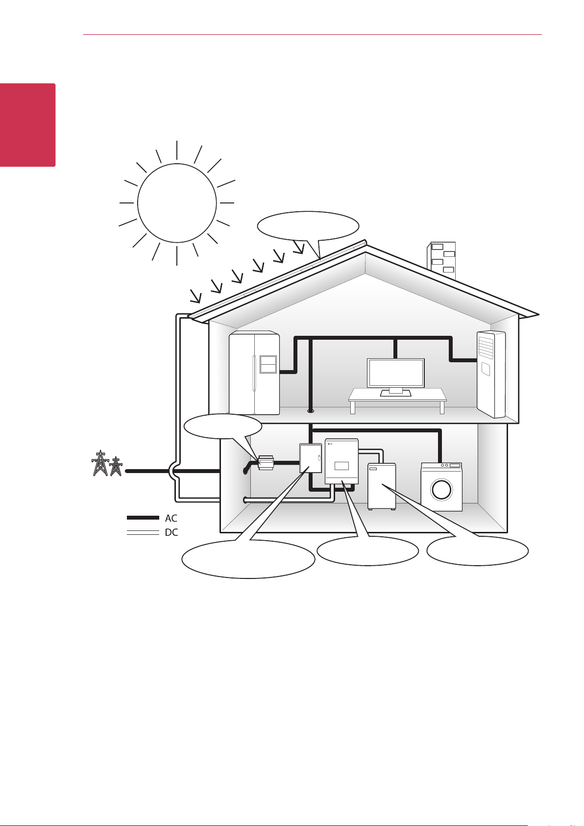
This product is intended to store direct current (DC) electricity generated from photovoltaic (PV) to the
connected Lithium-Ion Battery, and convert direct current (DC) electricity from the connected battery to
alternating current (AC) electricity and feed this into the power grid.
Getting Started
PV array
Smart Meter
Power Grid
AC Grid
Distribution Box
PCS
Battery
(AC circuit breaker)
The electricity generated from a PV array can be stored to the connected battery or sold to energy supply
companies.
yDC-Coupled ESS
LG ESS can achieve higher system efciency due to simpler power conversion process.
yThree-Phase Connection
3-phase connection secures phase balancing.
ySmart Management
With built-in Smart PMS, it analyses PV generation and load consumption and implements to charge and
discharge immediately. Also it monitors main system & battery conditions to maintain its stable condition
always.
yWeb-monitoring Service
Customers and installers can monitor their ESS with various devices such as PC, tablet or smart phones.
yEasy System Setup
With 7” touch-screen, installer does not need a PC for system installation. Touch screen UI allows installer to
set-up, pre-test and monitor system.
Page 7
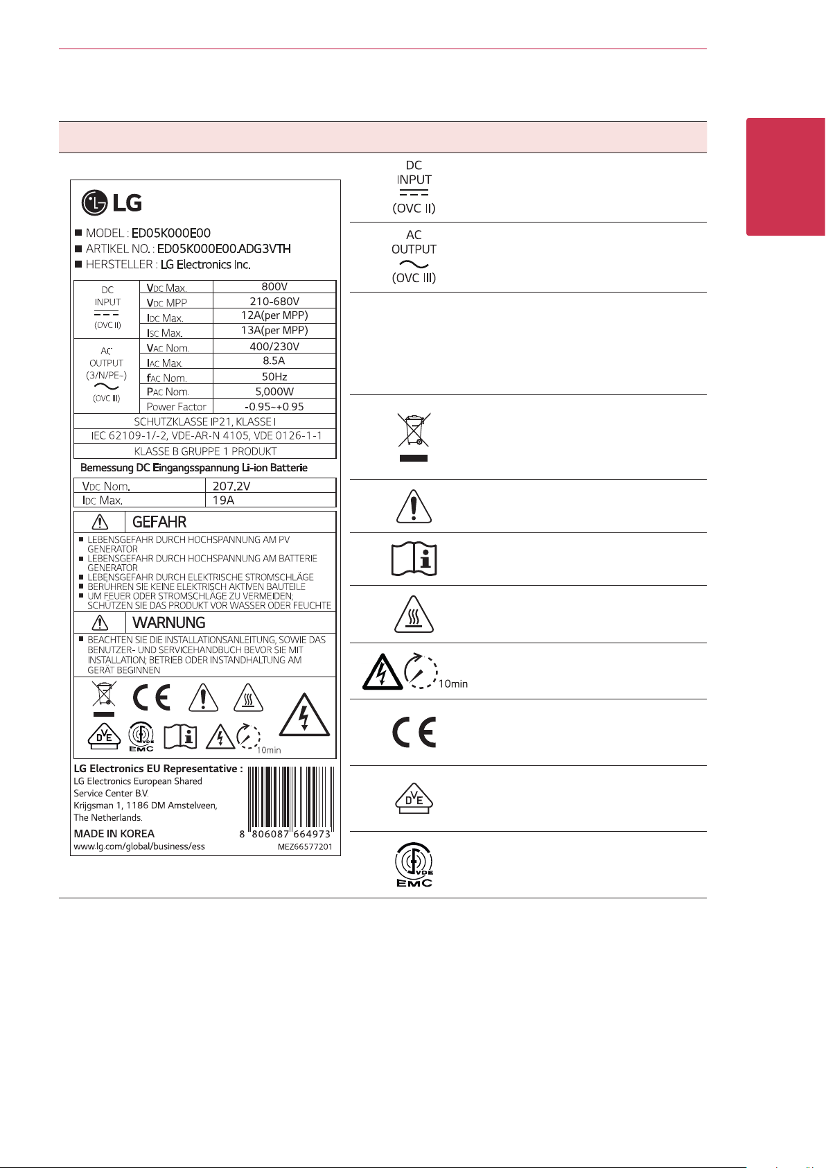
Symbol used on the label
Label Symbol Description
Direct current input
Three phase four wire alternating
current conductor
This product is protected against
insertion of ngers and will not
IP21
damaged during a specied test
in which it is exposed to vertically
dripping water.
This product should not be disposed
of with other household waste.
Disposal regulations should be
observed in this country.
Getting Started 7
1
Getting Started
Caution, risk of danger
Refer to the installation manual or
operating manual.
Caution, hot surface
Caution, risk of electric shock,
energy storage timed discharge
The relevant equipment complies
with the requirements in the EC
guidelines.
The relevant equipment complies
with the requirements of IEC
62109-1, IEC 62109-2.
The relevant equipment complies
with the requirements of EN
61000-6-3.
Page 8

Getting Started8
Abbreviations on this manual
Abbreviation Designation Explanation
ESS Energy Storage System Inverter system that stores energy into a battery and uses it.
1
Getting Started
PCS Power Conditioning
System
PV Photovoltaic Solar panel system that converts solar energy into direct
SOC State of charge Current state of a battery
BMS Battery Management
System
DC Direct Current -
AC Alternating Current -
DHCP Dynamic Host
Conguration
Protocol
LAN Local Area Network Network that interconnects computers within a limited area.
IP Internet Protocol A set of rules for sending data across a network
A device intended to convert DC electricity generated from PV
system to AC electricity and feed it to household appliances.
current electricity
Electronic system that manages a rechargeable battery.
Standardized network protocol used on Internet Protocol (IP)
networks for automatic distributing network conguration
parameters, such as IP addresses for interfaces and services.
Glossary
Terms Explanation
Azimuth In the Northern hemisphere, the azimuth angle indicates by how much degrees the
module surface deviates from a full south aspect. In the southern hemisphere, it indicates
the deviation from a full north aspect. The azimuth angle is counted with positive values
within the range from south (0°) to west (90°) and it counted with negative values within
the range from south (0°) to east (-90°).
Tilt angle The tilt angle indicates by how much degrees the tilt of the module surface deviates from
the horizontal.
PV module The PV module refers to a panel designed to absorb the sun’s rays as a source of energy
for generating electricity.
PV array Technical device for the conversion of solar energy into electrical energy. All serial and
parallel installed and connected to PV modules of a PV system are referred to as a PV
array.
Page 9
Unpacking
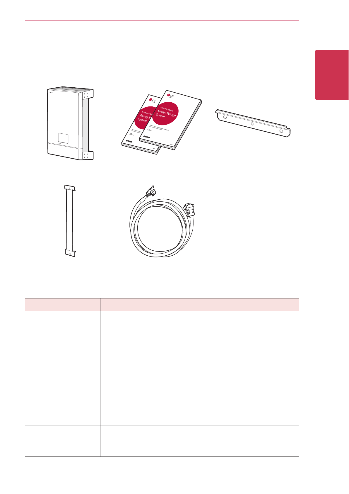
Contents of this product
Getting Started 9
1
Getting Started
Power conditioning system (1EA) Installation Manual and
Operating Manual (1EA each)
Middle wall bracket (1EA) BMS cable (3m, 1EA)
Additional components for installation
Applied to Additional Components
yStainless steel screws with diameter 6 mm - 8mm
Wall mounting
yAnchors
Upper wall bracket (1EA)
PV connections
Battery Connections
Power grid connections
Smart meter and internet
connections
yMC4 connectors
2
yLead wires with the cross-sectional area 2.5 mm
yLead wires with the cross-sectional area 2.5 mm
yWire-end-ferrules
yLead wires with the cross-sectional area 2.5 mm
green stripe cable)
yM4 size screws with spring washer
yTin plated round terminals with 4.0 mm or 4.5 mm of inner diameter
yWire-end-ferrules
yLAN cable
yRJ-45 plug
ySmart meter cable
- 6 mm
2
- 4 mm
2
- 6 mm2 (including yellow
2
2
Page 10
1
Getting Started
Getting Started10
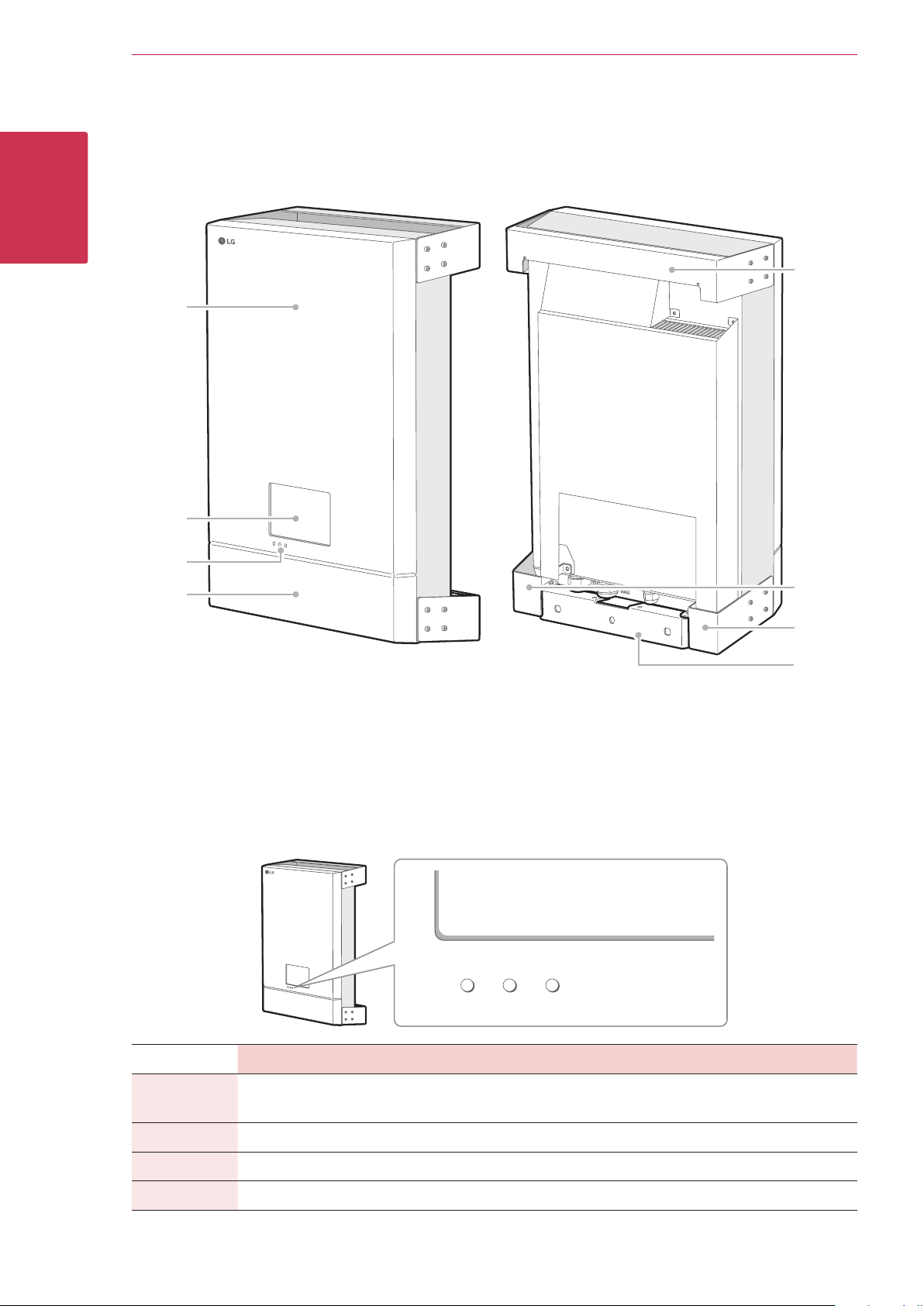
Name of each part
Front and Rear
E
A
B
C
D
Front Cover
A
LCD touch panel
B
LED Indications
C
Lower Cover
D
LED indications
Upper bracket connected part
E
Lower bracket connected part (Left)
F
Lower bracket connected part (Right)
G
Lower wall bracket
H
Power Solar Battery
F
G
H
Off
Green
Red (Blink)
Blue
Power Solar Battery
Power grid is not connected.
Power grid is connected. Energy is being generated. Battery is in charging
- Fault Fault
- - Battery is in discharging
Energy is not being
generated.
Battery is in stop mode
Page 11
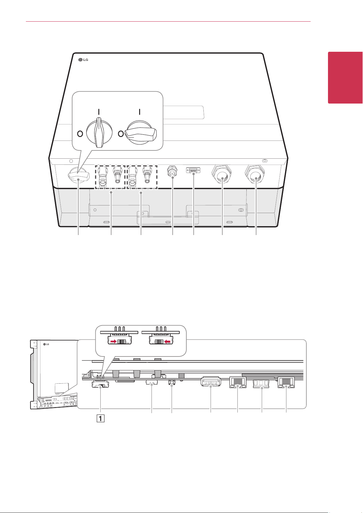
Lower parts
Getting Started 11
A B C D E F G
PV switch (DC Disconnect)
A
PV1(+ and -) connectors
B
PV2 (+ and -) connectors
C
Battery DC cable gland
D
OFFON
BMS control connector
E
Meter/LAN cable gland
F
AC grid cable gland
G
1
Getting Started
Inner parts (lower cover opened)
OFFON
A B C D E F G
Power Switch
A
Buzzer
B
RESET button
C
USB port
D
E
F
G
Ethernet port
Smart Meter connector
PCS port
Page 12
12 Installation
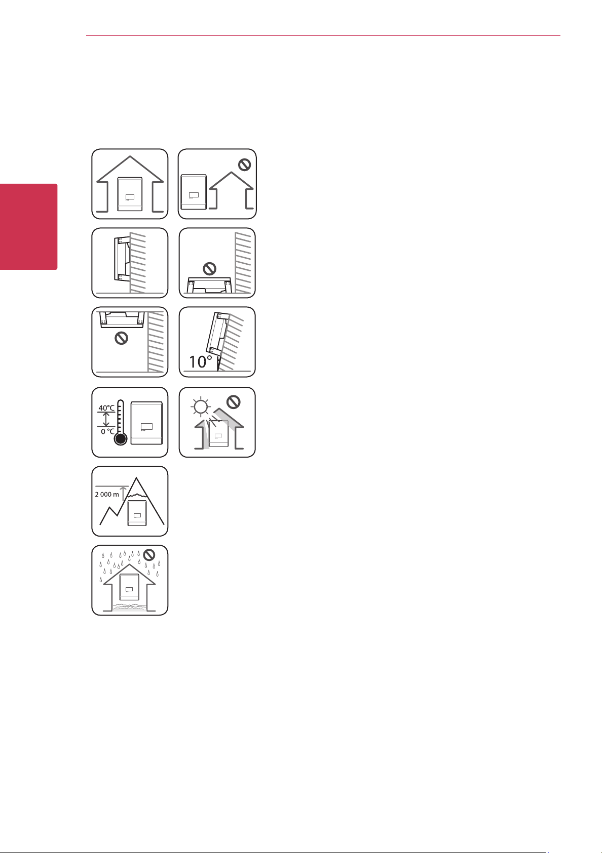
Choice of location
Mounting Location
2
Installation
yThis product is designed to be installed indoor use only. Do not
install this product outdoor.
yInstall this product on the place where PV cables, smart meter
cables, grid cables and battery cables are easily accessible.
yThis product is designed to be installed on the wall only. Do not
install this product on the ground.
yThe mounting surface must be able to support the weight of this
product (34 kg).
yDo not install the product on the ceiling.
yDo not install the product widthwise or install on a wall with lean
more than 10 degrees.
yDo not install the product tilting forward.
yInstall the product the connection side down.
yAppropriate operating temperature is from 0° C to 40° C.
yDo not install this product in the place exposed to the direct
sunlight.
yInstall the product in a clean, cool room.
This product must not be installed or used at altitudes above 2 000 m.
Do not install this product in places where ooding frequently occurs.
Page 13
Installation
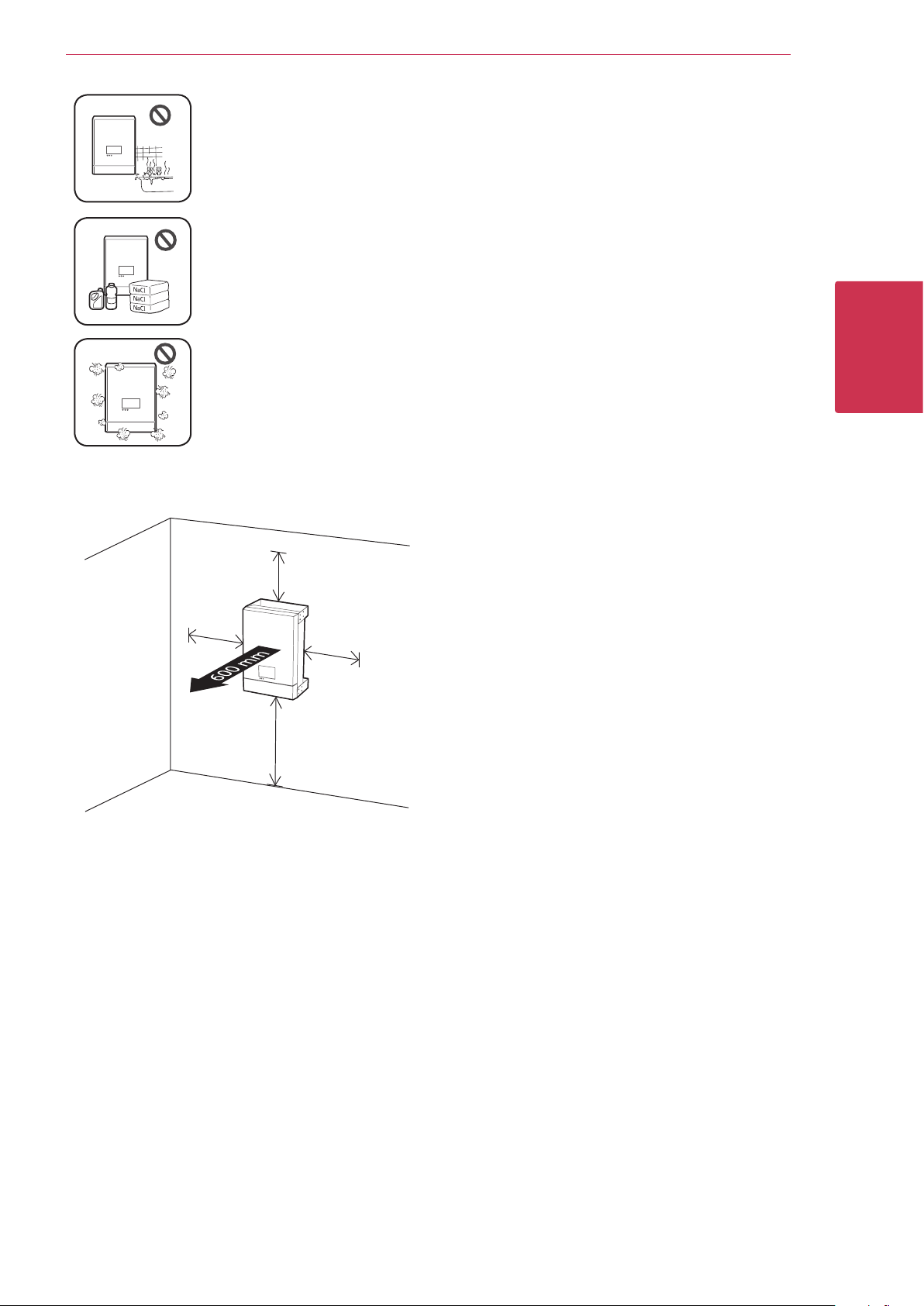
yDo not install this product to highly humid area such as bathroom.
yThis product generates low levels of noise at certain times, it should not be installed
close to living areas.
yNoise level may differ depending on the installed location.
yDo not install the product where there is vibration.
yDo not install this product in a place with ammonia, corrosive vapours, acids or salts.
yInstall this product out of reach from children and pet.
13
Do not install this product in places and environments subject to heavy build-up of dust.
Minimum clearance
300 mm
300 mm
300 mm
1000 mm
2
Installation
This product must be installed with clearance at the
left, right, top, bottom and front of the product as
shown in the gure.
Only the battery can be installed at the bottom
clearance space of the product. If you install the
battery unit at the bottom clearance space, leave the
clearance space between the battery and the product
more than 300 mm.
Page 14
14 Installation
NOTE
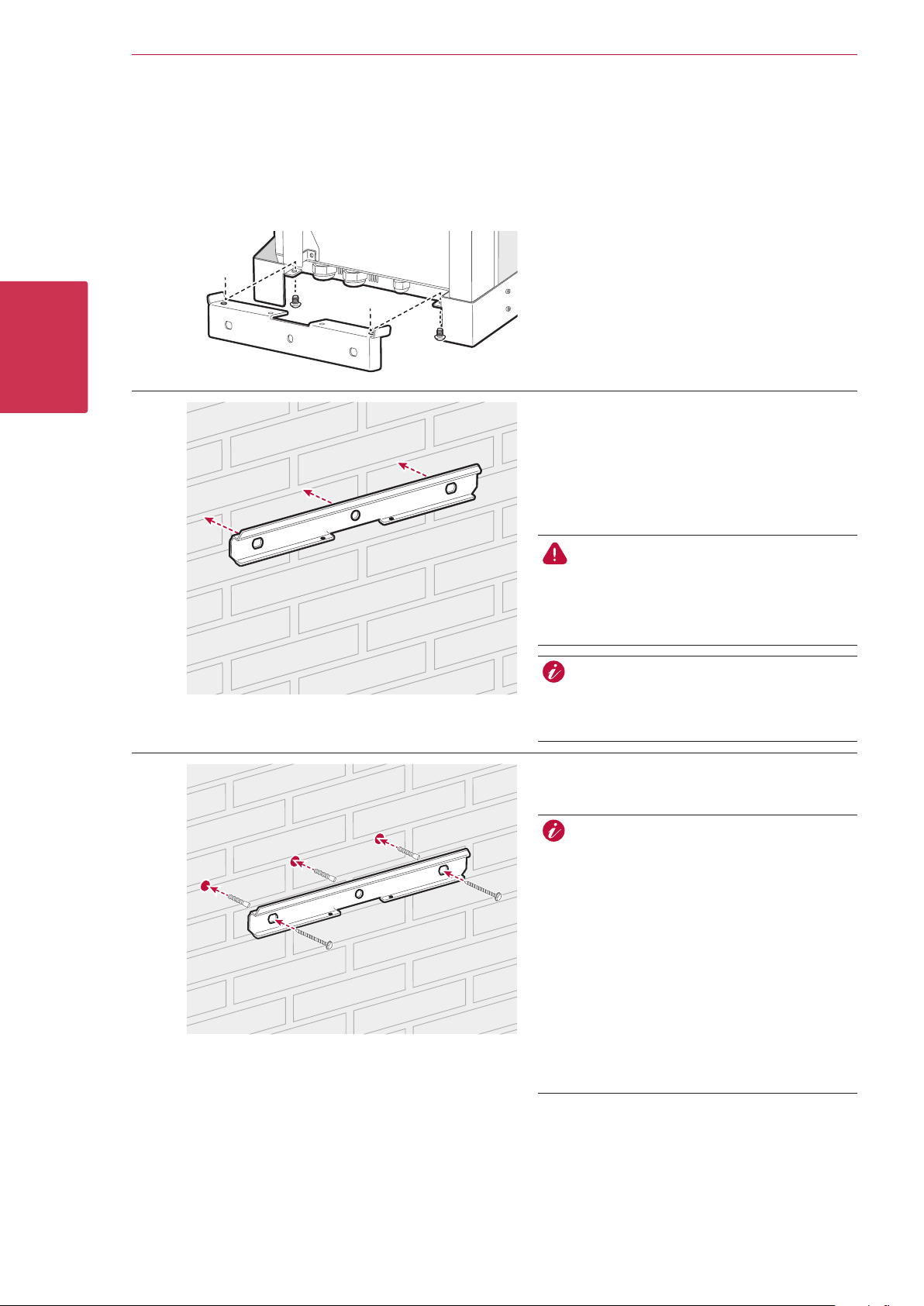
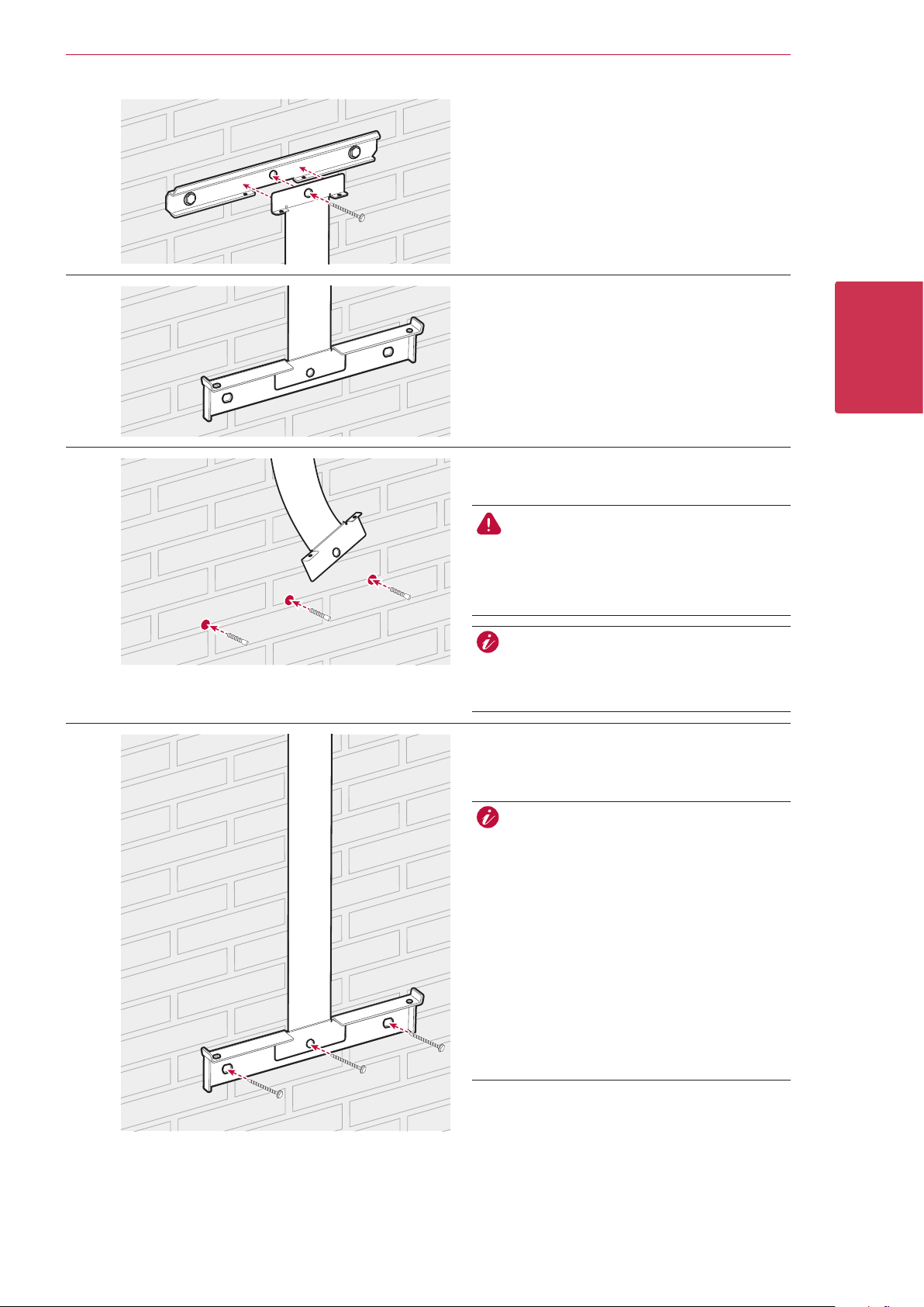
Wall Mounting
This product must be installed on the wall considering appropriate environments described in previous pages.
Follow the mounting instruction described below exactly and securely.
2
Installation
A
B
Disassemble the lower wall bracket from the
product.
Place the upper wall bracket on a wall where
meets every installation conditions and
clearance.
And indicate the positions to drill using a pencil
or the like. And drill holes on the indicated
positions.
WARNING
It is important to ensure the drilling locations
are not located on any electrical wiring within
the wall.
C
When attaching the wall bracket to a wall,
adjust the horizontal level using inclinometer.
Fix the upper wall bracket with screws and
anchors.
NOTE
yBefore xing the bracket screws, check
the horizontal level once again using
inclinometer.
yDepending on the surface, different screws
and anchors may be required for installing
the wall bracket. Therefore, these screws
and anchors are not content of the product.
The system installer is responsible for
selecting the proper screws and anchors.
yIt is recommended to use stainless steel
screws with diameter of 6-8 mm.
Page 15
Installation
15
D
E
F
Assemble the upper wall bracket and middle
wall bracket and x it with screw.
Assemble the lower wall bracket and middle
wall bracket. And indicate the positions to drill
using a pencil or the like.
After making indications, disassemble the
lower wall bracket.
2
Installation
Drill holes on the indicated positions and
attach the anchors.
WARNING
G
It is important to ensure the drilling locations
are not located on any electrical wiring within
the wall.
NOTE
When attaching the wall bracket to a wall,
adjust the horizontal level using inclinometer.
Assemble the lower wall bracket and middle
wall bracket. And x the lower wall bracket
with screws.
NOTE
yBefore xing the bracket screws, check
the horizontal level once again using
inclinometer.
yDepending on the surface, different screws
and anchors may be required for installing
the wall brackets. Therefore, these screws
and anchors are not content of the product.
The system installer is responsible for
selecting the proper screws and anchors.
yIt is recommended to use stainless steel
screws with diameter of 6-8 mm.
Page 16
16 Installation
2
Installation
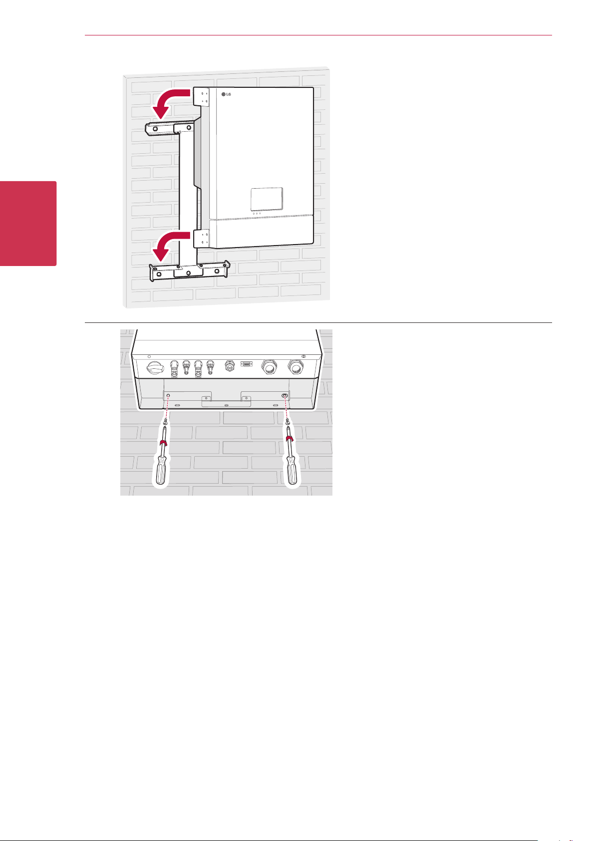
H
I
Hang this product to the upper wall bracket.
Make sure that at least two persons work
together to move the product.
Check the screw holes at the bottom are
matched with lower bracket holes correctly.
And x the product with screws removed from
the lower wall bracket in step 1.
Page 17

Connections
Connection Overview
Installation
17
2
Installation
Battery
PV Array 1
Power Grid
PV Array 2
Smart Meter
Internet
WARNING
y Electrical shock hazard. Do not touch uninsulated wires when the PCS cover is removed.
yBefore starting electrical cable connections or removing the cover, turn off the AC circuit breaker, PV switch
and DC circuit breaker of the battery. (In case of re-installation, turn them off and wait at least 10-minute
standby period of time for complete discharge within this product.)
yWhen the photovoltaic array is exposed to light, it supplies a DC voltage to the PCS.
CAUTION
yThe electrical installation of these PCS and battery must only be performed by electricians or technicians,
qualied to install PCS and battery.
yWhen removing the cover, make sure not to damage internal components.
Page 18

18 Installation
NOTE
PV array connections
You can connect up to two PV arrays directly to the MC4 connectors on this product.
WARNING
Make sure the AC circuit breaker, PV switch and DC circuit breaker of the battery are disconnected before
starting electrical cable connections.
CAUTION
yBefore connecting PV array, make sure that the open circuit voltage of PV array is less than 800V.
Otherwise this product could be damaged.
yDo not connect a ground to a PV+ or PV- connector. It may cause electric shock or the product may
permanently be damaged.
2
Installation
yPV modules shall have an IEC61730 Application Class A rating or equivalent.
yFor DC cables of PV connections, it is recommended to use the cross-sectional area of lead wire between
2.5mm
yUse MC4 branch connector if you want to use both PV1 and PV2 connectors together in order to connect
two PV arrays serially.
2
and 6 mm2.
PV1 connection
Connect DC cables of a PV array to PV1 connectors on this product.
PV array1
PV1+
PV2 connection
Connect DC cables of a PV array to PV2 connectors on this product.
PV array2
PV2+
PV1-
PV2-
Page 19

Installation
WARNING
yDo not mismatch the connection of the electric poles + to - and - to + when installing. It may cause electric
shock or the product may permanently be damaged.
yDo not connect the PV cable from one PV array to the PV1+, PV2- or PV1-, PV2+ connectors on the
product. It may cause electric shock or the product may permanently be damaged.
19
2
Installation
yDo not connect PV arrays in parallel connection to the one PV input on the product. It may cause electric
shock or the product may permanently be damaged.
Page 20

20 Installation
Battery connections
You can connect a battery to this product. The electricity generated from the connected PV array will be stored
in the battery.
The battery for this product are not included with this product package. Before connecting the battery to this
product, install the battery on the place where the battery cables are easily accessible to this product.
Refer to the installation manual of the battery for more information about battery installation.
WARNING
yMake sure the AC circuit breaker, PV switch and DC circuit breaker of the battery are disconnected before
starting electrical cable connections.
yBattery replacement can only be carried out by qualied personnel. If the battery needs to be changed, it
should be placed with a product which meets the manufacturer’s specications.
2
Installation
yDo not mismatch the connection of the electric poles + to - and - to + when installing. It may cause electric
shock or the product may permanently be damaged.
CAUTION
Incorrect battery polarity connection will damage the product seriously. This damage is not covered by the
warranty.
NOTE
The total length of DC battery cable and BMS cable must be 10 m or less.
DC cable connection
Connect the DC cable on the battery to the DC terminal on this product.
A
B
Disassemble the lower cover from the product.
Release the cap of battery DC cable gland.
Page 21

Installation
NOTE
NOTE
21
C
D
To
(+) terminal
(Red)
To
(-) terminal
(Black)
Insert the battery DC cables into the cap of
the cable gland and insert the cables into two
holes of the rubber tting one by one.
yFor DC cables of battery connections, the
cross-sectional area of lead wire between
2.5 mm2 and 4 mm2 is recommended.
yThe maximum cable diameter for the cable
gland is 4 mm. (including sheath)
2
Installation
Insert the battery DC cables through the
battery DC cable gland.
E
15 mm
Wire-end Ferrules
Battery DC cable
(A)
When inserting cables into the product, make
sure not to damage internal components.
Strip the battery DC cables and assemble wireend ferrules on each wire.
1. Strip a DC cable about 15 mm length and
insert a wire-end ferrule into the cable.
2. Crimp the ferrule end using wire-end ferrule
crimping tool (A).
NOTE
Cables and wire-end ferrules are not supplied
on this product package. The system
installer is responsible for selecting proper
components for the installation such as
cables and wire-end ferrules.
Page 22

22 Installation
(+)
2
Installation
F
G
Insert each wire-end to the corresponding
ferrule-hole in the Battery DC terminals and
tighten the cable tie securely.
Battery DC
Terminals
(–)
Red wire
CAUTION
Incorrect battery polarity will damage the
product. This damage is not covered by the
warranty.
Fasten the cap of cable gland to x the cable.
Black wire
H
Assemble the lower cover to the product.
And then x the screws in numbering order.
Battery communication connection
Connect the supplied BMS cable to the battery and connect the other end of the BMS cable to the product as
gure below. After making a connection, fasten the screws on the connector to x it.
Battery
Page 23

Installation
NOTE
Power grid connections
To use or sell the generated energy through power grid connection, you should connect power grid to this
product. This product converts DC electricity generated from PV array to AC electricity. The generated energy
can be sold to the electric utility or used for the household appliance.
WARNING
Make sure the AC circuit breaker, PV switch and DC circuit breaker of the battery are disconnected before
starting electrical cable connections. .
NOTE
yAC circuit breaker must be the current ratings of 16A.
yThis product can cause current with a DC component. Where a Residual Current-operated protective
(RCD) or monitoring (RCM) device is used for protection in case of direct or indirect contact, only an RCD
or RCM of Type A (or type B) is allowed on the supply side of this product.
yConnect the equipment grounding before connecting the AC wires to the grid.
Before making a power grid connection, other end of an AC cable should be connected to an AC circuit breaker
on the distribution box.
23
2
Installation
A
B
C
PE
Release the cap of AC cable gland.
NOTE
Select an appropriate size of sealing ring
inside the AC cable gland according to the
thickness of the AC cable.
Disassemble the lower cover from the product.
AC cableAC wires
Strip an AC cable about 200 mm length.
And cut wires about 50 mm except grounding
wire (PE).
50 mm
200 mm
yIt is recommended to use a yellow green
stripe wire for the PE grounding connection.
yFor AC wires of grid connections, it is
recommended to use the cross-sectional
area of lead wire between 2.5 mm
6 mm2.
yThe maximum cable diameter for the AC
cable gland is 19 mm. (including sheath)
2
and
Page 24

24 Installation
NOTE
2
Installation
D
E
Round
Terminal
(A)
15 mm
PE
Wire-end Ferrules
Insert an AC cable through the AC cable gland.
WARNING
Before connecting an AC cable, make sure
that the AC circuit breaker of the power grid is
turned off securely.
Insert the AC cable into the cap of cable gland
before inserting cable into the product.
Assemble wire-end ferrules and round terminal
on each wire.
1. Strip the grounding wire (PE) about 15 mm
and insert a round terminal into the wire.
Recommended round terminal : 4.0 mm or
4.5 mm
terminal
2. Crimp the round terminal using crimping tool
(A).
3. Strip remaining wires about 15 mm and
insert a wire-end ferrule into the wire.
4. Crimp the ferrule ends using crimping tool
(A).
inner diameter with tin plated
of
F
1 mm
NOTE
Cables, round terminal and wire-end ferrules
are not supplied on this product package. The
system installer is responsible for selecting
proper components for the installation.
PE
Connect the grounding wire (PE) to the
grounding connector. (Torque of 1.5 ± 0.3 N.m)
yConnect the equipment grounding before
connecting the AC wires to the AC circuit
breaker.
yScrew for grounding connection is not
supplied on this product package. Prepare
a M4 size screw with spring washer for the
grounding connection.
Page 25

Installation
25
G
H
Insert remaining wire-ends to the
corresponding ferrule-hole in the AC terminal.
L1
NOTE
yThe N (neutral) hole in the AC terminal must be connected to the N(neutral) terminal of the AC
circuit breaker on the distribution box correctly. Otherwise the product could be damaged seriously.
yThe PE (Protective Earth) grounding connector must be connected to the G (Grounding) terminal of
the distribution box correctly. Otherwise the product could be damaged seriously.
Assemble the lower cover to the product.
And then x the screws in numbering order.
L2
L3
N
2
Installation
I
Fasten the cap of cable gland to x the cable.
Page 26

26 Installation
Smart meter and internet connection
The smart meter connection is required to get information of energy ow. The Smart Meter for this product is
not included with this product package. Before connecting the smart meter to this product, install the smart
meter. Refer to installation manual of the smart meter for more information about smart meter installation.
Internet connection is required to use variety of functions such as network update, EnerVu monitoring system,
etc. You may need to contact your Internet service provider (ISP) to connect this product to the internet.
WARNING
Make sure the AC circuit breaker, PV switch and DC circuit breaker of the battery are disconnected before
starting electrical cable connections. .
2
Installation
A
B
C
Release the cap from the Meter/LAN cable gland.
Make cut openings on each hole of the rubber
tting using a scissors.
Insert the LAN cable, smart meter cable and
the additional grounding wire into the cap of
the cable gland and insert the cables into three
holes of the rubber tting one by one.
NOTE
LAN cable
Additional
Grounding wire
Meter cable
yFor additional grounding wire, the cross-
sectional area of lead wire between 2.5
2
mm
and 6 mm2 is recommended.
yThe cross-sectional area of the additional
grounding wire must be the same or larger
than the grounding wire (PE).
yRecommended color of additional grounding
wire is yellow green stripe.
yScrew for grounding connection is not
supplied on this product package. Prepare
a M4 size screw with spring washer for the
grounding connection.
yThe maximum diameter of each cable
for the holes on rubber tting is 5 mm.
(including sheath)
Page 27

Installation
NOTE
27
D
E
Disassemble the lower cover from the product.
Insert the cables into the product through
Meter/LAN cable gland.
The total length of smart meter cable and
LAN cable must be 30 m or less.
Strip the LAN cable and attach a RJ-45 plug at
the end of the cable.
Insert the LAN plug to the Ethernet port on the
product.
2
Installation
F
G
H
Detach the plug from smart meter connector.
Strip two wires of the smart meter cable and
insert stripped wire-ends to the corresponding
wire hole on the plug, making a match each A
and B.
Refer to installation manual of the smart
meter for more information about smart meter
installation.
Insert the plug to the smart meter connector.
Page 28

28 Installation
2
Installation
I
J
Strip the additional grounding wire about
15 mm and insert a round terminal into the
wire. And then connect the additional grounding
wire to the additional grounding connector
(mandatory, Torque of 1.5 ± 0.3 N.m)
NOTE
The additional grounding connector must be
connected to the G (Grounding) terminal of
the distribution box correctly. Otherwise the
product could be damaged seriously.
Assemble the lower cover to the product.
And then x the screws in numbering order.
K
Smart Meter and LAN connection diagram
Internet Router
(Hotspot)
Disconnection
S/W
Fasten the cap of cable gland to x the cable.
Internet
Smart Meter
Distribution
Box
Bi-Directional
Meter
Power
Grid
PV Array1
PV Array2
Load
1
Load2Load
3
When all the connections are nished, check the status in numbering order below.
1) Switch the DC circuit breaker of the connected battery to the ‘ON’ position.
2) Switch the AC circuit breaker to the ‘ON’ position.
3) Turn the PV switch of the PCS to the ‘ON’ position.
Page 29

Settings
Installer settings
When this product is turned on for the rst time, settings in [Installer settings] menu must be set by
authorized service personnel.
Before starting [Installer Settings], make sure that physical connection and installation are done as described
in this manual exactly and securely.
Basic operation
To enter [Installer Settings] menu, system requires installer password. Before setting installer settings menu,
input installer password.
29
A
B
C
Tab [ ] on the main screen and tab [Installer Settings]
option.
[Installer Log In] menu appears on the screen.
Input installer password and tab [LOG IN] to enter [Installer
Settings] menu.
Tab a desired menu option on the left side.
3
Settings
D
Tab a desired setting option and set the appropriate value.
Page 30

30 Settings
[Network] settings
If there is a DHCP server on the local area network (LAN) via wired connection, this product will be
automatically allocated an IP address. After making the physical connection, a small number of home networks
may require the network setting to be adjusted.
3
Settings
A
B
C
Tab [Network] on [Installer Settings]. Current status of the
network connection is displayed.
If you want to connect the EnerVu server, tab [Web server
data upload] to change to [On].
Tab [Web server data upload] again for turning off the option.
[On] : The energy data of the system is saved and uploaded to
the server in every 15 minutes.
[Off] : The energy data of the system is not saved. And it is not
uploaded to the server.
Tab [Test] to check the server connection.
If the [Web server data upload] option is not set to [On], the
data may not uploaded to the server.
Tab [Wired settings]. Wired connection options are displayed.
If [IP Setting] option in [Wired settings] tab is set to [Auto],
this product will be automatically allocated an IP address
from local area network (LAN) via wired connection. You
may need to set network connection manually depending on
the network conditions. In this case, tab [Auto] to change to
[Manual].
Fill in [IP address], [Subnet Mask], [Gateway] and [DNS
address] option manually.
NOTE
Notes on internet Connection:
yThis product does not support wireless network connection.
yMany network connection problems during set up can often be xed by re-setting the router or modem.
After connecting the product to the home network, quickly power off and/or disconnect the power cable
of the home network router or cable modem. Then power on and/or connect the power cable again.
yDepending on the internet service provider (ISP), the number of devices that can receive internet service
may be limited by the applicable terms of service. For details, contact your ISP.
yOur company is not responsible for any malfunction of this product and/or the internet connection
feature due to communication errors/malfunctions associated with your broadband internet connection,
or other connected equipment.
Page 31

NOTE
Notes on internet Connection:
ySome internet connection operations may not be possible due to certain restrictions set by the Internet
service provider (ISP) supplying your broadband Internet connection.
yA 10 Base-T or 100 Base-TX LAN port is required for wired connection to this product. If your internet
service does not allow for such a connection, you will not be able to connect this product.
yA DSL modem is required to use DSL service and a cable modem is required to use cable modem service.
Depending on the access method and subscriber agreement with your ISP, you may not be able to use
the internet connection feature contained in this product or you may be limited to the number of devices
you can connect at the same time. (If your ISP limits subscription to one device, this product may not be
allowed to connect when a PC has been already connected.)
yThe use of a “Router” may not be allowed or its usage may be limited depending on the policies and
restrictions of your ISP. For details, contact your ISP directly.
yTurn off all unused network equipment in your local home network. Some devices may generate network
trafc.
[PV/Meter] settings
You can check the PV and Meter information.
Settings
31
Tab [PV/Meter] on [Installer Settings]. PV and smart meter
information is displayed.
[PV], [PV1] and [PV2]
1. Select the currently selected value of each option to change. Input
menu appears on the screen.
2. Input the desired value.
3. Select [Accept] to complete the setting.
[Meter]
1. Select the currently selected value of each option to change. Input
menu appears on the screen.
2. Input the desired value.
3. Select [Accept] to complete the setting.
3
Settings
Page 32

32 Settings
[PCS/Battery] settings
You can set battery use and operation.
3
Settings
Tab [PCS/Battery] on [Installer Settings]. PCS and battery
information is displayed.
[PCS]
[PV Feed-in Limitation] is displayed. The value can be changed
manually.
1. Select the currently selected value. Input menu appears on the
screen.
2. Input the desired value.
3. Select [Accept] to complete the setting.
[Battery]
You can change [Use batteries] setting. Tab the switch to set [On] or
[Off]. If the setting is set to [Off], generated energy will not charge
the connected battery.
[Battery maker], [Operating range], [Winter Mode SOC] [Battery
Installation Date] and [Battery Capacity] can be set manually.
1. Select the currently selected value of each option to change. Input
menu appears on the screen.
2. Input the desired value.
3. Select [Accept] to complete the setting.
CAUTION
If the [Use batteries] setting is set to off or the system is turned off for a long period time, the battery can
be completely discharged and cannot be used anymore. Be sure not to stop using the battery for a long
period of time.
Page 33

Settings
[Operating Test] settings
This is the last stage at setting process. Before operating this product, [Operating Test] must be done for
checking all the systems are ready to run. If [Operating Test] is not proceeded, this product does not work.
33
A
B
Tab [Operating Test] on [Installer Settings]. The operating test
menu is displayed.
You should perform 4 operating tests. To start the test, tab
[START] of each test. Start the tests one by one from left.
Charging (Grid to Battery) : The operating test
for battery charging through power grid.
Charging (PV to Battery) : The operating test
for battery charging through PV.
Discharging (Battery to Grid): The operating
test for battery discharging to power grid.
Inverter (PV to Grid): The operating test for
converting PV’s DC power to AC power.
The result is displayed when each test is completed. When
there is no problem with the test, [Success] is displayed. When
[Fail] is displayed, tab each test result to display the detailed
information. Check and solve the error referring to the error
code in the information, and perform the test again. For
information on the error code, refer to page 40.
3
Settings
Page 34

34 Settings
NOTE
[Firmware/Reset] settings
Firmware Upgrade
You can upgrade the rmware to the latest version using USB storage device.
3
Settings
A
B
C
Tab [Firmware/Reset] on [Installer Settings]. [Firmware
Upgrade] tab and [Factory Reset] tab are displayed. For
rmware upgrade, select [Firmware Upgrade].
Before starting rmware upgrade, download the latest
rmware to a USB storage device and insert it into the USB
port on this product. Tab [UPGRADE] to start upgrade.
[Reboot] button is displayed when upgrade is completed.
Remove the USB storage device from this product and tab
[Reboot] to reboot the product.
Firmware upgrade must be done by the installer only. And rmware must not be distributed by installer.
Factory reset
You can reset the settings of the product to its original factory settings.
A
B
Tab [Firmware/Reset] on [Installer Settings]. [Firmware
Upgrade] tab and [Factory Reset] tab are displayed. Select
[Factory Reset].
You can reset this product to its original factory settings. All
the settings and system logs will be deleted after resetting.
Tab [Accept Reset]. A pop-up message appears on the LCD
screen.
Tab [Accept] to start factory resetting.
Page 35

[Change Password] settings
You can change the password for entering [Installer settings] menu.
Settings
35
A
B
Tab [Change Password] on [Installer Settings]. Change
Password menu is displayed.
Tab [Change]. Input menu for new password is displayed.
Tab
the new password. Select [OK]. The password is changed.
repeatedly to delete the current password and input
System Log
You can see the list of mode changes, system fault and system warning log.
Refer to page 40 for more information of error codes, messages and solutions.
A
The list of all notice occurring in this product during certain
period.
Tab [System Log] on [Installer Settings].
3
Settings
B
Tab current [Period] value and select the period using S or W.
Tab [Accept] to select the period. Tab [Search] to display the
list of the notice during the selected period.
: Goes to next page.
S
: Goes to previous page.
W
Page 36

36 Settings
EnerVu settings
To use the EnerVu web monitoring system, the product must be registered to the system server by the
installer. After registering, the user can check the variety of information such as system status, information,
report using LG EnerVu web monitoring system.
Preparation
yAn internet browser installed computer, tablet or mobile with internet access is needed to access EnerVu
web monitoring system.
yThis product must be connected to internet. Check [Network] setting menu in the LCD touch panel of the
product.
yThe system owner must create a LG ESS account before registering the product. Refer to ‘Creating a new
account (Owner)’ section below.
Creating a new account (Owner)
3
Settings
A
B
C
On your browser, visit LG EnerVu page at
http://enervu.lg-ess.com.
Select [Sign Up]. The [Accept Terms & Conditions] page
appears. Read the Terms & Conditions and Privacy Policy
carefully.
If you agree with every term and condition, click the [I Agree]
check box and select [AGREE].
The [Create Account] page appears.
Fill your e-mail address in [User ID] eld and select [CHECK
AVAILABILITY].
Fill in [Password], [Password conrm] and [Birthday] elds and
select [CONFIRM].
The E-mail conrmation page appears.
Page 37

Settings
37
D
E
F
A conrmation e-mail will be sent to your e-mail address.
On your e-mail, select [CONFIRM] to complete the e-mail
conrmation.
On the account creation page, select [CONFIRM] to complete
creating your account.
Select [SIGN IN] to go to the [SIGN IN WITH LG ACCOUNT]
page.
Input your [User ID] and [Password] and select [SIGN IN].
3
Settings
G
Available LG account services are displayed on the screen.
Page 38

38 Settings
Creating a new account (Installer)
3
Settings
A
B
C
On your browser, visit LG EnerVu page at
http://enervu.lg-ess.com.
Select [Installer]. The [Installer Sign In] page appears.
Select [Sign Up]. The [Sign Up] page appears.
Fill your mail address in [Email] eld and select [Check].
And then ll the [First Name] and [Last Name] elds.
Fill the required information on [Company Details] section.
And then read the [Installer Terms] and [Installer Privacy
Policy] carefully. If you agree with every terms and policies, click
[I agree] check box in each section. [Submit] button appears
on the screen.
D
Select [Submit] to complete creating an installer account.
Page 39

Registering the PCS (Installer)
Settings
39
A
B
C
On your browser, visit LG EnerVu page at
http://enervu.lg-ess.com.
Select [Installer]. The [Installer Sign In] page appears.
And then input the installer’s e-mail address and the password
and select [Installer Sign In].
If the installer does not have an account, select [Sign Up] and
make a new installer account.
Select [Activation] tab.
The [Add a New System] screen appears.
3
Settings
D
E
F
Fill every information in the [System Info] section and select
[Save] to save the information.
In the [ESS Info] eld, ll the product registration number and
select [Check]. The ESS information will automatically be lled.
Select [Save] to go to the next step.
Fill the every information In the [Owner] eld and select
[Save] to save the information.
And Select [Activation] at the bottom of the page to nish
the activation process.
Page 40

40
Troubleshooting
Error Codes and Messages
PCS error codes
Code Message Description Solution
4
Troubleshooting
P301 BMS CAN Comm Fault Communication error with the
connected battery for over 10
seconds.
P302 PMS Comm Fault Communication error on PCS
system.
P303 DSP SCI Comm Fault Communication error with
the processing unit for over a
minute.
P304 Meter Comm Fault Communication error with the
smart meter.
P305 Grid Relay(L1-1) F Grid relay is not operable.
(L1-1)
P306 Grid Relay(L2-1) F Grid relay is not operable.
(L2-1)
P307 Grid Relay(L3-1) F Grid relay is not operable.
(L3-1)
P308 Grid Relay(N-1) F Grid relay is not operable.
(N-1)
P309 Grid Relay(L1-2) F Grid relay is not operable.
(L1-2)
Contact service center.
Fault Reset & Restart
Contact service center
Stop, Fault Reset & Restart
Automatically reboot within a
minute.
Automatically reboot within a
minute.
Automatically reboot within a
minute.
Automatically reboot within a
minute.
Automatically reboot within a
minute.
P310 Grid Relay(L2-2) F Grid relay is not operable.
(L2-1)
P311 Grid Relay(L3-2) F Grid relay is not operable.
(L3-2)
P312 Grid Relay(N-2) F Grid relay is not operable. (N-2) Automatically reboot within a
P315 PCS IGBT Fault The PCS IGBT is not operable. Automatically reboot within a
P316 ESS Fan Fault The cooling fan in the product is
in fault.
P317 Fault Reset Fail Fault reset has been failed 3
times.
P318 Fuction Safety F The processing unit has a
hardware fault.
P320 DSP SCI Comm Error Communication error with
the processing unit for over 5
seconds.
P321 Grid Conn Fault Incorrect power grid connection
has detected.
Automatically reboot within a
minute.
Automatically reboot within a
minute.
minute.
minute.
Automatically reboot within a
minute.
Contact service center.
Automatically reboot within a
minute.
Automatically reboot within a
minute.
Contact service center.
Page 41

Troubleshooting
41
P201 PV A Over Volt P Voltage level of PV A is higher
than the limitation.
P202 PV B Over Volt P Voltage level of PV B is higher
than the limitation.
P203 PV A Over Curr P Current level of PV A is higher
than the limitation.
P204 PV B Over Curr P Current level of PV B is higher
than the limitation.
P205 PV Insulation P Insulation resistance level on PV
is lower than the limitation.
P206 Batt Over Volt P Voltage level of the battery is
higher than the limitation.
P207 Batt Over Curr P Current level of the battery is
higher than the limitation.
P208 DC Link Over Volt P Voltage level of the DC Link is
higher than the limitation.
P209 Grid Under Volt P Voltage level of the grid is lower
than the limitation.
Automatically reboot within a
minute.
Automatically reboot within a
minute.
Automatically reboot within a
minute.
Automatically reboot within a
minute.
Automatically reboot within a
minute.
Automatically reboot within a
minute.
Automatically reboot within a
minute.
Automatically reboot within a
minute.
Automatically reboot within a
minute.
P210 Grid Over Volt P Voltage level of the grid is
higher than the limitation.
P211 Grid Over Curr P Current level of the grid is
higher than the limitation.
P212 Grid Under Freq P Frequency level of the grid is
lower than the limitation.
P213 Grid Over Freq P Frequency level of the grid is
higher than the limitation.
P214 Residual Curr P Residual current level is higher
than the limitation
P215 Over Temperature P The PCS temperature is higher
than the limitation.
P216 Anti Islanding P There was a power failure. Automatically reboot within
P217 Grid Avg Volt P An average voltage level within
10 minutes is higher than the
limitation.
Automatically reboot within a
minute.
Automatically reboot within a
minute.
Automatically reboot within a
minute.
Automatically reboot within a
minute.
Automatically reboot within a
minute.
Automatically reboot within a
minute.
a minute. after the power
recovery.
Automatically reboot within a
minute.
4
Troubleshooting
P218 Grid DC Curr P DC offset current is added on
Grid
P219 PCS Starting Error The Error is happened when
PCS is running in the starting
sequence.
P220 Batt Under Volt P Voltage level of the battery is
lower than the limitation
P101 Batt Over Volt W Voltage level of Battery is
higher than the limitation.
Automatically reboot within a
minute.
Automatically reboot within a
minute.
Contact service center
Warning
Page 42

42
Troubleshooting
P102 Batt Over Curr W Current level of Battery is
higher than the limitation.
P103 Batt Under Volt W Voltage level of Battery is lower
than the limitation.
P104 PV Low Power W PV power is lower than
limitation.
Battery error codes
B301 Cell OverVolt F Voltage level of battery cell
is higher than the protection
limitation.
B302 Cell OverVolt_2 F Voltage level of battery cell
is higher than the second
protection limitation.
B303 Cell Under Volt F Voltage level of battery cell
is lower than the protection
limitation.
B304 Cell Volt Imbal F Voltage differences between
the battery cells are higher
than 3.5 V.
Warning
Warning
Warning
Contact service center.
Contact service center.
Contact service center.
Contact service center.
4
Troubleshooting
B305 Pack Over Volt F Voltage level of battery pack
is higher than the protection
limitation.
B306 Pack Under Volt F Voltage level of battery pack
is lower than the protection
limitation.
B307 Over Charge Curr F Current level of charging is
higher than the protection
limitation.
B308 Over Dischar Curr F Current level of discharging
is higher than the protection
limitation.
B309 Over Temperature F The battery temperature is
higher than the limitation.
B310 Under Temperature F The battery temperature is
lower than the limitation.
B311 Temp Deviation F Temperature differences
between the battery are over
10 degrees.
B312 Curr Sensor Offset Fault has been detected on the
current sensor.
Contact service center.
Contact service center.
Contact service center.
Contact service center.
Contact service center.
Contact service center.
Contact service center.
Contact service center.
B313 PCS-RBMS LOC Communication error has been
detected between the battery
and the PCS.
B314 Ext 12V Power Error The power is not supplied to
the battery from the PCS.
B315 RBMS-MBMS LOC Internal communication error
has been detected.
Contact service center.
Contact service center.
Contact service center.
Page 43

Troubleshooting
B316 Curr Sensor Line E Current sensor line error Contact service center.
B317 Temp Sensor Error Temperature sensor error Contact service center.
43
B318 MBMS ASIC LOC Internal error has been
detected.
B319 RBMS Ref V Error Voltage level of the battery
management system is higher
than the protection limitation.
B320 MBMS Ref V Error Voltage level of the battery
management system is lower
than the protection limitation.
B321 MBMS Volt Circuit F Cannot measure the cell
voltage of battery management
system.
B322 RBMS Flash CRC E Internal memory error has been
detected.
B323 MBMS CVSE Error has been detected on cell
voltage sensing line.
B324 Cell Sum Volt Dev Voltage deviation of battery
cells differ from the sum of the
reference value.
B325 RBMS-RBMS LOC Internal communication error
has been detected.
Contact service center.
Contact service center.
Contact service center.
Contact service center.
Contact service center.
Contact service center.
Contact service center.
Contact service center.
B326 MCU Error An error has been detected on
processing unit.
B327 RAM Check An error has been detected on
RAM.
B328 ROM Check An error has been detected on
ROM.
B329 MBMS Init Error An error has been detected
when resetting the battery
management system.
B330
B331 MBMS Version Error Battery version error Contact service center.
B332 MBMS EEPROM E An error has been detected on
B101 Cell Over Volt W Voltage level of battery cell
B102 Cell Under Volt W Voltage level of battery cell
OBD Fail
OBD Fail Fault Contact service center.
EEPROM.
is higher than the protection
limitation.
is lower than the protection
limitation.
Contact service center.
Contact service center.
Contact service center.
Contact service center.
Contact service center.
Stop battery powering and
Standby
Stop battery powering and
stand-by.
4
Troubleshooting
B103 Cell Volt Imbal W Voltage differences between
the battery cells are higher
than 3.5 V.
B104 Pack Over Volt W Voltage level of battery pack
is higher than the protection
limitation.
Stop battery powering and
stand-by.
Stop battery powering and
stand-by.
Page 44

44
Troubleshooting
B105 Pack Under Volt W Voltage level of battery pack
is lower than the protection
limitation.
B106 Over Charge Curr W The SOC level of the battery
is higher than the protection
limitation.
B107 Over Disch Curr W The SOC level of the battery
is lower than the protection
limitation.
B108 Over Temperature W The battery temperature is
higher than the limitation.
B109 Under Temperature W The battery temperature is
lower than the limitation.
B110 Temp Deviation W Temperature differences
between the batteries are over
5 degrees.
yFirmware version, Error codes and Fault conditions on the lists can be accessed on the display. And those can
also be accessed from the server.
Stop battery powering and
stand-by.
Stop battery powering and
stand-by.
Stop battery powering and
stand-by.
Stop battery powering and
stand-by.
Stop battery powering and
stand-by.
Stop battery powering and
stand-by.
4
Troubleshooting
If you have any technical problem or question, please contact the service center below.
Address : LG Electronics Deutschland GmbH Berliner Straße 93
40880 Ratingen
Germany
Tel. : + 0049 18 06 807 020
E-Mail: b2b.service@lge.de
Page 45

Appendix
Maintenance
Cleaning the product
To clean this product, use a soft, dry cloth. If the surfaces are extremely dirty, use a soft cloth lightly moistened
with a mild detergent solution. Do not use strong solvents such as alcohol, benzene, or thinner, as these might
damage the surface of the product.
Do not use volatile liquids such as insecticide spray near this product. Wiping with strong pressure may
damage the surface. Do not leave rubber or plastic products in contact with the product for a long period of
time.
When cleaning the air duct, shut off all the systems including PCS, PV module, battery, AC circuit breaker. After
that, open the lower cover of the PCS and remove dust on the air duct using a soft brush.
Inspecting regularly
It is recommended to check the operating status and connection status once a year. Contact authorized dealer
or where you purchased.
45
Disposing the product
When the product reached to the end of its service life or defect beyond repair, dispose the product according
to the disposal regulations for electronic waste in your area. Disposing the product must be carried out by
qualied personnel only. Contact authorized dealer or where you purchased.
Disassemble the product
You may need to disassemble the product when you move or dispose the product. You must keep the
procedure as described, otherwise there may have electric shock or serious burns due to the high voltages.
WARNING
yAll work on the product disassembly must be carried out by qualied personnel only.
yThere is high possibility of electric shock or serious burns due to the high voltages in power conditioning
circuits.
yWear rubber gloves and protective clothing (protective glasses and boots) when working on high voltage/
high current systems such as PCS and battery systems.
A
Tab [ ] on the main screen and tab [Start].
A notice appears on the screen.
Tab [Accept] to stop operation.
5
Appendix
B
Turn off the DC disconnect switch on the
bottom of the product. And turn off the DC
circuit breaker of the connected battery. Refer to
battery manual for more information of turning
off the DC circuit breaker.
Page 46

46
Appendix
Turn off the AC circuit breaker in the distribution box.
C
And wait at least 10-minute standby period of time to complete discharging this product.
D
Disconnect the Ethernet, smart meter, BMS cables from the product.
E
Disconnect the PV1 and PV2 connector from the product.
F
Disconnect the battery DC cables from the product. Use the appropriate size of a at-head
G
screwdriver when disconnecting.
Disconnect the AC and grounding cable from the product. Use the appropriate size of a screwdriver
H
when disconnecting.
I
Disassemble the lower cover from the product.
Assemble the lower cover to the product.
And then x the screws in numbering order.
5
Appendix
J
K
Remove the screws from the lower wall bracket.
Remove the product from the wall. Make sure that
at least two persons work together to move the
product.
Page 47

Checking the PCS setting information
Installer can see current PCS settings as below.
Appendix
47
A
B
Tab [ ] on the main screen and tab [Installer Settings]
option.
[Installer Log In] menu appears on the screen.
Input ‘pcs’ and tab [space] for more than 2 seconds in [Installer
Log In] menu.
[PCS Settings Information] appears on the screen.
NOTE
yAll the values on the [PCS Settings Information] list can
not be edited by user or installer.
NOTE
yViewable information names are listed below -
Grid Normal Voltage, Grid Normal Frequency, Grid Over/Under Voltage, Grid Over/Under Frequency,
Grid Over Current, DCLINK Over Voltage, Battery Over/Under Voltage, Battery Over Current,
PV1 Over/Under Voltage, PV1 Over Current, PV2 Over/Under Voltage, PV2 Over Current,
Heat-sink Over Temperature, PV Insulation Resistance, Operating Grid Maximum/Minimum Voltage,
Relay on Grid Voltage, Operating Grid Maximum/Minimum Frequency, Operating BAT Maximum/Minimum
Voltage, Residual Maximum/Minimum Current, RESTART TIME, TRIP TIME, Country Standard Set,
PV1 Capacity, PV2 Capacity, PV Feed-in Limit, Battery SOC Maximum/Minimum, Battery SOC Minimum
Alert
5
Appendix
Page 48

48
Appendix
Specications
General
Dimensions (W x H x D) 493 mm x 670 mm x 185 mm
Net weight (approx.) 34 kg
Operating temperature 0 °C to 40 °C
Operating humidity 60 %
Max. efciency (PV to grid) 95.7 %
AC input/output
Rated grid voltage 3-NPE 400 V / 230 V
Power factor range -0.95 — +0.95
AC voltage range (L-N) 184 — 264.5 V
5
Appendix
AC voltage range (L-L) 319 — 458 V
Short circuit current (Isc) 12 A
Current Inrush 73 Aac-peak / 0.05 ms
Max. fault current 83 Aac-peak / 20 ms
Max. output overcurrent protection 12 A
Frequency (frequency range) 50 Hz (47.5 - 51.5 Hz)
Max. AC power (from PV) 5,000 W
Max. AC power (from battery) 3,000 W
Max. output current 8.5 A
Total harmonic distortion 5%
Phases 3
DC input/output
Max. input voltage 800 V
Max. DC power 6,600 W
Input voltage range MPPT
at rated AC output power
210-680 V
Number of MPPT 2
Number of string per MPPT 1
Max. input current per MPPT 12 A
Backfeed current 0 A
Short circuit current (Isc) per MPPT 13 A
Page 49

Battery input / output
Battery manufacturer LG Chem
Battery model name ED00064CN00.ADG3TUH
Battery capacity 6.4 kWh
Rated voltage 207.2 V
Operating voltage range 168 V to 232.4 V
Constant current / constant voltage
Standard charging condition
Max. charging/discharging current 19 A
0.3 C (9.45 A) current, charging voltage
232.4 V (at 25 °C)
Appendix
49
Standard charging
conditions (CC-CV)
Standard
discharging
conditions (CC)
Charging current 0.3C (9.45A)
Condition for
termination
Discharging current 0.3C (9.45A)
Condition for
termination
232.4 V
168 V
Feature & function
Noise emission 40 dB
Cooling Forced convection
Topology Transformerless
Degree of protection IP21
Max. permissible value of relative humidity
(non-condensing)
Display 7” Touch LCD
Certication IEC/EN 62109-1/-2, VDE-AR-N 4105, VDE 0126-1-1
Web monitoring service Available
yDesign and specications are subject to change without notice.
85 % (Climate class 3K5)
5
Appendix
Page 50

Page 51

Page 52

 Loading...