

LG DVD-6054, DVD-6184, DV-7511-E-6-S, DV-7811-E-6-S Service manual

DVD VIDEO PLAYER
SERVICE MANUAL
MODELS : DVD6054/DVD6184
(DV7511E6S/DV7811E6S)
MODELS : DVD6054/DVD6184(DV7511E6S/DV7811E6S)
SERVICE MANUAL
P/NO : 3829RHP017A
SEPTEMBER, 2003
Printed in Korea
CAUTION
BEFORE SERVICING THE UNIT, READ THE “SAFETY PRECAUTIONS”
IN THIS MANUAL.
DVD6054 DVD6184

SECTION 1
SUMMARY
CONTENTS
PRODUCT SAFETY SERVICING GUIDELINES FOR VIDEO PRODUCTS ............. 1-2
SERVICING PRECAUTIONS .................................................................................................. 1-3
• General Servicing Precautions
• Insulation Checking Prodedure
• Electrostatically Sensitive Devices
SPECIFICATIONS ...................................................................................................................... 1-4
1-2
IMPORTANT SAFETY NOTICE
This manual was prepared for use only by properly trained audio-video service
technicians.
When servicing this product, under no circumstances should the original
design be modified or altered without permission from LG Electronics
Corporation. All components should be replaced only with types identical to
those in the original circuit and their physical location, wiring and lead dress
must conform to original layout upon completion of repairs.
Special components are also used to prevent x-radiation, shock and fire hazard. These components are indicated by the letter “x” included in their component designators and are required to maintain safe performance. No deviations
are allowed without prior approval by LG Electronics Corporation.
Circuit diagrams may occasionally differ from the actual circuit used. This way,
implementation of the latest safety and performance improvement changes
into the set is not delayed until the new service literature is printed.
CAUTION: Do not attempt to modify this product in any way. Never perform
customized installations without manufacturer’s approval. Unauthorized modifications will not only void the warranty, but may lead to property damage or
user injury.
Service work should be performed only after you are thoroughly familiar with
these safety checks and servicing guidelines.
GRAPHIC SYMBOLS
The exclamation point within an equilateral triangle is intended to
alert the service personnel to important safety information in the
service literature.
The lightning flash with arrowhead symbol within an equilateral triangle is intended to alert the service personnel to the presence of
noninsulated “dangerous voltage” that may be of sufficient magnitude to constitute a risk of electric shock.
The pictorial representation of a fuse and its rating within an equilateral triangle is intended to convey to the service personnel the
following fuse replacement caution notice:
CAUTION: FOR CONTINUED PROTECTION AGAINST RISK
OF FIRE, REPLACE ALL FUSES WITH THE SAME TYPE AND
RATING AS MARKED NEAR EACH FUSE.
SERVICE INFORMATION
While servicing, use an isolation transformer for protection from AC line shock.
After the original service problem has been corrected, make a check of the following:
FIRE AND SHOCK HAZARD
1. Be sure that all components are positioned to avoid a possibility of adjacent
component shorts. This is especially important on items trans-ported to and
from the repair shop.
2. Verify that all protective devices such as insulators, barriers, covers, shields,
strain reliefs, power supply cords, and other hardware have been reinstalled
per the original design. Be sure that the safety purpose of the polarized line
plug has not been defeated.
3. Soldering must be inspected to discover possible cold solder joints, solder
splashes, or sharp solder points. Be certain to remove all loose foreign particles.
4. Check for physical evidence of damage or deterioration to parts and components, for frayed leads or damaged insulation (including the AC cord), and
replace if necessary.
5. No lead or component should touch a high current device or a resistor rated
at 1 watt or more. Lead tension around protruding metal surfaces must be
avoided.
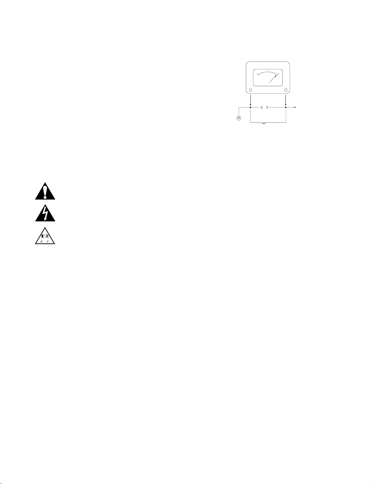
6. After reassembly of the set, always perform an AC leakage test on all
exposed metallic parts of the cabinet (the channel selector knobs, antenna
terminals, handle and screws) to be sure that set is safe to operate without
danger of electrical shock. DO NOT USE A LINE ISOLATION TRANSFORMER DURING THIS TEST. Use an AC voltmeter having 5000 ohms per
volt or more sensitivity in the following manner: Connect a 1500 ohm, 10
watt resistor, paralleled by a .15 mfd 150V AC type capacitor between a
known good earth ground water pipe, conduit, etc.) and the exposed metallic parts, one at a time. Measure the AC voltage across the combination of
1500 ohm resistor and .15 mfd capacitor. Reverse the AC plug by using a
non-polarized adaptor and repeat AC voltage measurements for each
exposed metallic part. Voltage measured must not exceed 0.75 volts RMS.
This corresponds to 0.5 milliamp AC. Any value exceeding this limit constitutes a potential shock hazard and must be corrected immediately.
TIPS ON PROPER INSTALLATION
1. Never install any receiver in a closed-in recess, cubbyhole, or closely fitting
shelf space over, or close to, a heat duct, or in the path of heated air flow.
2. Avoid conditions of high humidity such as: outdoor patio installations where
dew is a factor, near steam radiators where steam leakage is a factor, etc.
3. Avoid placement where draperies may obstruct venting. The customer
should also avoid the use of decorative scarves or other coverings that
might obstruct ventilation.
4. Wall- and shelf-mounted installations using a commercial mounting kit must
follow the factory-approved mounting instructions. A product mounted to a
shelf or platform must retain its original feet (or the equivalent thickness in
spacers) to provide adequate air flow across the bottom. Bolts or screws
used for fasteners must not touch any parts or wiring. Perform leakage tests
on customized installations.
5. Caution customers against mounting a product on a sloping shelf or in a tilted position, unless the receiver is properly secured.
6. A product on a roll-about cart should be stable in its mounting to the cart.
Caution the customer on the hazards of trying to roll a cart with small casters across thresholds or deep pile carpets.
7. Caution customers against using extension cords. Explain that a forest of
extensions, sprouting from a single outlet, can lead to disastrous consequences to home and family.
A.C. Voltmeter
1500 OHM
10 WATT
Place this probe
on each exposed
metal part.
Good Earth Ground
such as the Water
Pipe, Conduit, etc.
0.15uF
PRODUCT SAFETY SERVICING GUIDELINES FOR VIDEO PRODUCTS

1-3
SERVICING PRECAUTIONS
CAUTION : Before servicing the DVD covered by this service
data and its supplements and addends, read and follow the
SAFETY PRECAUTIONS. NOTE : if unforeseen circumstances create conflict between the following servicing precautions and any of the safety precautions in this publications, always follow the safety precautions.
Remembers Safety First:
General Servicing Precautions
1. Always unplug the DVD AC power cord from the AC
power source before:
(1) Removing or reinstalling any component, circuit board,
module, or any other assembly.
(2) Disconnection or reconnecting any internal electrical
plug or other electrical connection.
(3) Connecting a test substitute in parallel with an elec-
trolytic capacitor.
Caution : A wrong part substitution or incorrect
polarity installation of electrolytic capacitors may result
in an explosion hazard.
2. Do not spray chemicals on or near this DVD or any of
its assemblies.
3. Unless specified otherwise in this service data, clean
electrical contacts by applying an appropriate contact
cleaning solution to the contacts with a pipe cleaner,
cotton-tipped swab, or comparable soft applicator.
Unless specified otherwise in this service data, lubrication
of contacts is not required.
4. Do not defeat any plug/socket B+ voltage interlocks with
whitch instruments covered by this service manual might
be equipped.
5. Do not apply AC power to this DVD and/or any of its
electrical assemblies unless all solid-state device heat
sinks are cerrectly installed.
6. Always connect test instrument ground lead to the
appropriate ground before connection the test instrument
positive lead. Always remove the test instrument ground
lead last.
Insulation Checking Procedure
Disconnect the attachment plug from the AC outlet and turn
the power on. Connect an insulation resistance meter(500V)
to the blades of the attachment plug. The insulation resistance between each blade of the attachment plug and accessible conductive parts (Note 1) should be more than 1Mohm.
Note 1 : Accessible Conductive Parts including Metal panels, Input terminals, Earphone jacks, etc.
Electrostatically Sensitive (ES) Devices
Some semiconductor (solid state) devices can be damaged
easily by static electricity. Such components commonly are
called Electrostatically Sensitive (ES) Devices. Examples of
typical ES devices are integrated circuits and some field
effect transistors and semiconductor chip components.
The following techniques should be used to help reduce the
incidence of component damage caused by static electricity.
1. Immediately before handling any semiconductor component or semiconductor-equipped assembly, drain off any
electrostatic charge on your body by touching a known
earth ground. Alternatively, obtain and wear a commercially available discharging wrist strap device, which
should be removed for potential shock reasons prior to
applying power to the unit under test.
2. After removing an electrical assembly equipped with ES
devices, place the assembly on a conductive surface such
as aluminum foil, to prevent electrostatic charge buildup or
exposure of the assembly.
3. Use only a grouned-tip soldering iron to solder or unsolder
ES devices.
4. Use only an anti-static solder removal device. Some
solder removal devices not classified a “anti-static” can
generate electrical charges sufficient to damage ES
devices.
5. Do not use freon-propelled chemicals. These can
generate electrical charge sufficient to damage ES
devices.
6. Do not remove a replacement ES device from its protec
tive package until immediately before you are ready to
install it. (Most replacement ES devices are packaged with
leads electrically shorted together by conductive foam,
aluminum foil, or comparable conductive material).
7. Immediately before removing the protective material from
the leads of a replacement ES device, touch the protective
material to the chassis or circuit assembly into which the
device will be installed.
Caution : Be sure no power is applied to the chassis or
circuit, and observe all other safety precautions.
8. Minimize bodily motions when handling unpackaged
replacement ES devices. (Normally harmless motion such
as the brushing together of your clothes fabric or the lifting
of your foot from a carpeted floor can generate static electricity sufficient to damage an ES device.)

1-4
SPECIFICATIONS
• GENERAL
Power requirements AC 120V, 60Hz
Power consumption 14W
Dimensions(approx.) 430 x 43 x 242mm (W/h/d)
Weight(approx.) 2.34kg
Operating temperature 5˚C to 35˚C (41˚F to 95˚F)
Operating humidity 5% to 90%
• SYSTEM
Laser Semiconductor laser, wavelength 650nm
Signal system PAL/NTSC
Frequency response DVD (PCM 96kHz): 8Hz to 44kHz
DVD (PCM 48kHz): 2Hz to 22kHz
CD: 8Hz to 20kHz
Signal-to-noise ratio More than 100dB (ANALOG OUT connectors only)
Harmonic distortion Less than 0.008%
Dynamic range More than 100dB(DVD)
More than 95dB(CD)
• OUTPUTS
VIDEO OUT 1 V (p-p) 75 Ω, sync negative, RCA jack x 1 (TO TV)
Audio output (digital audio) 0.5 V (p-p), 75 Ω, RCA jack x 1
Audio output (analog audio) 2.0 Vrms (1 kHz, 0 dB), 600 Ω,
RCA jack (L, R) x 1 (TO TV)

2-1
SECTION 2
CABINET & MAIN CHASSIS
CONTENTS
1. EXPLODED VIEWS ................................................................................................................2-2
1. Cabinet and Main Frame Section ...........................................................................................2-2
2. Packing Accessory Section....................................................................................................2-5

2-2
EXPLODED VIEWS
1. Cabinet and Main Frame Section
463
463
250
A00
463
463
300
283
280
A42
A49
A47
A48
A44
A43
A46
260
261
261
463
320
463
467
463
465
452
SCART&5.1CH
MODEL
ONLY
OPTIONAL PART
A
5
4
3
2
1
BCD

2-3
• Cabinet and Main Frame Section• Cabinet and Main Frame Section Part List
S AL LOCA.NO PART NO(LG) A B DESCRIPTION SPECIFICATION REMARKS
ASSEMBLY PARTS SECTION
A42 6871R-5725A O PWB(PCB) ASSEMBLY,TOTAL DV7000S 5TOOL KEY SH
A42 6871R-5728A O PWB(PCB) ASSEMBLY,TOTAL DV7000S 8TOOL KEY SH
A43 3501RF3007C O BOARD ASSEMBLY DVD DV7811E4M HA3GLL
A43 3501RF6694F O BOARD ASSEMBLY DVD DV7511E6L HA8PLL
A44 3141R-D003F O CHASSIS ASSEMBLY DV7510E LSI,MTK 55MM NSP
A44 3141R-D004F O CHASSIS ASSEMBLY DV7810E MTK 43MM
A46 6885R-1015D O SUB PWB(PCB) ASSEMBLY DV7511E6S HA8PLL
A46 6885R-1015J O SUB PWB(PCB) ASSEMBLY DV7811E6S HA8PLL
A47 6871R-7604C O PWB(PCB) ASSEMBLY,TOTAL DV7000S SMPS SH 220V(CE)
A47 6871R-7604D O PWB(PCB) ASSEMBLY,TOTAL DV7000S LSI SMPS SH 220V (CE)
A48 6871R-7601C O O PWB(PCB) ASSEMBLY,TOTAL DV7000S MTK SH SCART
A49 6871R-5715A O PWB(PCB) ASSEMBLY,TOTAL DV7000S 5TOOL TIMER SH
A49 6871R-5718A O PWB(PCB) ASSEMBLY,TOTAL DV7000S 8TOOL TIMER SH
PARTS SECTION
250 3110R-D001A O CASE DV7000 PRESS 430-55(A288G)
250 3110R-D004A O CASE DV7000 PRESS 43MM A288G
260 3140R-D002A O O CHASSIS DV7000 PRESS MAIN NSP
261 5040R-0069D O O RUBBER FOOT(SILICONE SPONGE DS-08 T=
280 3721R-F306F O PANEL ASSEMBLY,FRONT[NORMAL PA DV7511E6L HA8PLL NSP
280 3721R-F318C O PANEL ASSEMBLY,FRONT[NORMAL PA DV7811E4M HA3GLL NSP
283 3581R-T068B O DOOR ASSEMBLY TRAY DV7500 (CHINA)
283 3581R-T069A O DOOR ASSEMBLY TRAY DV7800 (SPRAY)
300 6410RCHX03A O O POWER CORD CE-503/JL201B H03VVH2-F 2X0.75
320 3720R-D072F O PANEL,VIDEO DVD DV7510E PRESS LSI,MTK 55MM
320 3720R-D074F O PANEL,VIDEO DVD DV7810E PRESS MTK 43MM
SCREW
452 353-051A O SCREW SPECIAL
452 353-051A O SCREW SPECIAL
463 353-051G O O SCREW,DRAWING + 2 D3.0 L8.0 MSWR3/FN TB ROUN
465 353-046K O O SCREW SPECIAL (3X10 B.K)
467 353-046N O O SCREW,DRAWING SPECIAL(3X8 BK.)
MODELS:(A)DV7511E6S(DVD6054) (B)DV7811E6S(DVD6184)

3. Packing Accessory Section
BATTERY
808
PACKING SHEET
804
PACKING
OPTIONAL PARTS
803
806
OWNER'S MANUAL
CABLE DIN
810
CABLE ASS'Y
801
REMOCON
900
BOX CARTON
802
PACKING
803
811
812
PLUG ASS'Y 1WAY(YELLOW)
PLUG ASS'Y 2WAY
2-4
• Packing Accessory Section Part List
S AL LOCA.NO PART NO(LG) A B DESCRIPTION SPECIFICATION REMARKS
801 3835RS0063W O INSTRUCTION ASSEMBLY DVD DV7511E6S HA8PLL
801 3835RS0064A O INSTRUCTION ASSEMBLY DVD DV7811E6S HA8PLL
802 3890R-H803L O O BOX DV7511E6M HA8PLL SWW3-A 0.870
803 3920R-E066A O O PACKING,CASING DV7000 0.02 68 EPS 10 1165 238
804 292-053B O O BAG SOFT(MIDI) NSP
808 841-0021 O O BATTERY,MN ER03X HI WATT 1.5V .MA/H AAA
810 6851RP0003N O O CABLE ASSY,RF DVD CABLE ASSY,RCA USING AREA
811 6611R1G001A O O PLUG ASSY 1WAY YELLOW GLOBAL
812 6611R2G001A O O PLUG ASSY 2WAY RED/WHITE GLOBAL
900 6711R1P063A O O REMOTE CONTROLLER ASSEMBLY N6 UNIFIED DV7520E LG W/O DISC
MODELS:(A)DV7511E6S(DVD6054) (B)DV7811E6S(DVD6184)

3-1
SECTION 3
ELECTRICAL
CONTENTS
DVD PART
ELECTRICAL TROUBLESHOOTING GUIDE & WAVEFORMS
.................................. 3-2
1. System Clock X501 (27Mhz) ................................................................................................. 3-2
2. Initializing between MPEG and SDRAM .............................................................................. 3-2
3. Initializing between MPEG and Flash .................................................................................. 3-3
4. Reference Voltage 1............................................................................................................... 3-3
5. Reference Voltage 2............................................................................................................... 3-4
6. Checking the initial step of M/D Ass’y ................................................................................ 3-4
7. Checking the Video Signal ................................................................................................... 3-5
8. Checking the first step of servo (1) ..................................................................................... 3-5
9. Checking the second step of servo (2) ............................................................................... 3-6
10. Checking the output of Audio signal................................................................................. 3-6
11. Checking the reset port....................................................................................................... 3-7
12. Checking the focus & tracking servo ................................................................................ 3-7
13. Checking the track jump..................................................................................................... 3-8
14. The status of CD_LD and DVD_LD in the PLAY MODE ................................................... 3-8
15. The status Focus and spindle motor................................................................................. 3-9
16. DATA STREAM ..................................................................................................................... 3-9
17. Input Clock to IC202 .......................................................................................................... 3-10
18. Tray Open and Close......................................................................................................... 3-10
19. Focus Drive signal(FACT) ................................................................................................. 3-11
20. Signals for Front micom ................................................................................................... 3-11
21. FACT and FE for DVD9 (Dual disc) .................................................................................. 3-12
22. System clock of MPEG IC................................................................................................. 3-12
BLOCK DIAGRAMS ................................................................................................................ 3-13
1. DVD Overall Block Diagram................................................................................................ 3-13
2. SERVO Block Diagram........................................................................................................ 3-14
3. MPEG Block Diagram.......................................................................................................... 3-15
4. AUDIO Block Diagram......................................................................................................... 3-16
CIRCUIT DIAGRAMS.............................................................................................................. 3-17
1. POWER(SMPS) CIRCUIT DIAGRAM................................................................................... 3-17
2. RF SERVO CIRCUIT DIAGRAM........................................................................................... 3-19
3. SYSTEM CIRCUIT DIAGRAM .............................................................................................. 3-21
4. AUDIO & JACK CIRCUIT DIAGRAM................................................................................... 3-23
5. TIMER/5.1CH CIRCUIT DIAGRAM....................................................................................... 3-25
• CIRCUIT VOLTAGE CHART .................................................................................................. 3-27
PRINTED CIRCUIT DIAGRAMS.......................................................................................... 3-31
1. MAIN P.C.BOARD ................................................................................................................. 3-31
2. KEY P.C.BOARD................................................................................................................... 3-33
3. TIMER P.C.BOARD ............................................................................................................... 3-33
4. SCART P.C.BOARD.............................................................................................................. 3-35
4. POWER(SMPS P.C.BOARD ................................................................................................. 3-36

3-2
DVD PART
ELECTRICAL TROUBLESHOOTING GUIDE & WAVEFORMS
1. System Clock X501 (27Mhz)
IC501
X501
MPEG
(STI5589)
NORMAL
1) MPEG IC start oscilating
after being installed VCC
ABNORMAL
1) Logo Picture doesn’t appear
2) Initial step fail
* Initial step : power cord in -> green LED ->
red LED -> power key input -> Logo picture
6.5 Vp-p
X501 : 27 Mhz X501 : there is distortion
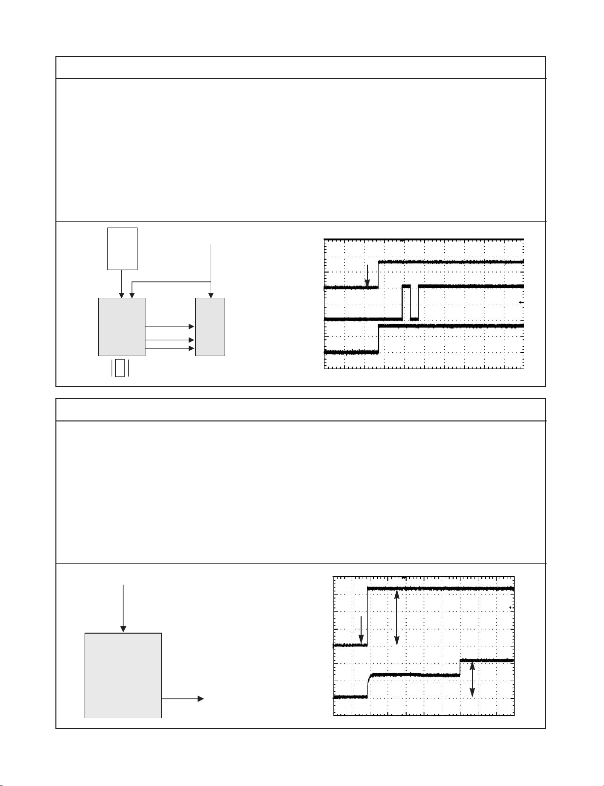
IC502
SDRAM
Front
µ-com
X501
/M-RESET
SMI_CLK
L507
IC501
MPEG
(STI5589)
1) MPEG IC start oscilating(27Mhz)after being
installed VCC
2) MPEG IC and DSP IC get the /M - RESET signal from front µ-com and they are initialized.
3) And then, MPEG IC generate SMI_CLK and
send to SDRAM
4) MPEG IC and SDRAM are synchronized by
SMI_CLK, they communicate between.
If oscilation(27Mhz) don’t appear, check
The X-TAL and VCC and replace MPEG IC.
If SMI_CLK don’t appear, first cut the SMI_CLK
line (remove L507) and recheck.
Don’t appear -> check MPEG IC or replace
Appear -> check the SDRAM or replace
/M-RESET
Reset Time
Power
Cord in
X501
(27 Mhz)
SMI_CLK
(133 Mhz)
2. Initializing between MPEG and SDRAM
3-3
IC503
Flash
ROM
IC901
Front
µ-com
X501
(27Mhz)
/M-RESET
WE
VCC
data
address
IC501
MPEG
(STI5589)
1) MPEG IC start oscilating(27Mhz) after being
installed VCC
2) MPEG IC is initialized by /M - RESE T
3) MPEG IC send the WE(read/write) signal before
communicating with FLASH ROM
WE signal should be confirmed by Flash or the
next step will not continue.
As that result, the initial step(power cord in ->
green LED -> red LED -> standby) will fail.
If WE signal doesn’t appear, check the VCC and
replace the Flash ROM…
VCC
Power
Cord in
/M-RESET
WE
3. Initializing between MPEG and Flash
VCC (3.3V)
V-REFD (2.1V)
9 PIN
10 PIN
IC202
DSP
(STL6316)
1) There is one kinds of reference voltage on DSP
IC
2) These are outputed from DSP IC and 2.1V is
used as reference of Pick - up
If these reference voltage don’t appear, All kinds of
servo control will fail.
So, should be checked first of all Check the DSP
IC and replace…
3) The reference voltage of DSP is 1.65V for inside
of IC L6316, but we can cheek the voltage only
by TP.
TP211 is for tracking error and TP212 is for focusing error.
VCC
3.3V
2.1V
Power
Cord in
VREF2
4. Reference Voltage 1

3-4
Pick-Up
TACT
A/B/C/D
Reference
2.1V
Reference
2.7V
IC201
DSP
(MN103S)
IC201
Motor
Drive
We can see how the reference voltage,
mentioned previous page, will work on servo
control..
1) The DC level of RF signal from P/up is 2.1V
2) The DC level of TE and FE is 1.65V
3) Correct DC level of these signal make servo
work normally.
Even though, the reference voltage come out
correctly from DSP,
If A/B/C/D are not biased by 2.1V, and checking
the P/up is needed.
If the DC level of TE is not 1.65V, check DSP
and replace it…
In case of FE, procedure is same
FE
1.65V
TE
A/B/C/D
1.65V
2.1V
5. Reference Voltage 2
CLOSE
-SW
LIMIT
-SW
PMD01 PMD02
FM+
LD-CD
Q203
IC202
DSP
M/D
ASSY
IC201
Motor
Drive
PMD03
Let’s look over the initial action of M/D...
1) When the tray is closed, CLOSE-SW should
be changed from 5V to 0V and DSP need to
detect this change
2) Feeding Motor move the P/up to inner area until
the LIMIT SW is detected
3) After DSP detect the LIMIT SW, DVD laser is
turned on and go to the next step
4) if there is a DISC on the tray, the RF will be
detected by the DVD laser and go to next step..
Check the CLOSE-SW and LIMIT-SW
if anything of the both is not detected, the next
step won’t go on. This means that even though
there is a DISC on the tray the DISC will not
rotate.
FM+
CLOSE-SW
P/up move
to inner area
Limit sw
detect
DVD LD on
Tray close
LIMIT-SW
DVD-LD
6. Checking the initial step of M/D Ass’y

3-5
Check the followings
1) Check the video output mode. if the output
mdoe is progressive - on, there is no composite signal.
the output mode should be changed to
progressive - off
2) Check the buffer IC and MPEG, and then
replace.
175 Ohm
Composite out
34 pin
IC403
23Pin
STI5589
(MPEG)
buffer
DC 0V
15.7 Khz
DC0.3V
31.3 Khz
Composite signal is normal --> Screen display OK Composite signal is abnormal -->there is no screen on TV
7. Checking the Video Signal
81
82
IC501
MPEG
DSP-RST
PC[o]
IC202
DSP IC
IC203
MOTOR
AMP IC
Let’s look over the initial step of DSP
1) First. DSP IC receive the DSP - Reset from
MPEG
2) This reset signal get DSP initialized and DSP is
ready to do first step for servo
3) PC[o] from DSP is the test signal for checking
the PLL- loop
4) after checking the PLL-loop, the second step is
followed. the second step will be explained on
next page…..
if PC[o] doesn’t appear, check DSP and
replace.
/DSP-Reset
Vcc(3.3V)
50ms
DSP Reset period
PC[o]
8. Checking the first step of servo (1)

3-6
M/D
ASSY
LD-DVD
PMD03
IC202
DSP
Let’s look over the initial step of servo
1) when the tray is closed, first of all, it should be
checked whether there is disc or not on tray
2) DVD laser is turn on and the lense is moved. if
there is a disc on tray, RF signal will appear
3) next, it should be confirmed which disc is that.
CD or DVD.
4) the following step will be done continuously
DVD -Laser on -> move up/down in according to
disc type, there will be RF signal…
5) after confirming disc, CD or DVD laser turn on
and focus servo is executed…
the below picture is related signals when CD
disc is inserted
DVD laser on
CD laser on
PI
CD/DVD
LD-DVD
LD-CD
4)
9. Checking the second step of servo (2)
DAC_PCMOUT
IC402
OPAMP
DAC_PCM_CLK
DAC_SCLK
DAC_LRCK
Analog
audio
IC501
MPEG
(STI5589)
AUDIO
DAC
(PCM1742)
IC401 is called as Audio DAC, DAC means DigitalAnalog Convertor.
This IC receives digital signal from MPEG and convert digital signal to analog signal, so we can hear
sound…
IC401 is connected with OP - AMP and an analog
Audio signal is amplified at the OP - A MP.
because the analog audio signal from DAC is a
very low level.
DAC_PCM_CLK : this is the system clock for
IC401
DAC_SCLK : this is standard clock to synchronize
the audio serial data
DAC_LRCK : R-chanel and L-chanel are selected
among the audio serial data by this
DAC_PCMOUT3 : serial audio data
DA_XCK
DA_BCK
DA_LRCK
DA_DATA
10. Checking the output of Audio signal

3-7
Pin 81 of IC202, pin 124, 186 of IC501 and pin 12 of IC503 are related to RESET.
We can know whether IC is intialized or not through those ports.
The waveform shows the status when the reset signal works normally.
If the /M-RESET is abnormal, then check the front u-com(IC901) and replace it
/M-RESET (Pin124 of IC501)
DSP_RST (Pin 81 of IC202)
3.3V power input
The waveform when power on
11. Checking the reset port
Waveforms as below are regarding focusing and tracking servo normally.
FE and TE signal are generated in IC202 and output at pin55, pin54 of IC202,(TP212, TP211)
respectively.
FE
IC202 Pin55
(TP212)
TE(TP211)
IC202 Pin54
12. Checking the focus & tracking servo

3-8
TE and TACT signals are output respectively from pin 54 and pin 34 of IC 202 during a normal play.
SLED signal is output pin 29 of IC 202 and flow into pin 15 and pin 18 of IC 201 to operate a sled motor
when to skip chapters or to scan.
IC202
pin34
IC202
pin54
IC202
pin29
IC202
pin34
IC202
pin54
IC202
pin29
The waveform during a normal play The waveform when to skip or scan
13. Checking the track jump
This is the waveform of FE and collector
outputs of Q205 and Q206 when to play DVD
This is the waveform of FE and collector outputs
of Q205 and Q206 when to play CD
The waveforms as below indicate “COLLECTOR” outputs of Q205 and Q206,
respectively when to play DVD and CD
IC202
pin55
(TP212)
Q206
COLLECTOR
Q205
COLLECTOR
IC202
pin115
Q206
COLLECTOR
Q205
COLLECTOR
14. The status of CD_LD and DVD_LD in the PLAY MODE
DVD LD ON
DVD LD OFF
CD LD ON

3-9
The waveform is to display F+ signal from pin 9 IC201 and SPM+ from pin 10 IC201.
F+ is used to control a focus actuator of pick - up and SPM+ is used to operate a spindle motor.
So, we can know the position of the acuator and the speed and rotating direction of the spindle
motor through those signals.
IC201
pin 9
IC202
pin 28
The waveform F+ and SPM+ in the PLAY Mode
15. The status Focus and spindle motor
This waveforms are showing “The Downloading serve program”.
The must important thein of the download process is the timing.
The servo program must be downloaded before the second DSP reset.
DSP_Reset(IC501 pin186 to IC202 pin81)
/MRESET
IIC_DATA(IC501 pin194 to IC202 pin69)
DSP_Reset active Low
IIC_CK(IC501 pin195 to IC202 pin68)
16. DATA STREAM
 Loading...