

LG DU62SX40D Users manual

Test Report No.: GETEC-E3-05-023
FCC Class B Certification
APPENDIX H
: USER’S MANUAL
EUT Type: 62” DLP Projection TV
FCC ID: BEJDU62SX40D

DLP Projection TV
LG Electronics U.S.A., Inc.
TM
R
TruSurround XT
Please read this manual carefully and completely before
operating your TV.
Retain this manual for future reference.
Record model number and serial number of the TV in the
spaces provided below.
See the label attached on the back cover and relate this
information to your dealer if you require service.
Model Number :
Serial Number :
OWNER’S MANUAL
MODEL: DU-52SX40D/52SX4D-UB
DU-62SX40D/62SX4D-UB
WARNING/CAUTION:
TO REDUCE THE RISK OF ELECTRIC SHOCK DO NOT REMOVE COVER (OR BACK). NO USER
SERVICEABLE PARTS INSIDE. REFER TO QUALIFIED SERVICE PERSONNEL.
The lightning flash with arrowhead symbol, within an equilateral triangle, is intended to alert the user to
the presence of uninsulated “dangerous voltage” within the product’s enclosure that may be of sufficient magnitude to constitute a risk of electric shock to persons.
The exclamation point within an equilateral triangle is intended to alert the user to the presence of
important operating and maintenance (servicing) instructions in the literature accompanying the appliance.
WARNING/CAUTION:
TO PREVENT FIRE OR SHOCK HAZARDS, DO NOT EXPOSE THIS PRODUCT TO RAIN OR MOISTURE.
POWER CORD POLARIZATION:
CAUTION: TO PREVENT ELECTRIC SHOCK, MATCH WIDE BLADE OF PLUG TO WIDE SLOT, FULLY
INSERT.
ATTENTION: POUR ÉVITER LES CHOCS ÉLECTRIQUES, INTRODUIRE LA LAME LA PLUS LARGE
DE LA FICHE DANS LA BORNE CORRESPONDANTE DE LA PRISE ET POUSSER JUSQU’AU FOND.
NOTE TO CABLE/TV INSTALLER:
This reminder is provided to call the CATV system installer’s attention to Article 820-40 of the National
Electric Code (U.S.A.). The code provides guidelines for proper grounding and, in particular, specifies that
the cable ground shall be connected to the grounding system of the building, as close to the point of the
cable entry as practical.
REGULATORY INFORMATION:
This equipment has been tested and found to comply with the limits for a Class B digital device, pursuant to Part
15 of the FCC Rules. These limits are designed to provide reasonable protection against harmful interference in
a residential installation. This equipment generates, uses and can radiate radio frequency energy and, if not
installed and used in accordance with the instructions, may cause harmful interference to radio communications.
However, there is no guarantee that interference will not occur in a particular installation. If this equipment does
cause harmful interference to radio or television reception, which can be determined by turning the equipment off
and on, the user is encouraged to try to correct the interference by one or more of the following measures:
- Reorient or relocate the receiving antenna.
- Increase the separation between the equipment and receiver.
- Connect the equipment into an outlet on a circuit different from that to which the receiver is connected.
- Consult the dealer or an experienced radio/TV technician for help.
Any changes or modifications not expressly approved by the party responsible for compliance could void the
user’s authority to operate the equipment.
CAUTION:
Do not attempt to modify this product in any way without written authorization from LG Electronics. Unauthorized modification could void the user’s authority to operate this product.
COMPLIANCE:
The responsible party for this product’s compliance is:
LG Electronics U.S.A., Inc
1000 Sylvan Avenue, Englewood Cliffs, NJ 07632
1-201-816-2000
http://www.lgusa.com
WARNING
RISK OF ELECTRIC SHOCK
DO NOT OPEN
/CAUTION
W
W
arning/Caution
arning/Caution
Warning/Caution
DLP Projection TV

Warning
TV Guide On Screen Notices for U.S.A.
TV Guide On Screen Notices for U.S.A.
In the United States, the TV GUIDE and other related marks are registered marks of Gemstar-TV Guide International, Inc.
and/or one of its affiliates. In Canada, TV GUIDE is a registered mark of Transcontinental Inc., and is used under license by
Gemstar-TV Guide International, Inc.
The TV Guide On Screen system is protected by one or more of the following issued United States patents 6,498,895,
6,418,556, 6,331,877; 6,239,794; 6,154,203; 5,940,073; 4,908,713; 4,751,578; 4,706,121.
The TV Guide On Screen system is manufactured under license from Gemstar-TV Guide International, Inc. and/or one of its
affiliates.
Digital Cable Compatibility
Digital Cable Compatibility
This digital television is capable of receiving basic analog, digital basic and digital premium cable television programming by
direct connection to a cable system providing such programming. A security card provided by your cable operator is required
to view encrypted digital programming. Certain advanced interactive digital cable services such as video-on-demand, cable
operator enhanced program guide, and data enhanced television service may require the use of a set top box. For more
information contact your local cable operator.
Use of the CableCARD
TM
TradeMark.
“CableCARD
TM
is a trademark of Cable Television Laboratories, Inc.”
Owner’s Manual
Safety Instructions
IMPORTANT SAFETY INSTRUCTIONS
Important safety instructions shall be provided with each apparatus. This information shall be given in a separate booklet or
sheet, or be located before any operating instructions in an instruction for installation for use and supplied with the apparatus. This information shall be given in a language acceptable to the country where the apparatus is intended to be used. The
important safety instructions shall be entitled “Important Safety Instructions”. The following safety instructions shall be included where applicable, and, when used, shall be verbatim as follows. Additional safety information may be included by adding
statements after the end of the following safety instruction list. At the manufacturer’s option, a picture or drawing that illustrates the intent of a specific safety instruction may be placed immediately adjacent to that safety instruction :
1. Read these instructions.
2. Keep these instructions.
3. Heed all warnings.
4. Follow all instructions.
5. Do not use this apparatus near water.
6. Clean only with dry cloth.
7. Do not block any ventilation openings. Install in accordance with the manufacturer’s instructions.
8. Do not install near any heat sources such as radiators, heat registers, stoves, or other apparatus (including ampli-
fiers)that produce heat.
9. Do not defeat the safety purpose of the polarized or grounding-type plug. A polarized plug has two blades with
one wider than the other. A grounding type plug has two blades and a third grounding prong, The wide blade or the
third prong are provided for your safety. If the provided plug does not fit into your outlet, consult an electrician for
replacement of the obsolete outlet.
10. Protect the power cord from being walked on or pinched particularly at plugs, convenience receptacles, and the
point where they exit from the apparatus.
11. Only use attachments/accessories specified by the manufacturer.
12. Use only with the cart, stand, tripod, bracket, or table specified by the manufacturer, or sold with the apparatus.
When a cart is used, use caution when moving the cart/apparatus combination to avoid injury from tip-over.
Safety Instructions
Safety Instructions
PORTABLE CART WARNING
DLP Projection TV

Safety Instructions
13. Unplug this apparatus during lightning storms or when unused for long periods of time.
14. Refer all servicing to qualified service personnel. Servicing is required when the apparatus has been damaged
in any way, such as power-supply cord or plug is damaged, liquid has been spilled or objects have fallen into
the apparatus, the apparatus has exposed to rain or moisture, does not operate normally, or has been dropped.
15. CAUTION concerning the Power Cord :
Most appliances recommend they be placed upon a dedicated circuit; that
is, a single outlet circuit which powers only that appliance and has no
additional outlets or branch circuits. Check the specification page of
this owner's manual to be certain.
Do not overload wall outlets. Overloaded wall outlets, loose or damaged
wall outlets, extension cords, frayed power cords, or damaged or
cracked wire insulation are dangerous. Any of these conditions could
result in electric shock or fire. Periodically examine the cord of your
appliance, and if its appearance indicates damage or deterioration,
unplug it, discontinue use of the appliance, and have the cord replaced
with an exact replacement part by an authorized servicer.
Protect the power cord from physical or mechanical abuse, such as being
twisted, kinked, pinched, closed in a door, or walked upon. Pay
particular attention to plugs, wall outlets, and the point where the
cord exits the appliance.
16. Outdoor Use Marking :
WARNING - To Reduce The Risk Of Fire Or Electric Shock, Do Not Expose This Appliance To Rain Or Moisture.
17. Wet Location Marking :
Apparatus shall not be exposed to dripping or splashing and no objects filled with liquids, such as vases, shall
be placed on the apparatus.
Safety Instructions continued
Safety Instructions continued
Owner’s Manual
Introduction
Introduction
Introduction
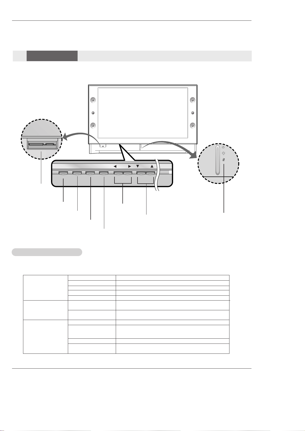
POWER TV GUIDE
VOL CH
ENTER
MENU
POWER Button
VOLUME (
F,G)
Buttons
CHANNEL (E, D) Buttons
Operation Indicator/
Lamp Indicator/
Temperature Indicator
ENTER Button
TV GUIDE Button
Off Power Cord is not connected.
Red Power Cord is connected, TV is in standby mode.
Green TV turns on.
Red (flashing) Power Cord is connected, TV is in booting sequence.
Orange (flashing) Preparing operation in standby mode.
Orange Projection lamp is reaching the end of its life and needs to
be replaced with a new lamp. Contact your service center.
Red (flashing) There is a problem with the lamp or around it. Contact an
authorized service center.
Green (flashing) The lamp cover is not closed.
Orange The projection TV is overheating. Check the blocked vents
of the Projection TV and the accumulated dust in the dust
filter.
Red The projection TV shuts down due to overheating.
Red (flashing) The projection TV shuts down, check the cooling fan.
Contact your service center.
Operation Indicator
Lamp Indicator
Temperature Indicator
- Lamp indicator, operation indicator, and temperature indicator located below the front panel controls, reveal the
operating status of the DLP projection TV.
Function Status Indicators
Function Status Indicators
Memory Card
Slots
MENU Button
Controls
Controls
Front Panel Controls
Front Panel Controls
Owner’s Manual
Introduction
PC/DTV
(XGA/
480p/
720p
1080i)
DVI
RGB/DVI
UPGRADE PORT
/
P
R
P
B
Y
DTV/DVD
RGB
PC/DTV
(XGA/
480p/
720p
1080i)
PC/DTV
(XGA
/480p
/720p
/1080i)
S-VIDEO
PR
PB
Y
MONO
CABLE
RGB INPUT
COMPONENT
INPUT2 INPUT1
DTV/DVD INPUT
RGB/DVI INPUT
(L)
(R)
AUDIO
(L)
(R)
AUDIO
VIDEO
(L)
(R)
AUDIO
(L)
(R)
AUDIO
AUDIO
CENTER
MODE IN
MONITOR
OUTPUT
VIDEO
INPUT2
VIDEO
INPUT1
DIGITAL AUDIO
OPTICAL INPUT1
(COMPONENT2)
DIGITAL AUDIO
OPTICAL INPUT2
(DVI)
IEEE1394
DIGITAL AUDIO
OPTICAL OUTPUT
ANTENNA
C
A
B
L
E
C
A
R
D
HDMI1/DVI
VARIABLE
AUDIO OUT
G-LINK
HDMI2
UPGRADE
PORT
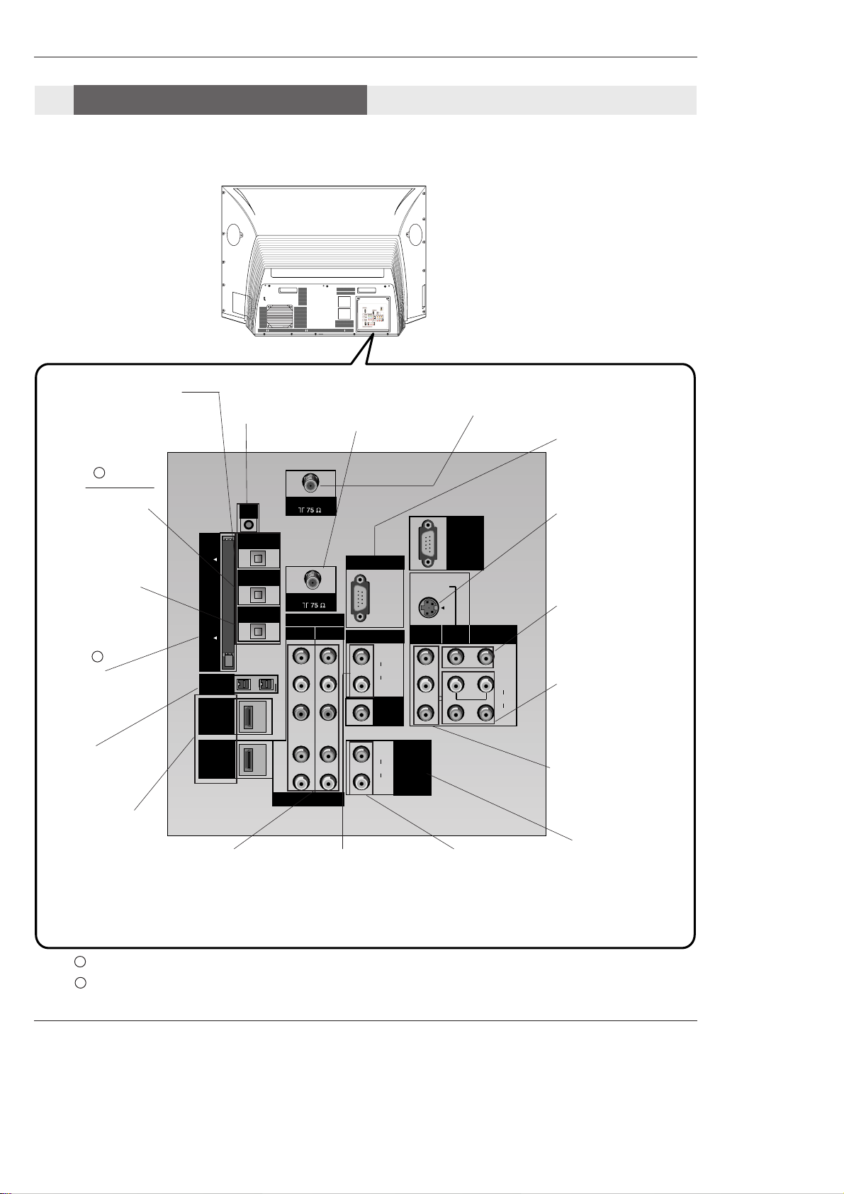
ANTENNA Inputs
Connect antenna signals to the TV directly.
DIGITAL AUDIO OPTICAL
OUTPUT
Used to connect either an external amplifier, or add a subwoofer to your surround sound
system if it has a digital
audio optical input.
(Refer to )
MONITOR OUTPUT
Connect a second TV or
Monitor.
S-VIDEO In
A connection available
with some high-end
equipment that provides
even better picture quality for Video 2.
RGB/DVI INPUT
Connect the monitor
output connector from
a PC to the appropriate input port.
RGB Input
Connect the TV output
connector from a PC/DTV
to the appropriate input
port.
AUDIO CENTER
MODE IN
Connect to external
Dolby Digital Center
“preamp output.”
VARIABLE AUDIO OUT
Used to connect either
an external amplifier,
or add a sub-woofer to
your surround sound
system.
COMPONENT INPUT 1-2
Connect a component
video/audio device to
these jacks. Refer to your
DVD manual for further
information.
VIDEO 1 or 2
Connects the video signals from various types
of equipment.
Left/Right AUDIO
Used for stereo sound
from various types of
equipment.
IEEE1394
Connect DVHS or
MicroMV to IEEE1394
Connector.
CableCARD™
Used for CableCARD™
received Cable Service
Provider.
CABLE Inputs
Connect cable signals to
the TV, either directly or
through your cable box.
G-LINK
Connect a G-
LINK Cable to
this jack.
DIGITAL AUDIO OPTICAL INPUT1(COMPONENT2)
Connect digital audio
from the equipment
whose video is connected to COMPONENT 2.
DIGITAL AUDIO OPTICAL INPUT2(DVI)
Connect digital audio
from the equipment
whose video is connected to
HDMI/DVI(VIDEO).
(Refer to )
Notes: In standby mode, these port will not work.
If the video is connected through HDMI-TO-HDMI cable, you don’t need to connect digital audio. This port
is used only when the video connected through DVI-TO-HDMI cable.
1
2
1
2
HDMI1/DVI, HDMI 2
Connect a HDMI signal
to HDMI1/DVI or
HDMI2. Or connect a
DVI(Video) signal to
HDMI1/DVI.
Back Connection Panel
Back Connection Panel
Connection Options
Connection Options
DLP Projection TV
Introduction
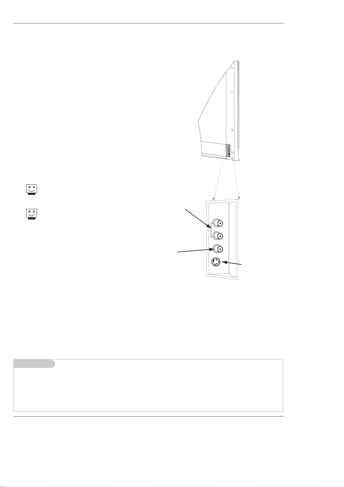
LEFT/RIGHT
AUDIO
Used for stereo
sound from various types of
equipment.
S-VIDEO
A connection
available on some
very high-end
equipment that
provides better
picture quality
than video input.
VIDEO
Connects the
video signals
from any piece of
equipment.
Front A/V Panel
S-VIDEO
VIDEO
FRONT A/V
AUDIO
(R)
(L)/
MONO
There are four jacks on the left side on your projection TV
that make connecting Audio/Video devices like video games
and camcorders very simple.
The jacks are like those found on the back jack connection
panel. This means that most equipment that connects to
those types of jacks on the rear jackpack, may be connected to the front connection panel.
To use the side jacks as the signal source, select them
using Main Input menu as described on page 58. They will
be named “Front Video” in the Main Input menu.
If you input both Front Video and
S-Video, only the S-Video will
work.
If you’re connecting a video game
device, make sure to change the
picture settings with the EZ
Picture option in the Video menu
(see page 59).
Mini glossary
A/V CABLESAudio/Video cables. Three cable connector—Right audio (red), Left audio (white), and Video (yellow). A/V cables are
used for stereo playback of videocassettes and for higher quality picture and sound from other A/V devices.
A/V DEVICE Any device that produces video or sound (VCR, DVD, cable box, or television).
Front Connection Panel
Front Connection Panel
Owner’s Manual
 Loading...