

LG DSH6 Owner’s Manual
OWNER’S MANUAL
Wireless
Sound Bar
Please read this manual carefully before operating your set and retain it for future reference.
MODEL
DSH6 (DSH6, SPH5-W)
*MFL70179902* |
www.lg.com |
Copyright © 2017 LG Electronics. All Rights Reserved |
Getting Started |
3 |
|
|
Safety Information
CAUTION
RISK OF ELECTRIC SHOCK
DO NOT OPEN
CAUTION: TO REDUCE THE RISK OF ELECTRIC SHOCK DO NOT REMOVE COVER (OR BACK) NO USER-SERVICEABLE PARTS INSIDE REFER SERVICING TO QUALIFIED SERVICE PERSONNEL.
This lightning flash with arrowhead symbol within an equilateral triangle is intended to alert the user to the presence of uninsulated dangerous voltage within the
product’s enclosure that may be of sufficient magnitude to constitute a risk of electric shock to persons.
The exclamation point within an equilateral triangle is intended to alert the user to the presence of important operating and maintenance (servicing) instructions in the literature accompanying the product.
WARNING: TO PREVENT FIRE OR ELECTRIC SHOCK HAZARD, DO NOT EXPOSE THIS PRODUCT TO RAIN OR MOISTURE.
CAUTION: The apparatus should not be exposed to water (dripping or splashing) and no objects filled with liquids, such as vases, should be placed on the apparatus.
WARNING: Do not install this equipment in a confined space such as a book case or similar unit.
CAUTION: Do not use high voltage products around this product. (ex. Electrical swatter)This product may malfunction due to electrical shock.
CAUTION: No naked flame sources, such as lighted candles, should be placed on the apparatus.
CAUTION: Do not block any ventilation openings. Install in accordance with the manufacturer’s instructions.
Slots and openings in the cabinet are provided for ventilation and to ensure reliable operation of the product and to protect it from over heating. The openings shall be never be blocked by placing the product on a bed, sofa, rug or other similar surface.This product shall not be placed in a builtin installation such as a bookcase or rack unless
proper ventilation is provided or the manufacturer’s instruction has been adhered to.
CAUTION concerning the Power Cord
The Power Plug is the disconnecting device.In case of an emergency, the Power Plug must remain readily accessible. Check the specification page of this owner’s manual to be certain of the current requirements. Do not overload wall outlets. Overloaded wall outlets, loose or damaged wall outlets, extension cords, frayed power cords, or damaged or cracked wire insulation are dangerous. Any of these conditions could result in electric shock or fire. Periodically examine the cord of your device, and if its appearance indicates damage
or deterioration, unplug it, discontinue use of the device, and have the cord replaced with an exact replacement part by an authorized service center.
Protect the power cord from physical or mechanical abuse, such as being twisted, kinked, pinched, closed in a door, or walked upon. Pay particular attention to plugs, wall outlets, and the point where the cord exits the device.
NOTICE: For safety marking information including product identification and supply ratings, please refer to the main label on the bottom or the other surface of the product.
1
<![if ! IE]><![endif]>Started Getting

1
<![if ! IE]><![endif]>Started Getting
4 Getting Started |
|
||
|
|
|
|
This device is equipped with a portable battery or |
Symbols |
||
accumulator. |
|||
|
|||
Safety way to remove the battery from the equipment: Remove the old battery or battery pack, follow the steps in reverse order than the assembly. To prevent contamination of the environment and bring on possible threat to human and animal health, the old battery or the battery put it in the appropriate container at designated collection points. Do not dispose of batteries or battery together with other waste.It is recommended that you use local, free reimbursement systems batteries and accumulators. The battery should not be exposed to excessive heat such as sunshine, fire or the like.
For models using an adapter
Only use the AC adapter supplied with this device. Do not use a power supply from another device or another manufacturer. Using any other power cable or power supply may cause damage to the device and void your warranty.
~Refers to alternating current(AC).
0 |
Refers to direct current(DC). |
|
|
|
Refers to class II equipment. |
|
|
1 |
Refers to stand-by. |
|
|
!Refers to “ON” (power).
Refers to dangerous voltage.

Table of Contents |
5 |
|
|
Table of Contents
1 |
Getting Started |
3 |
Operating |
||
|
|
|
|
|
|
3 |
Safety Information |
21 |
Basic operations |
||
6 |
Unique features |
21 |
– USB operation |
||
6 |
Introduction |
22 |
Other operations |
||
6 |
– Symbols used in this manual |
22 |
– AV Sync |
||
6 |
Accessories |
22 |
– Auto Display /Auto Dimmer |
||
7 |
Remote control |
22 |
– Using your TV remote control |
||
8 |
Front panel |
23 |
– AUTO POWER On/Off |
||
8 |
Rear panel |
24 |
– Auto function change |
||
9 |
Installing the sound bar |
24 |
– LG Sound Sync |
||
10 |
Mounting the main unit on a wall |
26 |
Using BLUETOOTH® technology |
||
|
|
26 |
– Listening to music stored on the |
||
2 |
Connecting |
|
|
BLUETOOTH devices |
|
28 |
Using BLUETOOTH App |
||||
12 |
Connecting the AC Adapter |
28 |
– Install “Music Flow Bluetooth” App onto |
||
12 |
Wireless subwoofer connection |
|
|
Your BLUETOOTH Device |
|
14 |
Connecting to your TV |
28 |
– Activate Bluetooth with “Music Flow |
||
14 |
– Using an OPTICAL cable |
|
|
Bluetooth” App |
|
14 |
– Using an HDMI cable |
29 |
Sound adjustment |
||
15 |
– Enjoy the Rich sound of Live TV broadcasts |
29 |
– Setting sound effect |
||
|
through the sound bar |
30 |
– Adjust volume level automatically |
||
15 |
– What is SIMPLINK? |
30 |
– Adjust the Subwoofer/Treble/Bass |
||
16 |
– ARC (Audio Return Channel) function |
30 |
– Night mode |
||
16 |
– Additional information for HDMI |
|
|
|
|
17 |
Optional equipment connection |
4 |
Troubleshooting |
||
17 |
– HDMI connection |
||||
|
|
|
|||
31 |
Troubleshooting |
||||
18 |
– OPTICAL IN connection |
||||
18 |
– PORTABLE IN connection |
32 |
NOTES to use wireless |
||
19 |
– USB connection |
|
|
|
|
19 |
– Compatible USB devices |
5 |
Appendix |
||
19 |
– USB device requirement |
||||
|
|
|
|||
20 |
– Playable file |
33 |
Trademarks and licenses |
||
|
|
34 |
Specifications |
||
|
|
36 |
Maintenance |
||
|
|
36 |
– Handling the unit |
||
1
2
3
4
5

1
<![if ! IE]><![endif]>Started Getting
6 Getting Started
Unique features
Auto power down
This unit will turn off by itself for energy saving consumption.
Portable In
Listens to music from your portable device. (MP3, Notebook, etc)
Accessories
Please check and identify the supplied accessories.
Designs and specifications of the accessories are subject to change without prior notice.
Remote control (1) |
Batteries (2) |
LG Sound Sync
Controls volume level of this unit by the remote control of your LGTV that is compatible with LG Sound Sync.
|
AC adapter (1) |
Power cords (2) |
Introduction |
|
|
Symbols used in this manual |
|
|
,,Note |
Wall brackets (2) |
Wall bracket install |
Indicates special notes and operating features. |
|
guide (1) |
|
|
>>Caution
Indicates cautions for preventing possible damages from abuse.
Screws (2)

Getting Started |
7 |
|
|
Remote control |
• • • • • • • • • • • • • •A• |
|
|
|
1(Power) : Switches the unit ON or OFF. / Switches |
|
to the standby mode. |
|
F : Selects the function and the input source. |
|
SOUND EFFECT : Selects a sound effect mode. |
|
VOL o/p: Adjusts speaker volume. |
|
(Night mode) : Turns on or off Night mode. |
|
(Mute) : Mutes the sound. |
|
: Adjusts sound level ofTreble, Bass and Sub- |
|
woofer. |
|
• • • • • • • • • • • • • •B• |
|
C/V(Skip/Search) : |
|
- Skips Fast backward or Forward. |
|
- Searches for a section within a file. |
|
dM(Play/Pause) : Starts playback. / Pauses playback. |
|
FOLDER o/p: Searches a folder on USB device. |
|
REPEAT : Listen to your files repeatedly or randomly. |
|
AUTO VOL : Turns on and off the AUTO VOLUME |
Replacement of Battery |
mode. |
AV SYNC : |
|
|
- Synchronizes the audio and video. |
|
- Controls this unit usingTV remote.(Refer to the |
|
page 22.) |
|
AUTO POWER : |
Remove the battery cover on the rear of the remote control, and insert battery with
with and matched correctly.
-Turns on or off AUTO POWER function. (Refer to the page 23.)
-Turns on or off Auto Display Off function (Refer to the page 22.)
1
<![if ! IE]><![endif]>Started Getting

8 Getting Started
Front panel
1
<![if ! IE]><![endif]>Started Getting
ARemote sensor |
CThe buttons are located on the rear. |
BDisplay window |
|
Rear panel
Ao/p: (Volume) : Adjusts volume level
F (Function) : Selects the function and input source.
1/!(Standby/On)
BDC IN : AC adapter input COPTICAL IN : Optical input
DPORTABLE IN : Portable input EUSB Port
FHDMI IN / OUT (TV ARC) : HDMI input / output
Installing the sound bar
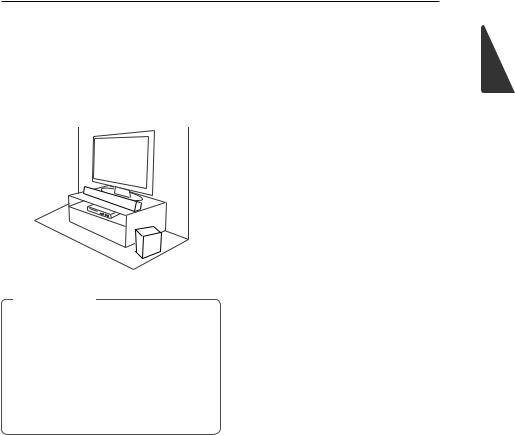
You can hear the sound by connecting the unit to the other device :TV, Blu-ray disc player, DVD player, etc.
Place the unit in front of theTV and connect it to the device you want. (Refer to pages 14 - 20.)
>>Caution
yy For best performance of wireless connection such as Bluetooth or wireless subwoofer, do not install the unit on Metallic furniture because wireless connection communicates through a module positioned on the bottom of the unit.
yy Be careful not to make scratches on the surface of the Unit /Sub-Woofer when installing or moving them.
Getting Started |
9 |
1
<![if ! IE]><![endif]>Started Getting

1
<![if ! IE]><![endif]>Started Getting
10 Getting Started
Mounting the main unit |
1. |
install guide with the bottom of TV and attach to |
|
Match theTV’s BOTTOM EDGE of Wall bracket |
on a wall |
the position. |
|
|
You can mount the main unit on a wall. |
|
|
|
|
|
|
|
|
|
|
2. When you mount it on a wall (concrete), use the |
||
|
>>Caution |
|
wall plugs. You should drill some holes. A guide |
||
|
|
sheet (Wall bracket install guide) is supplied to |
|||
|
Because it is difficult |
to make a connection after |
drill. Use the sheet to check the point to drill. |
||
installing this unit, you should connect the cables |
|
|
|
||
before installation. |
|
|
|
||
Preparation materials
Unit
 Wall bracket install guide

 Wall brackets
  3. Remove the Wall bracket install guide.
Screws (Not supplied)
Screws (A)


 Wall plug
Getting Started 11
4. Fix the brackets with screws (A) as shown in the |
6. Fix the unit with the screws firmly. |
illustration below. |
|
,,Note
Screws (A) and Wall Plugs are not supplied for mounting the unit. We recommend the Hilti (HUD-1 6 x 30) for the mounting.
5.Put the unit on the brackets to match screw holes on the bottom of the unit.
1
<![if ! IE]><![endif]>Started Getting
,,Note
To detach the unit, perform it in reverse order.
>>Caution
yy Do not install this unit upside down.It can damage the parts of this unit or be the cause of personal injury.
yy Do not hang onto the installed unit and avoid any impact to the unit.
yy Secure the unit firmly to the wall so that it does not fall off.If the unit falls off, it may result in an injury or damage to the product.
yy When the unit is installed on a wall, please make sure that a child does not pull any of connecting cables, as it may cause it to fall.

2
<![if ! IE]><![endif]>Connecting
12 Connecting
Connecting the AC
Adapter
Connect the speaker to the power supply with the supplied AC adapter.
1.Connect the supplied AC power cord to the AC adapter.
2.Connect the AC adapter cable to DCIN adapter input.
3.Plug the AC power cord into an AC outlet.
Wireless subwoofer connection
LED indicator of wireless subwoofer
LED Color |
Status |
Green |
Attempting to make connection. |
(Blink) |
|
Green |
The connection is completed. |
Red |
The wireless subwoofer is in |
|
standby mode or the connection |
|
is failed. |
Red/Green |
The wireless subwoofer |
(Blink |
connection is initialized. |
alternately) |
|
Off |
The power cord of wireless |
(No display) |
subwoofer is disconnected. |
Setting up the wireless subwoofer for the first time
1.Connect the power cord to the subwoofer and plug the power cord into a power outlet.
2.Turn on the main unit :The sound bar and wireless subwoofer will be automatically connected.
-- Green LED on the rear of wireless subwoofer turns on.
 Loading...