

Page 1
MODEL : DP471B/DP472B/DP473BSERVICE MANUAL
Internal Use Only
Website http://biz.lgservice.com
PORTABLE DVD
SERVICE MANUAL
MODEL : DP471B/DP472B/DP473B
P/NO : AFN73065036 APRIL, 2009
CAUTION
BEFORE SERVICING THE UNIT, READ THE “SAFETY PRECAUTIONS”
IN THIS MANUAL.
Page 2

CONTENTS
SECTION 1.........SUMMARY
SECTION 2.........EXPLODED VIEWS
SECTION 3.........ELECTRICAL
SECTION 4.........REPLACEMENT PARTS LIST
Copyright © 2009 LG Electronics. Inc. All right reserved.
Only for training and service purposes
1-1
LGE Internal Use Only
Page 3

SECTION 1
SUMMARY
CONTENTS
PRODUCT SAFETY SERVICING GUIDELINES FOR VIDEO PRODUCTS .............................................. 1-3
SERVICING PRECAUTIONS .......................................................................................................................... 1-4
• GENERAL SERVICING PRECAUTIONS
• INSULATION CHECKING PRODEDURE
• ELECTROSTATICALLY SENSITIVE (ES) DEVICES
SPECIFICATIONS ............................................................................................................................................ 1-5
LGE Internal Use Only
1-2
Copyright © 2009 LG Electronics. Inc. All right reserved.
Only for training and service purposes
Page 4
PRODUCT SAFETY SERVICING GUIDELINES FOR VIDEO PRODUCTS
IMPORTANT SAFETY NOTICE
This manual was prepared for use only by properly trained audio-video service
technicians.
When servicing this product, under no circumstances should the original design be
modified or altered without permission from LG Corporation. All components should
be replaced only with types identical to those in the original circuit and their physical
location, wiring and lead dress must conform to original layout upon completion of
repairs.
Special components are also used to prevent x-radiation, shock and fire hazard.
These components are indicated by the letter “x” included in their component designators and are required to maintain safe performance. No deviations are allowed
without prior approval by LG Corporation.
Circuit diagrams may occasionally differ from the actual circuit used. This way,
implementation of the latest safety and performance improvement changes into the
set are not delayed until the new service literature is printed.
CAUTION: Do not attempt to modify this product in any way. Never perform cus-
tomized installations without manufacturer’s approval. Unauthorized modifications
will not only void the warranty, but may lead to property damage or user injury.
Service work should be performed only after you are thoroughly familiar with these
safety checks and servicing guidelines.
GRAPHIC SYMBOLS
The exclamation point within an equilateral triangle is intended to
alert the service personnel to important safety information in the
service literature.
The lightning flash with arrowhead symbol within an equilateral
triangle is intended to alert the service personnel to the presence of
noninsulated “dangerous voltage” that may be of sufficient magnitude
to constitute a risk of electric shock.
The pictorial representation of a fuse and its rating within an equilateral triangle is intended to convey to the service personnel the
following fuse replacement caution notice:
CAUTION: FOR CONTINUED PROTECTION AGAINST RISK
OF FIRE, REPLACE ALL FUSES WITH THE SAME TYPE AND
RATING AS MARKED NEAR EACH FUSE.
SERVICE INFORMATION
While servicing, use an isolation transformer for protection from AC line shock. After
the original service problem has been corrected, make a check of the following:
FIRE AND SHOCK HAZARD
1. Be sure that all components are positioned to avoid a possibility of adjacent
component shorts. This is especially important on items trans-ported to and from
the repair shop.
2. Verify that all protective devices such as insulators, barriers, covers, shields,
strain reliefs, power supply cords, and other hardware have been reinstalled per
the original design. Be sure that the safety purpose of the polarized line plug has
not been defeated.
3. Soldering must be inspected to discover possible cold solder joints, solder
splashes, or sharp solder points. Be certain to remove all loose foreign particles.
4. Check for physical evidence of damage or deterioration to parts and components, for frayed leads or damaged insulation (including the AC cord), and
replace if necessary.
5. No lead or component should touch a high current device or a resistor rated at 1
watt or more. Lead tension around protruding metal surfaces must be avoided.
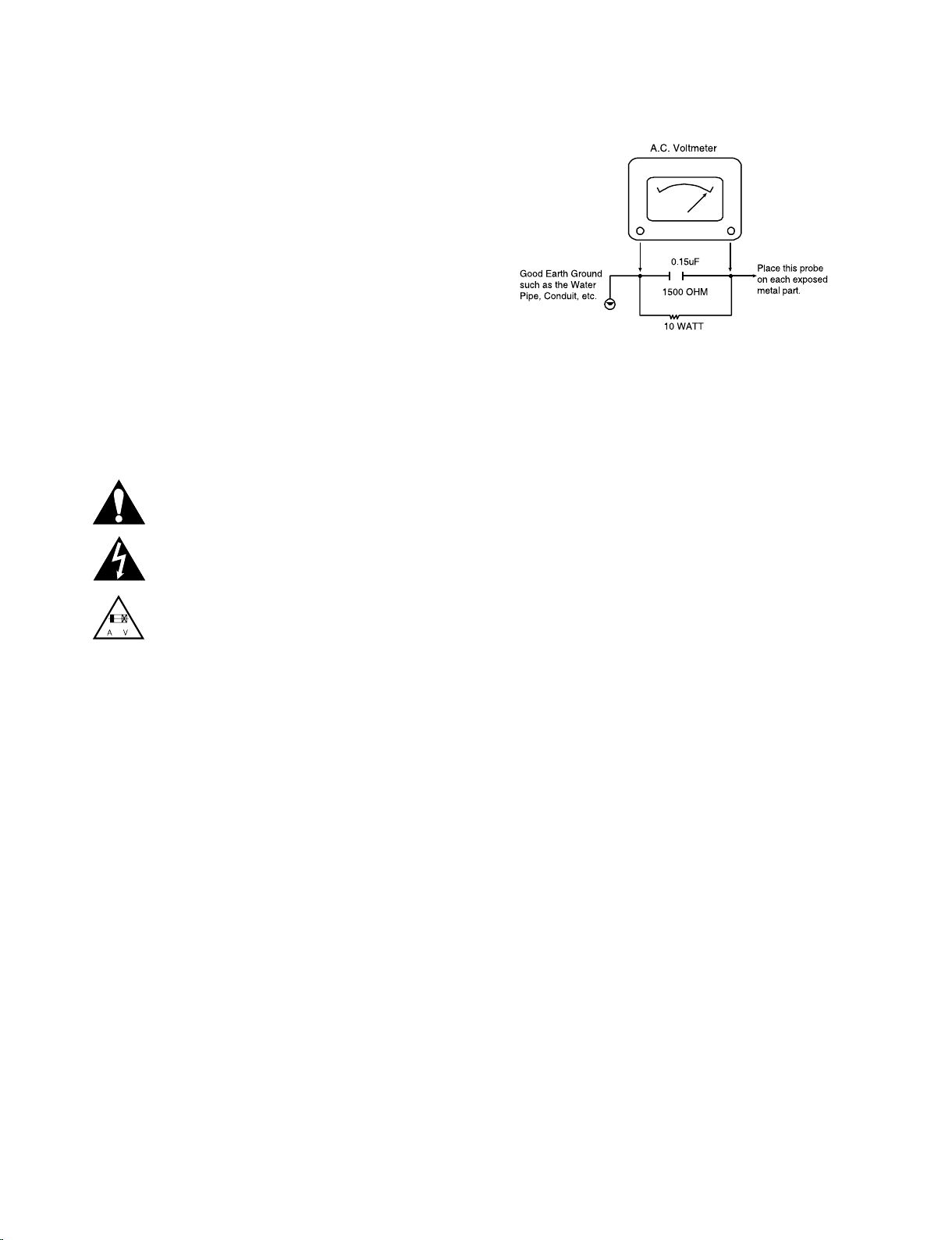
6. After reassembly of the set, always perform an AC leakage test on all exposed
metallic parts of the cabinet (the channel selector knobs, antenna terminals,
handle and screws) to be sure that set is safe to operate without danger of
electrical shock. DO NOT USE A LINE ISOLATION TRANSFORMER DURING
THIS TEST. Use an AC voltmeter having 5000 ohms per volt or more sensitivity
in the following manner: Connect a 1500 ohm, 10 watt resistor, paralleled by a
.15 mfd 150V AC type capacitor between a known good earth ground water pipe,
conduit, etc.) and the exposed metallic parts, one at a time. Measure the AC voltage across the combination of 1500 ohm resistor and .15 mfd capacitor. Reverse
the AC plug by using a non-polarized adaptor and repeat AC voltage measurements for each exposed metallic part. Voltage measured must not exceed 0.75
volts RMS. This corresponds to 0.5 milliamp AC. Any value exceeding this limit
constitutes a potential shock hazard and must be corrected immediately.
TIPS ON PROPER INSTALLATION
1. Never install any receiver in a closed-in recess, cubbyhole, or closely fitting shelf
space over, or close to, a heat duct, or in the path of heated air flow.
2. Avoid conditions of high humidity such as: outdoor patio installations where dew
is a factor, near steam radiators where steam leakage is a factor, etc.
3. Avoid placement where draperies may obstruct venting. The customer should
also avoid the use of decorative scarves or other coverings that might obstruct
ventilation.
4. Wall- and shelf-mounted installations using a commercial mounting kit must
follow the factory-approved mounting instructions. A product mounted to a shelf
or platform must retain its original feet (or the equivalent thickness in spacers) to
provide adequate air flow across the bottom. Bolts or screws used for fasteners
must not touch any parts or wiring. Perform leakage tests on customized installations.
5. Caution customers against mounting a product on a sloping shelf or in a tilted
position, unless the receiver is properly secured.
6. A product on a roll-about cart should be stable in its mounting to the cart.
Caution the customer on the hazards of trying to roll a cart with small casters
across thresholds or deep pile carpets.
7. Caution customers against using extension cords. Explain that a forest of extensions, sprouting from a single outlet, can lead to disastrous consequences to
home and family.
Copyright © 2009 LG Electronics. Inc. All right reserved.
Only for training and service purposes
1-3
LGE Internal Use Only
Page 5

SERVICING PRECAUTIONS
CAUTION: Before servicing the PORTABLE DVD covered by
this service data and its supplements and addends, read and
follow the SAFETY PRECAUTIONS. NOTE: if unforeseen
circumstances create conflict between the following servicing
precautions and any of the safety precautions in this publication, always follow the safety precautions.
Remember Safety First :
General Servicing Precautions
1. Always unplug the PORTABLE DVD AC power cord from
the AC power source before:
(1) Removing or reinstalling any component, circuit board,
module, or any other assembly.
(2) Disconnecting or reconnecting any internal electrical
plug or other electrical connection.
(3) Connecting a test substitute in parallel with an electro-
lytic capacitor.
Caution: A wrong part substitution or incorrect polarity
installation of electrolytic capacitors may result in an
explosion hazard.
2. Do not spray chemicals on or near this PORTABLE DVD or
any of its assemblies.
3. Unless specified otherwise in this service data, clean electrical contacts by applying an appropriate contact cleaning
solution to the contacts with a pipe cleaner, cotton-tipped
swab, or comparable soft applicator.
Unless specified otherwise in this service data, lubrication
of contacts is not required.
4. Do not defeat any plug/socket B+ voltage interlocks with
which instruments covered by this service manual might be
equipped.
5. Do not apply AC power to this PORTABLE DVD and / or
any of its electrical assemblies unless all solid state device
heat sinks are correctly installed.
6. Always connect the test instrument ground lead to an
appropriate ground before connecting the test instrument
positive lead. Always remove the test instrument ground
lead last.
Insulation Checking Procedure
Disconnect the attachment plug from the AC outlet and
turn the power on. Connect an insulation resistance meter
(500V)
to the blades of the attachment plug. The insulation resistance
between each blade of the attachment plug and accessible
conductive parts (Note 1) should be more than 1Mohm.
Note 1: Accessible Conductive Parts include Metal panels,
Input terminals, Earphone jacks,etc.
Electrostatically Sensitive (ES) Devices
Some semiconductor (solid state) devices can be damaged
easily by static electricity. Such components commonly are
called Electrostatically Sensitive (ES) Devices. Examples
of typical ES devices are integrated circuits and some field
effect transistors and semiconductor chip components.
The following techniques should be used to help reduce the
incidence of component damage caused by static electricity.
1. Immediately before handling any semiconductor component or semiconductor-equipped assembly, drain off any
electrostatic charge on your body by touching a known
earth ground. Alternatively, obtain and wear a commercially available discharging wrist strap device, which should
be removed for potential shock reasons prior to applying
power to the unit under test.
2. After removing an electrical assembly equipped with ES
devices, place the assembly on a conductive surface such
as aluminum foil, to prevent electrostatic charge buildup or
exposure of the assembly.
3. Use only a grounded-tip soldering iron to solder or unsolder
ES devices.
4. Use only an anti-static solder removal device. Some solder
removal devices not classified as “anti-static” can generate
electrical charges sufficient to damage ES devices.
5. Do not use freon-propelled chemicals. These can generate
an electrical charge sufficient to damage ES devices.
6. Do not remove a replacement ES device from its protective
package until immediately before you are ready to install
it. (Most replacement ES devices are packaged with leads
electrically shorted together by conductive foam, aluminum
foil, or comparable conductive material).
7. Immediately before removing the protective material from
the leads of a replacement ES device, touch the protective
material to the chassis or circuit assembly into which the
device will be installed.
Caution: Be sure no power is applied to the chassis or
circuit, and observe all other safety precautions.
8. Minimize bodily motions when handling unpackaged
replacement ES devices. (Normally harmless motion such
as the brushing together of your clothes fabric or the lifting
of your foot from a carpeted floor can generate static electricity sufficient to damage an ES device.)
LGE Internal Use Only
1-4
Copyright © 2009 LG Electronics. Inc. All right reserved.
Only for training and service purposes
Page 6

SPECIFICATIONS
• DVD PLAYER
Power requirements DC 9 ~ 15V
Power consumption 13W
External dimensions 202 x 44 x 165mm (W x H x D)
Net weight (Approx.) 0.82kg
Operating temperature 0°C to 45°C
Operating humidity 0% to 60%
Laser semiconductor laser
Signal system PAL/NTSC
• CONNECTORS
Audio/Video Output ø3.5mm mini jack x 1
- Video: 1.0V(p-p), 75Ω, sync negative
- Audio: 2Vrms (1kHz, 0dB)
Earphone terminal ø3.5mm stereo mini jack x 2
USB 2.0 Type:A
• LIQUID CRYSTAL DISPLAY
Panel size 7inches wide (diagonal)
Projection system R.G.B. stripe
Driving system TFT active matrix
Resolution 480 x 234 (WQVGA)
• SUPPLIED ACCESSORIES
RCA Video/Audio cable
AC Adapter (MPA-630)
Automotive Adapter (Cu-2993)
Remote Control
Battery for Remote Control (Lithium Battery)
Copyright © 2009 LG Electronics. Inc. All right reserved.
Only for training and service purposes
1-5
LGE Internal Use Only
Page 7

MEMO
LGE Internal Use Only
1-6
Copyright © 2009 LG Electronics. Inc. All right reserved.
Only for training and service purposes
Page 8

SECTION 2
EXPLODED VIEWS
CONTENTS
EXPLODED VIEWS ......................................................................................................................................... 2-2
1. CABINET AND MAIN FRAME SECTION ................................................................................................. 2-2
2. PACKING ACCESSORY SECTION ......................................................................................................... 2-3
Copyright © 2009 LG Electronics. Inc. All right reserved.
Only for training and service purposes
2-1
LGE Internal Use Only
Page 9

A
LCD
BOARD
LCD
PANEL
MAIN
BOARD
C
A
B
E
D
B
C
ED
475
279
278
277
476
277
477
477
477
477
474
474
271
477
251
272
A48
A40
262
264
475
263
260
262
262
809
265
282
289
284
287
283
283
288
288
290
286
285
478
280
281
280
475
475
475
A44
A00
A53
A46
A43
A52
A51
CABLE3
SVC purchase order caution
Cables must be ordered assembly part.
Supply is possible in Location No. 278,
A40 and A53.
EXPLODED VIEWS
1. CABINET AND MAIN FRAME SECTION
LGE Internal Use Only
2-2
Copyright © 2009 LG Electronics. Inc. All right reserved.
Only for training and service purposes
Page 10
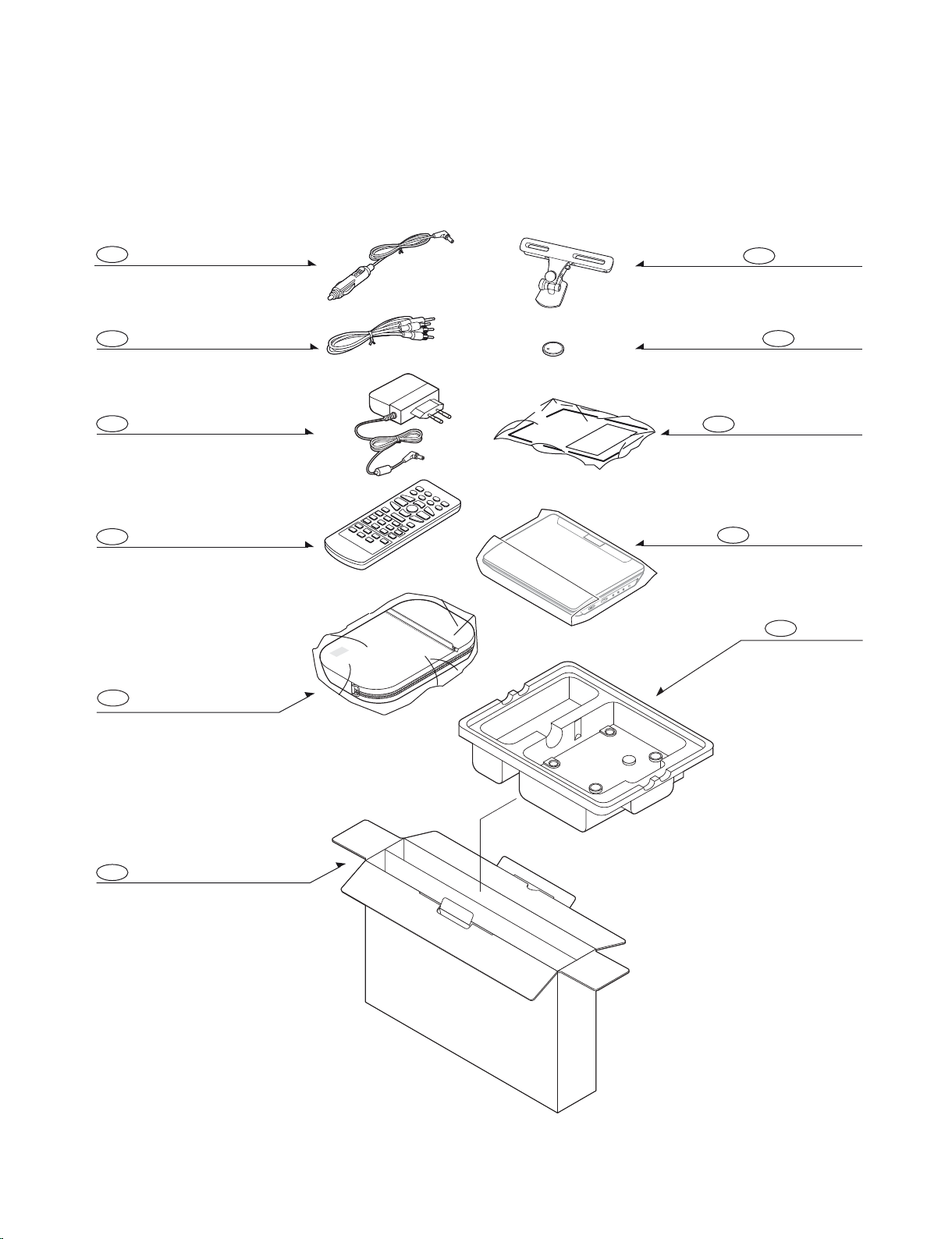
2. PACKING ACCESSORY SECTION
803
PACKING
839
PLUG ASS'Y(RCA CABLE)
806
834
ADAPTER
833
REMOTE CONTROL
900
CARRING CASE
BOX
802
801
OWNER'S MANUAL
CABLE, CIGAR JACK
804
PACKING SHEET
835
CAR-MOUNT
808
BATTERY
Copyright © 2009 LG Electronics. Inc. All right reserved.
Only for training and service purposes
2-3
LGE Internal Use Only
Page 11

MEMO
LGE Internal Use Only
2-4
Copyright © 2009 LG Electronics. Inc. All right reserved.
Only for training and service purposes
Page 12

SECTION 3
ELECTRICAL
CONTENTS
ELECTRICAL TROUBLESHOOTING GUIDE ................................................................................... 3-2
1. POWER CHECK FLOW ........................................................................................................................3-2
2. SYSTEM OPERATION FLOW ...............................................................................................................3-3
3. SYSTEM TEST FLOW ...........................................................................................................................3-4
DETAILS AND WAVEFORMS ON SYSTEM TEST AND DEBUGGING ................................ 3-11
1. SYSTEM 27MHZ CLOCK, RESET, FLASH SCK SIGNAL. ..................................................................3-9
2. SDRAM CLOCK ...................................................................................................................................3-11
3. TRAY OPEN/CLOSE SIGNAL .............................................................................................................3-11
4. SLED CONTROL RELATED SIGNAL .................................................................................................3-12
5. LASER POWER CONTROL RELATED SIGNAL ................................................................................ 3-13
6. SPINDLE CONTROL WAVEFORM .....................................................................................................3-13
7. FOCUS ON WAVEFORM ....................................................................................................................3-14
8. TRACKING CONTROL RELATED SIGNAL(SYSTEM CHECKING) ................................................... 3-15
9. VIDEO OUTPUT WAVEFORM ............................................................................................................3-16
10. AUDIO OUTPUT ..................................................................................................................................3-16
WIRING CONNECTION DIAGRAM ....................................................................................................3-17
BLOCK DIAGRAMS ................................................................................................................................3-18
1. OVERALL BLOCK DIAGRAM .............................................................................................................3-18
2. SYSTEM BLOCK DIAGRAM ...............................................................................................................3-19
3. DC BLOCK DIAGRAM .........................................................................................................................3-20
CIRCUIT DIAGRAMS ..............................................................................................................................3-27
1. LCD I/F CIRCUIT DIAGRAM ...............................................................................................................3-21
2. OPU CIRCUIT DIAGRAM ....................................................................................................................3-23
3. HP/SPK AMP CIRCUIT DIAGRAM ......................................................................................................3-25
4. AUDIO I/F CIRCUIT DIAGRAM ...........................................................................................................3-27
5. MOTOR DRIVE CIRCUIT DIAGRAM ..................................................................................................3-29
6. MEMORY CIRCUIT DIAGRAM............................................................................................................3-31
7. MPEG CIRCUIT DIAGRAM ................................................................................................................. 3-33
8. VIDEO CONTROLER CIRCUIT DIAGRAM .........................................................................................3-35
9. AV I/F CIRCUIT DIAGRAM ..................................................................................................................3-37
10. USB I/F CIRCUIT DIAGRAM ...............................................................................................................3-39
11. LCD POWER CIRCUIT DIAGRAM ......................................................................................................3-41
12. MPEG POWER CIRCUIT DIAGRAM .................................................................................................. 3-43
13. INPUT POWER CIRCUIT DIAGRAM ..................................................................................................3-45
14. B/L POWER CIRCUIT DIAGRAM ........................................................................................................3-47
15. CHARGER POWER CIRCUIT DIAGRAM ........................................................................................... 3-49
16. SWITCH & VIDEO BUFFER CIRCUIT DIAGRAM ..............................................................................3-51
CIRCUIT VOLTAGE CHART ...........................................................................................................3-53
PRINTED CIRCUIT BOARD DIAGRAMS ......................................................................................... 3-57
1. MAIN P.C. BOARD ..............................................................................................................................3-57
2. LCD P.C. BOARD ................................................................................................................................ 3-57
Copyright © 2009 LG Electronics. Inc. All right reserved.
Only for training and service purposes
3-1
LGE Internal Use Only
Page 13
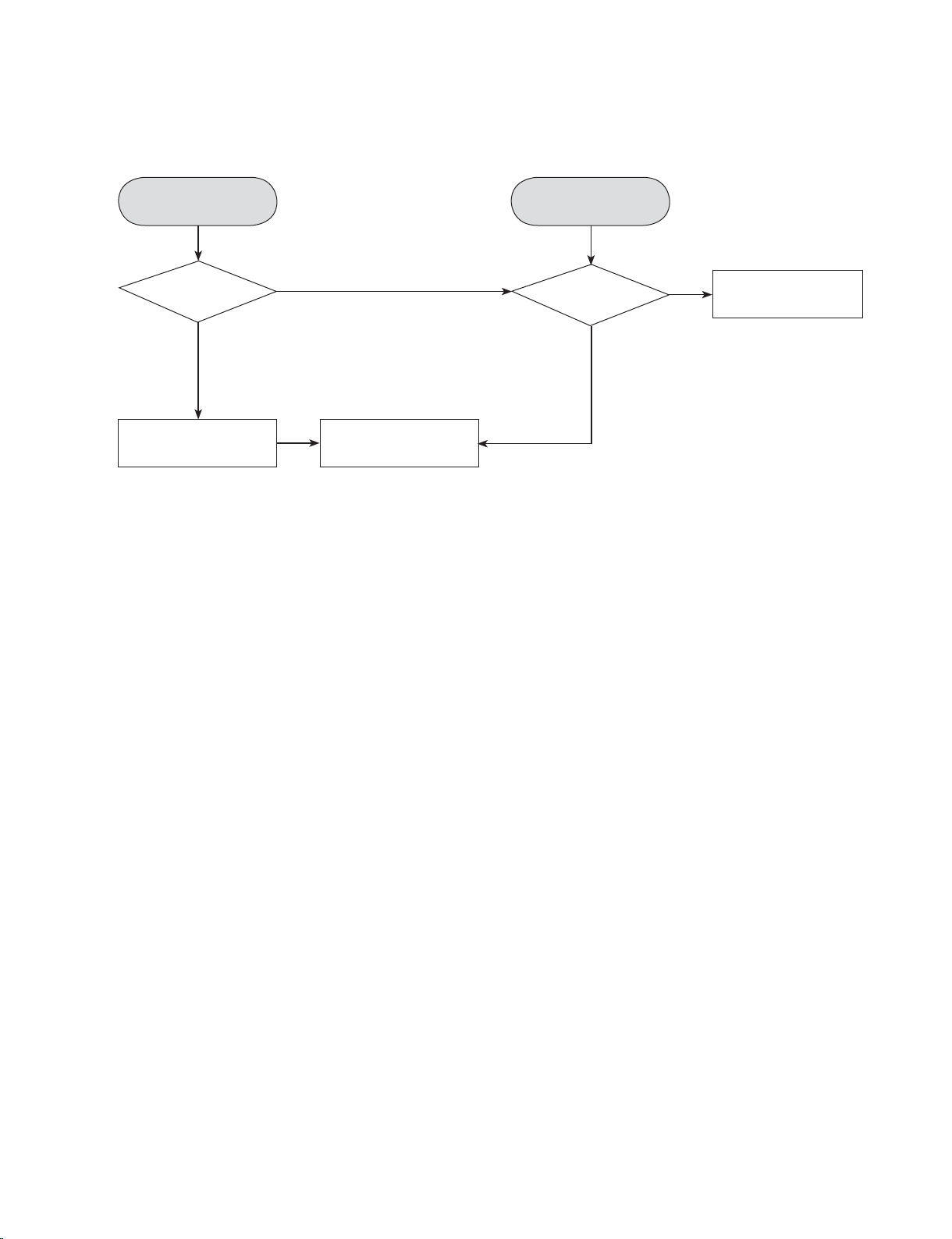
ELECTRICAL TROUBLESHOOTING GUIDE
1. POWER CHECK FLOW
A. B.
No 1.8V
No 5V or 3.3V
Is
3.3V section
working?
YES
Replace C19,C23
YES
NO
Replace U16
Check
VCC_ADP
YES
NO
Replace
D5, Q11, Q16, Q19
LGE Internal Use Only
3-2
Copyright © 2009 LG Electronics. Inc. All right reserved.
Only for training and service purposes
Page 14
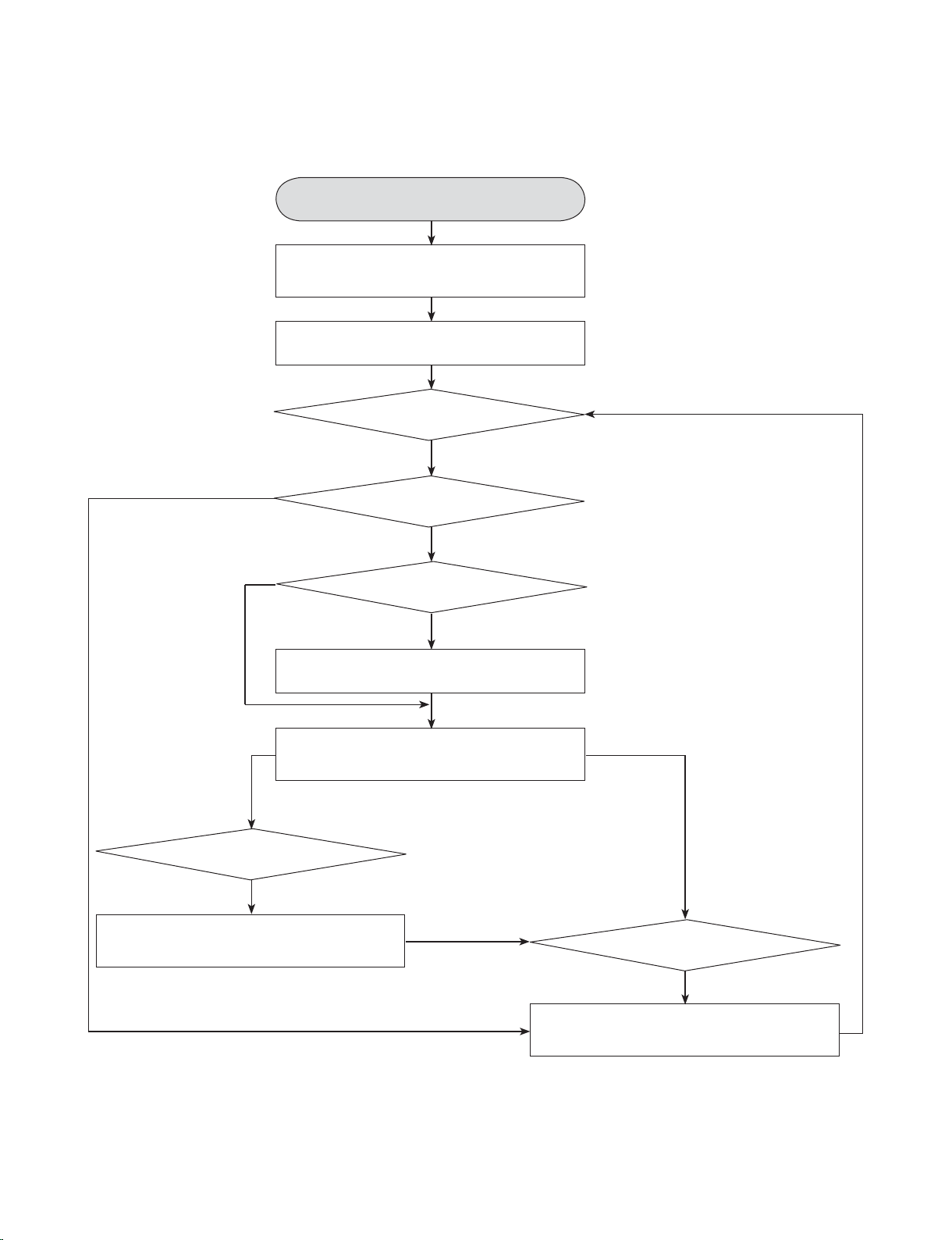
2. SYSTEM OPERATION FLOW
Power on
1. 8032 initializes SERVO,DSP & RISC registers
2. Write RISC code to SDRAM
3. Reset RISC
Show LOGO
Tray closed?
NO
NO
YES
1. Judge whether have disc and disc type
2. Jump to related disc reading procedure
Received
function key
1. Execute pressed Key & IR key
2. System operation routine loop
Tray at closed
position
NO
Sled motor
at inner side?
NO
SLED moves to inner position
Tray open
Copyright © 2009 LG Electronics. Inc. All right reserved.
Only for training and service purposes
3-3
1. Stop playback & open Tray
2. Display tray open message & LOGO
LGE Internal Use Only
Page 15

3. SYSTEM TEST FLOW
TEST Start
PCBA no short. Especially
Make sure
power block.
YES
Switch power on
Is
the DC voltage correct?
DC 5V,3.3V,1.8V
YES
Flash upgrade
OK
NO
NO
NO
Repair short problem.
Repair DC output problem.
1. Check code version
2. Check Crystal clock is 27MHz
3. Check SDRAM clock.
4. Check reset circuit.
5. Check debug setting.
LGE Internal Use Only
A
3-4
Copyright © 2009 LG Electronics. Inc. All right reserved.
Only for training and service purposes
Page 16
A
RESET or power on.
LOGO
display?
YES
Plug AV-Cable in
LOGO
display on TV?
YES
NO NO
Check 8202T
Video out
YES
NO
Check
NO
video circuit
YES
Check cable &
NO
connection wire.
YES
1. Check panel & panel board
circuit.
2. Check TV system.
1. Check video relate setting of
chip circuit.
2. Check Main chip.
Check component value.
Check open, short,
direction, pin definition.
B
Copyright © 2009 LG Electronics. Inc. All right reserved.
Only for training and service purposes
3-5
LGE Internal Use Only
Page 17

B
Play Disc
Check SLED
motor moves to inner
from outer side when
power on?
YES
Laser on?
YES
Read disc?
NO
NO
Check tact
switch of cover?
YES
Check DC voltage
of SLED+, -?
YES
Check cable connection
between PCB & Traverse.
1. Check OPU protection.
2. Check laser on power circuit.
Check disc type.
NONO
NO
1. Check SW signal.
2. Check circuit between
SW & IC.
Check motor driver
related circuit.
Reading disc
C
LGE Internal Use Only
YES
YES
3-6
Copyright © 2009 LG Electronics. Inc. All right reserved.
Only for training and service purposes
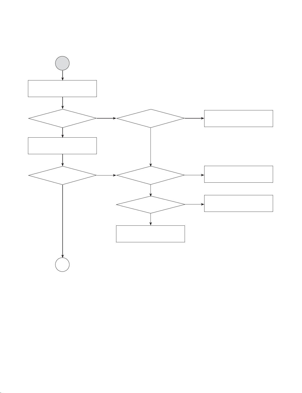
Page 18

C
Audio feature verification.
Plug AV-Cable in
Line out
function normal?
YES
Speaker out
normal?
YES
Plug headphone in
YES
Headphone
out normal?
NO
NO
NO
1. Check mute
control signal.
2. Check U12 setting. Pin15Shutdown, Pin21-Volume,
Pin22-HP/LINE,
Pine23-SE/BTL
YES
1. Check earphone
peripheral circuit.
2. Check U12 setting.
Pin22-HP/LINE,
Pine23-SE/BTL
Check 8202T
DAC out
YES
NO
Check Audio
peripheral circuit
YES
NO
1. Check audio
NO
relate circuit of
main chip.
2. Check Main chip.
NO
component value.
Check
YES
YES
D
Copyright © 2009 LG Electronics. Inc. All right reserved.
Only for training and service purposes
3-7
Check Jack,
connector
YES
Check cable
NO
Check open,
short, direction,
LGE Internal Use Only
pin define.
Page 19

D
USB feature.
USB detection?
YES
YES
USB playing.
NO
NO
USB
driver power?
YES
USB signal?USB file play?
NO
NO
Check USB power.
1. Check differential signal.
2. Check related circuit.
LGE Internal Use Only
3-8
Copyright © 2009 LG Electronics. Inc. All right reserved.
Only for training and service purposes
Page 20

RESET_B
+3.3V_SYS
C106
NC
U10
G692L263TCUF
2
3
1
4
RST
MR
GND VCC
+1.8V_SYS
C22
0.1U/25V/0402
L4
0/J/0603
C23
10U/6.3V/0805
C17
NC/10U/6.3V/0805
U16
LD1117AL-1.8V/SOT-223
2
1
3
4
VO
GND
VIN
VO2
Close IC
CLKOUT
CLKIN
R65
0/J/0402
C81
33P/50V/0402
Y2
27M/49US/DIP
R60
0/J/0402
R58
4.7K/F/0402
C71
33P/50V/0402
DETAILS AND WAVEFORMS ON SYSTEM TEST AND DEBUGGING
1. SYSTEM 27MHz CLOCK, RESET, FLASH SCK SIGNAL.
1-1. Main clock is at 27MHz(Y2)
1
1
FIG 1-1
1-2. Reset is active high.
2
3
FIG 1-2
3
2
Copyright © 2009 LG Electronics. Inc. All right reserved.
Only for training and service purposes
3-9
LGE Internal Use Only
Page 21

Debug Port
Debug_1
Debug_2
GNDA
CN8
NC/3P/
1
2
3
1-3. Waveform during procedure(Downloading)
SPI_CE
SPI_CLK_F
DQ0
DQ1
SPI_HOLD
SPI_WP
SPI_VCC3
U8
MX25L1636DM21-12G
1
2
3
4
5
6
7
8
CE#
DOUT
WP#
GND DIN
SCK
HOLD#
VDD
4
5
1-4. Flash SCK
6
5
4
FIG 1-3
LGE Internal Use Only
FIG 1-4
3-10
6
Copyright © 2009 LG Electronics. Inc. All right reserved.
Only for training and service purposes
Page 22

M_CLK
RAM_CLK
R95 33/F/0402
10P/50V/0402
C115
NC/10P/50V/0402
C112
RAM_CLK
M_BA0
M_BA1
SD_VCC3
37
38
20
6
12
46
52
21
CKE
CLK
BA0
VSSq
VSSq
VSSq
VSSq
BA1
2. SDRAM CLOCK
The Cover Limit Switch
COVER_SW
COVER_SW
GND_DC
GND_DC
SW1
A
C
C1
NC/VPORT0603102MV05
7
FIG 2-1
7
3. TRAY OPEN/CLOSE SIGNAL
8
Copyright © 2009 LG Electronics. Inc. All right reserved.
Only for training and service purposes
OPEN
CLOSE
FIG 3-1
3-11
8
LGE Internal Use Only
Page 23

CD5888CB
TCO
DMEA
SCO
SLED+
TR_B3
RAD-
VREF2
SLED-
RAD+
C55
0.1U/25V/0402
U4
AM5888S
15
21
19
20
24
27
28
17
18
16
23
22
25
26
G2
VOTK+
VCTL
VCC2
NC
NC
BIAS
MUTE
VOLD+
VOLD-
VOTK-
VINLD
GND
TRB2
VINTK
G2
R23 NC
R32
NC
R18 0/J/0402
R44
10K/F/0402
C24 0.1U/25V/0402
4. SLED CONTROL RELATED SIGNAL
9
10
11
FIG 4-1 < DVD >
SL+
SL-
TCO
109
9
10
11
LGE Internal Use Only
FIG 4-2 < CD >
SL+
SL-
TCO
3-12
11
Copyright © 2009 LG Electronics. Inc. All right reserved.
Only for training and service purposes
Page 24

VREF1
DVD-VR
E
DVD_VR
PUH-DVDLD
F
PUH-CDLD
CD_VRCD-VR
PUH_DVDLD
DVDMDI
CDMDI
PUH_CDLD
5V_RF_EMI
R165 0/J/0603
C163 0.1U/25V/0402
C164 0.1U/25V/0402
R160 0/J/0603
L5 1A/120OHM/0603
17
16
15
14
13
12
11
18
19
20
21
22
23
24
C20 100P/50V/0603
C11 100P/50V/0603
L7 1A/120OHM/0603
5. LASER POWER CONTROL RELATED SIGNAL
CD5888CB
REGO1
LOAD+
FCO
FOC-
REGO2
SP-
SPDCO
FOC+
F2
LOAD-
TR_B1
U4
AM5888S
1
9
10
12
3
2
15
7
14
13
21
19
20
24
27
6
4
5
28
8
11
17
18
16
23
22
25
26
G1G2
VINFC
VOTR-
VOTR+
VOSL-
REGO2
TRB1
VOTK+
REV
VOFC+
VOFC-
VCTL
VCC2
NC
NC
BIAS
FWD
VINSL+
REGO1
MUTE
VCC
VOSL+
VOLD+
VOLD-
VOTK-
VINLD
GND
TRB2
VINTK
G1
G2
C33
R44
CN5
MDI
12
CD_LD
13
DVD_LD
14
FIG 5-1
6. SPINDLE CONTROL WAVEFORM
15
SP-
13
12
14
17 15 16
16
17
Copyright © 2009 LG Electronics. Inc. All right reserved.
Only for training and service purposes
FIG 6-1
SP+
VOTK
3-13
LGE Internal Use Only
Page 25

7. FOCUS ON WAVEFORM
XOPVIP
SP+
REGO1
LOAD+
FCO
FOC-
REGO2
XOPVIN
SP-
SPDCO
FOC+
LOAD-
TR_B1
XOP
XOP
SP+
FCO
SPDCO
SP-
GNDM
+5V_M
1
9
10
12
3
2
7
14
13
6
4
5
8
11
G1
VINFC
VOTR-
VOTR+
VOSL-
REGO2
TRB1
REV
VOFC+
VOFC-
FWD
VINSL+
REGO1
VCC
VOSL+
G1
R187 1/F/0603
TP6
1
R33
10K/F/0402
R35
NC
C33 0.1U/25V/0402
TP5
1
18
19
20
F+
F-
FCO
18 19
U4
FIG 7-1 < DVD >
18
19
20
LGE Internal Use Only
FIG 7-2 < CD >
F+
F-
FCO
3-14
20
Copyright © 2009 LG Electronics. Inc. All right reserved.
Only for training and service purposes
Page 26

8. TRACKING CONTROL RELATED SIGNAL(System checking)
CD5888CB
TCO
DMEA
SCO
SLED+
TR_B3
RAD-
VREF2
SLED-
RAD+
C55
0.1U/25V/0402
U4
AM5888S
15
21
19
20
24
27
28
17
18
16
23
22
25
26
G2
VOTK+
VCTL
VCC2
NC
NC
BIAS
MUTE
VOLD+
VOLD-
VOTK-
VINLD
GND
TRB2
VINTK
G2
R23 NC
R32
NC
R18 0/J/0402
R44
10K/F/0402
C24 0.1U/25V/0402
21
22
23
21
2122
FIG 8-1 < DVD >
22
23
Copyright © 2009 LG Electronics. Inc. All right reserved.
Only for training and service purposes
FIG 8-2 < CD >
3-15
23
LGE Internal Use Only
Page 27

TSH-3997-2-PA66-J
AVOUT-DET_GND
AVOUT-DET
AVOUT-R
AVOUT-CVBS
AVOUT-L
C138
1000P/50
C127
100P/50V
G
L
R
V
J3
TC-38-363-16
1
2
3
4
5
6
7
C311
1000P/50
9. VIDEO OUTPUT WAVEFORM
TSH-3997-2-PA66-J
AVOUT-DET_GND
AVOUT-DET
AVOUT-R
AVOUT-CVBS
AVOUT-L
C138
1000P/50
C127
100P/50V
G
L
R
V
J3
TC-38-363-16
1
2
3
4
5
6
7
C311
1000P/50
24
FIG 9-1
24
A/V OUTPUT
10. AUDIO OUTPUT
25
FIG 10-1
LGE Internal Use Only
3-16
25
A/V OUTPUT
Copyright © 2009 LG Electronics. Inc. All right reserved.
Only for training and service purposes
Page 28

WIRING CONNECTION DIAGRAM
MAIN PCB <---> LCD PCB
LCD PCB
Copyright © 2009 LG Electronics. Inc. All right reserved.
Only for training and service purposes
3-17
MAIN PCB
LGE Internal Use Only
Page 29

BLOCK DIAGRAMS
1. OVERALL BLOCK DIAGRAM
DC-IN
Adaptor
Charger
Battery
7.4V/1900mA
3.3V
Flash 16Mbit(471)
Or 32Mbits (472)
3.3V
SDRAM
64Mbit
5V
USB
IR receiver
OZ522
+
2 D-D
DATA0..15
DP,DM
SPI
MA0..11
5V
3.3V
LD1117
1.8V
BUTTONS
KEY0--3
3.3V
1.8V
SUN+
SPHE8202T
SPDCO
IR
5V
Motor driver
CD5888
FOC+,FOC-
SLED+,SLED-
RAD+,RAD-
SP+,SP-
FCO
SCO
TCO
DMEA
3.3V
1.8V
SUN+
SPV518
S-VIDEO
I2C
AUD_FL
AUD_FR
Volume control
T-CON
R.G.B
VGH
VGL
VCOM
CVBS
5V
OP-APC558
OP_OUT_L,R
VR
6019_LIN,RIN
5V
Audio Amplifier
EUA6019
Analog Panel 7"
LED BL,
AV-OUT
Line out
Speaker
LGE Internal Use Only
LOADER
3-18
Earphone out
Copyright © 2009 LG Electronics. Inc. All right reserved.
Only for training and service purposes
Page 30

2. SYSTEM BLOCK DIAGRAM
Buttons
LED Power
Analog Panel 7"
LCD Translation Board
Flash 16Mbit
SDRAM 16Mbit
USB
IR receiver
DP,DM
IR
SUN+
SPHE8202T
Serve control
Motor driver
CD5888
LOADER
signal
KEY Matrix
I2C
L,R Line out
R,G,B
SUN+
SPV518
AUDIO L,R
Video
OP-
APC558
Audio L,R
EU6019
AV-OUT
Earphone out
Earphone out
Copyright © 2009 LG Electronics. Inc. All right reserved.
Only for training and service purposes
3-19
LGE Internal Use Only
Page 31

3. DC BLOCK DIAGRAM
QZ522
Charger
+
Battery
7.4V/1900mA
DC
Enable
2 D-D
Switch
LD1117
3.3V
1.8V
5V
Boost Circuit
PWM
SPV518
+10V
+16.5V
-10V
DVcc3.3V
DVcc1.8V
+5V_M
+5V_RF
+3.3V_RF
5V_AUD
VAA5V
+10V
+16.5V
-10V
SYSTEM
SERVO
Video, Audio
LCD Panel
LGE Internal Use Only
3-20
Copyright © 2009 LG Electronics. Inc. All right reserved.
Only for training and service purposes
Page 32

CIRCUIT DIAGRAMS
1. LCD I/F CIRCUIT DIAGRAM
CN6
SPK_R+_T
30
30
SPK_R-_T
29
29
SPK_L-_T
28
28
SPK_L+_T
27
27
KEY0_T
26
26
KEY1_T
25
25
KEY2_T
24
24
KEY3_T
23
23
IR-T
22
22
VCOM-T
21
21
STV-T
20
20
CKV-T
19
19
OEV-T
18
18
OEH-T
17
17
STH-T
16
16
GND
15
15
CPH1-T
14
14
13
13
VB-T
12
12
VG-T
11
11
VR-T
10
10
9
9
VGH-T
8
8
VGL-T
7
7
LED-T
6
6
LED+T
5
5
GND_DC
4
4
5-T
3
3
3.3-T
2
2
1
1
30P/1.0/VA/WAFER
C237
C242
NC/20P/50V/0402
C250
C245
NC/20P/50V/0402
NC/20P/50V/0402
C253
NC/20P/50V/0402
C261
C256
NC/20P/50V/0402
NC/20P/50V/0402
NC/20P/50V/0402
C262
NC/20P/50V/0402
NC/20P/50V/0402
NC/20P/50V/0402
C269
C265
C277
C273
C279
NC/20P/50V/0402
NC/20P/50V/0402
C251
NC/20P/50V/0402
C243
C249
NC/20P/50V/0402
NC/20P/50V/0402
NC/20P/50V/0402
C234
C238
C233
NC/20P/50V/0402
NC/20P/50V/0402
NC/20P/50V/0402
NC/20P/50V/0402
NC/20P/50V/0402
C327
C221
C227
NC/20P/50V/0402
C328
C329
C330
NC/20P/50V/0402
NC/20P/50V/0402
NC/20P/50V/0402
L17 0/J/0603
L16 0/J/0603
L13 0/J/0603
L64 0/J/0603
L53 0/J/0402
L54 0/J/0402
L70 0/J/0402
L56 0/J/0402
L58 0/J/0402
L71 0/J/0402
L59 0/J/0402
L61 0/J/0402
L62 0/J/0402
L63 0/J/0402
L65 0/J/0402
L78 0/J/0402
L76 0/J/0402
L74 0/J/0402
L73 0/J/0402
L77 0/J/0603
L75 0/J/0603
L69 0/J/0603
L68 0/J/0603
L67 0/J/0603
L66 0/J/0603
C229
0.1U/25V/0603
C220
C218
0.1U/25V/0603
SPK_R+
SPK_R-
C211
C212
0.1U/25V/0603
0.1U/25V/0603
0.1U/25V/0603
SPK_L-
SPK_L+
C202
0.1U/25V/0603
SPK_R+
SPK_R-
SPK_L-
SPK_L+
KEY0
KEY1
KEY2
KEY3
IR8202
PANEL_VCOM
STVD
CKV
OEV
OEH
STH
CPH1
PANEL_VB
PANEL_VG
PANEL_VR
PANEL_VGH
PANEL_VGL
LED-
LED+
+5V_BF
+3.3V_SYS
SPK_L+_T
SPK_L-_T
SPK_R+_T
SPK_R-_T
KEY0_T
KEY1_T
KEY2_T
KEY3_T
IR-T
VCOM-T
STV-T
CKV-T
OEV-T
OEH-T
STH-T
CPH1-T
VG-T
VB-T
VR-T
5-T
3.3-T
VGH-T
VGL-T
LED+T
LED-T
GND
GND_DC
1
TP88
1
TP89
1
TP90
1
TP87
1
TP82
1
TP77
1
TP78
1
TP80
1
TP73
1
TP81
1
TP74
1
TP68
1
TP66
1
TP67
1
TP65
1
TP71
1
TP63
1
TP62
1
TP64
1
TP83
1
TP84
1
TP75
1
TP79
1
TP76
1
TP70
1
TP85
1
TP101
GND_DC
Copyright © 2009 LG Electronics. Inc. All right reserved.
Only for training and service purposes
GNDA
3-21 3-22
GND_DC
LGE Internal Use Only
Page 33

2. OPU CIRCUIT DIAGRAM
+5V_RF
CN5
AF324K-A2G11/0.5/UP/FPC
1
2
3
4
5
6
7
8
9
10
11
12
13
14
15
16
17
18
19
20
21
22
23
24
5V_RF_EMI
F
FOC+_T
C
D
/LDSW
PUHRF
A
F
VREF1
E
CD-VR
DVD-VR
PUH-CDLD
PUH-DVDLD
G1 G2
T
-CO
_
DVDMDI
CDMDI
C165
0.1U/25V/0402
C164 0.1U/25V/0402
C163 0.1U/25V/0402
R165 0/J/0603
R160 0/J/0603
L7 1A/120OHM/0603
L5 1A/120OHM/0603
5V_RF_EMI
C351
100P/50V/0402
COF
FOC+
RAD+RAD+_T
-
RT_-DAR
DA
CD_VR
DVD_VR
1A/600OHM/0603
PUH_CDLD
C20 100P/50V/0603
PUH_DVDLD
C11 100P/50V/0603
L96
+5V_RF
C352
100P/50V/0402
Q23
2SK3018
CD_VR
DVD_VRB
Q22
2SK3018
+5V_RF
R150
10K/F/0402
S
G
R166
100K/F/0402
Q20
PMBS3904
EC
C160
0.1U/25V/0402
+5V_RF
C158
TC8
NC/47U/10V/B
22U/6.3V/0805
B
D
R164
D
G
S
C37
0.1U/25V/0402
R163
100K/F/0402
R17
5.1/F/0402
NC
12
+
TC2
47U/6.3V/A
EC
Q4
2SB1132
B
CDLDO
R159
10K/F/0402
R189
0/J/0402
C38
0.1U/25V/0402
2SB1132
LDSW
Q5
R19
5.1/F/0402
EC
RF3.3VRF3.3V
12
+
TC3
47U/6.3V/A
B
DVDLDO
PUH_DVDLDPUH_CDLD
OPUSW1
SLED-
SLED+
LGE Internal Use Only
SP-
SP+
L44 0/J/0603
L43 0/J/0603
L42 0/J/0603
R149 0/J/0402
C156 10P/50V/0603
C157 10P/50V/0603
L41 0/J/0603
L40 0/J/0603
SP-_T
SP+_T
SW1_T
SW2_T
SELD+_TSLED+
CN4
1
2
3
4
4P/2.0/RA/A2001
CN3
T_-DLES-DELS
1
2
2P/2.0/RA/A2001
TP26
TP28
TP25
TP27
TP21
TP24
TP29
TP43
TP37
TP30
TP32
TP34
TP23
FOC-_T
FOC+_T
RAD+_T
RAD-_T
1
1
1
1
1
1
1
1
1
1
1
1
1
SP-_T
SP+_T
SW1_T
SW2_T
SELD-_T
SELD+_T
/LDSW
CD-VR
DVD-VR
PUH-CDLD
PUH-DVDLD
GND
+5V_RF
3-23 3-24
C357 NC/470P/50V/0402
C356 NC/470P/50V/0402
C358 NC/470P/50V/0402
C359 NC/470P/50V/0402
TP33
TP38
TP47
TP48
TP51
TP35
TP42
TP50
TP49
TP44
TP22
TP69
TP39
TP8
TP31
TP7
FOC+
FOCRAD+
RAD-
1
1
1
1
1
1
1
1
1
1
1
1
1
1
1
1
FOC+_T
FOC-_T
RAD+_T
RAD-_T
A
B
C
D
E
F
VREF1
LDSW
PUHRF
CDLDO
DVDMDI
CDMDI
DVDLDO
FOC+
FOCRAD+
RAD-
A
B
C
D
E
F
VREF1
LDSW
PUHRF
CDLDO
DVDMDI
CDMDI
DVDLDO
Copyright © 2009 LG Electronics. Inc. All right reserved.
Only for training and service purposes
Page 34

3. HP/SPK AMP CIRCUIT DIAGRAM
+5V_AUD
C278
0.1U/25V/0402
GNDA
C281
10U/10V/0805
Power ON / OFF Mute
+3.3V_SYS
TC1
A K
GNDA
47U/10V/B
1N4148
+
D13
49.9K/F/0402
6019_RIN
GNDA
6019_LIN
OP_OUT_L
OP_OUT_R
R236
100/J/0402
R237
L81 0/J/0603
C286
0.1U/25V/0402
R239
10K/J/0402
Q33
B
PMBS3904
E C
R286 0/J/0402
R82 0/J/0402
R81 0/J/0402
R287 0/J/0402
C360 NC/1U/16V/0603
6019_RIN
6019_LIN
12
C334
NC/10U/10V/0805
GNDA
TP91
Reset
L:MUTE
H:ACTIVE
C302
NC
C343 NC/1U/16V/0603
C342 NC/1U/16V/0603
C361 NC/1U/16V/0603
GNDA
C348
C347
VPORT0603102MV05
VPORT0603102MV05
EC13
220U/10V/6.3*7.7/S
SPK_R-
SPK_L-
R281 0/J/0603
R282 0/J/0603
R283 0/J/0603
R284 0/J/0603
C367
0.1U/25V/0402
GNDA
SYS_MUTE
+
A K
SPK_R-
C287 1U/16V/0603
C100 33N/16V/0603
C288 33N/16V/0402
C289 33N/16V/0402
C99 33N/16V/0603
C290 1U/16V/0603
SPK_L-
C349
NC
C368
0.1U/25V/0402
GNDA
D15
1N4148
F/W control
VR_Rout
VR_Lout
C350
NC
C369
C370
0.1U/25V/0402
0.1U/25V/0402
GND_DC
GNDA
+5V_AUD
+5V_AUD
+5V_AUD
SW2
VR/50K/5PIN
1
1
2
2
3
3
4
4
5
5
L100
EC8
+
100U/16V/6.3*5.7/S
GND_DCGND_DC
SYS_MUTE (14)
IO_MUTE (19)
RHPIN
RLINEIN
LLINEIN
LHPIN
G1
G2
G1
G2
R288 0/F/1206
NC/10UH/1.49A/D63CB
L102 NC/10UH/1.5A/DS75LC
L95
0/J/0603
U12
EUA6019
1
PGND1
2
ROUT-
3
PVDD1
4
RHPIN
5
RLINEIN
6
RIN
7
VDD
8
LIN
9
LLINEIN
10
LHPIN
11
PVDD2
12
LOUT- PGND2
+5V_V
+5V_SYS_A
ROUT+
SE/BTL
HP/ LINE
VOLUME
SEDIFF
SEMAX
AGND
BYPASS
FADE
SHOTDOWN
LOUT+
GND
25
GNDA
SPK_R+
R222
NC/2.2M/F/0402
24
23
22
21
Headphone and speaker difference
20
Headphone max volume
19
(500ms Fade On)
18
17
16
15
14
SPK_L+
13
C298
+5V_AUD
R267
47K/F/0402
R270
100K/F/0402
VOL
1U/16V/0603
SYS_MUTE
VOL
GNDA
12
EC1
220U/6.3V/6.3*5.3/S
HP-ROUT
R126
1K/F/0402
GNDA
2.2M/F/0402
GNDA
L:MUTE
H:ACTIVE
12
EC2
220U/6.3V/6.3*5.3/S
R128
1K/F/0402
GNDA
SPK_R+
HP_R_OUT
R231
GNDA
R226
100K/F/0603
R223 100K/F/0402
R234 100K/F/0402
R230 NC
J
SPK_L+
HP_L_OUT
Q26
BAV70-F
K
A
100K/F/0402
GNDA
+5V_AUD
R229
+5V_AUD
R225
100K/F/0402
HP1_DET
HP2_DET
Copyright © 2009 LG Electronics. Inc. All right reserved.
Only for training and service purposes
GNDA
GNDA
3-25 3-26
LGE Internal Use Only
Page 35

4. AUDIO I/F CIRCUIT DIAGRAM
R90
AOUT_FL
180/F/0402
C108
10U/10V/0805
C104
220P/50V/0402
R92
7.5K/J/0402
R103
27K/F/0402
R102
4.7K/F/0402
C111
1200P/50V/0402
C292
NC
OPREF
R217
0/J/0402
C122
120P/50V/0402
R220
NC
2
1
V-
2
3
-
1
+
U13A
APC558KC
8 4
V+
OPVCC+
C296
0.1U/25V/0402
OP_OUT_L
C124
10U/10V/0805
+5V_SYS_A
C299
10U/10V/0805
OPVCC-
C291
0.1U/25V/0402
GNDA
L83
0/J/0603
C295
10U/10V/0805
2
R117
100K/F/0402
1
R115
1K/F/0402
2
-5V_SYS
R232
1K/F/0402
1
H:MUTE
L:ACTIVE
B
Q29
PMBS3904
E C
2
C129
1N/50V/0402
1
R122
0/J/0402
2 1
AVOUT_L
SYS_MUTE
AOUT_FR
L:MUTE
H:ACTIVE
R89
180/F/0402
R219
1K/J/0402
C103
220P/50V/0402
GNDA
C107
10U/10V/0805
+3.3V_SYS
B
R91
7.5K/J/0402
R218
4.7K/J/0402
Q25
PMBS3906
C E
R101
4.7K/F/0402
C110
1200P/50V/0402
R100
27K/F/0402
OPREF
C121
120P/50V/0402
GNDA
OP_OUT_R
OPVCC-
-
6
5
+
8 4
OPVCC+
7
U13B
APC558KC
C123
10U/10V/0805
1
R118
100K/F/0402
2
R114
1K/F/0402
R233
1K/F/0402
21
H:MUTE
L:ACTIVE
B
Q30
PMBS3904
E C
2
C128
1N/50V/0402
1
GNDA
R119
0/J/0402
21
AVOUT_R
LGE Internal Use Only
3-27 3-28
Copyright © 2009 LG Electronics. Inc. All right reserved.
Only for training and service purposes
Page 36

5. MOTOR DRIVE CIRCUIT DIAGRAM
RAD+
RAD-
SLED-
SLED+
+5V_M
RAD+
RADSLEDSLED+
R18 0/J/0402
R23 NC
C24 0.1U/25V/0402
15
16
17
18
19
20
21
U4
VOTK+
VOTKVOLD+
VOLDVCC2
NC
VCTL
G2
VOFC+
VOFC-
VOSL-
VOSL+
VOTR+
VOTR-
VCC
G1
14
13
12
11
10
9
8
G1G2
FOC+
FOC-
R187 1/F/0603
SPLOAD+
LOAD-
SP-
1
1
C33 0.1U/25V/0402
FOC+
FOC-
TP5
TP6
GNDM
XOPVIN
XOPVIP
SP+
+5V_M
XOPVIN
XOPVIP
SP+
+5V_M
C174
22U/6.3V/0805
C336
22U/6.3V/0805
VREF2
DMEA
C180
0.1U/25V/0603
C29
0.1U/25V/0402
SCO
TCO
TC12
NC/47U/10V/B
GNDM
SCO
TR_B3
TCO
VREF2
C55
R32
0.1U/25V/0402
NC
DMEA
R44
10K/F/0402
22
GND
23
VINLD
24
NC
25
TRB2
26
VINTK
27
BIAS
28
MUTE
AM5888S
CD5888CB
REV
FWD
REGO1
VINSL+
REGO2
TRB1
VINFC
7
6
5
4
3
2
1
REGO1
SPDCO
REGO2
TR_B1
FCO
SPDCO
FCO
R33
10K/F/0402
R35
R31
12K/F/0402
R28
0/J/0402
R25
0/J/0402
NC
Copyright © 2009 LG Electronics. Inc. All right reserved.
Only for training and service purposes
3-29 3-30
LGE Internal Use Only
Page 37

6. MEMORY CIRCUIT DIAGRAM
SD_VCC3
M_A0
M_A1
M_A2
M_A3
M_A4
M_A5
M_A6
M_A7
M_A8
M_A9
M_A10
M_A11
M_DQM0
M_DQM1
M_WE
M_CAS
M_RAS
RAM_CLK
M_BA0
M_BA1
23
24
25
26
29
30
31
32
33
34
22
35
15
39
16
17
18
19
37
38
20
21
12
46
52
6
U15
A0
A1
A2
A3
A4
A5
A6
A7
A8
A9
A10/AP
A11
LDQM
UDQM
WE
CAS
RAS
CS
CKE
CLK
BA0
BA1
VSSq
VSSq
VSSq
VSSq
M12L
NC/RFU
64164A-5TG
D0
D1
D2
D3
D4
D5
D6
D7
D8
D9
D10
D11
D12
D13
D14
D15
NC
VSS
VSS
VSS
VDD
VDD
VDD
VDDq
VDDq
VDDq
VDDq
2
4
5
7
8
10
11
13
42
44
45
47
48
50
51
53
36
40
28
41
54
1
14
27
3
9
43
49
M_D0
M_D1
M_D2
M_D3
M_D4
M_D5
M_D6
M_D7
M_D8
M_D9
M_D10
M_D11
M_D12
M_D13
M_D14
M_D15
SD_VCC3
SD_VCC3
C306
10U/6.3V/0805
M_CLK
C101
C297
C293
0.1U/25V/0402
0.1U/25V/0402
0.1U/25V/0402
R95 33/F/0402
C112
NC/10P/50V/0402
C303
C300
0.1U/25V/0402
0.1U/25V/0402
RAM_CLK
C115
10P/50V/0402
C98
C88
0.1U/25V/0402
0.1U/25V/0402
C304
0.1U/25V/0402
SPI Mode Setting
2bit 1bit
0R198 NC
R143 NC
0
M_DQM[0..1]
M_A[11..0]
M_D[15..0]
M_CAS
M_RAS
M_WE
M_BA0
M_BA1
M_CLK
SPI_D0
SPI_D1
SPI_CLK
SPI_CE
M_DQM[0..1]
M_A[11..0]
M_D[15..0]
M_CAS
M_RAS
M_WE
M_BA0
M_BA1
M_CLK
SPI_D0
SPI_D1
SPI_CLK
SPI_CE
LGE Internal Use Only
SPI_CE
DQ0
SPI_WP
SPI_VCC3
U8
1
CE#
2
DOUT
3
4
MX25L1636DM21-12G
R204 NC
HOLD#
WP#
GND DIN
VDD
SCK
8
7
6
5
For 1bit SPI Flash
R202 0/J/0402
R205 0/J/0402
R203 10K/F/0402
R66 10K/F/0402
SPI_HOLD
SPI_CLK_F
DQ1
1QD0QD
DQ0SPI_D0
DQ1SPI_D1
SPI_WP
SPI_HOLD
SPI_VCC3
SPI_VCC3
S
C80
0.1U/25V/0402
R69 33/F/0402
F_KLC_IP
C83
NC
C86
NC
KLC_IPS
3-31 3-32
Copyright © 2009 LG Electronics. Inc. All right reserved.
Only for training and service purposes
Page 38

7. MPEG CIRCUIT DIAGRAM
DVCC3
12
+
TC5
NC/47U/6.3V/A
R94 NC/20/J/0402
D7
R93
NC/1N4148
NC/10K/F/0402
R85
NC/20/J/0402
B
NEW 11.27 820P/50V/0402
C59
R86
NC/47/J/0402
R79 NC/2.2K/F/0402
Q14
NC/PMBS3904
E C
680P/50V/0402C56
1000P/50V/0402
0.1U/25V/0402C67
0.1U/25V/0402C69
Close to 8202T
RESET_B
C97
NC/1U/16V/0603
RF3.3V
TCO
FCO
RF3.3V
SPDCO
SCO
TP13
+3.3V_SYS
C106
NC
U10
G692L263TCUF
1
2
RESET_B
C94
0.1U/25V/0402
CDLDO
DVDMDI
CDMDI
VREF1
VREF2
100K/F/0603
R43 91K/F/0603
10K/F/0603
R53 2.2K/F/0603
R56 2.2K/F/0603
1
DMEA
OPUSW1
OPUSW2
IO_MUTE
AVOUT_DET
518RST
PWR_5V
KEY3
SPI_CE
SPI_D0
SPI_CLK
SPI_D1
COVER_SW
GND VCC
RST
MR
U9
103
CDLDO
104
DVDMDI
105
CDMDI
106
SRV_AVDD
107
V21
108
V165
109
DA_AVSS
110
DA_TEO
111
DA_FEO
112
DA_AVDD
113
SPDC_OUT
114
SC_OUT
115
DVDVR
116
DMEA
117
SD_D1/GPIO4
118
SD_D0/GPIO5
119
SD_CLK/GPIO6
120
TRAYIN/SD_SMD/GPIO7
121
TRAYOUT/SD_D3/GPIO8
122
SD_D2/GPIO9
123
CDVR
124
SPI_CE
125
SPI_D0
126
SPI_CLK
127
SPI_D1
128
TRAY+
+3.3V_SYS
518_SY
518_SC
4
3
A
B
FEXOPVIP
XOPVIN
DVDLDO
102
101
1009998979695949392919089888786858483828180
CDF
CDE
DVDA
OPVIP
OPVIN
DVDLDO
APC_AVSS
C
DVDB
DVDC
D
DVDD
PUHRF
0.1U/25V/0402C240
1U/16V/0603C66
RFIS
AGCCAP
RF3.3V
HOME
LDSW
AD_AVSS
AD_AVDD
LDSW/GPIO40
PLLVCC3
PLLVCC1.8
CLKOUT
CLKIN
CLKIN
VDD_18
CLKOUT
PLL_VDD
HOME/GPIO39
USB_PLLVCC3
USB_DP
USB_DM
79
78777675747372717069686766
USB_DP
USB_DM
PLL_VSS
USB_AVSS
USB_AVDD
VCC1.8
L18 33/F/0603
TV_DAC3
VDD_18
TV_AVSS
VVCC3
L20 33/F/0603
R253 75/F/0402
TV_DAC1
TV_DAC2
TV_DAC3
TV_DAC2
TV_DAC1
TV_AVDD
SPHE8202T
8202_CVBSTV_DAC0
VVCC3
L22 0/J/0603
V_FSADJ
TV_AVSS
TV_DAC0
TV_AVDD
AOUT_FR
AOUT_FL
L23 33/F/0603
L24 33/F/0603
V_COMP
AOUT_R
AOUT_L
65
AOUT_L
AOUT_R
V_COMP
V_FSADJ
ADAC_AVSS
ADAC_AVDD
CCIR656_CLK
CCIR656_D0
CCIR656_D1
CCIR656_D2
CCIR656_D3
CCIR656_D4
CCIR656_D5
CCIR656_D6
CCIR656_D7
SPDIF_OUT
M_BA1/GPIO27
VREF
GPIO38
M_A3
M_A2
M_A1
M_A0
M_A10
M_BA0
M_RAS
M_CAS
M_WE
M_DQM0
M_A4
Reserve
ADPIN_DET
AVOUT_DET
LED_ON
IO_MUTE
64
63
DAC_REF
62
TFT_CS
61
60
59
58
57
56
55
54
53
ADPIN
52
R291 0/J/0402
51
M_A3
50
M_A2
49
M_A1
48
M_A0
47
M_A10
46
M_BA1
45
M_BA0
44
M_RAS
43
M_CAS
42
M_WE
41
M_DQM0
40
M_A4
39
NC 0402C371
NC 0402C372
NC 0402C373
NC 0402C374
GNDA
GNDA
AVCC3
NCC320
NCC321
NCC322
NCC323
NCC109R48 2.2K/F/0603
NCC114
NCC113
NCC117
C280
0.1U/25V/0402
LED_ON
C365
0.1U/25V/0402
GNDA
C284
10U/6.3V/0805
R88 4.7K/F/0402
R83 4.7K/F/0402
R64 4.7K/F/0402
R215 10K/F/0402
R209 10K/F/0402
R212 10K/F/0402
R214 10K/F/0402
R1 10K/F/0402
R145 4.7K/F/0402
R245 NC/4.7K/F/0402
R273 4.7K/F/0402
518RST
USB_DM
USB_DP
518_SC
518_SY
8202_CVBS
AOUT_FR
AOUT_FL
IO_MUTE
R290 0/J/0402
ADPIN
PWR_5V
IR8202
TFT_CS
HOME
OPUSW2
SDRAM & FLASH
SPI_D0
SPI_D1
SPI_CE
SPI_CLK
M_D[15..0]
M_A[11..0]
M_DQM[0..1]
M_CAS
M_RAS
M_WE
M_BA0
M_BA1
M_CLK
I2C_DATA
I2C_CLK
AVOUT_DET
KEY3
KEY2
KEY1
KEY0
COVER_SW
OPUSW1
ADPIN_DET
518RST
USB_DM
USB_DP
518_SC
518_SY
AVOUT_CVBS
AOUT_FR
AOUT_FL
IO_MUTE
ADPIN_DET
0.1U/25V/0402C364
PWR_5V
IR8202
TFT_CS
PW_KEEP
PW_DET
SPI_D0
SPI_D1
SPI_CE
SPI_CLK
M_D[15..0]
M_A[11..0]
M_DQM[0..1]
M_CAS
M_RAS
M_WE
M_BA0
M_BA1
M_CLK
I2C_DATA
I2C_CLK
AVOUT_DET
KEY3
KEY2
KEY1
KEY0
COVER_SW
LED_ON
CN8
Debug Port
Debug_1
1
Debug_2
2
3
NC/3P/
RF3.3V
GPIO22
GPIO23
C241
0.1U/25V/0402
GNDA
R80 0/J/0402
R87 0/J/0402
C232
C239
0.01U/25V/0402
0.01U/25V/0402
DVCC3 VCC1.8 VVCC3
Close to 8202T
Copyright © 2009 LG Electronics. Inc. All right reserved.
Only for training and service purposes
Debug_1
Debug_2
C92
C274
0.01U/25V/0402
0.01U/25V/0402
C260
C264
0.1U/25V/0402
0.01U/25V/0402
C263
0.01U/25V/0402
VFD_CLK/GPIO16
VFD_STB/GPIO17
VFD_DATA/GPIO18
RESET_B
VDD_33
VSS
123105
46789
RESET_B
IR8202
KEY2
KEY0
KEY1
DVCC3
10U/6.3V/0805
VDD_18
M_DQM2/GPIO22
M_DQM3/GPIO23
M_D0
M_D1
M_D2
M_D3
M_D4
M_D5
M_D6
M_D7
M_D15
M_D14
M_D13
M_D12
M_D11
M_D10
M_D9
M_D8
M_D11
M_D10
KEY0
R213
NC/0/J/0402
M_D9
M_D8
M_DQM1
M_DQM1
IR/GPIO19
GPIO20
GPIO21
111213141516171819202122232425262728293031323334353637
M_D14
M_D12
M_D15
I2C_CLK
I2C_DATA
GPIO22
GPIO23
VCC1.8
C57
0.1U/25V/0402
M_D2
M_D0
M_D1
C52
10U/6.3V/0805
M_D3
M_D4
M_D5
M_D7
M_D6
2FERV1FERV
C60C49
0.1U/25V/0402
M_D13
3-33 3-34
VSS
M_CLK
M_CLK
VDD_33
DVCC3
M_A11/GPIO25
M_A9
M_A8
M_A7
M_A6
M_A9
M_A8
M_A7
M_A6
M_A11
M_A5
38
M_A5
C71
33P/50V/0402
Close IC
VVCC3
GNDA
R60
0/J/0402
R58
4.7K/F/0402
C267 10U/6.3V/0805
R210 1K/F/0402
R251 NC/75/F/0402
R252 NC/75/F/0402
R250 75/F/0402
Y2
27M/49US/DIP
V_COMP
V_FSADJ
TV_DAC1
TV_DAC3
TV_DAC0
R65
0/J/0402
C81
33P/50V/0402
CLKOUT
CLKIN
MOTOR
TCO
FCO
SPDCO
SCO
VREF2
DMEA
XOPVIN
XOPVIP
PUH
A
B
C
D
E
F
VREF1
LDSW
PUHRF
CDLDO
DVDMDI
CDMDI
DVDLDO
OPUSW1
TCO
FCO
SPDCO
SCO
VREF2
DMEA
XOPVIN
XOPVIP
A
B
C
D
E
F
VREF1
LDSW
PUHRF
CDLDO
DVDMDI
CDMDI
DVDLDO
OPUSW1
LGE Internal Use Only
Page 39

8. VIDEO CONTROLER CIRCUIT DIAGRAM
S-VEDIO INPUT
518_SY
518_SC
C362
470P/50V0402
I2C Adress Select
C363
470P/50V/0402
COMPA
COMPB
RSET
R182
6.8K/F/0402
C75
330P/50V0402
OEV
OEH
R184
6.8K/F/0402
L12 2.7uH/0.3mA/0805
L11 2.7uH/0.3mA/0805
C74
330P/50V/0402
R169 10K/F/0402
R170 10K/F/0402
R179 1K/F/0402
C54
330P/50V/0402
C179
Close to the 518A
R15 4.7K/F/0402
C30
27P/50V/0402
C53
2.2N/50V/0402
2.2N/50V/0402C185
Y1 27M/49US/DIP
R39
330P/50V/0402
75/F/0402
CKO
CKI
C21
27P/50V/0402
220N/10V/0402C50
220N/10V/0402C47
R38
75/F/0402
Y1
C1
ADC_VCC3
TP58
TP57
ADC_VCC3
TP52
1
SARIN_0
U3
SARIN0
TP54
1
1
TP55
C1
Y1
1U/16V/0603C186
1U/16V/0603C189
1U/16V/0603
C193
GPIO4
1
1
MOD OUTB
PWR_FM
POL
STVD
CKV
A0
1
2
A1
3
A2
4
A3
5
AVDD_ADC
6
AVSS_ADC
7
VCM
8
VRN
9
VRP
10
GPIO4/CCIR_BLANK
11
GPIO5/CCIR_VS
12
GPIO6/CCIR_HS
13
AP_Q1H/GPIO7
14
P_POL_PFRP
15
P_STVD
16
P_CLKV
IOVDD
PLL_VCC3
TP53
1
CKI
SARIN_1
636462
SARIN1
CKO
58
59
60
61
AVSS_PLL
AVDD_PLL
AVSS_ADC
AVDD_ADC
57
XOUT
SPV518A
DVDD0
DVSS0
P_GP1_OEV/I2C_ADR0
P_LP_OEH/I2C_ADR1
P_STHL
CPH3
19
18172021222324
SDA
56
XIN
SDA
CPH2
CPH1
25
518RSTT
SCL
54
55
SCL
RST
RSET
VBSP
27
26
50
51
52
53
CCIR656_D4
CCIR656_D5
CCIR656_D6
CCIR656_D7
CCIR656_CLK
BOUT
AVDD_VDAC
AVSS_VDAC
AOUT
312930
28
49
65
65
CCIR656_D3
IOVDD2
DVSS2
DVDD2
CCIR656_D2
CCIR656_D1
CCIR656_D0
PWM1
CCOM_A
FB_A
OUT_A
OUT_B
FB_B
CCOM_B
VSS1
VDD1
COUT
32
48
47
46
45
44
43
C331
42
41
40
39
38
37
36
35
34
33
NC
COMPA
FB_A
OUTA
FB_B
COMPB
IO_VCC3
DVDD1.8V
L8 33/F/0402
IO_VCC3
BL_PWM
PANEL T-COM
STVD
CKV
OEV
MOD
OEH
STH
CPH3
CPH2
CPH1
1
1
1
STVD
CKV
OEV
OEH
STH
CPH1
PANEL INPUT
VR
VG
VB
VR
VG
VB
I2C
I2C_DATA
I2C_CLK
VGL,VGL
OUTB
FB_B
OUTA
FB_A
PWR_FM
POL
BL_PWM
518_SY
518_SC
SARIN_0
SARIN_1
TP60
TP59
TP56
I2C_DATA
I2C_CLK
OUTB
FB_B
OUTA
FB_A
PWR_FM
POL
BL_PWM
518_SY
518_SC
BATLOW_DET
BAT_DET
Debug Port
TP98
TP99
TP100
C183
0.1U/25V/0402
LGE Internal Use Only
I2C_DATA
1
I2C_CLK
1
1
VDAC_VCC3
C197
0.1U/25V/0402
I2C_CLK
IO_VCC3ADC_VCC3
C188
0.1U/25V/0402
R158
R157
C199
0.1U/25V/0402
0/J/0402
0/J/0402
C182
0.1U/25V/0402
SDAI2C_DATA
SCL
C172
0.1U/25V/0402
VBSP
OEV
IO_VCC3
DVDD1.8V
OEH
CPH3
STH
C324
20P/50V/0402
CPH2
VB
RSET
0.1U/25V/0402C191
L60 33/F/0402
CPH1
VDAC_VCC3
VG
VR
VDAC_VCC3
3-35 3-36
0.1U/25V/0402
518RSTT
C337
R274 0/J/0402
Copyright © 2009 LG Electronics. Inc. All right reserved.
C187
0.1U/25V/0402
518RST
Only for training and service purposes
Page 40

9. AV I/F CIRCUIT DIAGRAM
J3
TC-38-363-16
L
R
V
A/V OUTPUT
AVOUT-L
1
2
AVOUT-DET
4
AVOUT-DET_GND
5
AVOUT-R
3
AVOUT-CVBS
6
G
7
GNDA
HP2 OUT
J2
TC38-010-121-TF
HP1 OUT
J1
TC38-010-121-TF
E
G
F
D
C
E
G
F
D
C
TSH-3997-2-PA66-J
C127
100P/50V/0603
HPLOUT
HP1-DET
HPROUT
C138
1000P/50V/0603
TP95
1
C312
1000P/50V/0603
TP92
1
R144
NC
11.27 DEL
C311
1000P/50V/0603
GND_DC
1
TP93
1
C140
1000P/50V/0603
11.27 DEL
L85
1A/120OHM/0603
TP94
L34 1A/120OHM/0603
L86 3.3/F/0603
R130 1K/F/0603
L33 1A/120OHM/0603
L30 1A/120OHM/0603
R104
VPORT0603102MV05
GNDA
L37 1A/120OHM/0603
L87 3.3/F/0603
L36 1A/120OHM/0603
GNDA
C308
NC/10P/50V/0402
GNDA
C133
NC/10P/50V/0402
GNDA
C309
NC/10P/50V/0402
ADD 11.27 1000P/50V/0402
R132 22/F/0402
R129 22/F/0402
R121 75/F/0402
R120 75/F/0402
C134
ADD 11.27 1000P/50V/0402
NC/10P/50V/0402
HP2_DET
HP_L_OUT
HP1_DET
HP_R_OUT
AVOUT_L
AVOUT_DET
AVOUT_R
AVOUT_CVBS
11.27 DEL
TP96
1
GNDA
Headphone out
Copyright © 2009 LG Electronics. Inc. All right reserved.
Only for training and service purposes
C313
1000P/50V/0603
R107
0/J/0805
R73
0/J/0603
C314
C315
1000P/50V/0603
1000P/50V/0603
GND_DC
ISOLATOR
C141
NC/10P/50V/0402
GNDA
3-37 3-38
C310
NC/10P/50V/0402
C139
NC/10P/50V/0402
ADD 11.27 1000P/50V/0402
LGE Internal Use Only
Page 41

10. USB I/F CIRCUIT DIAGRAM
TP10
TP9
CN7
1
1
2
3
4
5
R261 0/J/0603
1
TP11
1
5V_USB
D-_USB
D+_USB
GND
R183
0.1/F/1206
C58
10P/50V/0603
L52
1A/600OHM/0603
C203
0.1U/25V/0402
L14 NC
3
2
C62
10P/50V/0603
C196
0.1U/25V/0402
R47 1A/120OHM/0603
4
1
R52 1A/120OHM/0603
C77
10P/50V/0402
+5V_SYS
C192
10U/6.3V/0805
C72
10P/50V/0402
R57
15K/F/0402
R61
15K/F/0402
R63 33/F/0603
R67 33/F/0603
USB_DM
USB_DP
5P/1.25/RA/LM103
G1 G2
1
C353
VPORT0603102MV05
TP12
1
M5
LGE Internal Use Only
3-39 3-40
Copyright © 2009 LG Electronics. Inc. All right reserved.
Only for training and service purposes
Page 42

11. LCD POWER CIRCUIT DIAGRAM
R180 4.7/F/0603
PWR_5V
C201
+5V_V
R277
100K/J/0402
R278
10K/J/0402
NC
VAA5
R181
200K/F/0603
FDN302P
S
B
R186
Q43
G
Q44
PMBS3904
VCC_BIAS
C213
150K/F/0603
D
10U/10V/0805
C205
10U/10V/0805
+5V_BF
C345
0.1U/25V/0402
10U/10V/0805
+3.3V_SYS
C346C344
0.1U/25V/0402
L48 0/J/0603
10U/6.3V/0805
L55 0/J/0603
10U/6.3V/0805
L49 0/J/0603
10U/6.3V/0805
C177
C225
C195
IO_VCC3+5V_BF
C176
0.1U/25V/0402
ADC_VCC3
C215
0.1U/25V/0402
PLL_VCC3
C178
0.1U/25V/0402
+1.8V_SYS
L46 0/J/0603
DVDD1.8V
C166
10U/6.3V/0805
C169
0.1U/25V/0402
+3.3V_SYS
10U/6.3V/0805
GND_DC
C19
E C
GND_DC
U16
LD1117AL-1.8V/SOT-223
VO
VO2
2
4
C64
0.1U/25V/0603
3
VIN
GND
1
L50 0/J/0603
10U/10V/0805
C23
10U/6.3V/0805
VDAC_VCC3
C190
C17
NC/10U/6.3V/0805
C181
10U/10V/0805
C22
0.1U/25V/0402
L4
0/J/0603
+1.8V_SYS
Copyright © 2009 LG Electronics. Inc. All right reserved.
Only for training and service purposes
3-41 3-42
LGE Internal Use Only
Page 43

12. MPEG POWER CIRCUIT DIAGRAM
+5V_SYS
R147
1A/600OHM/0603
L47
0/J/0603
+5V_M
GNDM
+5V_RF
C159
0.1U/25V/0402
C184
0.1U/25V/0402
+3.3V_SYS
R206
0/J/0603
0.1U/25V/0402
L79
0/J/0603
C276
10U/6.3V/0805
L72
0/J/0603
10U/6.3V/0805
L57
0/J/0603
PLLVCC3
C252
VVCC3
C283
10U/6.3V/0805
USB_PLLVCC3
C257
RF3.3V
C259
10U/6.3V/0805
C271
0.1U/25V/0402
C266
NC/10U/6.3V/0805
0.1U/25V/0402
+1.8V_SYS
C255
0.1U/25V/0402
L51
0/J/0603
C214
0.1U/25V/0402
VCC1.8
C206
10U/6.3V/0805
R197
0/J/0603
C244
0.1U/25V/0402
PLLVCC1.8
C254
10U/6.3V/0805
10U/6.3V/0805
R216
0/J/0603
C272
10U/6.3V/0805
L21
0/J/0603
C91
10U/6.3V/0805
L15 0/J/0603
L84 0/J/0603
C217
AVCC3
DVCC3
SPI_VCC3
SD_VCC3
TC7
47U/6.3V/A
C275
10U/6.3V/0805
C96
10U/6.3V/0805
C268
0.1U/25V/0402
GNDA
C95
0.1U/25V/0402
C228
C226
0.1U/25V/0402
close to
8202T
LGE Internal Use Only
3-43 3-44
Copyright © 2009 LG Electronics. Inc. All right reserved.
Only for training and service purposes
Page 44

13. INPUT POWER CIRCUIT DIAGRAM
J4
DCJ-01-BLACK
G1G2
GND_DC
C149
10P/50V/0603
1
2
3
LED_ON7
L97 NC/0R/J/1206
1 2
L98 DLW5BTN102SQ2
L99 NC/0R/J/1206
C338
NC/VPORT0603102MV05
LED_ON
0.1U/25V/0402
34
ADPIN_DET
NEW 11.27
NC 11.27
C366
VCC_ADP
R296
10K/F/0402
R247
1K/F/0402
R248
1K/F/0402
LED_STAT
R221
10K/F/0402
B
1K/F/0402
C152
0.1U/25V/0603
VCC_ADP
B
Q28
PMBS3904
E C
GND_DC
R249
B
AK
C153
1N/50V/0603
VCC_ADP
R235
1K/F/0402
Q27
PMBS3904
E C
680R/F/0402
Q36
PMBS3904
E C
GND_DC
+
D16
1N4148
R241
100K/F/0402
B
R71
Q19
RSQ035P03
1
2
5
6
Q34
PMBS3904
E C
+5V_V
R224
680R/F/0402
Q24
PMBS3904
E C
321
LED1
LEG42292PF
4
3
R240
47K/F/0402
B
R137
100K/F/0402
R295
10K/F/0402
R246
1K/F/0402
R112
200K/F/0603
BAT_DET
R127
47K/F/0603
NEW 11.27
LED_ON
R134
2K/F/0603
D14
UDZSTE-1713B
A K
B
R238
1K/F/0603
R124
100K/F/0603
Q32
PMBS3904
E C
R123
10K/F/0603
Q31
B
PMBS3904
E C
C301
10U/10V/0805
R228
0/J/0603
Q16
RSQ035P03
4
3
C135
0.1U/50V/0603
VCC_ADP
1
2
5
6
Copyright © 2009 LG Electronics. Inc. All right reserved.
Only for training and service purposes
3-45 3-46
GND_DC
LGE Internal Use Only
Page 45

14. B/L POWER CIRCUIT DIAGRAM
TCON-VCC5
OUTB
OUTA
OUTB
TC4
47U/10V/B
C4
10U/10V/0805
C28 0.1U/25V/0402
R16 1K/F/0402
FB_B
TCON-VCC5
33u/600mA
L2 33UH/0.61A/D53LC
D1 D-1N5819
DS
G
Q2
APM2308A
G
FB_B
C12
22U/16V/1210
1U/16V/0603
15u/480mA
L6
15UH/0.88A/D53LC
DS
Q3
1K/F/0603
APM2300
D2 1N4148
1N/50V/0402
R20 0/J/0603
1N/50V/0402
C170
R152
C42
C34
D11 1N4148
D8
1N4148
C161
NC/1U/16V/0603
R21
100K/F/0402
R22
8.66K/F/0402
AK
C167
10u/16V/1206
C32
4.7u/25V/1206
D10
C171
NC/UDZS10B
C40
0.1U/25V/0402
PANEL_VGL
0.1U/25V/0402
PANEL_VGH
VCOM
POL8
IO_VCC3
5.1K/F/0402
R176
5.1K/F/0402
C175
POL
10U/10V/0805
100K/J/0402
R12
10K/F/0402
VCOMDC
R168
R178
U1
TC33X-2-503
R10
NC/10K/F/0402
Contrl the Backlight Power On/Off
LED+
C13
C16 R254
C7
22U/16V/1210
1N/50V/0402
0.1U/25V/0402
FB_A
1N/50V/0402
C14
D9
UDZS10B
A K
R162 1K/F/0603
R154
39/F/0603
LED-
R156
39/F/0603
TC6
22U/10V/A
C168
1N/50V/0402
TFT_CS8
R255
1K/F/0402
U2
NC/TC33X-2-503
3
R174
NC/04
VCOM_ADJ
50K
2
B
50K
1 2
R173
4.7K/J/0402
R6 1K/J/0402
13
R8
NC/48K/F/0402
+5V_SYS +5V_SYS
10K/F/0402
G
Q38
PMBS3904
E C
VCOM_OP
OUT2
IN2-
Q37
APM2301A
VCC_VCOM_OP
V+
U5
UTC3308L/SO8
1
OUT1
2
IN1-
3
IN1+
4 5
GND IN2+
SD
L1 0/J/0603
PANEL_VCOM
C194
10u/16V/1206
8
7
6
R171
4.7K/J/0402
C8
10U/10V/0805
LED+
R14
4.7K/J/0402
R175
560/F/0402
VCOMDC
TCON-VCC5
C325
C6
0.1U/25V/0402
10U/10V/0805
L90
VCC_VCOM_OP
0/J/0603
C26
10u/16V/1206
R172
4.7K/J/0402
C2
0.1U/25V/0402
C319
0.1U/25V/0603
LGE Internal Use Only
BL_PWM
R4 1K/J/0402
C9
1U/16V/0603
R5 169R/J/0603
C15
4.7U/6.3V/0603
3-47 3-48
Copyright © 2009 LG Electronics. Inc. All right reserved.
Only for training and service purposes
Page 46

15. CHARGER POWER CIRCUIT DIAGRAM
VIN_SYS
VCC_ADP
C119
0.1U/25V/0402
GND_DC
EN_DISABLE
0.01U/25V/0402
R105
2.7K/J/0402
C248
D
Q11
APM2301A
EC5
47U/25V/6.3*5.7/S
GND_DC
EN
R201
NC/0/J/0402
R193
56K/F/0402
C246
560P/50V/0402
D5
B240
S
G
+
47U/25V/6.3*5.7/S
LED_STAT
R194
10K/F/0402
C247
1N/50V/0402
C89
10N/50V/0402
EC6
+
R78
2.2M/F/0402
R75
49.9K/F/0402
15
7
8
5
6
9
CCVDNG
CHIGH
ST
EN
COMP2
COMP1
LV
13 14
S
R76
0/J/0402
2
CSN2
CSN1
20
Q12 APM2301A
D
D6
G
B240
16
GND_DC
12
SEN
HDR
11
BAT
17
DR2
1
CSP2
4
FB2
18
DR1
19
CSP1
3
FB1
THM
10
U6
UNICORN20-A
L29
10UH/1.14A/D63LCB
C120
560P/50V/0402
R99
5.1/F/0402
R70 0/J/0402
G
R211
0.1/F/1206
R207
100/F/0402
C258
2.2N/50V/0402
G
Q9
APM2301A
C68
560P/50V/0402
R45
5.1/F/0402
SD
Q15
R208
100/F/0402
SD
D3
B240
APM2301A
C79
10U/16V/1206
EC3
+
47U/25V/6.3*5.7/S
C118
0.1U/25V/0402
GND_DC
L10 10UH/1.5A/DS75LC
R50
15K/F/0402
EC4
+
47U/16V/6.3*5.7/S
C73
1U/16V/0603
R49
15K/F/0402
GND_DC
GND_DC
C116
0.1U/25V/0402
R98
82K/F/0402
BATLOW_DET
R97
56K/F/0402
C5
0.1U/25V/0402
GND_DC
C65
EC9
+
330P/50V/0402
100U/16V/6.3*5.7/S
+5V_V
R191
49.9K/F/0402
EC12
+
470U/16V/8*12/D
R200
12.4K/F/0402
GND_DC
R289 NC/0/F/1206
L101
33UH/0.8A/D63CB
Temp
C46
0.1U/25V/0402
+5V_SYS
TC13
47U/10V/B
TP102
TP103
1
1
C354
0.1U/25V/0402
J
GND_DCGND_DC
TP104
1
C355
0.1U/25V/0402
Q6
BAT54
G1G2
1
BAT +
2
BAT -
3
Temp Sensor
CN2 3P/2.0/RA/A2001
A
C326
K
10U/10V/0805
-5V_SYS
C44
C43
0.1U/25V/0603
0.1U/25V/0402
GND_DC
C230
10U/10V/0805
Copyright © 2009 LG Electronics. Inc. All right reserved.
Only for training and service purposes
R190 19.6K/F/0402
R192
5.1M/F/0402
R272
280K/F/0402
Temp
C236
560P/50V/0402
R77
0/J/0402
C93
560P/50V/0402
R84
5.1/F/0402
SD
G
Q13
FDN302P
D4
B140
C84
10U/16V/1206
L19 10UH/1.14A/D63LCB
R74
15K/F/0402
C87
1U/16V/0603
R72
15K/F/0402
+
EC10
100U/16V/6.3*5.7/S
C85
0.1U/25V/0402
GND_DC
3-49 3-50
+
EC11
100U/16V/6.3*5.7/S
C341
C335
0.1U/25V/0402
10U/10V/0805
+3.3V_SYS
R198
49.9K/F/0402
R199
21.5K/F/0402
LGE Internal Use Only
Page 47

16. SWITCH & VIDEO BUFFER CIRCUIT DIAGRAM
VG
150/F/0402
VB
150/F/0402
R34
R42
TC9
12
+
22U/10V/1206
TC10
12
+
22U/10V/1206
R40
3.9K/F/0402
R36
1K/F/0402
R51
3.9K/F/0402
R46
1K/F/0402
R54
390/F/0402
B
R62
390/F/0402
B
VAA5
C78 10U/10V/0805
Q8
PMBS3904
E C
R59
100/F/0402
VAA5
C82 10U/10V/0805
Q10
PMBS3904
E C
R68
100/F/0402
VCC_BIAS
R188
10K/F/0402
PANEL_VG
VCC_BIAS
R195
10K/F/0402
PANEL_VB
PANEL_VG
C207
NC/10U/10V/0805
PANEL_VB
C219
VAA5
C210
10U/10V/0805
VAA5
NC/10U/10V/0805
C224
10U/10V/0805
VIN_SYS
VCC_BIAS
C222
0.1U/25V/0603
PW_DET(14)
VCC_BIAS
C231
0.1U/25V/0603
C223
0.1U/25V/0603
C235
0.1U/25V/0603
R142 1K/F/0603
1 2
GNDA
RF3.3V
Q45
PMBS3904
GNDA GNDA
1 2
R109 1K/F/0603
R146
10K/F/0402
B
1
E C
R279
10K/F/0402
PW_ON/OFF
C148
NC/VPORT0603102MV05
PW_ON/OFF
2
C147
NC/VPORT0603102MV05
PW_KEEP
C340
0.1U/25V/0402
OFF
1
2
3
ON
C146
NC/VPORT0603102MV05
GNDA
D17
1N4148
D18
1N4148
SW3
SKB-12F03-G3-NS
POWER
SWITCH
12
EN_DISABLE
R280
47K/J/0402
VR
R26
150/F/0402
LGE Internal Use Only
TC11
1
2
+
22U/10V/1206
R30
3.9K/F/0402
R27
1K/F/0402
390/F/0402
Q7
PMBS3904
B
VAA5
R37
E C
C63 10U/10V/0805
R41
100/F/0402
VCC_BIAS
R185
10K/F/0402
PANEL_VR
PANEL_VR
C200
NC/10U/10V/0805
VAA5
C198
VCC_BIAS
C208
C204
0.1U/25V/0603
10U/10V/0805
0.1U/25V/0603
3-51 3-52
The Cover Limit Switch
COVER_SW
SW1
A
C1
NC/VPORT0603102MV05
C
GND_DC
GND_DC
COVER_SW
Copyright © 2009 LG Electronics. Inc. All right reserved.
Only for training and service purposes
Page 48

CIRCUIT VOLTAGE CHART
MODE
PIN NO.
STOP PLAY
U9(SPHE8202T)
1 3.353 3.207
2 3.352 3.206
3 3.347 3.208
4 3.184 3.065
5 3.195 3.060
6 0.077 0
7 3.372 3.292
8 3.061 3.077
9 3.080 3.109
10 1.803 1.702
11 0.081 0
12 0.085 0
13 0.460 0.424
14 0.485 0.436
15 0.487 0.473
16 0.456 0.432
17 0.476 0.432
18 0.263 0.254
19 0.187 0.166
20 0.345 0.315
21 0.385 0.327
22 0.201 0.102
23 0.283 0.195
24 0.378 0.333
25 0.353 0.325
26 0.363 0.358
27 0.496 0.402
28 0.502 0.451
29 1.884 1.765
30 0.082 0
31 1.753 1.659
32 3.188 3.124
33 0.094 0.045
34 0.100 0.056
35 0.143 0.065
36 0.218 0.156
37 0.239 0.223
38 0.236 0.215
39 0.253 0.115
40 1.876 1.556
41 2.972 2.981
42 2.957 2.831
43 2.991 2.960
44 0.287 0.217
45 0.100 0.096
46 0.110 0.036
47 0.128 0.117
48 0.282 0.187
49 0.164 0.144
50 0.083 0.077
51 3.073 3.028
52 3.325 3.277
53 3.151 3.106
54 0.079 0
55 0.076 0
56 0.069 0
57 0.070 0
MODE
PIN NO.
58 0.680 0
59 0.770 0
60 0.750 0
61 3.089 3.027
62 1.083 1.010
63 3.170 3.103
64 0.063 0
65 1.091 1.014
66 1.091 1.011
67 1.352 1.275
68 0.652 0.639
69 3.129 3.102
70 3.148 3.108
71 0.052 0
72 3.146 3.107
73 0.376 0.357
74 0.050 0
75 0.703 0.673
76 0.050 0
77 1.772 1.705
78 3.153 3.102
79 0.057 0
80 0.059 0
81 0.057 0
82 0.061 0
83 3.158 3.108
84 1.597 1.533
85 1.605 1.552
86 1.777 1.704
87 3.168 3.120
88 3.155 3.101
89 0.054 0
90 3.169 3.121
91 1.267 0.994
92 2.102 2.020
93 2.097 2.035
94 2.097 2.032
95 2.101 2.092
96 2.100 2.085
97 2.101 2.064
98 2.099 2.060
99 3.187 3.174
100 3.189 3.167
101 0.051 0
102 3.162 2.338
103 3.163 3.114
104 0.043 0.173
105 0.043 0.173
106 3.171 3.120
107 2.113 2.048
108 1.598 1.533
109 0.056 0
110 1.575 1.572
111 1.575 1.532
112 3.168 3.123
113 1.615 1.376
114 1.615 1.610
115 0.062 0
STOP PLAY
MODE
PIN NO.
116 3.192 3.113
117 3.191 3.123
118 0.062 0
19 3.193 3.122
120 0.583 0.563
121 3.159 3.123
122 3.151 3.114
123 3.303 3.258
124 0.126 0.057
125 1.379 1.321
126 1.419 1.213
127 1.478 1.233
128 3.325 3.112
STOP PLAY
U16(LD1117AL-1.8V)
1 0.058 0
2 1.819 1.749
3 3.248 3.196
4 1.819 1.750
U3(SPV518A)
1 0.000 0
2 0.057 0
3 1.501 1.258
4 1.072 1.021
5 3.329 3.283
6 0.055 0
7 1.548 1.491
8 1.068 1.002
9 2.066 2.001
10 3.324 3.276
11 3.325 3.279
12 3.324 3.277
13 1.678 1.521
14 1.688 1.479
15 0.054 0
16 0.232 0.172
17 3.324 3.277
18 0.052 0
19 1.813 1.742
20 1.889 0.832
21 0.105 0.047
22 0.062 0
23 1.543 1.645
24 1.687 1.658
25 1.746 1.703
26 1.397 1.356
27 0.623 0.608
28 0.685 0.620
29 3.322 3.278
30 0.052 0
31 0.691 0.623
32 0.684 0.614
33 3.324 3.278
34 0.053 0
35 0.093 0.020
36 1.266 1.195
37 0.197 0.153
38 1.877 1.842
39 1.242 1.845
MODE
PIN NO.
40 0.285 0.2
41 0.893 0.843
42 0.000 0
43 0.000 0
44 0.000 0
45 0.000 0
46 1.814 1.742
47 0.052 0
48 3.323 3.274
49 0.000 0
50 0.000 0
51 0.000 0
52 0.000 0
53 0.000 0
54 2.934 3.115
55 2.933 3.063
56 2.933 3.089
57 1.689 1.623
58 1.697 1.658
59 0.052 0
60 3.327 3.282
61 0.052 0
62 3.326 3.283
63 1.707 1.586
64 0.569 0.556
STOP PLAY
U4(AM5888S)
1 1.579 1.529
2 0.080 0.019
3 0.438 0.446
4 1.606 1.379
5 0.456 0.464
6 0.05 0
7 0.066 0
8 5.061 4.957
9 0.065 0
10 0.059 0
11 2.458 1.303
12 2.312 1.397
13 2.453 3.373
14 2.454 2.463
15 2.446 2.312
16 2.450 2.451
17 1.338 2.437
18 2.453 2.401
19 5.060 2.375
20 0.416 4.965
21 5.058 4.972
22 0 0
23 1.604 1.534
24 5.031 4.752
25 0.081 0.015
26 1.600 1.518
27 1.605 1.531
28 0.071 3.107
U5(UTC3308L)
1 2.954 2.875
2 1.504 1.411
3 1.141 1.035
MODE
PIN NO.
4 0.059 0
5 2.135 2.01
6 2.142 2.092
7 2.379 2.31
8 5.669 10.668
STOP PLAY
U6(UNICORN20-A)
1 5.062 4.920
2 5.060 4.948
3 1.050 5.051
4 1.049 1.048
5 2.081 2.008
6 1.684 1.669
7 5.669 7.292
8 5.669 7.176
9 5.669 5.863
10 5.669 5.737
11 1.388 1.404
12 1.353 1.361
13 0.052 0
14 0.669 8.471
15 3.434 3.28
16 5.669 8.447
17 4.354 5.367
18 4.735 6.356
19 3.368 3.228
20 3.352 3.235
U8(MX25L1636DM21-12G)
1 0.114 0
2 1.741 1.161
3 3.178 3.093
4 0.066 0
5 1.761 3.129
6 1.371 0.819
7 3.175 3.092
8 3.178 3.122
U12(EUA6019)
1 0.063 0
2 0.064 0
3 5.073 0.001
4 0.062 0
5 0.068 2.423
6 0.067 2.446
7 5.075 5.001
8 0.069 2.449
9 0.071 2.451
10 0.000 0
11 5.061 0.003
12 0.071 2.512
13 0.063 0
14 0.067 2.493
15 0.572 3.071
16 0.063 0
17 0.063 2.168
18 0.063 0
19 5.018 4.559
20 0.062 0
21 3.435 3.278
22 5.057 0
MODE
PIN NO.
23 0.106 0.035
24 0.063 2.521
STOP PLAY
U13(APC558KC)
1 0.071 0
2 0.071 0
3 0.072 0
4 -8.281 -8.243
5 -8.015 -0.11
6 0.041 0
7 0.034 0
8 0.401 0.001
U15(M12L64164A-5TG)
1 3.185 3.041
2 0.425 0.960
3 3.185 3.053
4 0.423 0.549
5 0.037 0.607
6 0.478 0
7 0.325 0.263
8 3.188 0.503
9 0.352 3.044
10 0.365 0.575
11 0.169 0.667
12 0.057 0
13 0.383 0.325
14 3.188 3.029
15 1.843 2.517
16 3.045 2.962
17 2.962 2.956
18 3.101 2.980
19 0.057 0
20 0.271 0.213
21 0.069 0.033
22 0.108 0
23 0.107 0.025
24 0.152 0.036
25 0.170 0.137
26 0.139 0.145
27 3.195 3.075
28 0.056 0
29 0.216 0
30 0.297 0.1
31 0.195 0.140
32 0.241 0.132
33 0.125 0
34 0.073 0.027
35 0.064 0
36 0.033 0
37 3.186 3.056
38 1.762 1.712
39 1.627 2.369
40 0.033 0
41 0.053 0
42 0.592 0.873
43 3.186 3.056
44 5.415 0.873
45 5.277 0.616
46 0.053 0
MODE
PIN NO.
47 0.294 0.659
48 0.329 0.927
49 3.187 3.054
50 0.259 0.876
51 0.130 0.769
52 0.052 0
53 0.364 0.750
54 0.053 0
STOP PLAY
Copyright © 2009 LG Electronics. Inc. All right reserved.
Only for training and service purposes
3-53 3-54
LGE Internal Use Only
Page 49

MODE
PIN NO.
STOP PLAY
Q2(APM2308A)
Drain 4.882 4.916
Gate 1.82 1.811
Source 0 0
Q3(APM2300)
Drain 4.937 4.951
Gate 0.098 0.135
Source 0 0
Q4(2SB1132)
Emitter 3.215 3.068
Collector 0.035 0.025
Base 3.209 3.021
Q5(2SB1132)
Emitter 3.222 2.928
Collector 3.201 2.241
Base 3.21 2.322
Q6(BAT54)
Drain -3.366 -3.181
Gate -8.916 -8.240
Source 0 0
Q7(PMBS3904)
Emitter 0.485 0.388
Collector 3.569 3.366
Base 1.049 1.039
Q8(PMBS3904)
Emitter 0.448 0.323
Collector 3.637 3.342
Base 1.066 1.072
Q9(APM2301A)
Drain 4.991 4.86
Gate 7.847 5.458
Source 8.719 8.489
Q10(PMBS3904)
Emitter 0.445 0.386
Collector 3.615 3.481
Base 1.062 1.053
Q11(APM2301A)
Drain 8.891 8.847
Gate 8.151 8.110
Source 8.577 8.488
Q12(APM2301A)
Drain 1.315 1.361
Gate 8.568 8.474
Source 8.578 8.490
Q13(FDN302P)
Drain 3.325 3.315
Gate 6.444 6.351
Source 8.575 8.482
Q14(PMBS3904)
Emitter 0.074 0
Collector 3.214 0
Base 0.079 0
Q15(APM2301A)
Drain 1.346 1.328
Gate 8.888 8.832
Source 8.544 8.477
MODE
PIN NO.
Q16(RSQ035P03)
Drain
Gate
Source
STOP PLAY
Q20(PMBS3904)
Emitter 0.068 0
Collector 5.114 0
Base 0.062 0.7
Q22(2SK3018)
Drain 0 0
Gate 2.853 2.777
Source 0 0
Q23(2SK3018)
Drain 0 0.157
Gate 0 0
Source 0 0
Q24(PMBS3904)
Emitter 2.023 1.97
Collector 2.078 2.012
Base 2.766 2.653
Q25(PMBS3906)
Emitter 1.202 3.218
Collector 0.957 0
Base 0.626 3.017
Q26(BAV70-F)
Drain 0 0.016
Gate 0.037 0.086
Source 0.038 0.086
Q27(PMBS3904)
Emitter 0.062 0
Collector 8.037 8.824
Base 0.061 0
Q28(PMBS3904)
Emitter 0.047 0
Collector 0.061 0
Base 0.816 0.756
Q29(PMBS3904)
Emitter 0.052 0
Collector 0.061 0
Base 0.747 0
Q30(PMBS3904)
Emitter 0.054 0
Collector 0.061 0
Base 0.751 0
Q31(PMBS3904)
Emitter 0.048 0
Collector 0.096 0.016
Base 0.719 0.673
Q32(PMBS3904)
Emitter 0.034 0
Collector 0.720 0.673
Base 0.048 0
Q33(PMBS3904)
Emitter 0.061 0
Collector 0.648 3.022
Base 0061 0
MODE
PIN NO.
STOP PLAY
Q36(PMBS3904)
Emitter 0 0
Collector 0 0
Base 0.773 0.816
Q37(APM2301A)
Drain 4.925 4.927
Gate 0 0
Source 4.94 4.944
Q38(PMBS3904)
Emitter 0 0
Collector 0 0
Base 0.687 0
Q43(FDN302P)
Drain 4.99 4.947
Gate 0 0
Source 4.991 4.945
Q44(PMBS3904)
Emitter 0 0
Collector 0.01 0
Base 0.648 0.653
Q45(PMBS3904)
Emitter 0.061 0
Collector 0.068 0.013
Base 0.793 0.711
D1(D-1N5819)
Anode 5.147 4.915
Cathode 10.976 10.837
D3(B240)
Anode 0 0
Cathode 4.815 4.984
D4(B140)
Anode 0.026 0
Cathode 3.509 3.314
D5(B240)
Anode 9.104 8.840
Cathode 8.752 8.480
D6(B240)
Anode 0.050 0
Cathode 1.399 1.399
D7(1N4148)
Anode 0.052 0
Cathode 0.057 0
D8(1N4148)
Anode -5.642 -5.524
Cathode 0.693 0.718
D9(UDZS10B)
Anode 1.247 1.271
Cathode -10.865 10.836
D11(1N4148)
Anode -9.684 -9.531
Cathode -5.579 -5.527
D13(1N4148)
Anode 0.705 0
Cathode 0.164 0
MODE
PIN NO.
STOP PLAY
D14(UDZSTE-1713B)
Anode 0 0
Cathode 8.894 8.832
D15(1N4148)
Anode 0.052 3.026
Cathode 0.053 3.065
D17(1N4148)
Anode 7.825 7.646
Cathode 7.327 7.119
D18(1N4148)
Anode 3.197 3.096
Cathode 7.332 7.171
EC1
+ 0 2.534
- 0 0
EC2
+ 0 2.492
- 0 0.104
EC3
+ 8.512 8.485
- 0 0
EC4
+ 1.326 1.390
- 0 0
EC5
+ 8.547 8.473
- 0 0
EC6
+ 8.554 8.487
- 3.342 3.305
EC8
+ 4.952 4.956
- 0 0
EC9
+ 4.952 4.956
- 0 0
EC10
+ 3.236 3.244
- 0 0
EC11
+ 3.326 3.244
- 0 0
EC12
+ 4.952 4.953
- 0 0
EC13
+ 4.952 4.955
- 0 0
TC1
+ 3.052 3.053
- 0 0
TC2
+ 3.067 3.069
- 3.062 3.061
MODE
PIN NO. STOP PLAY
TC3
+ 3.067 3.068
- 3.059 2.323
TC4
+ 4.915 4.914
- 0 0
TC5
+ 3.067 3.069
- 0 0
TC6
+ 1.517 1.530
- 0 0
TC7
+ 3.067 3.070
- 0 0
TC9
+ 0.965 0.985
- 0.982 0.632
TC10
+ 1.423 0.983
- 0.528 0.625
TC11
+ 0.987 0.980
- 0.982 0.625
TC12
+ 4.945 4.906
- 0 0
LGE Internal Use Only
3-55 3-56
Copyright © 2009 LG Electronics. Inc. All right reserved.
Only for training and service purposes
Page 50

PRINTED CIRCUIT BOARD DIAGRAMS
1. MAIN P.C. BOARD
(TOP VIEW)
(BOTTOM VIEW)
2. LCD P.C. BOARD
(TOP VIEW)
Copyright © 2009 LG Electronics. Inc. All right reserved.
Only for training and service purposes
(BOTTOM VIEW)
3-57 3-58
LGE Internal Use Only
Page 51

MEMO MEMO
LGE Internal Use Only
3-59 3-60
Copyright © 2009 LG Electronics. Inc. All right reserved.
Only for training and service purposes
 Loading...