

LG DLGX5171W Owner Manual
ESPAÑOL ENGLISH
OWNER’S MANUAL
DRYER
Before beginning installation, read these instructions carefully. This will simplify installation and ensure that the dryer is installed correctly and safely. Leave these instructions near the dryer after installation for future reference.
DLEX5170* DLGX5171*
|
|
|
|
|
|
|
www.lg.com |
P/No. : MFL62512873 |
|
||||||

2SPECIAL FEATURES
SPECIAL FEATURES
EASY-TO-USE CONTROL PANEL
Rotate the cycle selector knob to select the desired dry cycle. Add cycle options or adjust settings with the touch of a button.
EASY-ACCESS REVERSIBLE DOOR
The wide-opening door provides easy access for loading and unloading. The door hinge can be reversed to adjust for installation location.
STEAM FUNCTIONS
LG’s steam technology allows you to inject fabrics with a swirling jet of hot steam to refresh clothes, reduce static, and make ironing easier. Simply select the STEAM FRESH™ cycle, or you can add a Steam option to selected cycles.
FLOW SENSE™ DUCT BLOCKAGE SENSING SYSTEM INDICATOR
The FLOW SENSE™ duct blockage sensing system detects and alerts you to restrictions in the installed household ductwork that reduce exhaust airflow through the dryer. If you see the alert: Clean or repair the ducts to remove the restrictions. Keep your ducts clean to help increase efficiency and reduce long drying times caused by blocked ducts.
SMARTDIAGNOSIS™
Should you experience any technical difficulty with your dryer, it has the capability of transmitting data via your telephone to the Customer Information Center. The call center agent records the data transmitted from your machine and uses it to analyze the issue, providing a fast and effective diagnosis (refer to page 40).
|
E |
S |
D |
|
|
|
|
C ER T
I
I
G |
|
|
|
N |
|
|
|
D |
|
E |
|
I |
|
|
F |
|
|
Protocol P154
Sanitization Performance of Residential Clothes dryer

IMPORTANT SAFETY INSTRUCTIONS |
3 |
IMPORTANT SAFETY INSTRUCTIONS
READ ALL INSTRUCTIONS BEFORE USE
WWARNING
For your safety, the information in this manual must be followed to minimize the risk of fire or explosion, electric shock, or to prevent property damage, injury to persons, or death.
Your Safety and the safety of others is very important.
We have provided many important safety messages in this manual and on your appliance. Always read and obey all safety messages.
W |
This is the safety alert symbol. |
|
This symbol alerts you to potential hazards that can kill or hurt you and others. |
All safety messages will follow the safety alert symbol and either the word DANGER, WARNING, or CAUTION. These words mean:
WDANGER
You can be killed or seriously injured if you don’t immediately follow instructions.
WWARNING
You can be killed or seriously injured if you don’t follow instructions.
WCAUTION
You may be slightly injured or cause damage to the product if you do not follow instructions.
All safety messages will tell you what the potential hazard is, tell you how to reduce the chance of injury, and tell you what can happen if the instructions are not followed.
t %P OPU JOTUBMM B DMPUIFT ESZFS XJUI GMFYJCMF QMBTUJD WFOUJOH NBUFSJBMT *G GMFYJCMF NFUBM GPJM UZQF EVDU JT JOTUBMMFE JU NVTU CF PG B TQFDJGJD UZQF JEFOUJGJFE CZ UIF BQQMJBODF NBOVGBDUVSFS BT TVJUBCMF GPS VTF XJUI DMPUIFT ESZFST 'MFYJCMF WFOUJOH NBUFSJBMT BSF LOPXO UP DPMMBQTF CF FBTJMZ DSVTIFE BOE USBQ MJOU 5IFTF DPOEJUJPOT XJMM PCTUSVDU DMPUIFT ESZFS BJSGMPX BOE JODSFBTF UIF SJTL PG fire.
t %P OPU TUPSF PS VTF HBTPMJOF PS PUIFS GMBNNBCMF WBQPST BOE MJRVJET JO UIF WJDJOJUZ PG UIJT BQQMJBODF PS BOZ PUIFS BQQMJBODFT t *OTUBMMBUJPO BOE TFSWJDF NVTU CF QFSGPSNFE CZ B RVBMJGJFE JOTUBMMFS TFSWJDF BHFODZ PS UIF HBT TVQQMJFS t *OTUBMM UIF DMPUIFT ESZFS BDDPSEJOH UP UIF NBOVGBDUVSFST JOTUSVDUJPOT BOE MPDBM DPEFT
t 4BWF UIFTF JOTUSVDUJPOT
8)"550 %0 *':06 4.&-- ("4
%P OPU USZ UP MJHIU B NBUDI PS DJHBSFUUF PS UVSO PO BOZ HBT PS FMFDUSJDBM BQQMJBODF%P OPU UPVDI BOZ FMFDUSJDBM TXJUDIFT %P OPU VTF BOZ QIPOF JO ZPVS CVJMEJOH$MFBS UIF SPPN CVJMEJOH PS BSFB PG BMM PDDVQBOUT*NNFEJBUFMZ DBMM ZPVS HBT TVQQMJFS GSPN B OFJHICPST QIPOF 'PMMPX UIF HBT TVQQMJFST JOTUSVDUJPOT DBSFGVMMZ*G ZPV DBOOPU SFBDI ZPVS HBT TVQQMJFS DBMM UIF GJSF EFQBSUNFOU
WWARNING:This product contains chemicals known to the State of California to cause cancer and birth defects or other reproductive harm. Wash hands after handling.
ENGLISH

4IMPORTANT SAFETY INSTRUCTIONS
IMPORTANT SAFETY INSTRUCTIONS
READ ALL INSTRUCTIONS BEFORE USE
WWARNING
For your safety, the information in this manual must be followed to minimize the risk of fire or explosion, electric shock, or to prevent property damage, injury to persons, or death.
#"4*$ 4"'&5: 13&$"65*0/4
WWARNING
To reduce the risk of fire, electric shock, or injury to persons when using this appliance, follow basic precautions, including the following:
t 3FBE BMM JOTUSVDUJPOT CFGPSF VTJOH UIF ESZFS
t #FGPSF VTF UIF ESZFS NVTU CF QSPQFSMZ JOTUBMMFE BT EFTDSJCFE JO this manual.
t %P OPU QMBDF JUFNT FYQPTFE UP DPPLJOH PJMT JO ZPVS ESZFS *UFNT contaminated with cooking oils may contribute to a chemical reaction that could cause a load to catch fire.
t %P OPU ESZ BSUJDMFT UIBU IBWF CFFO QSFWJPVTMZ DMFBOFE JO XBTIFE in, soaked in, or spotted with gasoline, dry-cleaning solvents, or other flammable or explosive substances as they give off vapors that could ignite or explode.
t %P OPU SFBDI JOUP UIF ESZFS JG UIF ESVN PS BOZ PUIFS QBSU JT moving.
t %P OPU SFQBJS PS SFQMBDF BOZ QBSU PG UIF ESZFS PS BUUFNQU BOZ servicing unless specifically recommended in this owner’s manual or in published user-repair instructions that you understand and have the skills to carry out.
t %P OPU UBNQFS XJUI DPOUSPMT
t #FGPSF UIF ESZFS JT SFNPWFE GSPN TFSWJDF PS EJTDBSEFE SFNPWF UIF door to the drying compartment.
t %P OPU BMMPX DIJMESFO UP QMBZ PO PS JO UIF ESZFS $MPTF TVQFSWJTJPO of children is necessary when the dryer is used near children.
t %P OPU VTF GBCSJD TPGUFOFST PS QSPEVDUT UP FMJNJOBUF TUBUJD VOMFTT recommended by the manufacturer of the fabric softener or product.
t %P OPU VTF IFBU UP ESZ BSUJDMFT DPOUBJOJOH GPBN SVCCFS PS TJNJMBSMZ textured rubber-like materials.
t ,FFQ BSFB BSPVOE UIF FYIBVTU PQFOJOH BOE BEKBDFOU TVSSPVOEJOH areas free from the accumulation of lint, dust, and dirt.
t5IF JOUFSJPS PG UIF ESZFS BOE FYIBVTU WFOU TIPVME CF DMFBOFE periodically by qualified service personnel.
t %P OPU JOTUBMM PS TUPSF UIF ESZFS XIFSF JU XJMM CF FYQPTFE UP UIF weather.
t "MXBZT DIFDL UIF JOTJEF PG UIF ESZFS GPS GPSFJHO PCKFDUT
t $MFBO MJOU TDSFFO CFGPSF PS BGUFS FBDI MPBE
t %P OPU TUPSF QMBTUJD QBQFS PS DMPUIJOH UIBU NBZ CVSO PS NFMU
PO UPQ PG UIF ESZFS EVSJOH PQFSBUJPO
$"-*'03/*" 4"'& %3*/,*/(8"5&3 "/%509*$ &/'03$&.&/5 "$5
This act requires the governor of California to publish a list of substances known to the state to cause cancer, birth defects, or other reproductive harm and requires businesses to warn customers of potential exposure to such substances.
Gas appliances can cause minor exposure to four of these substances, namely benzene, carbon monoxide, formaldehyde, and soot, caused primarily by the incomplete combustion of natural gas or LP fuels.
Properly adjusted dryers will minimize incomplete combustion. Exposure to these substances can be minimized further by properly venting the dryer to the outdoors.

IMPORTANT SAFETY INSTRUCTIONS |
5 |
IMPORTANT SAFETY INSTRUCTIONS
READ ALL INSTRUCTIONS BEFORE USE
WWARNING
For your safety, the information in this manual must be followed to minimize the risk of fire or explosion, electric shock, or to prevent property damage, injury to persons, or death.
(306/%*/( */4536$5*0/4
This appliance must be grounded. In the event of malfunction or breakdown, grounding will reduce the risk of electric shock by providing a path of least resistance for electric current. This appliance must be equipped with a cord having an equipmentgrounding conductor and a grounding plug. The plug must be plugged into an appropriate outlet that is properly installed and grounded in accordance with all local codes and ordinances.
Do not modify the plug provided with the appliance. If it will not fit the outlet, have a proper outlet installed by a qualified electrician. This appliance must be connected to a grounded metal, permanent wiring system or an equipment-grounding conductor must be
run with the circuit conductors and connected to the equipmentgrounding terminal or lead on the appliance.
Electric shock can result if the dryer is not properly grounded.
WWARNING
Improper connection of the equipment-grounding conductor can result in a risk of electric shock. Check with a qualified electrician or service person if you are in doubt that the appliance is properly grounded.
4"'&5: */4536$5*0/4 '03 */45"--"5*0/
WWARNING
To reduce the risk of fire, electric shock, or injury to persons when using this appliance, follow basic precautions, including the following:
t1SPQFSMZ HSPVOE ESZFS UP DPOGPSN XJUI BMM HPWFSOJOH DPEFT BOE PSEJOBODFT Follow details in the installation instructions. Electric shock can result if the dryer is not properly grounded.
t#FGPSF VTF UIF ESZFS NVTU CF QSPQFSMZ JOTUBMMFE as described in this manual. Electric shock can result if the dryer is not properly grounded.
t*OTUBMM BOE TUPSF UIF ESZFS XIFSF JU XJMM OPU CF FYQPTFE UP
UFNQFSBUVSFT CFMPX GSFF[JOH PS FYQPTFE UP UIF XFBUIFS
t"MM SFQBJST BOE TFSWJDJOH NVTU CF QFSGPSNFE CZ BO BVUIPSJ[FE
TFSWJDFS VOMFTT TQFDJGJDBMMZ SFDPNNFOEFE JO UIJT PXOFST NBOVBM 6TF POMZ BVUIPSJ[FE GBDUPSZ QBSUT Failure to follow this warning can cause serious injury, fire, electric shock, or death.
t5P SFEVDF UIF SJTL PG FMFDUSJD TIPDL EP OPU JOTUBMM UIF ESZFS JO IVNJE TQBDFT Failure to follow this warning can cause serious injury, fire, electric shock, or death.
t$POOFDU UP B QSPQFSMZ SBUFE QSPUFDUFE BOE TJ[FE QPXFS DJSDVJU UP BWPJE FMFDUSJDBM PWFSMPBE Improper power circuit can melt, creating electric shock and/or fire hazard.
t3FNPWF BMM QBDLJOH JUFNT BOE EJTQPTF PG BMM TIJQQJOH NBUFSJBMT QSPQFSMZ Failure to do so can result in death, explosion, fire, or burns.
t1MBDF ESZFS BU MFBTU JODIFT BCPWF UIF GMPPS GPS B HBSBHF JOTUBMMBUJPO Failure to do so can result in death, explosion, fire, or burns.
t,FFQ BMM QBDLBHJOH GSPN DIJMESFO Packaging material can be dangerous for children. There is a risk of suffocation.
t%P OPU JOTUBMM OFBS BOPUIFS TPVSDF PG IFBU TVDI BT B TUPWF DPPLJOH PWFO Failure to do so can cause deform, smoke and fire.
t%P OPU QMBDF DBOEMFT TNPLJOH NBUFSJBMT PS PUIFS GMBNNBCMFT PO UPQ PG UIF QSPEVDU Dripping wax, smoke, or fire can result.
t3FNPWF BMM QSPUFDUJWF WJOZM GJMN GSPN UIF QSPEVDU Failure to do so can cause product damage, smoke or fire.
ENGLISH

6IMPORTANT SAFETY INSTRUCTIONS
IMPORTANT SAFETY INSTRUCTIONS
READ ALL INSTRUCTIONS BEFORE USE
WWARNING
For your safety, the information in this manual must be followed to minimize the risk of fire or explosion, electric shock, or to prevent property damage, injury to persons, or death.
4"'&5: */4536$5*0/4 '03 */45"--"5*0/
WWARNING
To reduce the risk of injury to persons, follow all industry recommended safety procedures including the use of long sleeved gloves and safety glasses. Failure to follow all of the safety warnings in this manual could result in property damage, injury to persons, or death.
Exhaust/Ducting:
t(BT ESZFST .645 CF FYIBVTUFE UP UIF PVUTJEF Failure to follow these instructions can result in fire or death.
t5IF ESZFS FYIBVTU TZTUFN NVTU CF FYIBVTUFE UP UIF PVUTJEF PG
UIF EXFMMJOH *G UIF ESZFS JT OPU FYIBVTUFE PVUEPPST TPNF GJOF MJOU BOE MBSHF BNPVOUT PG NPJTUVSF XJMM CF FYQFMMFE JOUP UIF MBVOESZ BSFB. An accumulation of lint in any area of the home can create a health and fire hazard.
t6TF POMZ SJHJE NFUBM PS GMFYJCMF NFUBM JODI EJBNFUFS
EVDUXPSL JOTJEF UIF ESZFS DBCJOFU PS GPS FYIBVTUJOH UP UIF PVUTJEF 6TF PG QMBTUJD PS PUIFS DPNCVTUJCMF EVDUXPSL DBO DBVTF B GJSF Punctured ductwork can cause a fire if it collapses or becomes otherwise restricted in use or during installation.
t%VDUXPSL JT OPU QSPWJEFE XJUI UIF ESZFS BOE ZPV TIPVME
PCUBJO UIF OFDFTTBSZ EVDUXPSL MPDBMMZ 5IF FOE DBQ TIPVME IBWF IJOHFE EBNQFST UP QSFWFOU CBDLESBGU XIFO UIF ESZFS JT not in use. Failure to follow these instructions can result in fire or death.
t5IF FYIBVTU EVDU NVTU CF JODIFT DN JO EJBNFUFS XJUI
OP PCTUSVDUJPOT 5IF FYIBVTU EVDU TIPVME CF LFQU BT TIPSU BT QPTTJCMF .BLF TVSF UP DMFBO BOZ PME EVDUT CFGPSF JOTUBMMJOH ZPVS OFX ESZFS Failure to follow these instructions can result in fire or death.
t3JHJE PS TFNJ SJHJE NFUBM EVDUJOH JT SFDPNNFOEFE GPS VTF
CFUXFFO UIF ESZFS BOE UIF XBMM *O TQFDJBM JOTUBMMBUJPOT XIFO JU JT JNQPTTJCMF UP NBLF B DPOOFDUJPO XJUI UIF BCPWF SFDPNNFOEBUJPOT B 6- MJTUFE GMFYJCMF NFUBM USBOTJUJPO EVDU NBZ CF VTFE CFUXFFO UIF ESZFS BOE XBMM DPOOFDUJPO POMZ 5IF VTF PG UIJT EVDUJOH XJMM BGGFDU ESZJOH UJNF Failure to follow these instructions can result in fire or death.
t%0 /05 VTF TIFFU NFUBM TDSFXT PS PUIFS GBTUFOFST XIJDI
FYUFOE JOUP UIF EVDU UIBU DPVME DBUDI MJOU BOE SFEVDF UIF FGGJDJFODZ PG UIF FYIBVTU TZTUFN Secure all joints with duct tape. For complete details, follow the Installation Instructions. Failure to follow these instructions can result in fire or death.
4"'&5: */4536$5*0/4 '03 45&". '6/$5*0/4
WWARNING
To reduce the risk of fire, electric shock, or personal injury when using this appliance, follow basic precautions, including the following:
t%P OPU PQFO UIF ESZFS EPPS EVSJOH TUFBN DZDMFT Failure to follow these instructions can result in a burn hazard.
t%P OPU ESZ BSUJDMFT UIBU IBWF CFFO QSFWJPVTMZ DMFBOFE JO
XBTIFE JO TPBLFE JO PS TQPUUFE XJUI HBTPMJOF ESZ DMFBOJOH TPMWFOUT PS PUIFS GMBNNBCMF PS FYQMPTJWF TVCTUBODFT BT UIFZ HJWF PGG WBQPST UIBU DPVME JHOJUF PS FYQMPEF Failure to follow these instructions can result in fire or death.
t%P OPU GJMM UIF TUFBN GFFEFS XJUI HBTPMJOF ESZ DMFBOJOH TPMWFOUT PS PUIFS GMBNNBCMF PS FYQMPTJWF TVCTUBODFT Failure to follow these instructions can result in fire or death.
t%P OPU UPVDI UIF TUFBN OP[[MF JO UIF ESVN EVSJOH PS BGUFS UIF TUFBN DZDMF Failure to follow these instructions can result in a burn hazard.
t%P OPU GJMM UIF TUFBN GFFEFS XJUI IPU XBUFS PWFS ' $
Failure to follow these instructions can result in a burn hazard.

IMPORTANT SAFETY INSTRUCTIONS |
7 |
IMPORTANT SAFETY INSTRUCTIONS
READ ALL INSTRUCTIONS BEFORE USE
WWARNING
For your safety, the information in this manual must be followed to minimize the risk of fire or explosion, electric shock, or to prevent property damage, injury to persons, or death.
4"'&5: */4536$5*0/4 '03 $0//&$5*/( &-&$53*$*5:
WWARNING
To reduce the risk of fire, electric shock, or injury to persons when using this appliance, follow basic precautions, including the following:
t%P OPU VOEFS BOZ DJSDVNTUBODFT DVU PS SFNPWF UIF HSPVOE QSPOH GSPN UIF QPXFS DPSE To prevent injury to persons or damage to the dryer, the electrical power cord must be plugged into a properly grounded outlet.
t'PS QFSTPOBM TBGFUZ UIJT ESZFS NVTU CF QSPQFSMZ HSPVOEFE
Failure to do so can result in electric shock or injury.
t3FGFS UP UIF JOTUBMMBUJPO JOTUSVDUJPOT JO UIJT NBOVBM GPS TQFDJGJD FMFDUSJDBM SFRVJSFNFOUT GPS ZPVS NPEFM Failure to follow these instructions can create an electric shock hazard and/or a fire hazard.
t5IJT ESZFS NVTU CF QMVHHFE JOUP B QSPQFSMZ HSPVOEFE PVUMFU
&MFDUSJD TIPDL DBO SFTVMU JG UIF ESZFS JT OPU QSPQFSMZ HSPVOEFE )BWF UIF XBMM PVUMFU BOE DJSDVJU DIFDLFE CZ B RVBMJGJFE FMFDUSJDJBO UP NBLF TVSF UIF PVUMFU JT QSPQFSMZ HSPVOEFE
Failure to follow these instructions can create an electric shock hazard and/or a fire hazard.
t5IF ESZFS TIPVME BMXBZT CF QMVHHFE JOUP JUT PXO JOEJWJEVBM
FMFDUSJDBM PVUMFU XIJDI IBT B WPMUBHF SBUJOH UIBU NBUDIFT UIF SBUJOH QMBUF This provides sparkling performance and also prevents overloading house wiring circuits which could cause a fire hazard from overheated wires.
t/FWFS VOQMVH ZPVS ESZFS CZ QVMMJOH PO UIF QPXFS DPSE "MXBZT HSJQ QMVH GJSNMZ BOE QVMM TUSBJHIU PVU GSPN UIF PVUMFU The power cord can be damaged, resulting in a risk of fire and electric shock.
t3FQBJS PS SFQMBDF JNNFEJBUFMZ BMM QPXFS DPSET UIBU IBWF
CFDPNF GSBZFE PS PUIFSXJTF EBNBHFE %P OPU VTF B DPSE UIBU TIPXT DSBDLT PS BCSBTJPO EBNBHF BMPOH JUT MFOHUI PS BU FJUIFS end. The power cord can melt, creating an electric shock and/or fire hazard.
t8IFO JOTUBMMJOH PS NPWJOH UIF ESZFS CF DBSFGVM OPU UP QJODI DSVTI PS EBNBHF UIF QPXFS DPSE This will prevent injury and prevent damage to the dryer from fire and electric shock.
ENGLISH
4"7&5)&4& */4536$5*0/4

8TABLE OF CONTENTS
TABLE OF CONTENTS
2 |
SPECIAL FEATURES |
32 |
Special Functions |
|
33 |
Custom Program |
|||
|
|
|||
3 |
IMPORTANT SAFETY INSTRUCTIONS |
33 |
Steam Functions |
|
35 |
Steam Cycle Guide |
|||
|
|
|
||
3 WHAT TO DO IF YOU SMELL GAS |
36 |
MAINTENANCE |
||
|
|
|||
4BASIC SAFETY PRECAUTIONS
4 |
CALIFORNIA SAFE DRINKING WATER AND TOXIC |
36 Regular Cleaning |
|
ENFORCEMENT ACT |
|
5 |
GROUNDING INSTRUCTIONS |
37 TROUBLESHOOTING |
|
|
5SAFETY INSTRUCTIONS FOR INSTALLATION
6 |
SAFETY INSTRUCTIONS FOR STEAM FUNCTIONS |
37 Before Calling for Service |
7SAFETY INSTRUCTIONS FOR CONNECTING
|
ELECTRICITY |
|
39 SPECIFICATIONS |
|
9 |
INTRODUCING YOUR DRYER |
|
TM |
|
|
|
|
40 USING SMARTDIAGNOSIS |
|
9 |
Parts |
|||
|
|
9Accessories
10Control Panel Features
11Display
41 WARRANTY
12 INSTALLATION INSTRUCTIONS
12Preview Installation Order
13Installation Location Requirements
13Clearances
14Leveling the Dryer
15Reversing the door
16Installing the Side Vent Kit
17Venting the Dryer
19 Connecting Gas Dryers
21 Connecting Electric Dryers
26Special Requirements for Manufactured or Mobile Homes
26Final Installation Check
27Installation Test (Duct check)
29 HOW TO USE
29Operating the Dryer
30Cycle Guide
31Sorting Load
31 Loading the Dryer
31Check the Lint Filter before Every Load
32Cycle Setting Buttons
INTRODUCING YOUR DRYER 9
INTRODUCING YOUR DRYER
PARTS AND ACCESSORIES
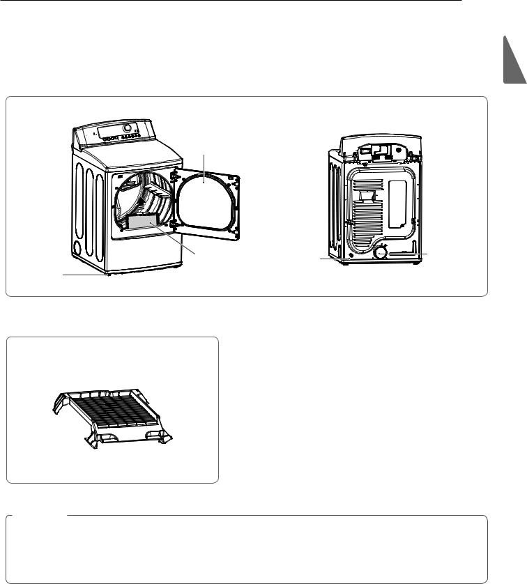
Parts
Control panel 

Reversible door
Terminal block access panel (Electric models)


 Power cord
location (Gas models)
Lint filter |
Gas connection |
Exhaust duct |
|
location |
outlet |
Leveling feet |
|
|
(Gas models) |
|
Accessories
*ODMVEFE BDDFTTPSJFT
%SZJOH SBDL
 NOTE
NOTE
t $POUBDU -( $VTUPNFS 4FSWJDF BU JO $BOBEB JG BOZ BDDFTTPSJFT BSF NJTTJOH t 'PS ZPVS TBGFUZ BOE GPS FYUFOEFE QSPEVDU MJGF VTF POMZ BVUIPSJ[FE DPNQPOFOUT 5IF NBOVGBDUVSFS JT OPU SFTQPOTJCMF GPS QSPEVDU malfunction or accidents caused by the use of separately purchased unauthorized components or parts. t5IF JNBHFT JO UIJT PXOFST NBOVBM NBZ CF EJGGFSFOU GSPN UIF BDUVBM DPNQPOFOUT BOE BDDFTTPSJFT BOE BSF TVCKFDU UP DIBOHF CZ UIF manufacturer without prior notice for product improvement purposes.
ENGLISH

10 INTRODUCING YOUR DRYER
Control panel features
Following are instructions for starting and using your new dryer. Please refer to specific sections of this manual for more detailed information.
WWARNING
To reduce the risk of fire, electric shock, or injury to persons, read this entire manual, including the Important Safety Instructions, before operating this dryer.
A E
A108&3 0/ 0'' #6550/
Press to turn the dryer ON. Press again to turn the dryer OFF.
 NOTE
NOTE
Pressing the ON/OFF button during a cycle will cancel that cycle and any load settings will be lost.
B$:$-& 4&-&$503 ,/0#
Turn this knob to select the desired cycle. Once the desired cycle has been selected, the standard presets will be shown in the display. On MANUAL DRY cycles, these settings can be adjusted using the cycle setting buttons anytime before starting the cycle.
C45"35 1"64& #6550/
Press this button to START the selected cycle. If the dryer is running, use this button to PAUSE the cycle without losing the current settings.
 NOTE
NOTE
If you do not press the START/PAUSE button to resume a cycle within 4 minutes, the dryer turns off automatically.
D.03&5*.& -&445*.& #6550/4
To adjust the drying time, use these buttons with MANUAL DRY, TIME DRY, and STEAM FRESH™ cycles, as well as the REDUCE STATIC and EASY IRON options. Press the MORE TIME button to increase the selected manual cycle time by a minute; press LESS TIME to decrease the cycle time by a minute.
F
B
C
H G D
E$:$-& 4&55*/( #6550/4
Use these buttons to select the desired cycle settings for the selected cycle. The current settings are shown in the display. Press the button for that option to view and select other settings.
F5*.& "/% 45"564 %*41-":
The display shows the settings, estimated time remaining, options, and status messages for your dryer.
G015*0/ #6550/4
The OPTION buttons allow you to select additional cycle options. Certain buttons also allow you to activate special functions by pressing and holding the
CVUUPO GPS TFDPOET
H45&". '6/$5*0/4
LG’s steam technology allows you to inject fabrics with a swirling jet of hot steam to refresh clothes, reduce static, and make ironing easier. Simply select the STEAM FRESH™ cycle, or you can add a STEAM option to selected cycles.
INTRODUCING YOUR DRYER 11
Display
The display shows the settings, estimated time remaining, options, and status messages for your dryer. When the dryer is turned on, the light in the display will illuminate.
B G C A
E
D
F
ENGLISH
A&45*."5&% 5*.& 3&."*/*/(
When the START/PAUSE button is pressed, the dryer will display the estimated (SENSOR DRY) or set time (TIME DRY) remaining, and begin tumbling.
 NOTE
NOTE
The cycle time on SENSOR DRY cycles may fluctuate as the dryer recalculates drying time for optimal results.
B$:$-& $0.1-&5*0/ */%*$"5038*5) $)&$, '*-5&3 3&.*/%&3
This portion of the display shows which stage of the
ESZJOH DZDMF JT DVSSFOUMZ VOEFSXBZ $)&$, '*-5&3
%3:*/( $00-*/( PS 83*/,-& $"3&
C$)*-% -0$, */%*$"503
8IFO $)*-% -0$, JT TFU UIF $)*-% -0$, JOEJDBUPS XJMM appear and all buttons are disabled except the POWER button. This prevents children from changing settings while the dryer is operating.
D"%% 8"5&3 */%*$"503
E$)&$, '*-5&3 3&.*/%&3
5IF EJTQMBZ XJMM TIPX $)&$, '*-5&3 XIFO UIF ESZFS JT turned on as a reminder to check the filter. It turns off when the START/PAUSE button is pressed.
F$6450. 130(3".
If you have a special combination of settings that you use frequently, you can save these settings as a CUSTOM PROGRAM.
G'-08 4&/4& %6$5 #-0$,"(& 4&/4*/( 4:45&. */%*$"503
The FLOW SENSE™ duct blockage sensing system detects and alerts you to blockages in the ductwork that reduce exhaust flow from the dryer. This improves operating efficiency and helps minimize service calls, saving your money.
If the steam feeder is low on water, this error may be displayed. Fill the feeder and restart the cycle.

12 INSTALLATION INSTRUCTIONS
INSTALLATION INSTRUCTIONS
Preview installation order
Checking and choosing |
Leveling the dryer |
the proper location |
|
Connecting Gas Dryers |
Connecting Electric Dryers |
(Gas Dryer Type) |
(Electric Dryer Type) |
Press and hold |
|
Installation test |
Test run |
(Refer to page 27.) |
|
Venting the Dryer
120V 240V
Plugging in the power cord and grounding
INSTALLATION INSTRUCTIONS 13
Installation location requirements
WWARNING
3FBE BMM JOTUBMMBUJPO JOTUSVDUJPOT DPNQMFUFMZ CFGPSF JOTUBMMJOH BOE PQFSBUJOH ZPVS ESZFS It is important that you review this entire manual before installing and using your dryer. Detailed instructions concerning electrical connections, gas connections, and exhaust requirements are provided on the following pages.
t " MPDBUJPO UIBU BMMPXT GPS QSPQFS FYIBVTU JOTUBMMBUJPO " HBT ESZFS |
t " TUVSEZ GMPPS UP TVQQPSU UIF UPUBM ESZFS XFJHIU PG MCT |
must be exhausted to the outdoors. |
kg). The combined weight of a companion appliance should also |
See 7FOUJOH UIF ESZFS 1 |
be considered. |
t " HSPVOEFE FMFDUSJDBM PVUMFU MPDBUFE XJUIJO GU DN PG FJUIFS |
t No other fuel-burning appliance can be installed in the same |
side of the dryer. See $POOFDUJOH FMFDUSJD ESZFST 1 |
closet as a dryer. |
%P OPU PQFSBUF ZPVS ESZFS BU UFNQFSBUVSFT CFMPX ¡' ¡$ "U MPXFS UFNQFSBUVSFT UIF ESZFS NJHIU OPU TIVU PGG BU UIF FOE PG BO BVUPNBUJD cycle. This can result in longer drying times. The dryer must not be installed or stored in an area where it will be exposed to water and/or weather. Check code requirements. Some codes limit, or do not permit, installation of the dryer in garages, closets, mobile homes or sleeping quarters. Contact your local building inspector.
 NOTE
NOTE
t " MFWFM GMPPS XJUI B NBYJNVN TMPQF PG JODI DN VOEFS FOUJSF ESZFS *G TMPQF JT HSFBUFS UIBO JODI DN JOTUBMM UIF &YUFOEFE %SZFS
'FFU ,JU $MPUIFT NBZ OPU UVNCMF QSPQFSMZ BOE BVUPNBUJD TFOTPS DZDMFT NBZ OPU PQFSBUF DPSSFDUMZ JG ESZFS JT OPU MFWFM t 'PS B HBSBHF JOTUBMMBUJPO ZPV XJMM OFFE UP QMBDF UIF ESZFS BU MFBTU JODIFT DN BCPWF UIF GMPPS *G VTJOH B QFEFTUBM ZPV XJMM OFFE JODIFT DN UP UIF CPUUPN PG UIF ESZFS
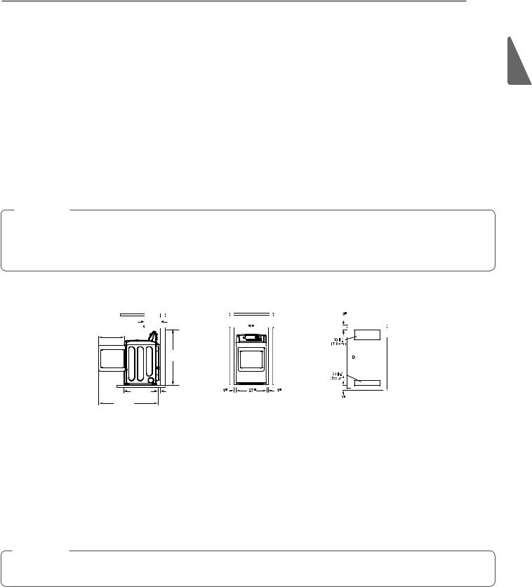
Clearances
|
14" max.* |
|
21 1⁄4" |
(35.6 cm) |
|
|
|
|
(54 cm) |
|
|
|
|
45 7⁄16" |
|
|
(115.3 cm) |
|
28 15⁄16" |
5"** |
50 1 |
(73.4 cm) |
(12.7 cm) |
" |
|
|
|
⁄4 |
|
(127.5 cm)
(2.54 cm) |
(66.6 cm) |
(2.54 cm) |
(7.6 cm)
Closet Door Vent (7.6 cm) Requirements
INSTALLATION SPACING FOR RECESSED AREA OR CLOSET INSTALLATION
The following spacing dimensions are recommended for this dryer. This dryer has been tested for spacing of 0 inches (0 cm) clearance on the sides and rear. Recommended spacing should be considered for the following reasons:
t "EEJUJPOBM TQBDJOH TIPVME CF DPOTJEFSFE GPS FBTF PG JOTUBMMBUJPO |
t "EEJUJPOBM TQBDJOH TIPVME CF DPOTJEFSFE PO BMM TJEFT PG UIF ESZFS |
and servicing. |
to reduce noise transfer. |
t "EEJUJPOBM DMFBSBODFT NJHIU CF SFRVJSFE GPS XBMM EPPS BOE GMPPS |
For closet installation, with a door, minimum ventilation openings |
moldings. |
in the top and bottom of the door are required. Louvered doors |
|
with equivalent ventilation openings are acceptable. |
|
t $PNQBOJPO BQQMJBODF TQBDJOH TIPVME BMTP CF DPOTJEFSFE |
 NOTE
NOTE
ENGLISH
There should be at least a little space around the dryer (or any other appliance) to eliminate the transfer of vibration from one to the other. Too much vibration, it could cause them to make noise or touch each other causing paint damage and making even more noise.

14 INSTALLATION INSTRUCTIONS
Clearances (cont.)
RECOMMENDED INSTALLATION SPACING FOR CABINET INSTALLATION
t For cabinet installation with a door, minimum ventilation openings in the top of the cabinet are required.
*Required spacing
**For side or bottom venting,
JODIFT DN TQBDJOH JT BMMPXFE
7"* (17.8 cm) |
7"* (17.8 cm) |
|
5"* |
28 |
1"* |
(12.7 cm) (73.4 cm) (2.5 cm) |
||
1" |
29/32" |
1" |
(2.54 cm) (68.6 cm) |
(2.54 cm) |
Leveling the dryer
WWARNING
t5P SFEVDF UIF SJTL PG JOKVSZ UP QFSTPOT BEIFSF UP BMM JOEVTUSZ SFDPNNFOEFE TBGFUZ QSPDFEVSFT JODMVEJOH UIF VTF PG MPOH TMFFWFE HMPWFT BOE TBGFUZ HMBTTFT Failure to follow this warning can cause serious injury or death.
t5IF BQQMJBODFT BSF IFBWZ 5XP PS NPSF QFPQMF BSF SFRVJSFE XIFO JOTUBMMJOH UIF ESZFS Failure to follow this warning can cause serious injury or death.
To ensure that the dryer provides optimal drying performance, it must be level. To minimize vibration, noise, and unwanted movement, the floor must be a perfectly level, solid surface.
 NOTE
NOTE
Adjust the leveling feet only as far as necessary to level the dryer. Extending the leveling feet more than necessary can cause the dryer to vibrate.
1PTJUJPO UIF ESZFS JO UIF GJOBM MPDBUJPO 1MBDF B MFWFM BDSPTT UIF top of the dryer.
Level |
t "MM GPVS MFWFMJOH GFFU NVTU SFTU TPMJEMZ PO UIF GMPPS (FOUMZ QVTI on the top corners of the dryer to make sure that the dryer does not rock from corner to corner.
If you are installing the dryer on the optional pedestal, you must use the leveling feet on the pedestal to level the dryer. The dryer leveling feet should be fully retracted.
6TF BO BEKVTUBCMF XSFODI UP UVSO UIF MFWFMJOH GFFU 5VSO clockwise to raise the dryer or counterclockwise to lower it. Raise or lower the leveling feet until dryer is level from side to side and front to back.
Make sure that all 4 leveling feet are in firm contact with the floor.
Leveling Feet

INSTALLATION INSTRUCTIONS 15
Reversing the door
WWARNING
tTo avoid damage to the dryer or the door, support the door with a stool or box that fits under the door, or have an assistant support the weight of the door.
tAvoid dropping the door to avoid damage to the door or the floor.
THE DRYER DOOR IS VERY LARGE AND HEAVY. Failure to follow the instructions below can result in damage to the dryer, property damage or injury to persons.
1.Open the door and remove the two plastic hole caps on the catch side by gently prying up with a flat blade screwdriver. Save these for step 6.
Hole cap
2.While supporting the door, remove the 4 screws, two from each hinge. Set the door aside face down on a protected surface to prevent damage to the door or the work surface.
Hinge Screw
3.With the door on a protected surface, remove the 16 screws on each side of the door and lift off the inner door frame using a flat blade screwdriver. Remove the latch hook and blank and move them to the opposite side.
inner door frame
latch hook
4.Remove the 4 screws securing the hinges to the door frame. Remove the two plastic cover caps. Reinstall the hinges and cover caps on the opposite sides from which they were removed.
Hinge assembly
Cover cap
5.With the hinges and cover caps in the new locations, remount the inner door frame onto the outer door frame with the screws removed in step 3 above.
6. Reinstall the door with the screws from step 1,2.
6.Test the swing of the door to make sure the hinges and latch are properly aligned and that the door closes and latches correctly.
ENGLISH
Swing Door
16 INSTALLATION INSTRUCTIONS
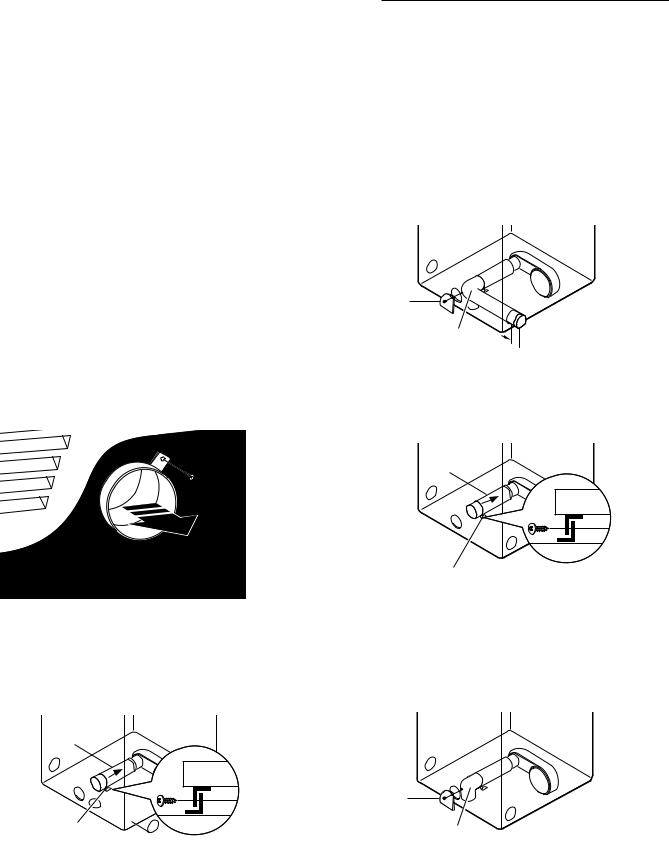
Installing the side vent kit
WWARNING
t 6TF B IFBWZ NFUBM WFOU
t %P OPU VTF QMBTUJD PS UIJO GPJM EVDU
t $MFBO PME EVDUT CFGPSF JOTUBMMJOH UIJT ESZFS
t5P SFEVDF UIF SJTL PG JOKVSZ UP QFSTPOT BEIFSF UP BMM JOEVTUSZ SFDPNNFOEFE TBGFUZ QSPDFEVSFT JODMVEJOH UIF VTF PG MPOH TMFFWFE HMPWFT BOE TBGFUZ HMBTTFT
t 'BJMVSF UP GPMMPX BMM PG UIF TBGFUZ XBSOJOHT JO UIJT NBOVBM DPVME result in property damage, injury to persons, or death.
Your new dryer is shipped to vent to the rear.
It can also be configured to vent to the bottom or side (right-side venting is not available on gas models).
An adapter kit, part number &&- #, may be purchased from your LG retailer. This kit contains the necessary duct components to change the dryer vent location.
3FNPWF UIF SFBS FYIBVTU EVDU SFUBJOJOH TDSFX 1VMM PVU UIF exhaust duct.
Retaining |
Screw |
Rear
Exhaust Duct
OPTION 1: SIDE VENTING
1SFTT UIF UBCT PO UIF LOPDLPVU BOE DBSFGVMMZ SFNPWF UIF knockout for the desired vent opening (right-side venting is not available on gas models). Press the adapter duct onto the blower housing and secure to the base of the dryer as shown.
Adapter
Duct
#SBDLFU 
 ,OPDLPVU
1SFBTTFNCMF B JODIFT DN FMCPX UP UIF OFYU JODIFT
DN EVDU TFDUJPO BOE TFDVSF BMM KPJOUT XJUI EVDU UBQF #F sure that the male end of the elbow faces AWAY from the dryer. Insert the elbow/duct assembly through the side opening and press it onto the adapter duct. Secure in place with duct tape.
#F TVSF UIBU UIF NBMF FOE PG UIF EVDU QSPUSVEFT JODIFT cm) to connect the remaining ductwork.
Attach cover plate to the back of the dryer with included screw.
Cover
Plate
Elbow
 11/2" (3.8 cm)
OPTION 2: BOTTOM VENTING
1SFTT UIF BEBQUFS EVDU POUP UIF CMPXFS IPVTJOH BOE TFDVSF UP the base of the dryer as shown.
Adapter
Duct
#SBDLFU
*OTFSU UIF JODIFT DN FMCPX UISPVHI UIF SFBS PQFOJOH BOE QSFTT JU POUP UIF BEBQUFS EVDU #F TVSF UIBU UIF NBMF FOE PG the elbow faces down through hole in the bottom of the dryer. Secure in place with duct tape.
Attach the cover plate to the back of the dryer with included screw.
Cover
Plate
Elbow

INSTALLATION INSTRUCTIONS 17
Venting the dryer
WWARNING
To reduce the risk of fire, electric shock, or injury to persons when using this appliance, follow basic precautions, including the following:
t%P OPU DSVTI PS DPMMBQTF EVDUXPSL Failure to follow these instructions can result in fire or death.
t%P OPU BMMPX EVDUXPSL UP SFTU PO PS DPOUBDU TIBSQ PCKFDUT
Failure to follow these instructions can result in fire or death.
t*G DPOOFDUJOH UP FYJTUJOH EVDUXPSL NBLF TVSF JU JT TVJUBCMF BOE DMFBO CFGPSF JOTUBMMJOH UIF ESZFS Failure to follow these instructions can result in fire or death.
t7FOUJOH NVTU DPOGPSN UP MPDBM CVJMEJOH DPEFT Failure to follow these instructions can result in fire or death.
t (BT ESZFST .645 FYIBVTU UP UIF PVUEPPST
Failure to follow these instructions can result in fire or death.
t6TF POMZ JODI DN SJHJE PS GMFYJCMF NFUBM EVDUXPSL JOTJEF UIF ESZFS DBCJOFU BOE GPS WFOUJOH PVUTJEF Failure to follow these instructions can result in fire or death.
t5P SFEVDF UIF SJTL PG GJSF DPNCVTUJPO PS BDDVNVMBUJPO PG
DPNCVTUJCMF HBTFT %0 /05 FYIBVTU ESZFS BJS JOUP BO FODMPTFE BOE VOWFOUJMBUFE BSFB TVDI BT BO BUUJD XBMM DFJMJOH DSBXM TQBDF DIJNOFZ HBT WFOU PS DPODFBMFE TQBDF PG B CVJMEJOH
Failure to follow these instructions can result in fire or death.
t5P SFEVDF UIF SJTL PG GJSF %0 /05 FYIBVTU UIF ESZFS XJUI
QMBTUJD PS UIJO GPJM EVDUJOH
Failure to follow these instructions can result in fire or death.
t5IF FYIBVTU EVDU NVTU CF JODIFT DN JO EJBNFUFS XJUI
OP PCTUSVDUJPOT 5IF FYIBVTU EVDU TIPVME CF LFQU BT TIPSU BT QPTTJCMF .BLF TVSF UP DMFBO BOZ PME EVDUT CFGPSF JOTUBMMJOH ZPVS OFX ESZFS Failure to follow these instructions can result in fire or death.
t3JHJE PS TFNJSJHJE NFUBM EVDUJOH JT SFDPNNFOEFE GPS VTF
CFUXFFO UIF ESZFS BOE UIF XBMM *O TQFDJBM JOTUBMMBUJPOT XIFO JU JT JNQPTTJCMF UP NBLF B DPOOFDUJPO XJUI UIF BCPWF SFDPNNFOEBUJPOT B 6- MJTUFE GMFYJCMF NFUBM USBOTJUJPO EVDU NBZ CF VTFE CFUXFFO UIF ESZFS BOE XBMM DPOOFDUJPO POMZ 5IF VTF PG UIJT EVDUJOH XJMM BGGFDU ESZJOH UJNF Failure to follow these instructions can result in fire or death.
t %0 /05 VTF TIFFU NFUBM TDSFXT PS PUIFS GBTUFOFST XIJDI
FYUFOE JOUP UIF EVDU UIBU DPVME DBUDI MJOU BOE SFEVDF UIF FGGJDJFODZ PG UIF FYIBVTU TZTUFN 4FDVSF BMM KPJOUT XJUI EVDU tape. Failure to follow these instructions can result in fire or death.
t5P NBYJNJ[F PQFSBUJOH SFTVMUT QMFBTF PCTFSWF UIF EVDU MFOHUI MJNJUBUJPOT OPUFE JO UIF DIBSU OFYU QBHF Failure to follow these instructions can result in fire or death.
t%VDUXPSL JT OPU QSPWJEFE XJUI UIF ESZFS :PV TIPVME PCUBJO
UIF OFDFTTBSZ EVDUXPSL MPDBMMZ 5IF FOE DBQ TIPVME IBWF IJOHFE EBNQFST UP QSFWFOU CBDLESBGU XIFO UIF ESZFS JT OPU JO use. Failure to follow these instructions can result in fire or death.
t5IF5PUBM MFOHUI PG GMFYJCMF NFUBM EVDU TIBMM OPU FYDFFE GU
N
t*O $BOBEB UIBU POMZ UIPTF GPJM UZQF GMFYJCMF EVDUT JG BOZ
TQFDJGJDBMMZ JEFOUJGJFE GPS VTF XJUI UIF BQQMJBODF CZ UIF NBOVGBDUVSFS TIBMM CF VTFE In the United States, that only those foil-type flexible ducts, if any, specifically identified for use with the appliance by the manufacturer and that comply with the
0VUMJOF GPS $MPUIFT %SZFS5SBOTJUJPO %VDU 4VCKFDU " TIBMM CF used.
ENGLISH

18 INSTALLATION INSTRUCTIONS
Venting the dryer (cont.)
Ductwork |
|
|
|
/6.#&3 0' ¡ |
."9*.6. -&/(5) 0' |
8"-- $"1 5:1& |
ű*/$) %*".&5&3 3*(*% |
|
|
&-#084 |
.&5"- %6$5 |
|
|
|
Recommended |
0 |
GU N |
|
|
GU N |
4" |
|
GU N |
(10.2 cm) |
||
|
|
GU N |
4" |
4 |
GU N |
(10.2 cm) |
||
Use only for short |
0 |
GU N |
run installations |
|
GU N |
|
||
|
|
GU N |
21/2" |
|
GU N |
(6.35 cm) |
|
|
|
4 |
GU N |
 NOTE
NOTE
%FEVDU GU N GPS FBDI BEEJUJPOBM FMCPX *U JT OPU SFDPNNFOEFE
UP VTF NPSF UIBO GPVS ¡ FMCPXT
ROUTING AND CONNECTING DUCTWORK
 NOTE
NOTE
$033&$57&/5*/( |
*/$033&$57&/5*/( |
Follow the guidelines below to maximize drying performance and reduce lint buildup and condensation in the ductwork.
Ductwork and fittings are NOT included and must be purchased separately.
t 6TF JODI DN EJBNFUFS SJHJE PS TFNJSJHJE NFUBM EVDUXPSL t5IF FYIBVTU EVDU SVO TIPVME CF BT TIPSU BT QPTTJCMF t 6TF BT GFX FMCPX KPJOUT BT QPTTJCMF t5IF NBMF FOE PG FBDI TFDUJPO PG FYIBVTU EVDU NVTU QPJOU BXBZ GSPN the dryer.
t 6TF EVDU UBQF PO BMM EVDU KPJOUT t *OTVMBUF EVDUXPSL UIBU SVOT UISPVHI VOIFBUFE BSFBT JO PSEFS UP reduce condensation and lint buildup on duct surfaces.
t 'BJMVSF UP FYIBVTU UIF ESZFS DPSSFDUMZ XJMM WPJE UIF ESZFST XBSSBOUZ

INSTALLATION INSTRUCTIONS 19
Connecting gas dryers
WWARNING
To reduce the risk of fire, electric shock, or injury to persons when using this appliance, follow basic precautions, including the following:
t(BT TVQQMZ SFRVJSFNFOUT
"T TIJQQFE GSPN UIF GBDUPSZ UIJT ESZFS JT DPOGJHVSFE GPS VTF XJUI OBUVSBM HBT *U DBO CF DPOWFSUFE GPS VTF XJUI -1 -JRVFGJFE 1SPQBOF HBT (BT QSFTTVSF NVTU OPU FYDFFE JODIFT PG XBUFS DPMVNO
t" RVBMJGJFE TFSWJDF PS HBT DPNQBOZ UFDIOJDJBO NVTU DPOOFDU
UIF ESZFS UP UIF HBT TFSWJDF
Failure to do so can result in fire, explosion, or death.
t*TPMBUF UIF ESZFS GSPN UIF HBT TVQQMZ TZTUFN CZ DMPTJOH JUT
JOEJWJEVBM NBOVBM TIVUPGG WBMWF EVSJOH BOZ QSFTTVSF UFTUJOH PG UIF HBT TVQQMZ Failure to do so can result in fire, explosion, or death.
t4VQQMZ MJOF SFRVJSFNFOUT
:PVS MBVOESZ SPPN NVTU IBWF B SJHJE HBT TVQQMZ MJOF UP ZPVS ESZFS *O UIF 6OJUFE 4UBUFT BO JOEJWJEVBM NBOVBM TIVUPGG WBMWF
.645 CF JOTUBMMFE XJUIJO BU MFBTU GU N PG UIF ESZFS JO BDDPSEBODF XJUI UIF /BUJPOBM 'VFM (BT $PEF "/4* ; PS $BOBEJBO HBT JOTUBMMBUJPO DPEF $4" # " 1cľ JODI /15 QJQF QMVH NVTU CF JOTUBMMFE Failure to do so can result in fire, explosion, or death
t*G VTJOH B SJHJE QJQF UIF SJHJE QJQF TIPVME CF JODI *14
*G BDDFQUBCMF VOEFS MPDBM DPEFT BOE PSEJOBODFT BOE XIFO BDDFQUBCMF UP ZPVS HBT TVQQMJFS 3cľ JODI BQQSPWFE UVCJOH NBZ CF VTFE XIFSF MFOHUIT BSF MFTT UIBO GU N -BSHFS UVCJOH TIPVME CF VTFE GPS MFOHUIT JO FYDFTT PG GU N
Failure to do so can result in fire, explosion, or death.
Electrical requirements for gas models only
WWARNING
t$POOFDU UIF ESZFS UP UIF UZQF PG HBT TIPXO PO UIF OBNFQMBUF
Failure to do so can result in fire, explosion, or death.
t5P QSFWFOU DPOUBNJOBUJPO PG UIF HBT WBMWF QVSHF UIF HBT
TVQQMZ PG BJS BOE TFEJNFOU CFGPSF DPOOFDUJOH UIF HBT TVQQMZ UP UIF ESZFS #FGPSF UJHIUFOJOH UIF DPOOFDUJPO CFUXFFO UIF HBT TVQQMZ BOE UIF ESZFS QVSHF SFNBJOJOH BJS VOUJM UIF PEPS PG HBT JT EFUFDUFE Failure to do so can result in fire, explosion, or death.
t%0 /05 VTF BO PQFO GMBNF UP JOTQFDU GPS HBT MFBLT 6TF B OPODPSSPTJWF MFBL EFUFDUJPO GMVJE Failure to do so can result in fire, explosion, or death.
t6TF POMZ B OFX "(" PS $4" DFSUJGJFE HBT TVQQMZ MJOF XJUI GMFYJCMF TUBJOMFTT TUFFM DPOOFDUPST Failure to do so can result in fire, explosion, or death.
t4FDVSFMZ UJHIUFO BMM HBT DPOOFDUJPOT Failure to do so can result in fire, explosion, or death.
t%0 /05 BUUFNQU BOZ EJTBTTFNCMZ PG UIF ESZFS BOZ
EJTBTTFNCMZ SFRVJSFT UIF BUUFOUJPO BOE UPPMT PG BO BVUIPSJ[FE BOE RVBMJGJFE TFSWJDF QFSTPO PS DPNQBOZ Failure to do so can result in fire, explosion, or death.
t6TF B QJQF KPJOU DPNQPVOE UIBU JT JOTPMVCMF JO -JRVFGJFE 1FUSPMFVN -1 HBT PO BMM QJQF UISFBET Failure to do so can result in fire, explosion, or death.
To reduce the risk of fire, electric shock, or injury to persons when using this appliance, follow basic precautions, including the following:
t%P OPU VOEFS BOZ DJSDVNTUBODFT DVU PS SFNPWF UIF UIJSE |
t5IJT ESZFS NVTU CF QMVHHFE JOUP B )[ 7"$ HSPVOEFE |
HSPVOE QSPOH GSPN UIF QPXFS DPSE Failure to follow this |
PVUMFU QSPUFDUFE CZ B BNQFSF GVTF PS DJSDVJU CSFBLFS Failure |
warning can result in fire, explosion, or death. |
to follow this warning can result in fire, explosion, or death. |
t'PS QFSTPOBM TBGFUZ UIJT ESZFS NVTU CF QSPQFSMZ HSPVOEFE |
t8IFSF B TUBOEBSE QSPOH XBMM PVUMFU JT FODPVOUFSFE JU JT ZPVS |
Failure to follow this warning can result in fire, explosion, or death. |
QFSTPOBM SFTQPOTJCJMJUZ BOE PCMJHBUJPO UP IBWF JU SFQMBDFE XJUI |
t5IF QPXFS DPSE PG UIJT ESZFS JT FRVJQQFE XJUI B QSPOH |
B QSPQFSMZ HSPVOEFE QSPOH XBMM PVUMFU Failure to follow this |
HSPVOEJOH QMVH XIJDI NBUFT XJUI B TUBOEBSE QSPOH |
warning can result in fire, explosion, or death. |
HSPVOEJOH XBMM PVUMFU UP NJOJNJ[F UIF QPTTJCJMJUZ PG FMFDUSJD |
|
TIPDL IB[BSE GSPN UIJT BQQMJBODF Failure to follow this warning |
|
can result in fire, explosion, or death. |
|
ENGLISH
20 INSTALLATION INSTRUCTIONS
Connecting gas dryers (cont.)
WWARNING
To reduce the risk of fire, electric shock, or injury to persons when using this appliance, follow basic precautions, including the following:
t *OTUBMMBUJPO BOE TFSWJDF NVTU CF QFSGPSNFE CZ B RVBMJGJFE JOTUBMMFS TFSWJDF BHFODZ PS UIF HBT TVQQMJFS Failure to do so can result in fire, explosion, or death.
t 6TF POMZ B OFX TUBJOMFTT TUFFM GMFYJCMF DPOOFDUPS BOE B OFX "(" DFSUJGJFE DPOOFDUPS Failure to do so can result in fire, explosion, or death.
t " HBT TIVUPGG WBMWF NVTU CF JOTUBMMFE XJUIJO GU N PG the dryer. Failure to do so can result in fire, explosion, or death.
t 5IF ESZFS JT DPOGJHVSFE GPS /BUVSBM (BT XIFO TIJQQFE GSPN
UIF GBDUPSZ .BLF TVSF UIBU UIF ESZFS JT FRVJQQFE XJUI UIF DPSSFDU CVSOFS PSJGJDF GPS UIF UZQF PG HBT CFJOH VTFE /BUVSBM (BT PS -JRVFGJFE 1FUSPMFVN Failure to do so can result in fire, explosion, or death.
t *G OFDFTTBSZ UIF DPSSFDU PSJGJDF GPS UIF -1 PSJGJDF LJU PSEFS
QBSU OVNCFS &&- % TIPVME CF JOTUBMMFE CZ B RVBMJGJFE UFDIOJDJBO BOE UIF DIBOHF TIPVME CF OPUFE PO UIF dryer. Failure to do so can result in fire, explosion, or death.
t "MM DPOOFDUJPOT NVTU CF JO BDDPSEBODF XJUI MPDBM DPEFT BOE SFHVMBUJPOT. Failure to do so can result in fire, explosion, or death.
t (BT ESZFST .645 FYIBVTU UP UIF PVUEPPST Failure to do so can result in fire, explosion, or death.
Connecting the gas supply
.BLF TVSF UIBU UIF HBT TVQQMZ UP UIF MBVOESZ SPPN JT UVSOFE
OFF. Confirm that the type of gas available in your laundry room is appropriate for the dryer. The dryer is prepared for Natural Gas with a ⁄8 - inch NPT gas connection.
3FNPWF UIF TIJQQJOH DBQ GSPN UIF HBT DPOOFDUJPO BU UIF CBDL
PG UIF ESZFS #F DBSFGVM OPU UP EBNBHF UIF UISFBET PG UIF HBT connector when removing the shipping cap.
$POOFDU UIF ESZFS UP ZPVS MBVOESZ SPPNT HBT TVQQMZ VTJOH B new flexible stainless steel connector with a ⁄8 - inch NPT fitting.
4.Securely tighten all connections between the dryer and your laundry room’s gas supply. Turn on your laundry room’s gas supply and check all pipe connections (both internal and external) for gas leaks with a noncorrosive leak-detection fluid.
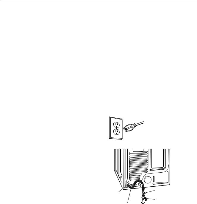
Electrical connection
Plug dryer into a 7"$)[ HSPVOEFE QSPOH PVUMFU
w/15 (BT |
w/15 1JQF |
Plug |
|
Connection |
Gas Supply |
|
|
AGA/CSA-Certified |
Shutoff Valve |
Stainless Steel Flexible |
|
Connector |
|
High-altitude installations
5IF #56 SBUJOH PG UIJT ESZFS JT "(" DFSUJGJFE GPS FMFWBUJPOT CFMPXGFFU
*G ZPVS HBT ESZFS JT CFJOH JOTUBMMFE BU BO FMFWBUJPO BCPWF feet, it must be derated by a qualified technician or gas supplier.
INSTALLATION INSTRUCTIONS 21
Connecting electric dryers
WWARNING
To help prevent fire, electric shock, serious injury, or death, the wiring and grounding must conform to the latest edition of the
/BUJPOBM &MFDUSJDBM $PEF "/4* /'1" BOE BMM BQQMJDBCMF MPDBM regulations. Please contact a qualified electrician to check your home’s wiring and fuses to ensure that your home has adequate electrical power to operate the dryer.
Electrical requirements for electric models only
WWARNING
To reduce the risk of fire, electric shock, or injury to persons when using this appliance, follow basic precautions, including the following:
t 5IJT ESZFS NVTU CF DPOOFDUFE UP B HSPVOEFE NFUBM
QFSNBOFOU XJSJOH TZTUFN PS BO FRVJQNFOU HSPVOEJOH DPOEVDUPS NVTU CF SVO XJUI UIF DJSDVJU DPOEVDUPST BOE DPOOFDUFE UP UIF FRVJQNFOU HSPVOEJOH UFSNJOBM PS MFBE PO the dryer. Failure to do so can result in fire, explosion, or death.
t 5IF ESZFS IBT JUT PXO UFSNJOBM CMPDL UIBU NVTU CF DPOOFDUFE
UP B TFQBSBUF 7"$ )FSU[ TJOHMF QIBTF DJSDVJU GVTFE BU BNQFSFT UIF DJSDVJU NVTU CF GVTFE PO CPUI TJEFT PG UIF MJOF &-&$53*$"- 4&37*$& '035)& %3:&3 4)06-% #& 0' 5)& ."9*.6. 3"5&70-5"(& -*45&% 0/5)& /".&1-"5& %0 /05 $0//&$5 %3:&350 03 70-5 $*3$6*5 Failure to follow these instructions can result in fire, explosion, or death.
t*G CSBODI DJSDVJU UP ESZFS JT GU N PS MFTT JO MFOHUI
VTF 6- 6OEFSXSJUFST -BCPSBUPSJFT MJTUFE /P "8( XJSF DPQQFS XJSF POMZ PS BT SFRVJSFE CZ MPDBM DPEFT *G PWFSGU N VTF 6- MJTUFE /P "8( XJSF DPQQFS XJSF POMZ PS BT SFRVJSFE CZ MPDBM DPEFT "MMPX TVGGJDJFOU TMBDL JO XJSJOH TP ESZFS DBO CF NPWFE GSPN JUT OPSNBM MPDBUJPO XIFO OFDFTTBSZ Failure to do so can result in fire, explosion, or death.
t 5IF QPXFS DPSE QJHUBJM DPOOFDUJPO CFUXFFO XBMM SFDFQUBDMF
BOE ESZFS UFSNJOBM CMPDL *4 /05 TVQQMJFE XJUI ESZFS 5ZQF PG QJHUBJM BOE HBVHF PG XJSF NVTU DPOGPSN UP MPDBM DPEFT BOE XJUI JOTUSVDUJPOT PO UIF GPMMPXJOH QBHFT Failure to follow these instructions can result in fire, explosion, or death.
t" XJSF DPOOFDUJPO JT SFRVJSFE GPS BMM NPCJMF BOE
NBOVGBDUVSFE IPNF JOTUBMMBUJPOT BT XFMM BT BMM OFX DPOTUSVDUJPO BGUFS +BOVBSZ " XJSF DPOOFDUJPO NVTU CF VTFE XIFSF MPDBM DPEFT EP OPU QFSNJU HSPVOEJOH UISPVHI UIF OFVUSBM XJSF Failure to do so can result in fire, explosion, or death.
WWARNING
To reduce the risk of fire, electric shock, or injury to persons when using this appliance, follow basic precautions, including the following:
t %P OPU NPEJGZ UIF QMVH BOE JOUFSOBM XJSF QSPWJEFE XJUI UIF dryer.
t5IF ESZFS TIPVME CF DPOOFDUFE UP IPMF PVUMFU
t *G JU EPFT OPU GJU UIF PVUMFU B QSPQFS PVUMFU XJMM OFFE UP CF JOTUBMMFE CZ B RVBMJGJFE FMFDUSJDJBO
WWARNING
To reduce the risk of fire, electric shock, or injury to persons when using this appliance, follow basic precautions, including the following:
t "OZ JOTUBMMBUJPO JO B NBOVGBDUVSFE PS NPCJMF IPNF NVTU
DPNQMZ XJUI UIF .BOVGBDUVSFE )PNF $POTUSVDUJPO BOE 4BGFUZ 4UBOEBSET5JUMF $'3 1BSU PS 4UBOEBSE $"/ $4" ; .) BOE MPDBM DPEFT BOE PSEJOBODFT
t" XJSF DPOOFDUJPO JT SFRVJSFE GPS BMM NPCJMF BOE
NBOVGBDUVSFE IPNF JOTUBMMBUJPOT BT XFMM BT BMM OFX DPOTUSVDUJPO BGUFS +BOVBSZ Failure to do so can result in fire, explosion, or death.
ENGLISH

22 INSTALLATION INSTRUCTIONS
Connecting electric dryers (cont.) USA only
WWARNING
t $POOFDU UIF QPXFS DPSE UP UIF UFSNJOBM CMPDL &BDI DPMPSFE
XJSF TIPVME CF DPOOFDUFE UP TBNF DPMPS TDSFX 8JSF DPMPS JOEJDBUFE PO NBOVBM JT DPOOFDUFE UP UIF TBNF DPMPS TDSFX JO CMPDL 'BJMVSF UP GPMMPX UIFTF JOTUSVDUJPOT NBZ SFTVMU JO B TIPSU PS PWFSMPBE
t (SPVOEJOH UISPVHI UIF OFVUSBM DPOEVDUPS JT QSPIJCJUFE
GPS OFX CSBODI DJSDVJU JOTUBMMBUJPOT NPCJMF IPNFTSFDSFBUJPOBM WFIJDMFT BOE BSFBT XIFSF MPDBM DPEFT QSPIJCJU HSPVOEJOH UISPVHI UIF OFVUSBM DPOEVDUPS
Four-wire connection for electric dryers:
Power cord
t " XJSF DPOOFDUJPO JT SFRVJSFE GPS BMM NPCJMF BOE NBOVGBDUVSFE IPNF JOTUBMMBUJPOT BT XFMM BT BMM OFX DPOTUSVDUJPO BGUFS +BOVBSZ
t " 6- MJTUFE TUSBJO SFMJFG JT SFRVJSFE
3FNPWF UIF UFSNJOBM CMPDL BDDFTT DPWFS PO UIF VQQFS CBDL PG the dryer. Install a UL-listed strain relief into the power cord through-hole; then thread a UL-listed, " 7 XJSF "8( NJOJNVN DPQQFS conductor power cord through the strain relief.
Terminal
 #MPDL
#MPDL
UL-Listed
Strain Relief
t 6TF B " 7 6- MJTUFE QPXFS DPSE XJUI "8( NJOJNVN DPQQFS conductor and closed loop or forked terminals with upturned ends.
5SBOTGFS UIF ESZFST HSPVOE XJSF GSPN CFIJOE UIF HSFFO HSPVOE screw to the center screw of the terminal block. Attach the two hot leads of the power cord to the outer terminal block screws. Attach the white neutral wire to the center terminal block screw. Attach the power cord ground wire to the green ground screw. 5*()5&/ "-- 4$3&84 4&$63&-:. Reinstall the terminal block access cover.
Hot |
Neutral |
Hot |
#MBDL |
(White) |
|
|
|
(Red) |
Ground
Screw
Power Cord |
Ground Wire |
UL-Listed
4-Wire Power
Cord

INSTALLATION INSTRUCTIONS 23
Connecting electric dryers (cont.) USA only
WWARNING
t $POOFDU UIF QPXFS DPSE UP UIF UFSNJOBM CMPDL &BDI DPMPSFE
XJSF TIPVME CF DPOOFDUFE UP TBNF DPMPS TDSFX 8JSF DPMPS JOEJDBUFE PO NBOVBM JT DPOOFDUFE UP UIF TBNF DPMPS TDSFX JO CMPDL 'BJMVSF UP GPMMPX UIFTF JOTUSVDUJPOT NBZ SFTVMU JO B TIPSU PS PWFSMPBE
t (SPVOEJOH UISPVHI UIF OFVUSBM DPOEVDUPS JT QSPIJCJUFE
GPS OFX CSBODI DJSDVJU JOTUBMMBUJPOT NPCJMF IPNFTSFDSFBUJPOBM WFIJDMFT BOE BSFBT XIFSF MPDBM DPEFT QSPIJCJU HSPVOEJOH UISPVHI UIF OFVUSBM DPOEVDUPS
Four-wire connection for electric dryers: Direct wire
t " XJSF DPOOFDUJPO JT SFRVJSFE GPS BMM NPCJMF BOE NBOVGBDUVSFE IPNF JOTUBMMBUJPOT BT XFMM BT BMM OFX DPOTUSVDUJPO BGUFS +BOVBSZ
t " 6- MJTUFE TUSBJO SFMJFG JT SFRVJSFE
3FNPWF JODIFT DN PG UIF PVUFS DPWFSJOH GSPN UIF XJSF 3FNPWF JODIFT PG JOTVMBUJPO GSPN UIF HSPVOE XJSF $VU PGG BQQSPYJNBUFMZ cĸ JODIFT DN GSPN UIF PUIFS UISFF XJSFT BOE TUSJQ JODI DN JOTVMBUJPO GSPN FBDI XJSF #FOE UIF ends of the three shorter wires into a hook shape.
DN
Ground Wire
DN
3FNPWF UIF UFSNJOBM CMPDL BDDFTT DPWFS PO UIF VQQFS CBDL PG the dryer. Install a UL-listed strain relief into the power cord
UISPVHI IPMF UIFO UISFBE UIF QPXFS DBCMF QSFQBSFE JO 4UFQ through the strain relief.
Terminal

 #MPDL
#MPDL
UL-Listed
Strain Relief
t 6TF 6- MJTUFE XJSF "8( NJOJNVN DPQQFS conductor cable.
t "MMPX BU MFBTU GU N MFOHUI UP BMMPX GPS SFNPWBM BOE reinstallation of the dryer.
5SBOTGFS UIF ESZFST HSPVOE XJSF GSPN CFIJOE UIF HSFFO HSPVOE screw to the center screw of the terminal block. Attach the two hot leads of the power cable to the outer terminal block screws. Attach the white neutral wire to the center terminal block screw. Attach the power cable ground wire to the green ground screw. 5*()5&/ "-- 4$3&84 4&$63&-:. Reinstall the terminal block access cover.
Hot |
Neutral |
Hot |
#MBDL |
(White) |
|
|
|
(Red) |
Ground
Screw
Power Cord |
Ground Wire |
UL-Listed
4-Wire Power
Cord
ENGLISH

24 INSTALLATION INSTRUCTIONS
Connecting electric dryers (cont.) USA only
WWARNING
t $POOFDU UIF QPXFS DPSE UP UIF UFSNJOBM CMPDL &BDI DPMPSFE
XJSF TIPVME CF DPOOFDUFE UP TBNF DPMPS TDSFX 8JSF DPMPS JOEJDBUFE PO NBOVBM JT DPOOFDUFE UP UIF TBNF DPMPS TDSFX JO CMPDL 'BJMVSF UP GPMMPX UIFTF JOTUSVDUJPOT NBZ SFTVMU JO B TIPSU PS PWFSMPBE
t (SPVOEJOH UISPVHI UIF OFVUSBM DPOEVDUPS JT QSPIJCJUFE
GPS OFX CSBODI DJSDVJU JOTUBMMBUJPOT NPCJMF IPNFTSFDSFBUJPOBM WFIJDMFT BOE BSFBT XIFSF MPDBM DPEFT QSPIJCJU HSPVOEJOH UISPVHI UIF OFVUSBM DPOEVDUPS
Three-wire connection for electric dryers:
Power cord
t " XJSF DPOOFDUJPO JT /05 QFSNJUUFE PO OFX DPOTUSVDUJPO BGUFS +BOVBSZ
t " 6- MJTUFE TUSBJO SFMJFG JT SFRVJSFE
3FNPWF UIF UFSNJOBM CMPDL BDDFTT DPWFS PO UIF VQQFS CBDL PG the dryer. Install a UL-listed strain relief into the power cord through-hole; then thread a UL-listed, " 7 XJSF "8( NJOJNVN DPQQFS conductor power cord through the strain relief.
Terminal

 #MPDL
#MPDL
UL-Listed
Strain Relief
t 6TF B " 7 6- MJTUFE QPXFS DPSE XJUI "8( NJOJNVN DPQQFS conductor and closed loop or forked terminals with upturned ends.
"UUBDI UIF UXP IPU MFBET PG UIF QPXFS DPSE UP UIF PVUFS terminal block screws. Attach the neutral wire to the center terminal block screw. Connect the external ground (if required by local codes) to the green ground screw. 5*()5&/ "-- 4$3&84 4&$63&-:. Reinstall the terminal block access cover.
Hot |
Neutral |
|
#MBDL |
(White) |
Hot |
|
|
(Red) |
Ground
Screw
Neutral
Ground
Wire
External
Ground Wire
UL-Listed
8JSF 1PXFS
Cord

INSTALLATION INSTRUCTIONS 25
Connecting electric dryers (cont.) USA only
WWARNING
t $POOFDU UIF QPXFS DPSE UP UIF UFSNJOBM CMPDL &BDI DPMPSFE
XJSF TIPVME CF DPOOFDUFE UP TBNF DPMPS TDSFX 8JSF DPMPS JOEJDBUFE PO NBOVBM JT DPOOFDUFE UP UIF TBNF DPMPS TDSFX JO CMPDL 'BJMVSF UP GPMMPX UIFTF JOTUSVDUJPOT NBZ SFTVMU JO B TIPSU PS PWFSMPBE
t (SPVOEJOH UISPVHI UIF OFVUSBM DPOEVDUPS JT QSPIJCJUFE
GPS OFX CSBODI DJSDVJU JOTUBMMBUJPOT NPCJMF IPNFTSFDSFBUJPOBM WFIJDMFT BOE BSFBT XIFSF MPDBM DPEFT QSPIJCJU HSPVOEJOH UISPVHI UIF OFVUSBM DPOEVDUPS
Three-wire connection for electric dryers: Direct wire
t " XJSF DPOOFDUJPO JT /05 QFSNJUUFE PO OFX DPOTUSVDUJPO BGUFS +BOVBSZ
t " 6- MJTUFE TUSBJO SFMJFG JT SFRVJSFE
3FNPWF cĸ JODIFT DN PG UIF PVUFS DPWFSJOH GSPN UIF XJSF
4USJQ JODI DN JOTVMBUJPO GSPN FBDI XJSF #FOE UIF FOET PG the three wires into a hook shape.
DN
3FNPWF UIF UFSNJOBM CMPDL BDDFTT DPWFS PO UIF VQQFS CBDL PG the dryer. Install a UL-listed strain relief into the power cord
UISPVHI IPMF UIFO UISFBE UIF QPXFS DBCMF QSFQBSFE JO 4UFQ through the strain relief.
Terminal

 #MPDL
#MPDL
UL-Listed
Strain Relief
t 6TF 6- MJTUFE XJSF "8( NJOJNVN DPQQFS conductor cable.
t "MMPX BU MFBTU GU N MFOHUI UP BMMPX GPS SFNPWBM BOE reinstallation of the dryer.
"UUBDI UIF UXP IPU MFBET PG UIF QPXFS DPSE UP UIF PVUFS terminal block screws. Attach the neutral wire to the center terminal block screw. Connect the external ground (if required by local codes) to the green ground screw. 5*()5&/ "-- 4$3&84 4&$63&-:. Reinstall the terminal block access cover.
Hot |
Neutral |
|
#MBDL |
(White) |
Hot |
|
|
(Red) |
Ground
Screw
Neutral
Ground
Wire
External
Ground Wire
UL-Listed
8JSF 1PXFS
Cord
ENGLISH

26 INSTALLATION INSTRUCTIONS
Special requirements for manufactured or mobile homes
Any installation in a manufactured or mobile home must comply with the Manufactured Home Construction and Safety Standards
5JUMF $'3 1BSU PS 4UBOEBSE $"/ $4" ; .) BOE local codes and ordinances. If you are uncertain whether your proposed installation will comply with these standards, please contact a service and installation professional for assistance.
t " HBT ESZFS NVTU CF QFSNBOFOUMZ BUUBDIFE UP UIF GMPPS
t5IF FMFDUSJDBM DPOOFDUJPO GPS BO FMFDUSJD ESZFS NVTU CF B XJSF connection. More detailed information concerning the electrical connection is provided in the section Connecting Electric Dryers.
t5P SFEVDF UIF SJTL PG DPNCVTUJPO BOE GJSF UIF ESZFS NVTU CF vented to the outside.
t %0 /05 WFOU UIF ESZFS VOEFS B NBOVGBDUVSFE IPNF PS NPCJMF home.
t &MFDUSJD ESZFST NBZ CF WFOUFE UP UIF PVUTJEF VTJOH UIF CBDL MFGU right, or bottom panel.
t (BT ESZFST NBZ CF WFOUFE UP UIF PVUTJEF VTJOH UIF CBDL MFGU or bottom panel. Gas dryers may not be vented to the outside using the right side panel because of the burner housing.
t5IF ESZFS FYIBVTU EVDU NVTU CF BGGJYFE TFDVSFMZ UP UIF manufactured or mobile home structure, and the exhaust duct must be made of a material that will resist fire and combustion. It is recommended that you use a rigid or flexible metal duct.
t %0 /05 DPOOFDU UIF ESZFS FYIBVTU EVDU UP BOZ PUIFS EVDU WFOU chimney, or other exhaust duct.
t .BLF TVSF UIF ESZFS IBT BEFRVBUF BDDFTT UP PVUTJEF GSFTI BJS UP ensure proper operation. The opening for outside fresh air must
CF BU MFBTU JO DN ).
t *U JT JNQPSUBOU UIBU UIF DMFBSBODF PG UIF EVDU GSPN BOZ DPNCVTUJCMF DPOTUSVDUJPO CF BU MFBTU JODIFT DN BOE XIFO venting the dryer to the outdoors, the dryer can be installed with
B DMFBSBODF PG JODI DN BU UIF TJEFT BOE CBDL PG UIF ESZFS
t 1MFBTF CF BXBSF UIBU WFOUJOH NBUFSJBMT BSF OPU TVQQMJFE XJUI the dryer. You should obtain the venting materials necessary for proper installation.
Final installation check
Once you have completed the installation of the dryer and it is in its final location, confirm proper operation with the following tests and Installation Test (Duct Check) on the following page.
Testing dryer heating
("4 .0%&-4
Close the dryer door, press the ON/OFF button to turn the dryer on, and start the dryer on a heat setting. When the dryer starts, the igniter should ignite the main burner.
 NOTE
NOTE
If all air is not purged from the gas line, the gas igniter may turn off before the main burner ignites. If this happens, the igniter will reattempt gas ignition after approximately two minutes.
&-&$53*$ .0%&-4
Close the dryer door, press the ON/OFF switch to turn the dryer on, and start the dryer on a heat setting. The exhaust air should
CF XBSN BGUFS UIF ESZFS IBT CFFO PQFSBUJOH GPS NJOVUFT
Checking airflow
Effective dryer operation requires proper airflow.
The adequacy of the airflow can be measured by evaluating the static pressure. Static pressure in the exhaust duct can be measured with a manometer, placed on the exhaust duct
BQQSPYJNBUFMZ GU DN GSPN UIF ESZFS 4UBUJD QSFTTVSF JO UIF FYIBVTU EVDU TIPVME OPU FYDFFE JODIFT
DN 5IF ESZFS TIPVME CF DIFDLFE XIJMF UIF ESZFS JT SVOOJOH with no load.
Checking levelness
Once the dryer is in its final location, recheck the dryer to be sure it is level. Make sure it is level front to back and side to side, and that all 4 leveling feet are firmly on the floor.

INSTALLATION INSTRUCTIONS 27
Installation test (Duct check)
Once you have completed the installation of the dryer, use this test to make sure the condition of the exhaust system is adequate for proper operation of the dryer. This test should be performed to alert you to any serious problems in the exhaust system of your home.
t:PVS ESZFS GFBUVSFT FLOW SENSETM, an innovative sensing system that automatically detects blockages and restrictions in dryer
EVDUXPSL ,FFQJOH EVDUXPSL DMFBO PG MJOU CVJMEVQ BOE GSFF PG restrictions allows clothes to dry faster and reduces energy use.
 NOTE
NOTE
The dryer should be cool before starting this test. If the dryer was warmed up during installation, run the AIR DRY cycle for a few minutes to reduce the interior temperature.
5P BDUJWBUF UIF JOTUBMMBUJPO UFTU
3FNPWF UIF ESZJOH SBDL BOE MJUFSBUVSF BOE UIFO DMPTF UIF door.
Do not load anything in the drum for this test, as in may affect the accuracy of the results.
4.$IFDL UIF EJTQMBZ GPS SFTVMUT
During the two minute test cycle, monitor the FLOW SENSETM display on the control panel. If no bars are displayed, when the cycle ends, the exhaust system is adequate. If the exhaust system is severely restricted, the display will show four bars. Other problems may also be shown with error codes. Refer to the next page for error code details and solutions.
|
|
|
|
|
/0 #"34 |
'063 #"34 |
|||
0, |
|
RESTRICTED |
||
Four bars indicates that the exhaust system is severely restricted. Have the system checked immediately, as performance will be poor.
&OE PG DZDMF
At the end of the test cycle,  will display. The test cycle will end and the dryer will shut off automatically after a short delay.
1SFTT BOE IPME UIF 4*(/"- 0/ 0'' BOE5&.1 $0/530-
CVUUPOT BOE UIFO QSFTT UIF 108&3 CVUUPO
This button sequence activates the installation test. The code  will display if the activation is successful.
ENGLISH
1SFTT 45"35 1"64& CVUUPO
The dryer will start the test, which will last about two minutes. The heat will be turned on and the temperatures in the drum will be measured.
 Loading...