How it Works
Log In / Sign Up
Buy Points
How it Works
FAQ
Contact Us
Questions and Suggestions
Users
LG
Loading...
D
DLGX3551
DLGX3551 series
DLGX3551V
4
DLGX3551W
4
DLGX3571 Series
4
DLGX3571V
4
DLGX3571W
2
DLGX3651V
DLGX3701
DLGX3701 series
2
DLGX3701V/00
DLGX3701W
DLGX3701W/00
DLGX3876
DLGX3876 Series
3
DLGX3876V
3
DLGX3876V/00
DLGX3876W
2
DLGX3876W/00
DLGX3886
DLGX3886C
4
DLGX3886C/00
DLGX3886 Series
3
DLGX3886W
3
DLGX3886W/00
DLGX3901
DLGX3901B
DLGX3901 series
2
DLGX3901W
DLGX4001
DLGX4001B
DLGX4001W
DLGX4071
DLGX4071 Series
DLGX4071V
6
DLGX4071W
3
DLGX4201B
2
DLGX4201W
DLGX4271 Series
5
DLGX4271V
3
DLGX4271W
2
DLGX4371
DLGX4371K
2
DLGX4371K/00
DLGX4371 Series
DLGX4371W
DLGX4371W/00
DLGX4501B
2
DLGX5001
DLGX5001 series
2
DLGX5001V
2
DLGX5001W
2
DLGX5102
DLGX5102V
9
DLGX5102W
8
DLGX5171
DLGX5171 Series
2
DLGX5171V
6
DLGX5171W
4
DLGX5681 Series
DLGX5681V
5
DLGX5681W
3
DLGX5781
DLGX5781E
DLGX5781VE
4
DLGX5781WE
2
DLGX5932W
DLGX5966W
2
DLGX6002V
5
DLGX6002W
3
DLGX7188
DLGX7188RM
4
DLGX7188WM
4
DLGX7201 series
DLGX7601E
DLGX7601KE
DLGX7601 SERIES
DLGX7601VE
DLGX7601WE
2
DLGX7701E
3
DLGX7701KE
DLGX7701VE
2
DLGX7701WE
3
DLGX7711VE
2
DLGX7801
DLGX7801VE
2
DLGX7801WE
2
DLGX7901BE
2
DLGX8001
3
DLGX8001V
9
DLGX8001W
7
DLGX8101V
3
DLGX8101W
2
DLGX8388CM
2
DLGX8388NM
4
DLGX8388RM
2
DLGX8388WM
4
DlGx8501 series
DLGX8501V
DLGX9001
2
Loading...
Loading...
Nothing found
DLGX5001V
Specsheet
2 pgs
544.01 Kb
0
Owner's manual
108 pgs
45.16 Mb
0
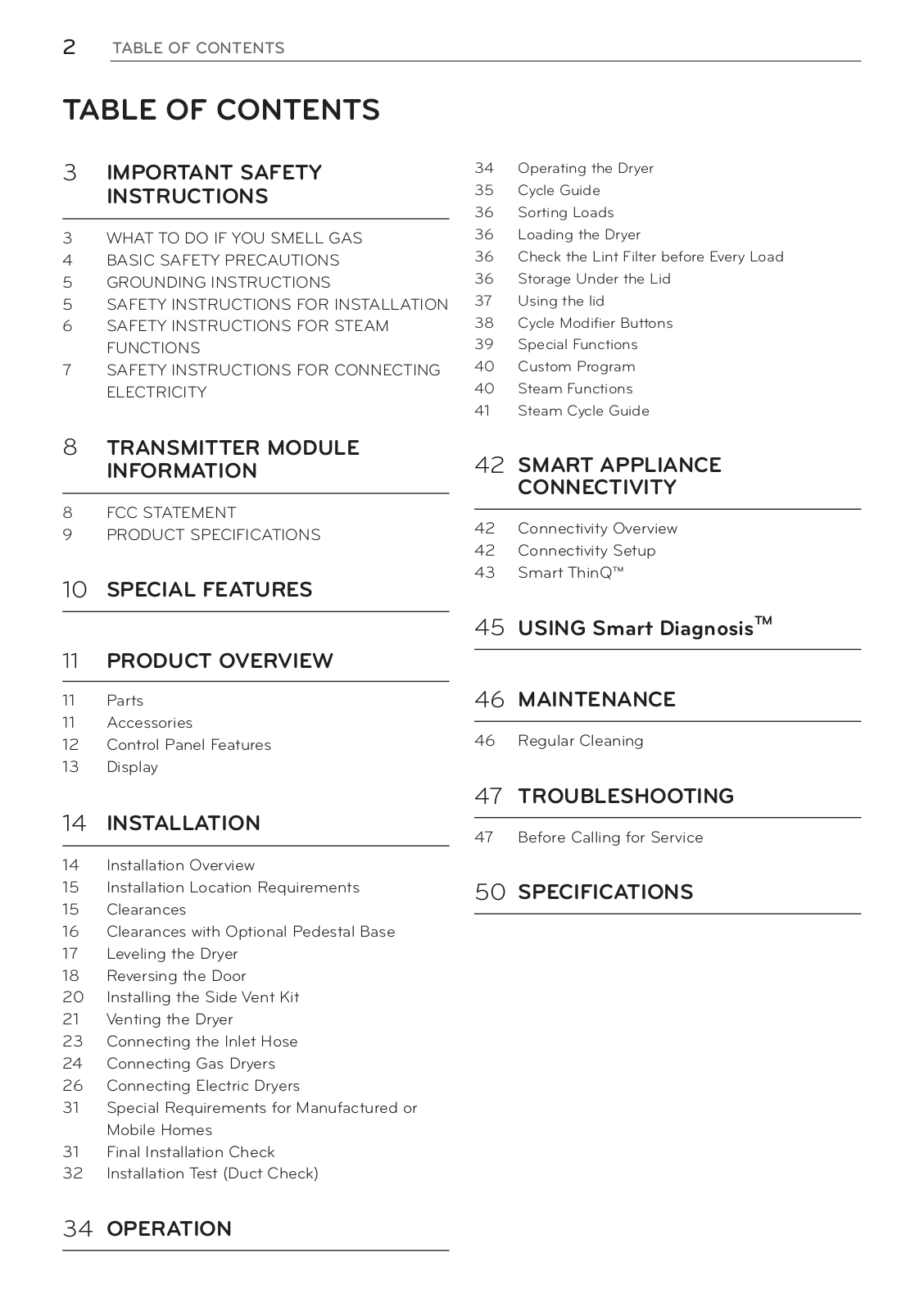
Table of contents
Loading...
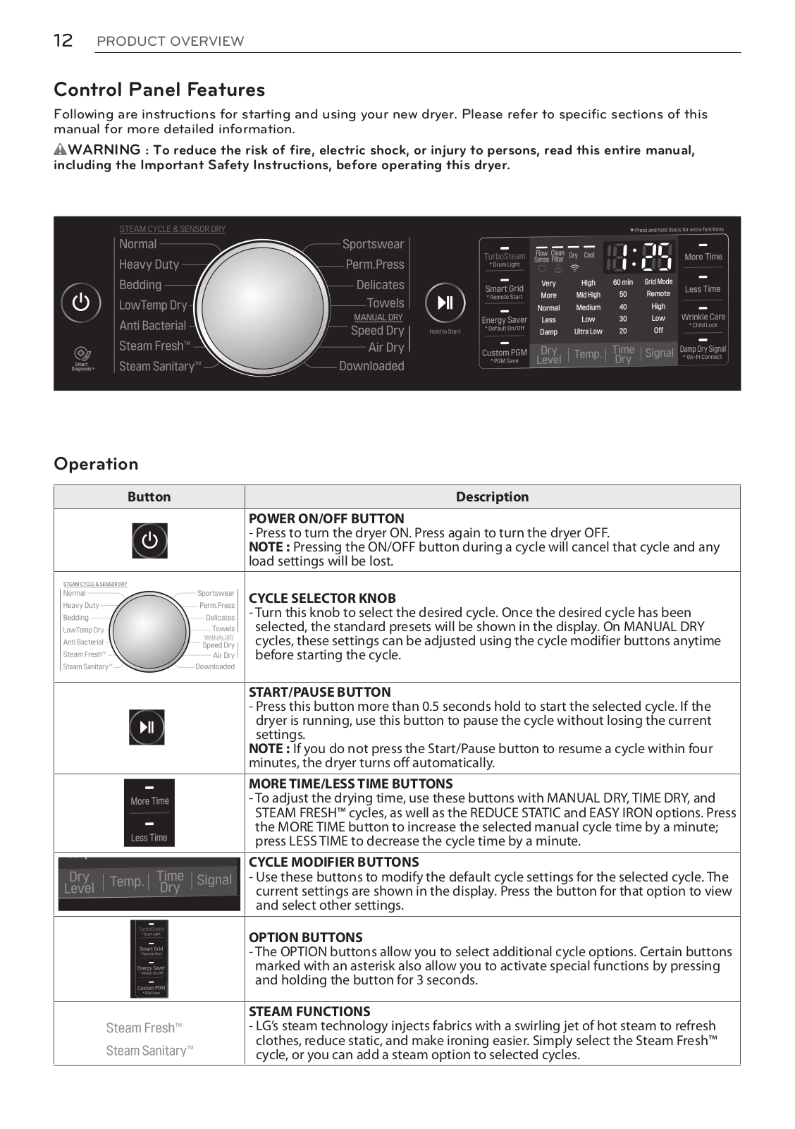
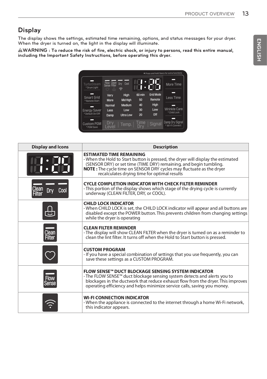
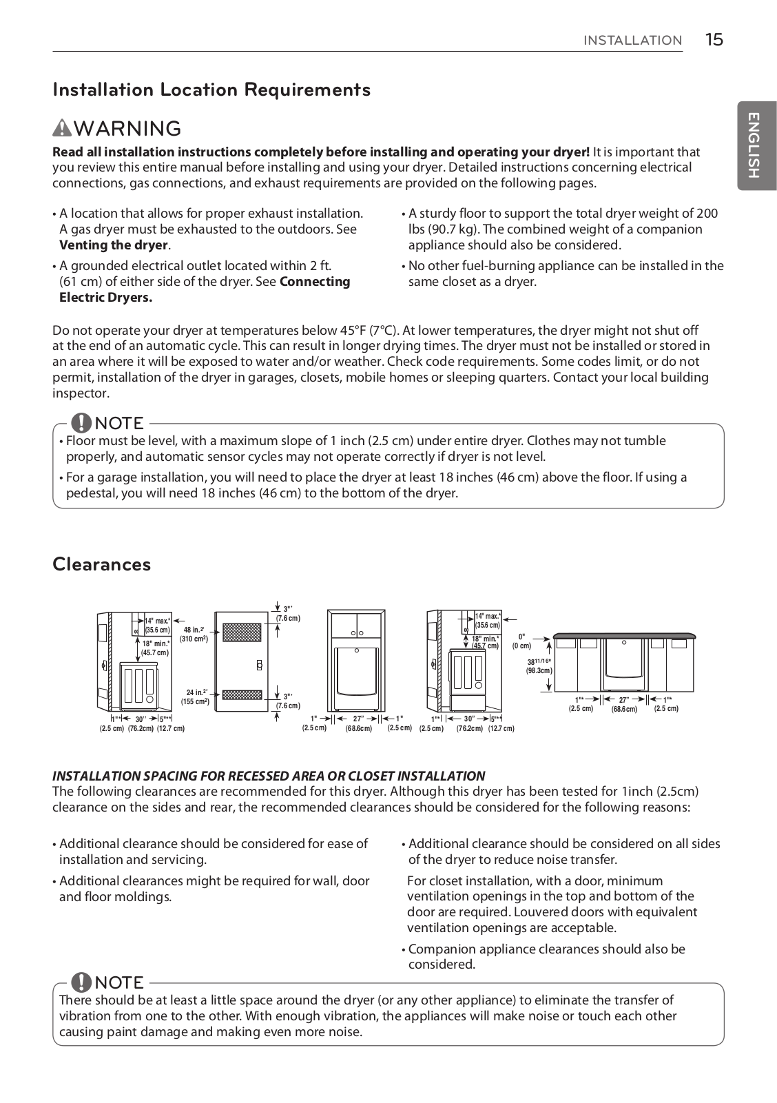
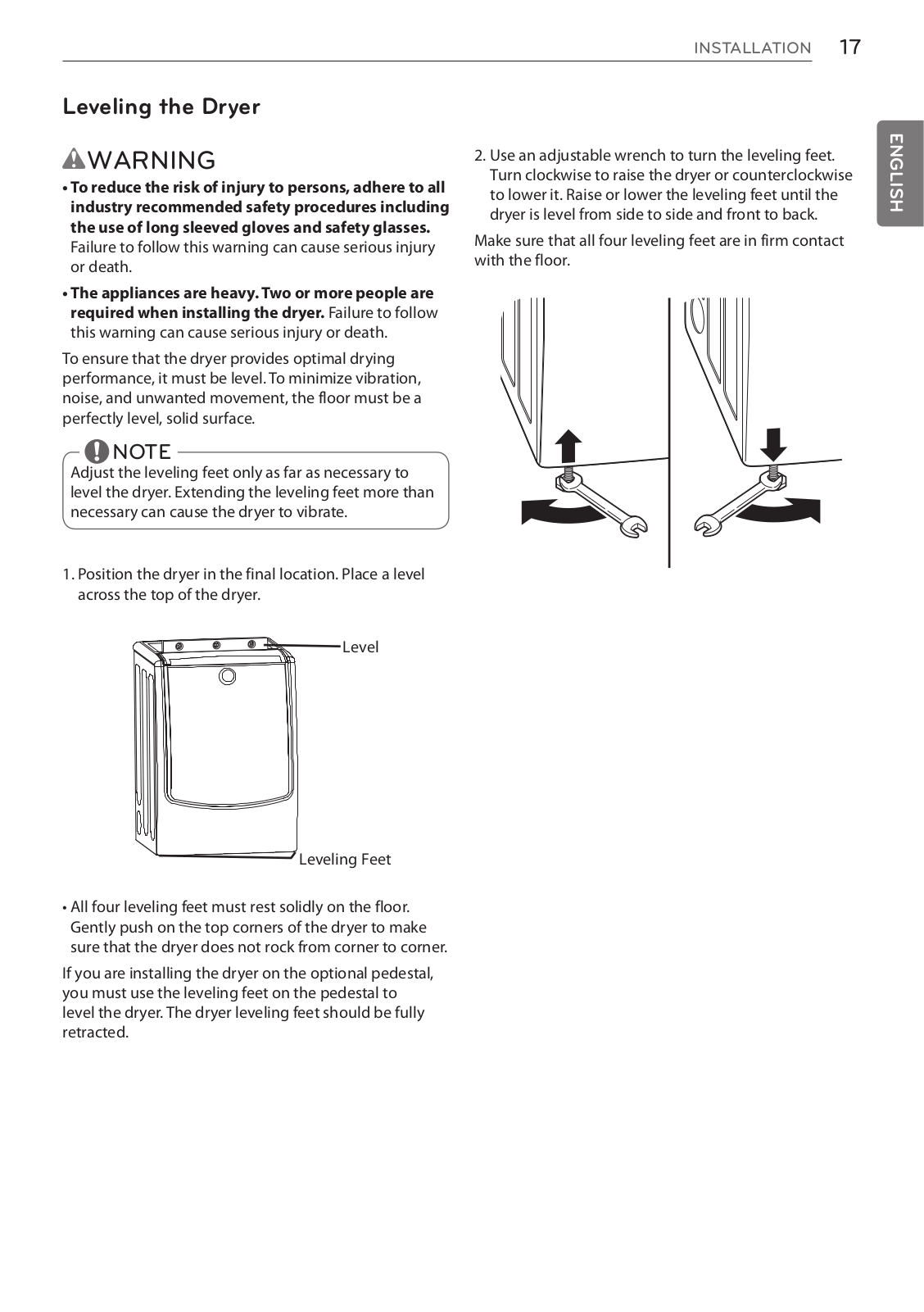
LG DLGX5001V Owner's manual
...
LG Owner's manual
Download
Specifications and Main Features
Frequently Asked Questions
User Manual
Download
Loading...
+
78
hidden pages
Unhide
You need points to download manuals.
1 point = 1 manual.
You can buy points or you can get point for every manual you upload.
Buy points
Upload your manuals
 Loading...