

Page 1

U.S.A. Website: http://us.lgservice.com
Canadian Website: http://lg.ca
ELECTRIC & GAS DRYER
SERVICE MANUAL
CAUTION
READ THIS MANUAL CAREFULLY IN ORDER TO
PROPERLY DIAGNOSE PROBLEMS AND TO SAFELY
PROVIDE QUALITY SERVICE ON THESE DRYERS.
MODEL : Electric Gas
DLEX3885* DLGX3886*
DLEX3875* DLGX3876*
Page 2

JAN. 2010 PRINTED IN KOREA
P/No.: MFL62119907
Page 3

2
To avoid personal injury, disconnect power before servicing this product. If electrical power is required
for diagnosis or test purposes, disconnect the power immediately after performing the necessary checks.
!
WARNING !
WHAT TO DO IF YOU SMELL GAS:
IMPORTANT SAFETY NOTICE
The information in this service guide is intended for use by individuals possessing skill and experience in
electrical, electronic, and mechanical appliance repair. Any attempt to repair a major appliance may result
in personal injury and property damage. The manufacturer or seller cannot be responsible for the
interpretation of this information, nor can it assume any liability in connection with its use.
RECONNECT ALL GROUNDING DEVICES
If grounding wires, screws, straps, clips, nuts, or washers used to complete a path to ground are
removed for service, they must be returned to their original position and properly fastened.
IMPORTANT
Electrostatic Discharge (ESD)
Sensitive Electronics
ESD problems are present everywhere. ESD may damage or weaken the electronic
control assembly. The new control assembly may appear to work well after repair is
finished, but failure may occur at a later date due to ESD stress.
■
Use an anti-static wrist strap. Connect wrist strap to green ground connection point or unpainted
metal in the appliance.
- OR -
Touch your finger repeatedly to a green ground connection point or unpainted metal
in the appliance.
■
Before removing the part from its package, touch the anti-static bag to a green ground connection
point or unpainted metal in the appliance.
■
Avoid touching electronic parts or terminal contacts; handle electronic control assembly by edges only.
■
When repackaging failed electronic control assembly in anti-static bag, observe above instructions.
■ Do not try to light a match, or cigarette, or turn on
any gas or electrical appliance.
■ Do not touch any electrical switches. Do not use
any phone in your building.
■ Clear the room, building or area of all occupants.
■ Immediately call your gas supplier from a
neighbor’s phone. Follow the gas supplier’s
instructions carefully.
■ If you cannot reach your gas supplier, call the fire
department.
Page 4

CONTENTS
1. SPECIFICATIONS ............................................................................................................... 4
2. FEATURES AND BENEFITS ............................................................................................... 6
3. INSTALLATION INSTRUCTIONS ........................................................................................ 6
4. DRYER CYCLE PROCESS ................................................................................................ 13
5. COMPONENT TESTING INFORMATION ......................................................................... 14
6. MOTOR DIAGRAM AND SCHEMATIC ............................................................................. 17
7. WIRING DIAGRAM ............................................................................................................ 18
8. STEAM FUNCTION ............................................................................................................ 19
8-1. STEAM CYCLE GUIDE ............................................................................................ 19
8-2. TROUBLESHOOTING FOR STEAM DRYER .......................................................... 20
8-3. DISPLAY FAULT/ERROR CODES FOR STEAM DRYER ........................................ 21
9. FLOW SENSOR FUNCTION ............................................................................................. 22
9-1. FLOW SENSOR ....................................................................................................... 22
9-2. INSTALLATION CHECK .......................................................................................... 23
9-3. TROUBLESHOOTING FOR FLOW SENSOR DRYER ............................................ 24
10. DIAGNOSTIC TEST ........................................................................................................ 25
10-1. TEST 1 120V AC ELECTRICAL SUPPLY ............................................................ 26
10-2. TEST 2 THERMISTOR TEST - MEZSURE WITH POWER OFF ......................... 29
10-3. TEST 3 MOTOR TEST ......................................................................................... 30
10-4. TEST 4 MOISTURE SENSOR .............................................................................. 31
10-5. TEST 5 DOOR SWITCH TEST ............................................................................. 32
10-6. TEST 6 HEATER SWITCH TEST - ELECTRIC TYPE .......................................... 33
10-7. TEST 7 GAS VALVE TEST - GAS TYPE .............................................................. 34
10-8. TEST 8 SEMI-CONDUCTOR ............................................................................... 35
10-9. TEST 9 MOTOR ASSEMBLY, DC, PUMP ............................................................ 35
10-10. TEST 10 GENERATOR ASSEMBLY .................................................................. 36
11. CHANGE GAS SETTING (NATURAL GAS, PROPANE GAS) ....................................... 37
12. DISASSEMBLY INSTRUCTIONS .................................................................................... 39
13. EXPLODED VIEW ............................................................................................................ 49
13-1-1. Control Panel and Plate Assembly (Touch LCD type) ......................................... 49
13-1-2. Control Panel and Plate Assembly 50
13-2. PANEL DRAWER ASSEMBLY and GUIDE ASSEMBLY ......................................... 51
13-3-1. CABINET and DOOR ASSEMBLY: ELECTRIC TYPE ........................................ 52
13-3-2. CABINET and DOOR ASSEMBLY: GAS TYPE .................................................. 53
13-4-1. DRUM and MOTOR ASSEMBLY: ELECTRIC TYPE ........................................... 54
13-4-2. DRUM and MOTOR ASSEMBLY: GAS TYPE ..................................................... 55
3
Page 5

1
SPECIFICATIONS
Name: Electric and Gas Dryer
Power supply: Please refer to the rating label regarding detailed
Size : 27 X 30 X 38.7 (inch)
Dryer capacity: IEC 7.4 cu.ft.
Weight: 136(lbs)
Specifications are subject to change by manufacturer.
ACCESSORIES
Dryer rack (1 each)
information.
Stacking kit (1 each)
Purchased Separately
Pedestal (1 each)
Purchased Separately
See page 6
See page 7 See page 8
4
Page 6
ITEM
DLEX3885* DLGX3886*
DLEX3875* DLGX3876*
REMARK
Color
Material &
Finish
Top Plate
Door Trim
POWER SUPPLY
MOTOR
ELECTRICITY
HEATER
CONSUMPTION
GAS VALVE
AG HEATER
DC, PUMP
CONTROL TYPE
DRUM CAPACITY
Weight (lbs) - Net/Gross
No. of Programs
LAMP
Blue White / Stainless Silver / Vintage Gold
Porcelain
Chromate
120V/240V 60Hz (26A)
250W (4.5A)
5400W (22.5A)
15 W (0.2A)
13 W (0.11A) x 2
1100W (9.2A)
2.4W (0.15A)
Electronic
7.4 cu.ft.
136 / 155.7
9
AC 120V
AC 240V (ELECTRIC MODEL)
AC 120V
AC 120V (GAS MODEL)
AC 120V (STEAM MODEL)
DC 9V (STEAM MODEL)
AC 240V (ELECTRIC MODEL)
No. of Dry Options
No. of Temperature Controls
No. of Dry Levels
Sound levels
Moisture
Sensor
Temperature
Reversible Door
Drum
Dryer Rack
Child Lock
Interior Light
Product (WxHxD)
Packing (WxHxD)
5
5
5
5
Available
Available
Available
Stainless Steel
Available
Available
Available
27" x 42 3/4" x 28 1/3"
29 1/2" x 44 3/4" x 30 3/4"
5
Electrode sensor, Dual Sensor
Thermistor, Dual Sensor
Page 7

2
FEATURES AND BENEFITS
3
Dryer Rack Installation Instructions
INSTALLATION INSTRUCTIONS
Open the door.
Hold the dryer rack
with both hands.
Put the dryer rack into
the drum
Check and be sure that the
front of the rack is properly
seated behind the lint filter.
6
Page 8
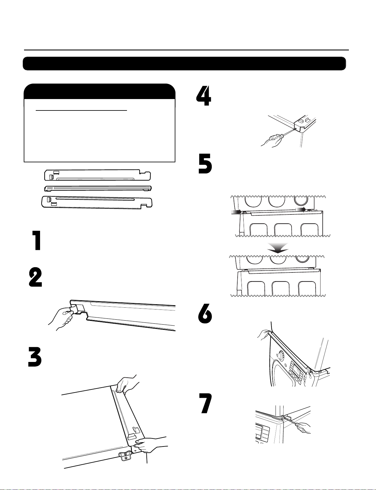
Stacking Kit Installation Instructions
To ensure safe and secure installation, please observe the instructions below.
WWAARRNNIINN GG
Do not attempt this alone!
At least two people are required to lift and
position the dryer on top of a washing
machine!
Failure to heed this warning can result in
serious physical injury and damage to the
appliance.
Stacking kit
Place the washer firmly on a stable, even
and solid floor as product installation
instructions describe in the owner’s
manual.
Secure the side bracket to the washer with
a screw on the back of the bracket. Repeat
Steps 2, 3, and 4 for the other side.
Place the dryer on top of the washer by
placing the legs as shown. Be careful not to
pinch fingers between the washer and dryer.
Slide the dryer back against the stop on the
side rail.
Peel the protective paper from the tape on
the side bracket.
Fit the side bracket firmly to the side of the
top plate by attaching the double-faced tape
to the top plate as picture shown.
Insert the front rail of the stacking kit. Push
the front rail back against the stops on the
side brackets.
Attach the front bracket to the side rails with
a screw on each side.
• Do not use a stacking kit with a gas dryer in
7
potentially unstable conditions like a mobile
home.
Page 9

Pedestal Installation Instructions
The pedestal accessory includes:
Drawer divider (1)
•
Screws (18) †
•
† Dryer installation only uses 8 screws
†† For dryer only
Wrench (1)
•
T-clips (4) ††
•
Tools Needed for Installation:
Phillips-head screwdriver
•
Wrench (supplied)
•
To ensure safe and secure installation, please
thoroughly follow the instructions below.
WARNING
• Incorrect installation can cause serious accidents.
• The appliances are heavy. Two or more people are
required when installing the pedestal. There is a
risk of serious back injury or other injuries.
• Do not allow children to play in or on the drawer.
There is a risk of suffocation or injury.
• Do not step on the handle. There is a risk of serious injury.
• If appliances are already installed, disconnect them
from all power, water, or gas lines and from draining or
venting connections. Failure to do so can result in
electrical shock, fire, explosion, or death.
• When installing, gloves must be put on.
Place the dryer on the
pedestal. Make sure
the front and back feet
are in the correct
positions. The dryer
feet will fit into the
innermost positions as
shown.
Make sure the screws on the pedestal align with the
holes in the retainers, then install 4 screws on each
side to securely attach the appliance to the pedestal.
NOTE: If the screws are not installed properly, noise
and vibration may result.
Move the appliance to the desired location.
Loosen the locknuts on all 4 leveling feet of the
pedestal until you can turn them with the wrench.
Turn clockwise to raise or counterclockwise to lower
until the pedestal is level and all 4 feet are solidly
against the floor.
For dryer
For washer/combo
Make sure the leveling feet of the dryer are
fully retracted.
NOTE: The appliance and pedestal assembly
must be placed on a solid, sturdy, level floor
for proper operation.
Retract fully
Insert the T-clip of the 4 retainers into the dryer
base as shown. Press up on the back of the
clip and pull outward to lock into place.
T-clip
Retainer
Raise
Securely tighten all locknuts by hand.
NOTE: Noise and vibration may result if locknuts are not
tightened.
Be sure to connect the appliances to all water, power,
or gas lines and draining or venting connections before
operation.
If there is excessive vibration during the first operation
after installation, slightly adjust the leveling feet.
8
Locknut
Lower
Page 10
9
Use the instructions under option 2 or 3 if your
home has a 3-wire receptacle (NEMA type 10-30R).
Use option 2 if local codes and ordinances permit
the connection of a chassis ground to the neutral
connector. If this is not permitted, use option 3.
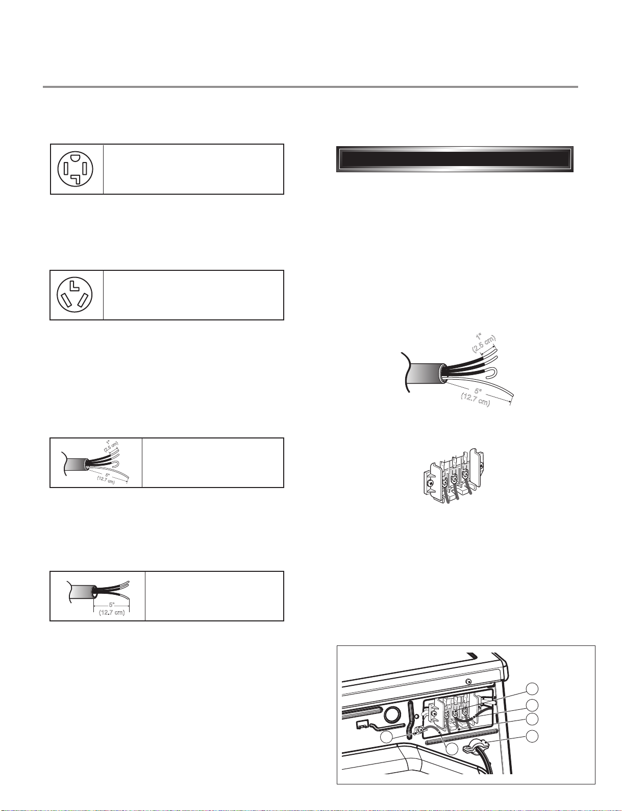
Review the following options to determine the appropriate electrical connection for your home:
Electric Dryer Only
If this type is available at your home. you will be
connecting to a fused disconnect or circuit breaker
box
Important :Grounding through the neutral conductor
is prohibited for (1) new branch-circuit installations,
(2) mobile homes, and (3) recreational vehicles, and
(4) areas where local codes prohibit grounding through
the neutral conductor.
Prepare minimum 5ft(1.52m) of length in order for
dryer to be replaced.
First, peel 5 inch (12.7cm) of covering material from
end. Make a 5 inch of ground wire bared. After cutting
1
1
/2 inch (3.8cm) from 3 other wires. peel insulation
back 1inch (2.5cm). Make ends of 3 wires a hook
shape.
Then, put the hooked shape end of the wire under the
screw of the terminal block(hooked end facing rightward)
and pinch the hook together and screw tightly.
Use the instructions under option 1 if your home
homehas a 4-wire receptacle (NEMA type 14-30R).
If this type is available at your home. you will be
connecting to a fused disconnect or circuit breaker
box
1. Connect neutral wire(white) of power cord to center
terminal block screw.
2. Connect red and black wire to the left and right
terminal block screws.
3. Connect ground wire(green) of power cord to external
ground screw and move neutral ground wire of
appliance and connect it to center screw.
4. Make sure that the strain relief screw is tightened.
and be sure that all terminal block nuts are on tight and
power cord is in right position.
1"
(2.5 cm)
5
"
(12.7 cm)
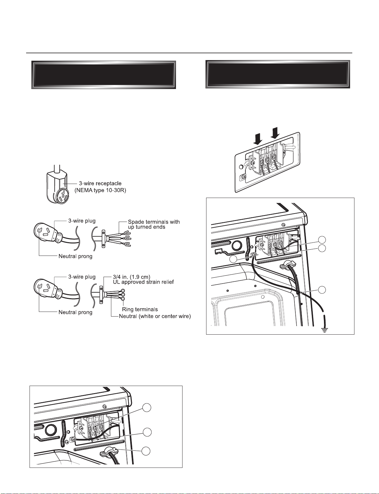
3-wire direct
4-wire receptacle
(NEMA type14-30R)
3-wire receptacle
(NEMA type10-30R)
4-wire direct
5"
(12.7 cm)
4-wire connection : Direct wire
1"
(2.5 cm)
5
"
(12.7 cm)
D
E
F
a
C
b
Page 11

10
Important : Grounding through the neutral conductor
is prohibited for (1) new branch-circuit installations,
(2) mobile homes, and (3) recreational vehicles, and
(4) areas where local codes prohibit grounding through
the neutral conductor.
Prepare minimum 5ft(1.52m) of length in order for
dryer to be replaced.
First, peel 3
1
/2 inch (8.9cm) of covering material
from end and bare 1 inch from the ends.
1. Connect neutral wire(white) of power cord to
center terminal block screw.
2. Connect red and black wire to the left and right
terminal block screws.
3. Make sure that the strain relief screw is tightened
and be sure that all terminal block nuts are on
tight and power cord is in right position.
Then, put the hooked shape end of the wire under
the screw of the terminal block(hooked end facing
rightward) and pinch the hook together and screw
tightly.
1
"
(
2
.
5
c
m
)
3V
2
"
(8.9 cm)
3-wire connection : Direct wire
1. Connect the neutral wire (white) of the power
cord to the center terminal block screw.
2. Connect the red and black wires to the left and
right terminal block screws.
3. Connect the ground wire (green) of the power
cord to the external ground screw. Remove the
neutral ground wire of appliance and connect it to
center screw.
4. Make sure that the strain relief screw is tightened
and that all terminal block nuts are tight and the
power cord is in the right position.
F
a
b
E
D
C
• lf your local codes or ordinances do not allow the
use of a 3 wire connection, or you are installing
your dryer in a mobile home, you must use a
4-wire connection.
Option 1: 4-wire connection with
a Power supply cord.
C
B
D
a
E
Page 12
11
1. Remove the appliance ground wire (D) (green)
fromthe external ground connector screw and
reconnect it, together with the center, white,
neutral wire (E) to the center, silver colored,
terminal block screw.
2. Connect the other two power cord wires (red and
black) to the left and right terminal block screws
and tighten securely.
3. Tighten the strain relief screws securely.
4. Connect an independent ground wire (F) from the
external ground connector screw to a proper
ground. (The ground wire must be long enough to
allow the appliance to be moved, if necessary, for
service or cleaning.)
C
B
A
lf your local codes or ordinances permit the
connection of a frame-grounding conductor to the
neutral wire, use these instructions. If your local
codes or ordinances do not allow the connection of
a frame-grounding conductor to the neutral wire,
use the instructions under Option 3: Optional
3-wire connection.
1. Connect the neutral (white or center) wire (B) to
the center, silver colored, screw (A) and tighten
securely.
2. Connect the other two power cord wires (red and
black) to the left and right terminal block screws
and tighten securely.
3. Tighten the strain relief screws (C) securely.
Option 2: 3-Wire Connection with
a Power Supply Cord
• If your local codes or ordinances do not allow the
connection of a frame-grounding conductor to the
neutral wire, use the instructions under this
section.
E
A
D
F
Option 3: Optional 3-wire
connection.
Page 13

12
3-2. Connect Gas Supply Pipe (Gas Dryer ONLY)
2
3
5
1
4
1. Make certain your dryer is equipped for use with the
type of gas in your laundry room. Dryer is equipped
at the factory for Natural Gas with a
3
/8” NP T gas
connection.
2. Remove the shipping cap from the gas connection
at the rear of the dryer. Make sure you do not
damage the pipe thread when removing the cap.
3. Connect to gas supply pipe using a new flexible
stainless steel connector.
4. Tighten all connections securely. Turn on gas and
check all pipe connections (internal and external) for
gas leaks with a non-corrosive leak detection fluid.
5. For LP (Liquefied Petroleum) gas connection, refer
to section on Gas Requirements.
For further assistance, refer to section on Gas Requirements.
1 New Stainless Steel Flexible Connector - Use
only if allowed by local codes (Use Design
A.G.A. Certified Connector)
2
1
/8” NPT Pipe Plug
(for checking inlet gas pressure)
3 Equipment Shut-Off Valve-Installed within 6’
(1.8 m) of dryer
4 Black Iron Pipe
Shorter than 20’ (6.1 m) - Use
3
/8” pipe
Longer than 20’ (6.1 m) - Use
1
/2” pipe
5
3
/8” NPT Gas Connection
Page 14

4
Cycle
Default
Conditions of operation and termination
Tem p-
erature
Dry
Level
Display
time
Sensor
Dry *
Manual
Dry **
STEAM FRESH
TM
ANTIBACTERIAL
BULKY /
LARGE
HEAVY DUTY
PERM PRESS
CASUAL
COTTON /
NORMAL
DELICATES
TOWELS
SMALL LOAD
SPORTS
WEAR
STEAM
SAINTARY
TM
SPEED DRY
AIR DRY
FRESHEN UP
HIGH
MEDIUM
MEDIUM
Off
Off
Off
Off
Off
Ver y
Dry
HIGH
HIGH
HIGH
LOW
HIGH
NO
HEAT
20min
Saturation
Saturation
Saturation
Saturation
Saturation
Saturation
Saturation
Saturation
Saturation
Saturation
Saturation
Saturation
66±4˚C 45 ±5˚C
45 ±5˚C
45 ±5˚C
45 ±5˚C
45 ±5˚C
38 ±5˚C
(47 ±5˚C)
45 ±5˚C
45 ±5˚C
45 ±5˚C
68±4˚C
68±4˚C
68±4˚C
60±4˚C
52±3˚C
66±4˚C
68±4˚C
60±4˚C
(68±5˚C)
(66±5˚C)
5min
5min
5min
5min
5min
5min
5min
5min
5min
5min
5min
39min
70min
Normal
Adjustable
LOW
Saturation
45 ±5˚C
52±3˚C
5min
32min
54min
41min
28min
55min
30min
27min
15min
30min
25min
Drying Cooling
Wrinkle care
Time
Electro-
sensor
Te mp-
Control
Default
time
Temp-
Control**
3Hr
3Hr
Load
Motor
Heater
Temperature Control for each cycl e
Off Time: 6min
On Time: 10sec
*Sensor dry : Dry Level is set by users.
**Manual dry : Temperature control is set by users.
Default settings can be adjusted by users.
HIGH
HIGH
MEDIUM
Mid High
Normal
Adjustable
MEDIUM
Saturatio
n
45 ±5˚C
60±4˚C
5min
55min
Normal
Adjustable
Normal
Adjustable
Normal
Adjustable
Normal
Adjustable
Normal
Adjustable
(66±5˚C)
5min
(45 ± 5˚C)
DRYER CYCLE PROCESS
13
Page 15
14
When checking the component, be sure to turn the power off, and do voltage discharge sufficiently.
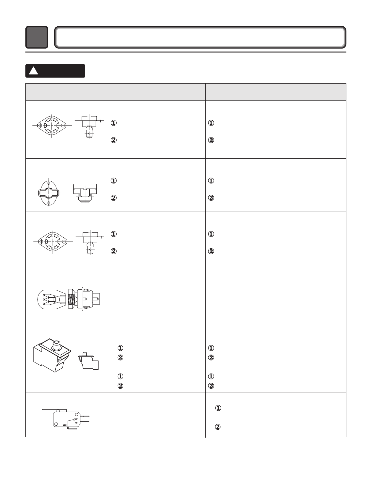
COMPONENT TESTING INFORMATION
5
!
CAUTION
Component Test Procedure Check result Remark
1. Thermal cut off
• Check Top Marking:
N130
Measure resistance of terminal
to terminal
Open at 266±12°F
(130±7°C)
Auto reset 31°F (35°C)
Same shape as Outlet Thermostat.
If thermal fuse is open must
be replaced
Resistance value ≒∞
Continuity (250°F ↓) < 1Ω
• Heater caseSafety
• Electric type
2. Hi limit Thermostat
(Auto reset)
Measure resistance of terminal
to terminal
Open at 257±9°F
(125±5°C)
Close at 221±9°F
(105±5°C)
Resistance value ≒∞
Resistance value < 5Ω
• Heater case Hi limit
• Electric type
3. Outlet Thermostat
( Auto reset)
• Check Top Marking:
N85
Measure resistance of terminal
to terminal
Open at 185±9°F
(85±5°C)
Close at 149±9°F
(65±5°C)
Same shape as Thermal cut off.
Resistance value ≒∞
Resistance value < 5Ω
• Blow housing Safety
• Electric type
4. Lamp holder Measure resistance of terminal
to terminal
Resistance value:
80Ω ~ 100Ω
6. Idler switch Measure resistance of the
following terminal:
COM - NC
1. lever open
Resistance value < 1Ω
2. Lever push (close)
Resistance value ≒∞
5. Door switch Measure resistance of the
following terminal
1) Door switch knob: open
Terminal: COM - NC (1-3)
Terminal: COM - NO (1-2)
2) Door switch push: push
Terminal: COM - NC (1-3)
Terminal: COM - NO (1-2)
Resistance value < 1Ω
Resistance value ≒∞
Resistance value ≒∞
Resistance value < 1Ω
The state that
Knob is
pressed is
opposite to
Open
condition.
Page 16
15
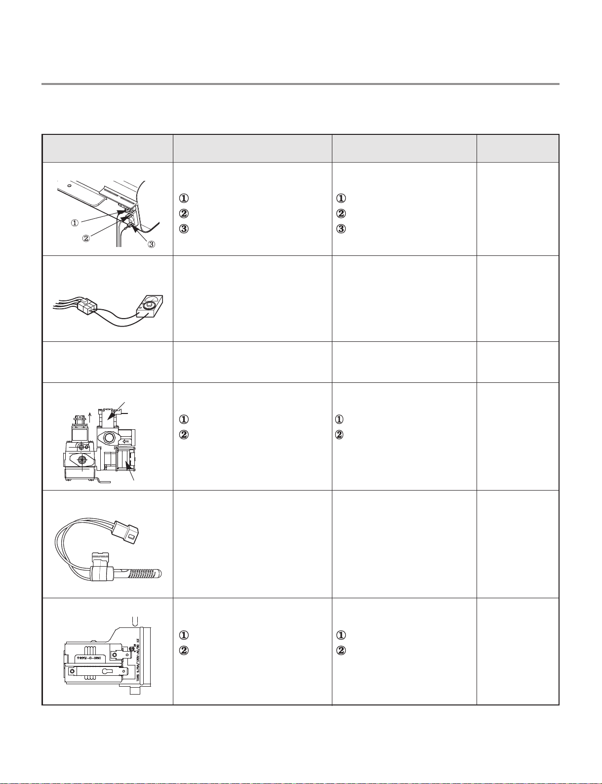
Component Test Procedure Check result Remark
7. Heater Measure resistance of the
following terminal
Terminal: 1 (COM) - 2
Terminal: 1 (COM) - 3
Terminal: 2 - 3
Resistance value: 10Ω
Resistance value: 10Ω
Resistance value: 20Ω
• Electric type
8. Thermistor Measure resistance of terminal
to terminal
Temperature condition:
58°F ~ (10~40°C)
58°F ~ 104F (10~40°C)
Resistance value: 10Ω • Heater case -
Hi limit
• Electric type
9. Motor • See Page 13
10. Gas valve
valve 1
valve 2
Measure resistance of the
following terminal
Valve 1 terminal
Valve 2 terminal
Resistance value: > 1.5 kΩ
Resistance value: >
1.5~2.5 kΩ
• Gas type
11. Igniter Measure resistance of terminal
to terminal
Resistance value: 100~800Ω • Gas type
12. Flame Detect Measure resistance of terminal
to terminal
Open at 370°F ((Maximum)
Close at 320°F
Resistance value ≒∞
Resistance value < 1Ω
• Gas type
Page 17

16
Component Test Procedure Check result Remark
13. Outlet Thermostat
(Auto reset)
• Check Top Marking:
N95
Measure resistance of terminal
to terminal
Open at 203±7°F (95±5°C)
Close at 158±9°F (70±5°C)
Resistance value ≒∞
Continuity < 1Ω
• Gas type
• Gas funnel
14. Outlet Thermostat
(Manual reset)
• Check Top Marking:
N110
Measure resistance of terminal
to terminal
Open at 212±12°F
(110±7°C)
Manual reset
If thermal fuse is open must
be replaced
Resistance value ≒∞
Continuity < 1Ω
• Gas type
• Gas funnel
Page 18

17
MOTOR DIAGRAM AND SCHEMATIC
6
Contact On / Off by Centrifugal Switch
STOP MODE
(When Motor does not operate)
RUN MODE
(Motor operates)
When checking component, be sure to turn power off, then do voltage discharge sufficiently.
NOTE
Centrifugal switch
Centrifugal switch
(Pull Drive forward)
Page 19

18
WIRING DIAGRAM
7
ELECTRIC DRYER WIRING DIAGRAM
GAS DRYER WIRING DIAGRAM
Page 20

8
STEAM FUNCTION
8-1.
STEAM
SANITARY
STEAM
FRESH
STEAM
OPTION
Steam Cycle Guide
STEAM
TM
REDUCE
TM
STATIC
REDUCE
STATIC
+
+
EASY
IRON
+
+
EASY
IRON
DEFAULT TIME
STEAM SANITARY
(39 minutes)
STEAM FRESH
(20 minutes)
STEAM FRESH
(10 minutes)
STEAM FRESH
(12 minutes)
HEAVY DUTY
COTTON/TOWELS
NORMAL
PERM.PRESS
DELICATES
TM
TM
TM
TM
TEMP.
CONTROL
O
DRY
LEVEL
O
O
FABRIC
STATE
Dry
Dry
Dry
Dry
Wet
Wet
FABRIC TYPE
Comforter
Bedding
Children’s clothing
Comforter
Shirts*
Shirts*
Follow selected
cycle
Follow selected
cycle
MAXIMUM
AMOUNT
Single (1 each)
3 lbs.
Single (1 each)
5 each
8 lbs.
(18 Items.)
Shirts* (5 each)
8 lbs.
(18 Items.)
Shirts* (5 each)
TIME
DRY
+
REDUCE
STATIC
+
EASY
IRON
TIME DRY
(45 minutes)
TIME DRY
(47 minutes)
O
O
Wet
Wet
Follow selected
temp
Follow selected
temp
8 lbs.
(18 Items.)
Shirts* (5 each)
*Shirt: 70% cotton/30% poly blend. Except especially delicate fabrics.
• When the lint filter or exhaust duct is clogged, steam options will not give proper results.
• For best results, load articles of similar size and fabric type. Do not overload.
IMPORTANT NOTES ABOUT STEAM CYCLES:
•
The steam feeder must be filled with water up to the MAX line. Otherwise, an error message
will be displayed.
• If the lint filter or exhaust duct is clogged, the steam options will not give proper results.
• For best results, load articles of similar size and fabric type.
Do not overload.
• Water only - Do not add any additives or other materials as these will damage your dryer.
• Before moving the dryer, make sure the steam feeder is empty.
• Best results are obtained with cotton/poly blend fabrics.
19
Page 21

8-2. Troubleshooting for Steam Dryer
PROBLEM
The display shows: • Water supply error.
Water drips from
nozzle when Steam
Cycle starts.
Steam doesn’t
generate but no error
code is shown.
Garments still
wrinkled after
STEAM FRESH™.
POSSIBLE CAUSES
• This is normal. • This is steam condensation. The dripping water
• Water level error. • Unplug dryer and call for service.
• Too many or to different
types of garments in
dryer.
SOLUTIONS
• Check steam feeder drawer:
(1) Make sure steam feeder is filled with water to
MAX line.
(2) Make sure steam feeder is seated properly
and drawer is fully cloased.
(3) Turn the dryer off then restart the steam cycle.
• Do not use distilled water; the water level sensor in
steam generator will not work.
• Pump not working. Unplug dryer and call for service.
will stop after a short time.
• Small loads of 1 to 5 items work best.
• Load fewer garments. Load similar-type garments.
There are no creases
left on garment after
STEAM FRESH™.
Garments have
static after REDUCE
STATIC.
Garments are too
damp or too dry after
REDUCE STATIC.
Garments are not
uniformly damp after
EASY IRON.
Water drips from door
during Steam Cycle.
Steam is not visible
during Steam Cycle.
Drum does not turn
during Steam Cycle.
• The function of this cycle
is to remove wrinkles
from fabric.
• This is normal. • Depends on individual moisture level in skin.
• Correct drying options
not selected.
• This is normal. • Depends on the amount or type of garments.
• This is normal. • This is steam condensation on door surface.
• This is normal. • Steam vapor is difficult to see when the door is
• This is normal. • The drum is turned off so that the steam vapor
• Use an iron to make creases.
• Select load weight manually before starting
REDUCE STATIC option.
closed.
remains in the drum.
20
Page 22

PROBLEM
POSSIBLE CAUSES
SOLUTIONS
Cannot see steam
vapor at the
beginning of cycle.
The display shows
BULKY LOAD.
Odors remain in
clothing after
STEAM FRESH™.
• This is normal. • Steam is released at different stages of the cycle
for each option.
• MORE TIME button
pressed.
• STEAM FRESH™ did
not remove odor
completely.
• Pressing the MORE TIME button several times will
set the cycle for a large load such as a comforter.
• Fabrics containing strong odors should be washed in
a normal cycle.
8-3. Display Fault/Error Codes for Steam Dryer
The error codes below will be displayed when attempting to start a drying cycle or after
activating the Diagnostic Test mode.
DISPLAY
tE1
CHECKING PART CAUSE
Thermistor of blower
housing
Outlet thermistor open or shorted.
• tE1 error is displayed in the
drying cycle or test mode.
• Replace the steam generator.
REMARK
tE2
tE4
E5
Add water
Thermistor of blower
housing
Thermistor of steam
generator
Water supply pump
Steam generator
Outlet thermistor open or shorted.
Steam generator thermistor open
or shorted.
When the pump valve is less than
10 in the test mode
Sensors do not detect that steam
generator is full within 60 seconds.
21
• tE2 error is displayed in the
drying cycle or test mode.
• Replace the steam generator.
• tE4 error is only displayed in the
test mode.
• Replace the steam generator.
• tE5 error is only displayed in the
test mode.
• Check the connection between
harness wire and connector.
• Replace the water supply pump.
• If water in the steam feeder is
not enough this error may be
displayed. Fill the feeder and
restart the cycle.
Page 23

9
FLOW SENSOR FUNCTION
9-1 Flow sensor
This FlowSense
Clogged duct vents or hoses decrease efficiency in drying cloths. Clogged vents can also cause fire.
This function alerts you to the need of cleaning the duct.
When the alarm about Duct clogging is on display of the panel, your duct vents should be cleaned by
yourself or serviceman.
TM
function detects the clogging or blocking of ducts.
Flow Sensor Function
How does the Flow sense function display the clogging of duct ?
TM
The FlowSense
inside a box. The display has only three possible
displays as only three possible displays as shown
here (Also see the figure shown below):
1
No bars displayed.
display consists of four bars
4 Bars 2 Bars NO Bars
CLOGGED
Check and
Clean Duct.
NORMAL
Duct OK. The
Dryer can work.
2
2 bars displayed.
3
4 bars displayed.
22
Page 24

9-2 Installation check
This feature allows you to quickly verify that the exhaust system is adequate for the normal function of the
dryer. The check takes only two minutes. The results of the check are displayed in the FlowSense
display window as shown below
(Fig. 1). The dryer must be at room temperature for this test to be reliable. To perform this test, start the
machine in standby mode (power off). Press and hold both the DAMP DRY BEEP and the TEMP CONTROL
buttons together while turning on the dryer with the POWER button i.e. Press together the three buttons
DAMP DRY BEEP + TEMP CONTROL + POWER. The dryer will start and run for 2 minutes while it checks
temperatures. At the end of this short cycle, it will display the results as follows.
Fig.1
TM
PRESS TOGETHER
After Installation Check,
If duct shows….
(Three buttons)
If NO Bars are shown in the
display, ductwork is free from
any blocking or restrictions.
OR
If 4 Bars are shown in the display,
ductwork is blocked and need to
be cleaned immediately.
23
Page 25

9-3 Troubleshooting for flow sensor dryer
1. Flow sensor bars light up
Is lint filter full?
Is duct clogged?
Yes
No
Yes
Clean lint filter before every load
Check & clean duct.
2. Flow sensor bars light up and does not disappear.
1. Flow sensor lights up 2 bars even when vents have been clean and even when the vents are off.
This is Normal. After flow sensor recheck full next cycle, flow sensor is reset.
(Flow sensor bars will disappear after dryer has operated two cycle)
2. Is flow sensor display changed from 4 bars to 2 bar after cleaning the duct.
Ductwork is slightly too long or has too many elbows.
Dryer can be used in this condition.
Bars are displayed and do NOT disappear
*Control Panel
Make sure that the ductwork is not
crushed or restricted.
or
Avoid long runs of ducts or runs
with multiple elbows or bends.
Check for blockages and lint build up.
24
Page 26

10
1.This TEST should be used for Factory test /Service test. Do not use this DIAGNOSTIC TEST other than specified.
2.Activating the Heater manually with the Door open may trip the Thermostat attached to the Heater, therefore do not
activate it manually. (Do not press the door switch to operate the heater while the door is open )
DIAGNOSTIC TEST
ACTIVATING THE DIAGNOSTIC TEST MODE
1. UNIT must be in standby (unit plugged in, display off)
2. Press POWER while pressing MORE TIME and LESS TIME simultaneously.
3. Press START/PAUSE button to advance through diagnostics.
Pressing the
START/PAUSE
CHECKING
ACTION
Electric control
None
Temperature sensor
Once Motor+Controller
ELECTRIC TYPE
Twice
Motor+Heater1(2700W)
GAS TYPE
Motor
ELECTRIC TYPE
Motor+Heater1+Heater2
3 times
(5400W)
GAS TYPE
Motor+Gasvalve
Motor+Pump+
4 times
Heater2(runs for 1sec)
(Heater1 off)
5 times
6 times
Motor, Pump, Heater2 off
Loads, Controller off
DISPLAY CHECKPOINT
LQC TEST MODE
VERSION
ELECTRODE : XXX
TEMPERATURE1 : XXX
SG TEMP. : XXX
&
SG Short : XXX
TEMPERATURE2 : XXX
239 = High
Current Temp.
Current Temp.
Pump AD valve
GAS or ELECTRIC
SG PUMP : XXX
SG LONG : XXX
HUMIDITY : XXX
30 = Low
moisture
moisture
(5~70)
(5~70)
(11~255)
E5
OO
Standard
Thermistor opentE1
Thermistor shortedtE2
AG Thermistor open or shortedtE4
Motor runs
Displays Moisture Sensor Operation
If moisture sensor is contacted with
damp cloth. The display number is
below180innormalcondition
ELECTRIC TYPE Heater 1 is energized
- 2700 W
GAS TYPE is not opened
(Temperature in the drum is displayed in
degrees C.)
ELECTRIC TYPE: Heater 1 and heater 2 are
energized - 5400 W
GAS TYPE: Gas valve is energized (Temperature in
the drum is displayed in degrees C.)
DUAL SENSOR FAILURE CHECK :
Values of TEMPERATURE2 and HUMIDITY are
‘000’, the display shows SE ERROR.
Pump runs
Pump Error
Power off
To check pump operation:
When pressed 4 times in the test mode, If the AD value of the pump is higher than 10 on the display, the pump is normal.
If it is lower than 10, E5 error will be displayed.
25
Page 27

26
Test 1
120V AC Electrical supply
Caution
Trouble Symptom
Measurement Condition
When measuring power, be sure to wear insulated gloves to avoid an
electric shock.
No power was applied to Controller. (LED,LCD Display off)
With Dryer Power On; Connector linked to Controller.
Check the outlet, is the voltage
110V ~ 125V AC?
YES
NO
• Check the fuse
or circuit breaker.
Check if the voltage measured between
Connector BK2 or WH2-
(Black Wire)
Linked to the Controller and WH1(White Wire) Is 110~125V?
YES
NO
1 12
BK2 or WH2
WH1
BK WH
• Check if Power
Cord is properly
connected.
• Reconnect the
controller.
Replace controIler.
Check if the Controller wire is
disconnected.
Check if Terminal Block and Power Cord
are connected (Check Plug ).
- Does Power Cord N neutral line match
to center terminal N neutral line?
YES
NO
L (Black) L (Red)
N (White)
Page 28

Caution
Trouble Symptom
Measurement Condition
1
2
1
2
When measuring power, be sure to wear insulated gloves to avoid an electric shock.
Check the Tab Relays Connection properly.
With Dryer Power On; Connector linked to Controller.
1. Power Connection
< Table1 > : Connection of the tap relay with Heater (Electric)
Tab Relay 1
High
Mid High
Medium
Low
Extra Low
on
on
Tab Relay 2
on
off
Heater 1 Heater 2
on
on
on
off
Temperature Control below 68 4
Turn on Heater1 and Heater2.
Temperature Control below 52
Only Turn on Heater1.
< Table 2 > : Connection of the Tab Relay with Burner (Gas)
Tab Relay 1 Burner Remark
High
Mid High
Medium
Low
Extra Low
Tab Relay 1
O O
O O
Tab Relay 2
Temperature Control below 70
Turn on Burner
Temperature Control below 47 4
Turn on Burner
Trans
Remark
4
4
PCB ASSEMBLY LAYOUT
2. Status Mode Of The Connection
< Table1 > : Connection of tap relay with the tap relay of the PCB ASSEMBLY Electric
Connector Housing
Color
Black
White
Connection
Harness
Yellow wire
Black wire
Connector Housing Tap relay 1
Blue wire
Black wire
Connector Housing Tap relay 2
PCB
27
Remark
Check the Matching color Between
Harness wire and tap relay.
(Black Housing – Black tap relay)
Check the Matching color Between
Harness wire and tap relay.
(White Housing – White tap relay)
Page 29

28
3. Status Mode Of wrong Connection
1.Black and White Housing
2.Black Housing
3.White Housing
4.Black and White Housing
5.Black and White Housing
Off
Off
Normal
Heater2
Off
Off
Off
Normal
Heater1
Off
Power Off
Power Off
Power On
Power On
Power Off
Wire ①, ②CROSS
Wire ①, ②CROSS
Wire ①, ②CROSS
Housing CROSS
Housing and Wire ①,
②
CROSS
Items
Case
Heater1
Operation(black)
Heater2
operation(White)
PCB condition
of operation
ffOgnisuoH etihW dna kcalB.1
Off
Power Off
Wire ①, ②CROSS
Items
Case
Heater1
Operation (black)
Heater2
operation (White)
PCB condition
Of operation
CAUTION! Improper connection of the heater can damage the heater or the main board.
!
CAUTION
Connector Housing
Black
Check the Matching color Between
Harness wire and tap relay.
(Black Housing – Black tap relay)
Color
< Table 2 > : Connection of tap relay with PCB ASSEMBLY (Gas)
< Table1 > : incorrect Connection of the tap relay and connector housing (Electric)
< Table2 > : incorrect Connection of the tap relay and connector housing (Gas)
Harness
Remark
PCB
Tap relay 1
1
2
Blue Wire
Black Wire
Connector Housing
Page 30

29
Test 2
Thermistor Test --- Measure with Power Off
Caution
Trouble Symptom
Measurement Condition
Before measuring resistance, be sure to turn Power off, and do voltage discharge.
(When discharging, contact the metal plug of Power cord with the Ground.)
During Diagnostic Test, tE1 and tE2 Error occur.
During operation, Heater would not turn off or remains on.
Difference between actual and sensed temperature is significant.
After turning Power off, measure the resistance.
Short with metal to the 6 pin connector’s
Pin
(Blue Wire) and
Pin
(Orange Wire) to Controller.
NO
YES
• Check if Control
and the 6 pin
connector are
properly
connected.
• Replace
Controller.
Check Harness-linking connector.
Take the 6 pin Connector
from the Controller.
Table 1. Resistance for Thermistor Temperature.
Check if resistance is in the range of Table 1
when measuring resistance between
terminals after separating Harness
From Thermistor assembly Connector.
YES
NO
• Replace
Thermistor.
Air TEMP.
[°F (°C)]
50°F (10°C)
60°F (16°C)
70°F (21°C)
80°F (27°C)
18.0
14.2
11.7
9.3
90°F (32°C)
100°F (38°C)
110°F (43°C)
120°F (49°C)
7.7
6.2
5.2
4.3
130°F (54°C)
140°F (60°C)
150°F (66°C)
160°F (71°C)
2.9
3.0
2.5
2.2
RES.
[kΩ]
Air TEMP.
[°F (°C)]
RES.
[kΩ]
Air TEMP.
[°F (°C)]
RES.
[kΩ]
Page 31

Test 2
Thermistor Test---Measure with Power Off
Disconnect the NA6
connector from the main
PCB.
Measure the resistance
between the NA6-6 (GN) pin
and a chassis ground screw.
Is the resistance <1 Ω ?
YES
Measure the resistance between
the NA6-1 (RD) and NA6-4 (BL).
Does the resistance measured
match the temperature of the
thermistor in the chart? (Use
room temperature unless the
thermistor is warm from running
the dryer.)
NO
Disconnect the thermistor
from the harness connector
and measure the resistance
of the thermistor. Does the
resistance measured match
the temperature of the
thermistor in the chart? (Use
room temperature unless the
thermistor is warm from
running the dryer.)
NO
YES
NO
•Check all wiring
harness
connections,
wires and
ground screws.
•Replace the
main PCB
•Replace the
thermistor
•Measure resistance of all wires. Resistance should be < 0 Ω.
•Check all thermistor harness connectors for corrosion, loose/bent pins,
broken wires, etc.
•Check all harness wires for cuts, or broken wires.
Thermistor temperature/resistance chart (±5%)
Air TEMP.
50 10
16
60
70 21
80 27
kΩ
18.0
14.2
11.7
9.3
Air TEMP. Air TEMP.RES.
90 32
100 38
110 43
120 49
RES.
kΩ
7.7
6.2
5.2
4.3
130 54
140 60
150 66
160 71
YES
RES.
kΩ
2.9
3.0
2.5
2.2
30
Page 32

31
Test 4
Moisture sensor
Caution
Trouble Symptom
Measurement Condition
Before measuring resistance, be sure to turn Power off, and do voltage discharge.
(When discharging, contact the metal plug of Power cord with earth line.)
Degree of dryness does not match with Dry Level.
Turn the Dryer’s Power Off, then measure resistance.
Normal Condition
Damping cloth
Metal or Wire
Table 2. IMC Ratio and Display Value / Voltage (IMC: Initial Moisture Content)
IMC
70% ~ 40%
40% ~ 20%
10% ~ Dried clothes
50 ~ 130
130 ~ 20
205 ~ 240
2.5V
2.0V ~ 4.0V
Over 4.0V
Weight after removing from
Washing Machine
Damp Dry
Completely-dried clothes
Display Value
Voltage (DC) (between 6 Pin terminal
,
)
Remark
Short with metal to the 6 pin connector’s Pin
(Blue Wire) and
Pin (Orange Wire) to Controller.
When measuring resistance in Electric load,
is resistance below 1Ω?
YES
NO
When contacting cloth to Electro load:
1. Is the measurement within the range of Table 2
during Diagnostic Test?
2. Is the measurement within the range of Table 2
when measuring the voltage in the 6 pin connector’s
Pin (BLUE wire) and Pin (ORANGE wire)?
YES
NO
• Replace Control
and Check.
• Check Electro Load
and Harness
Connector.
• Check Harness-
linking connector.
Take 6pin Connector from
the Controller.
Page 33

Test 4
Moisture sensor
NOTE: This test has two parts. The best test of the moisture sensing system is done in the diagnostic mode. This
FUNCTIONAL TEST will test the sensor bars, wiring harness and PCB operation. If the results of this test are normal,
the sensor system and PCB response are normal. The problem is somewhere else.
FUNCTIONAL TEST (Control)
1. Enter the diagnostic mode. (See DIAGNOSTIC TEST MODE on page 1.)
2. With the door closed, press the START/PAUSE button once. The dryer will start tumbling without heat.
3. Open the door. The drum will stop tumbling and the “dE” error code will be displayed and the chime will sound several times (if turned on).
4. With one hand, reach into the drum and place your fingers across the moisture sensor bars.
(CAUTION: The dryer drum will turn in this test. Your hand will be close to the rotating drum vanes. Keep your hand close to the filter housing to
avoid being hit by the moving vanes.)
5. Use your other hand to press the door switch. The dryer drum will start rotating automatically.
6. Observe the numerical display. Depending on conditions, the number displayed should be between 30 and 239. The numbers should start
decreasing as the control senses the moisture in your skin.
7. After you have observed the number decreasing, remove your fingers from the sensor bars. The numbers will continue to decrease for a few
seconds (minimum 30) and the begin to increase (maximum 239).
8. If this test fails, proceed with the MECHANICAL TEST below.
MECHANICAL TEST
Disconnect the NA6
connector from the main
PCB. Measure the resistance
between the NA6-6 (GN) pin
and a chassis ground screw.
Is the resistance <1 Ω ?
YES
NO
• Check all
wiring
harness
connections,
wires and
ground
screws.
Put a jumper between NA62 (OR) and NA6-4 (BL) to
create a circuit connection
for the continuity test in the
next step.
YES
Measure the resistance
between the two moisture
sensor bars on the in the lint
filter housing inside the drum.
Is the resistance <1 Ω?
NO
Check all connections and
wires between the NA6
terminal at the main PCB and
the sensor bars. Check the
resistance is 0Ω.
YES
• Measure the resistance of all wires.
Resistance should be < 1 Ω.
• Check all sensor harness connectors
for corrosion, loose/bent pins, broken
wires, etc.
• Check all harness wires between the
main PCB and the sensor for cuts, or
broken wires.
YES
• Replace the
main PCB.
32
Page 34

Test 5
BL2
1
34
2
WH4
1
34
2
Door switch test
NOTE: This test has two parts. The best test of the door switch system is done in the diagnostic mode. This
FUNCTIONAL TEST will test the door switch, wiring harness and PCB operation. If the results of this test are
normal, the door switch system and PCB response are normal. The problem is somewhere else.
FUNCTIONAL TEST (Control)
1. Enter the diagnostic mode. (See DIAGNOSTIC TEST MODE on page 1.)
2. With the door closed, press the START/PAUSE button once. The dryer will start tumbling without heat.
3. Open the door. The drum will stop tumbling. The “dE” error code should be displayed, the chime should sound seven times (if turned on), and
the drum light (if equipped) should come on. If the “dE” error code is not displayed or the light does not come on, proceed with the
MECHANICAL TEST below. If the error displays and light comes on, the door switch is working properly.
MECHANICAL TEST
Disconnect the WH1 and BL3
connector from the main PCB.
Measure the resistance
between the NA6-6 (GN) pin
and a chassis ground screw.
Is the resistance <1 Ω ?
NO
Disconnect the BL2 and WH4
connector from the main PCB.
Measure the resistance
between BL2-1 (WH) and
WH4-1 (YL). Is the resistance
< 1 Ω with the door closed and
∞Ωwith the door open?
NO
*Skip this step if the dryer does
not have a drum light.
WH4
Disconnect the WH4 and the
black tab relay connectors from
the main PCB. Measure the
resistance between WH4-1(YL)
and WH4-1 (BK). Is the
resistance <1 Ω with the door
opened and ∞Ωwith the door
closed?
YES
Refer to the individual door switch and light
bulb/socket component tests.
YES
NO
• Replace
the main
PCB.
• Replace
the light
bulb.
• Replace
the light
socket.
33
Page 35

Test 6
YL3
Heater switch test - Electric Type
Enter diagnostic mode and
press the START/PAUSE
button twice. Measure the
voltage between YL3- 3
(WH) and the YL wire on
the black tab relay. Is the
voltage 240 VAC?
YES
Disconnect the YL3, black tab
relay and white tab relay
connectors at the main PCB.
Measure the resistance between
YL3-3 (WH) and the YL wire on
the black tab relay connector. Is
the resistance 18-22 Ω ?
YES
Measure the resistance
between YL3-3 (WH) and
the BL wire on the white
tab relay connector. Is the
resistance 18-22 Ω ?
YES
Measure the resistance between
the YL wire on the black tab relay
and the BL wire on the white tab
relay connectors. Is the
resistance 36-44
YES
Ω
?
NO
NO
NO
NO
• Check power
supply.
• Check wiring
and
connectors to
the element.
• See element
component
test.
• Check wiring
and connectors
to the element.
• See element
component
test.
• Check wiring
and connectors
to the element.
• See element
component
test.
Others
Measure the resistance
between terminals 1 (RD)
and the heater housing. Is
the resistance Ω ?
YES
Refer to the hi-limit thermostat and
thermal cut off component tests.
Only for CHECK VENT model
34
•
Replace the
element.
NO
Wires
•L2(Red)
•L2D(White) : Go to the duct(YL3 in main
pcb)
•L2S(White) : Go to the safety.
Page 36

35
Test 8
Semi Conductor
Caution
Trouble Symptom
Measurement Condition
Before measuring resistance, be sure to turn Power off, and do voltage discharge.
(When discharging, contact the metal plug of Power cord with earth line.)
Degree of Resistance is not in 300°æ30 Ω
Turn the Dryer’s Power Off, then measure resistance.
When measuring resistance
Is resistance 300±20 Ω?
YES
NO
• Check Semiconductor and
Harness Connector
• Check Harness
linking connector
Take 6pin Connector from
the Controller.
Test 9
Motor Assembly, DC, Pump
Caution
Trouble Symptom
Measurement Condition
Before measuring resistance, be sure to turn Power off, and do voltage discharge.
(When discharging, contact the metal plug of Power cord with earth line.)
During Diagnostic Test, E5 Error occurs.
Turn the Dryer’s Power Off, then measure resistance.
After activating the *diagnostic test, press
START/PAUSE button 4 times.
Is AD value displayed higher than 10 ?
YES
NO
• Replace the
DC Pump
Normal condition
* diagnostic test : go to page 22
Page 37

36
Test 10
Generator Assembly
Caution
Trouble Symptom
Measurement Condition
Before measuring resistance, be sure to turn Power off, and do voltage discharge.
(When discharging, contact the metal plug of Power cord with earth line.)
①
During Steam cycle, Generator Assembly is not heating.
②
During Diagnostic Test, tE4 Error occurs.
Turn the Dryer’s Power Off, then measure resistance.
Is resistance 14.3 Ω (±5%) between Heater
terminal ①and ②?
YES
NO
• Replace the
Generator
Assembly
• If measured
resistance value is
∞, replace the
Generator
Assembly too.
Normal condition
Page 38

Gas type
Marking
Shape
Orifice P/No
11
Changing orifices and gas valve adjustments improperly can result in an
explosion and/or fire. Conversion must be made by a qualified technician.
!
Warning
CHANGE GAS SETTING (NATURAL GAS, PROPANE GAS)
Initially,
STEP 1 : VALVE SETTING
Opened
The burner is set for natural gas at the factory. The propane orifice
Natural Gas mode is set. Propane Gas Orifice is on sale as a Service
conversion kit is sold as a service part to autherized servicers only.
Part to authorized servicers only.
Part numbers are shown below.
Closed
Full open
Adjustment screw
STEP 2 : ORIFICE CHANGE
Orifice
Adjustment screw
Remove 2 screws.
Disassemble the pipe assembly.
Replace Natural Gas orifice with Propane Gas orifice.
Natural Gas
Propane Gas
Kit contents: Orifice (Dia. = 1.47mm, for Propane Gas)
37
Close
4948EL4001B
4948EL4002C
Conversion Label
Instruction Sheet
NCU
PCU
Page 39

38
GAS IGNITION
START
GAS IGNITION
ON
ON OFF
OFF ON
CLOSE
VALVE 1
IGNITER
VALVE 2
FLAME
DETECT
OPEN
GAS VALVE STRUCTURE
Adjustment Screw
GAS VALVE FLOW
START KEY PUSH
DRYING
VALVE 1 ON (VALVE 2 OFF)
VALVE 2 ON
IGNITER ON
FLAME DETECT OPEN
IGNITER
TEMPERATURE ABOUT
GAS IGNITION
FLAME DETECT CLOSE
VALVE 2 OFF
NO
NO
YES
YES
Page 40

12
Unplug the dryer before servicing.
DISASSEMBLY INSTRUCTIONS
TOP PLATE
WARNING !
When you disassemble the top plate,
be sure to take gloves and handle the
top plate carefully to avoid cuts.
Failure to do this could lead to a
serious injury.
Remove 3 screws on the upper plate.
1.
Push the top plate backward.
2.
39
Lift the top plate.
3.
WARNING !
THE DRYER TOP PLATE IS VERY LARGE
AND HEAVY. Fallure to follow
instructions can result in damage to the
dryer, property damage or personal injury.
Page 41

PANEL DRAWER ASSEMBLY
Pull out the drawer
1.
Lift out the steam feeder.
2.
40
Remove 2 screws on the control panel.
3.
Page 42

CONTROL PANEL ASSEMBLY
WARNING !
When you disassemble the control panel,
be sure to take gloves and handle the frame
and other parts carefully to avoid cuts.
Failure to do this could lead to a serious
injury.
1. Remove 2 screws on the control
panel frame.
2. Disconnect the connectors.
3. Pull the control panel assembly
upward and then forward.
4. Remove 8 screws on the PCB
PCB) assembly, display.
5. Disassemble the control panel
assembly.
41
Page 43

COVER CABINET
WARNING !
When you disassemble the door switch
connector, be sure to take gloves and handle the
frame and other parts carefully to avoid cuts.
Failure to do this could lead to a serious injury.
Disassemble the top plate.
1.
Disassemble the control panel assembly.
2.
Disassemble the door assembly.
3.
Remove 2 screws.
4.
Remove 3 screws from the top of cabinet cover.
5.
Disconnect the harness of door switch.
6.
42
Page 44

GUIDE ASM
1. Remove 3 screws on the frame body.
2. Push the Guide assembly to the back
side and then lift it.
43
3. Separate 2 hoses from the pump and
generator.
4. Lift a pump and generator up.
Page 45

FRAME BODY & PANEL FRAME
1. Remove 3 screws on the frame body.
and then disassemble the frame body.
2. Remove 4 screws on the panel Frame
and then remove it.
44
Page 46

45
1.
Open the top plate.
2.
Remove Cover Cabinet.
3.
Disconnect the door lamp and electrode
sensor connector.
4.
Remove 4 screws.
5.
Disassemble the Tub Drum (Front) assembly.
TUB DRUM [FRONT]
1.
Open the top plate.
2.
Remove the Cabinet Cover and
Tub Drum (Front) assembly.
3.
Loosen belt from motor and idler pulleys.
4.
Carefully remove the drum.
DRUM ASSEMBLY
-1
-2
-1
1.
Open the door.
2.
Hold the lamp shield in place while removing the
screw.
3.
Slide the shield up and remove.
4.
Remove the bulb and replace with a 15-watt, 120-volt
candelabra-base bulb.
5.
Replace the lamp shield and screw.
CHANGING THE DRUM LAMP
When you disassemble the lamp connector, be
sure to take gloves and handle the frame and
other parts carefully to avoid cuts. Failure to do
this could lead to a serious injury.
!
WARNING !
Page 47

DRYER EXHAUST CHANGE
WARNING !
Before performing this exhaust installation, be sure to
disconnect the dryer from its electrical supply. Protect your
hands and arms from sharp edges when working inside the
cabinet. To reduce the risk of personal injury, adhere to all
industry recommended safety procedures including the use of
long sleeved gloves and safety glasses.
1. Remove screw and exhaust duct.
2. Detach and remove the bottom, left or right
side knockout as desired.
3. Reconnect the new duct [11” (28 cm)] to the
blower housing, and attach the duct to the
base.
4. Pre-assemble a 4” elbow with a 4” duct.
Wrap duct tape around the joint
5. Insert duct assembly, elbow first, through the
side opening and connect the elbow to the
dryer’s internal duct.
46
Page 48

FILTER ASSEMBLY
BLOWER HOUSING
Remove the filter.
1.
Remove 3 screws.
2.
Remove the Cover Grid.
3.
Disconnect the electrode sensor.
4.
Disassemble the top plate.
1.
Remove the Cabinet Cover and Tub Drum
2.
(Front) assembly.
BACK COVER
Remove the Drum assembly.
3.
Remove 2 screws and cover (Air guide).
4.
Remove the bolt and washer.
5.
Remove the fan.
6.
Disconnect the motor clamp and motor.
7.
Open the top plate.
1.
Remove the Cover Cabinet and Tub Drum (Front)
2.
assembly.
Remove the Drum assembly.
3.
Remove 7 screws.
4.
Pull theTub Drum (Rear) assembly.
5.
Towards the front.
47
Page 49

AIR DUCT
Disassemble the top plate.
1.
Remove the Cover Cabinet.
2.
Remove the filter.
3.
Remove the Cover guide.
1.
Remove 2 screws.
2.
Remove the air duct.
3.
ROLLERS
48
Disassemble the top plate.
1.
Remove the Cover Cabinet and Tub Drum (Front) assembly.
2.
Remove the Drum assembly and Tub Drum (Front) assembly.
3.
Disconnect the Air duct from the Tub Drum (Front) assembly.
4.
Remove the rollers from the
5.
and Tub Drum (Rear) assembly.
Tub Drum (Front) assembly
Page 50

A130
A210
A211
A120
A140
A110
A213
Description LOC NO.
* Tech Sheet G003
"The following parts are not illustrated"
Printed materials
13
EXPLODED VIEW
13-1-1. Control Panel & Plate Assembly (Touch LCD type)
49
Page 51

13-2. Panel Drawer Assembly & Guide Assembly
K503 K508
K501
A090
A172
A171
A350
K507
K505
K502
A160
A170
K504
K506
A161
51
Page 52

13-3-2. Cabinet & Door Assembly: Gas type
A390
A700
A310
A330
A450
A320
A530
A525
A540
A520
A800
A600
A510
A500
A300
A131
A300
A410
A430
A460
A400
A420
A550
A590
53
Page 53

13-4-2. Drum & Motor Assembly: Gas type
K120
K100
K130
K222
K221
K350
K240
M160
M171
M170
M140
K210
K540
K230
K510 K520
K251
K360
K251K250
K530
K600
K650
M141
M110
M250
M230
M190
M181
M150 M240 M220
K640
K560
K620
K140
K250
K550
K610
K651
M210
M180
K330
K310
K320
K340
K400 K420
K410
F200
K224
K515
55
K655
 Loading...