How it Works
Log In / Sign Up
Buy Points
How it Works
FAQ
Contact Us
Questions and Suggestions
Users
LG
Loading...
D
DLGBg66G
DLGBg66w
DLGX0002TM
7
DLGX2451
3
DLGX2451R
2
DLGX2451x
DLGX2502
2
DLGX2502V
4
DLGX2502W
3
DLGX2551
4
DLGX2551R
4
DLGX2551V
DLGX2551W
4
DLGX2551x
DLGX2651
DLGX2651R
3
DLGX2651V
DLGX2651W
3
DLGX2656V
3
DLGX2802
3
DLGX2802L
6
DLGX2802R
7
DLGX2802W
7
DLGX2902
DLGX2902L
DLGX2902R
DLGX2902S
DLGX2902V
2
DLGX2902W
DLGX3002
DLGX3002P
6
DLGX3002R
4
DLGX3002W
4
DlGX3071
2
DLGX3071R
4
DLGX3071W
3
DLGX3171
3
DLGX3251
3
DLGX3251R
2
DLGX3251V
3
DLGX3251W
3
DLGX3361
DLGX3361R
3
DLGX3361V
5
DLGX3361W
3
DLGX3371
10
DLGX3371R
2
DLGX3371V
2
DLGX3371W
3
DlGx3471
3
DLGX3471V
5
DLGX3471W
3
DLGX3551
2
DLGX3551V
4
DLGX3551W
4
DLGX3571
4
DLGX3571V
4
DLGX3571W
2
DLGX3651V
DLGX3701
2
DLGX3701V/00
DLGX3701W
DLGX3701W/00
DLGX3876
3
DLGX3876V
3
DLGX3876V/00
DLGX3876W
2
DLGX3876W/00
DLGX3886
4
DLGX3886C
4
DLGX3886C/00
DLGX3886W
3
DLGX3886W/00
DLGX3901
2
DLGX3901B
DLGX3901W
DLGX4001
DLGX4001B
DLGX4001W
DLGX4071
DLGX4071 Series
DLGX4071V
6
DLGX4071W
3
DLGX4201B
2
DLGX4201W
DLGX4271
4
DLGX4271V
3
DLGX4271W
2
DLGX4371
2
DLGX4371K
2
DLGX4371K/00
DLGX4371W
DLGX4371W/00
DLGX4501B
2
DLGX5001
DLGX5001V
2
DLGX5001W
2
DLGX5102
DLGX5102V
9
DLGX5102W
8
Loading...
Loading...
Nothing found
DLGX3471V
Installation Manual
2 pgs
3.24 Mb
0
Owner's Manual
100 pgs
7.31 Mb
0
Owner’s Manual
96 pgs
13.16 Mb
0
Owner’s Manual
92 pgs
27.78 Mb
0
Specification
2 pgs
1.45 Mb
0
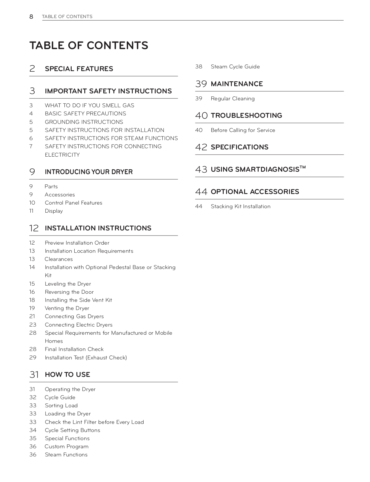
Table of contents
Loading...
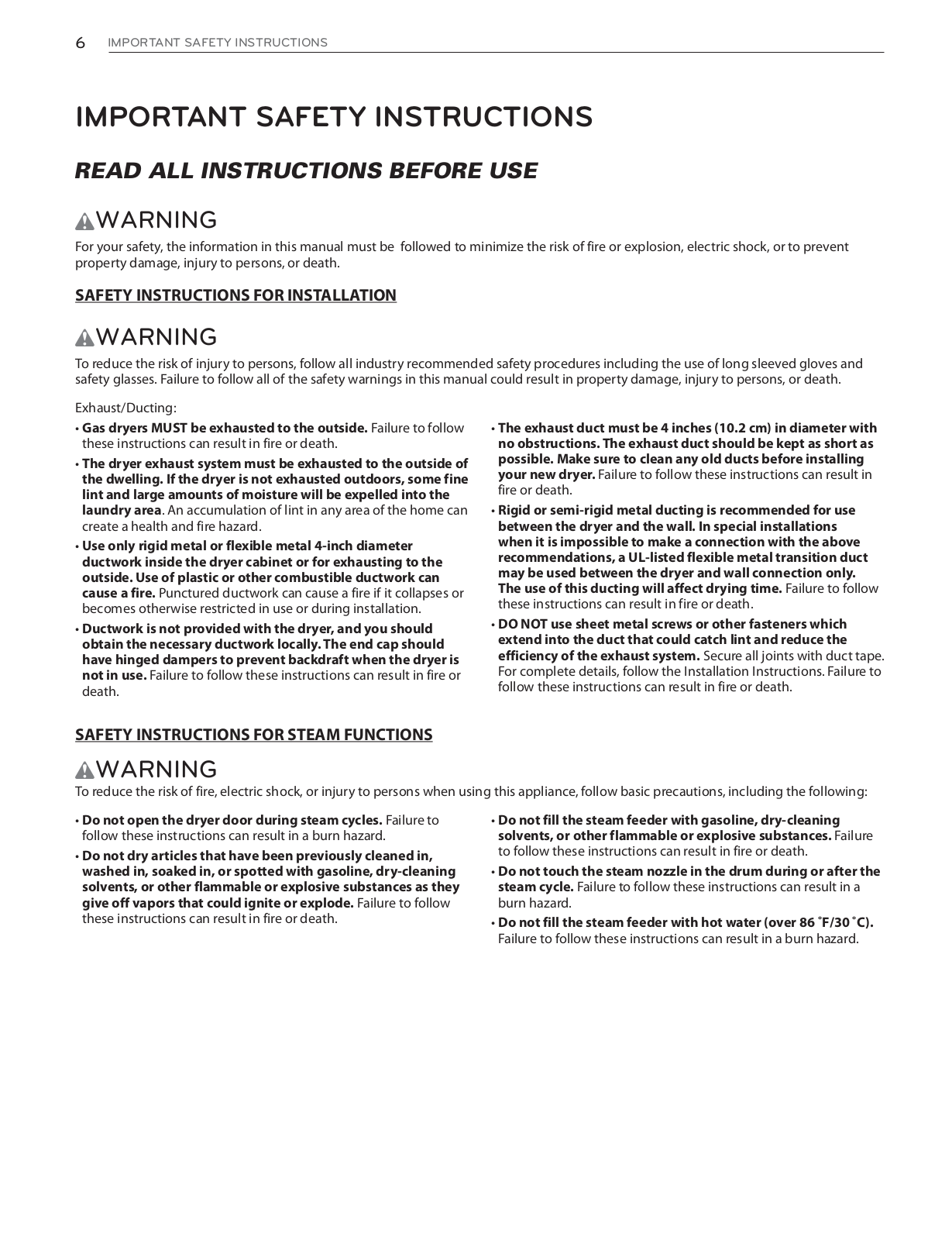
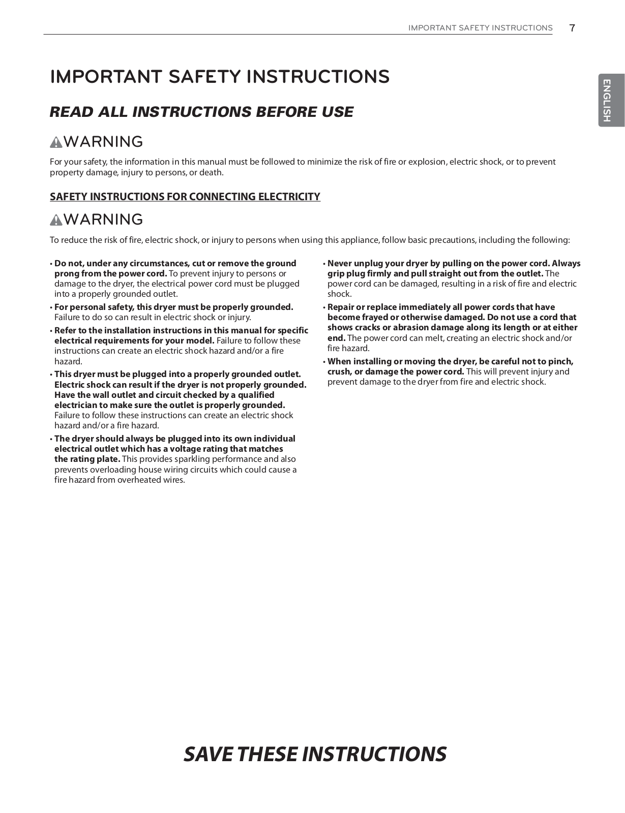
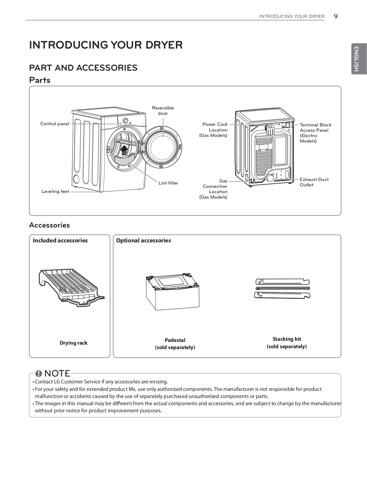
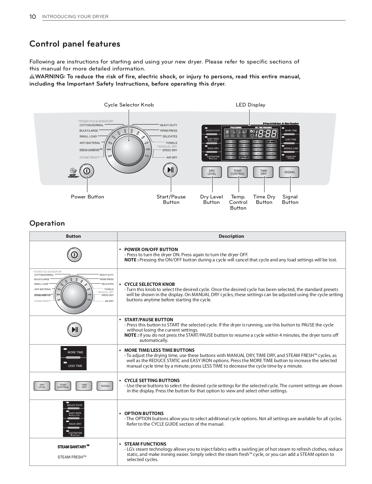
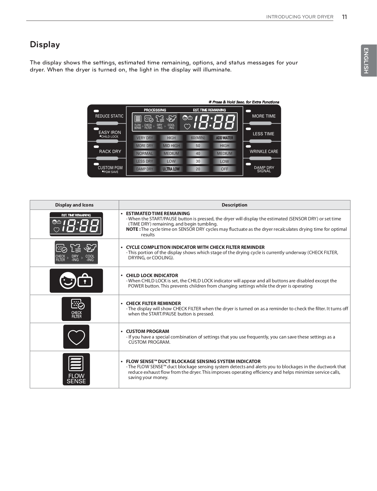
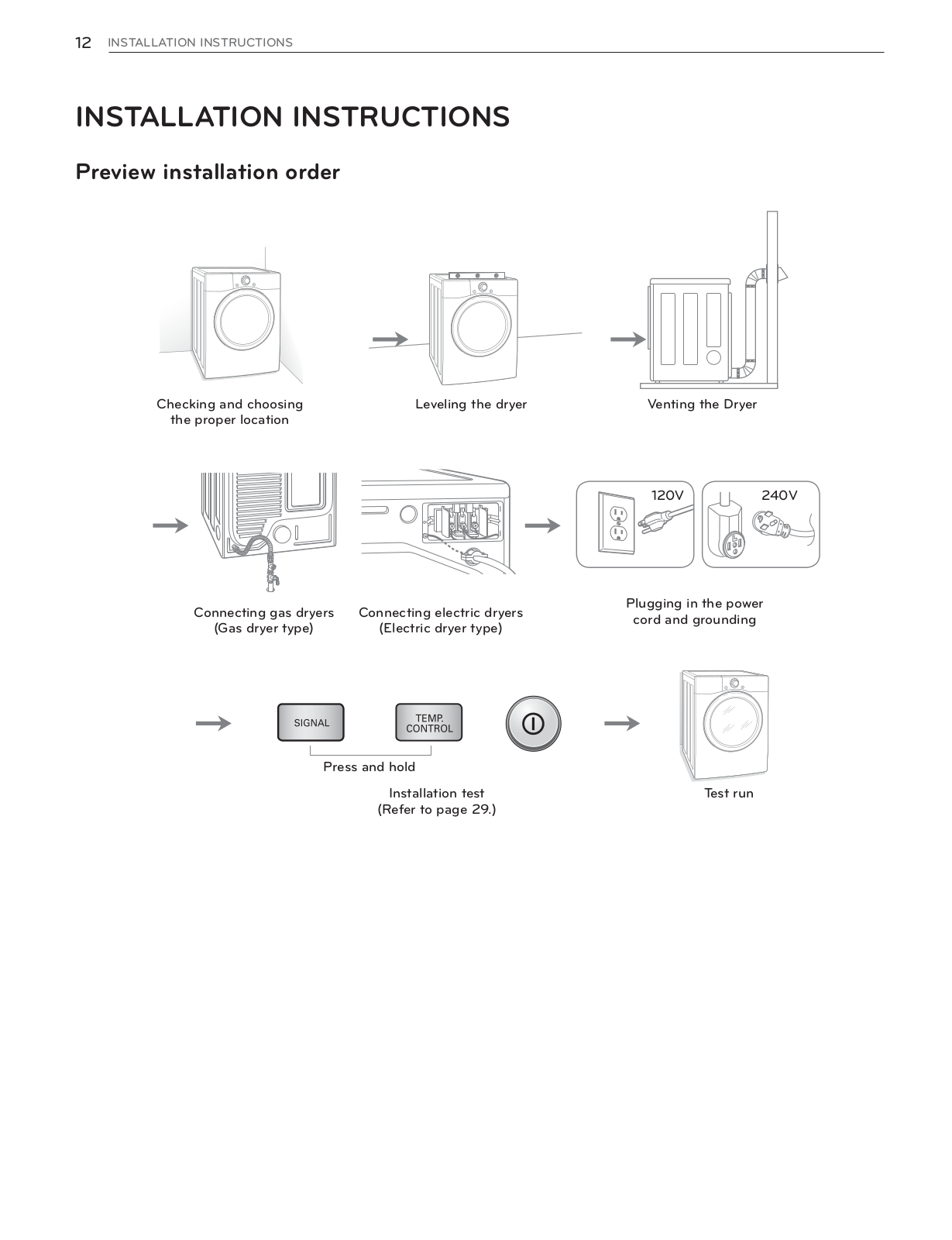
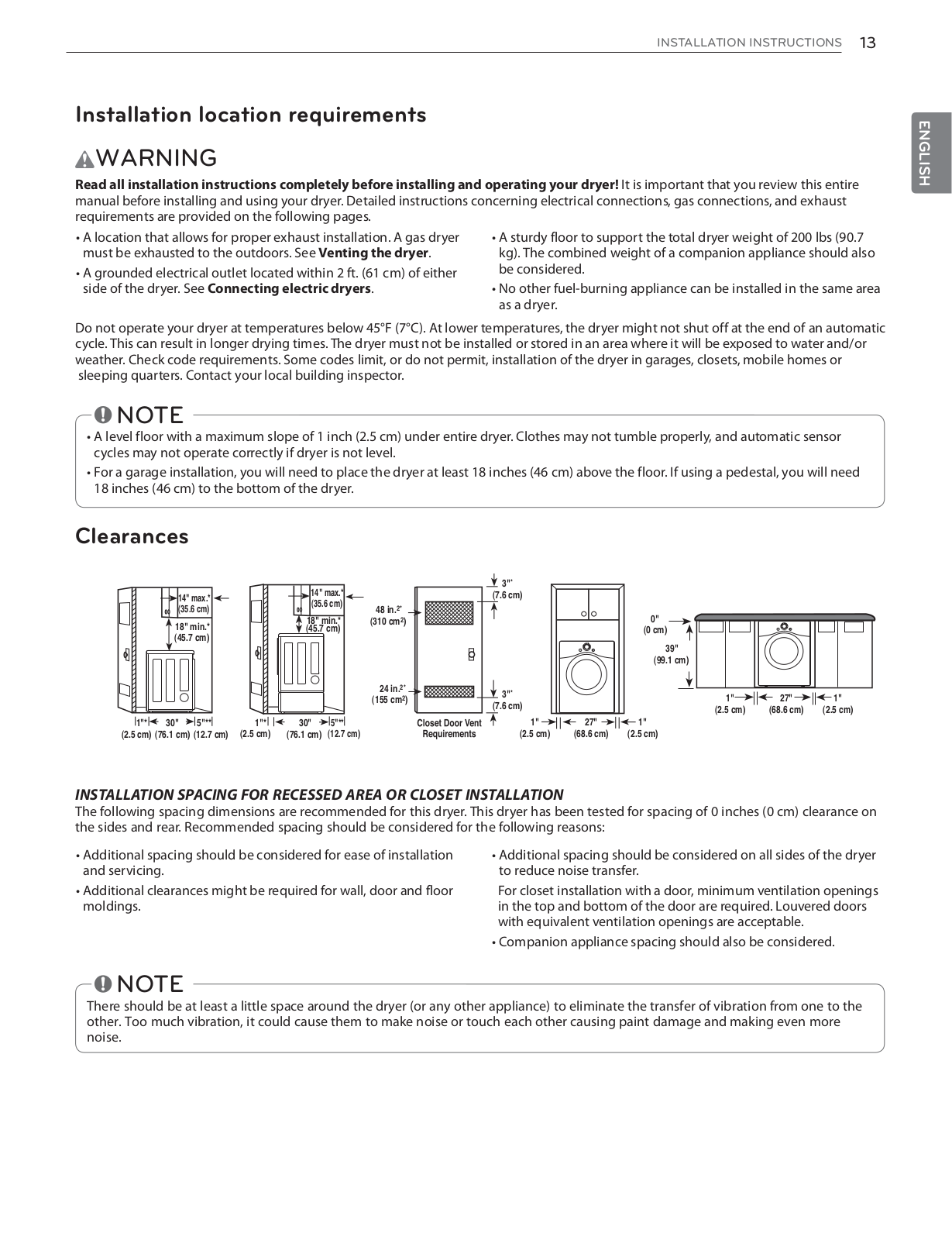
LG DLGX3471V Owner's Manual
...
LG Owner's Manual
Download
Specifications and Main Features
Frequently Asked Questions
User Manual
Download
Loading...
+
70
hidden pages
Unhide
You need points to download manuals.
1 point = 1 manual.
You can buy points or you can get point for every manual you upload.
Buy points
Upload your manuals
 Loading...