

LG DLGX3251W, DLGX3251V, DLGX3251R, DLEX3250W, DLEX3250V Owner’s Manual
...
Life's Good
DR ER
Please read this manuaD carefully before operati
your dryer and retain it for future reference_
DLEX3250 _ DLGX3251 _
P/No. M FL67731008
ng
2 TABLE OF CONTENTS
TABLE OF CONTENTS
3 IMPORTANT SAFETY INSTRUCTIONS
3
WHAT TO DO IF YOU SMELL GAS
4
BASIC SAFETY PRECAUTIONS
4
CALIFORNIA SAFE DRINKING WATER AND TOXIC
ENFORCEMENT ACT
5
GROUNDING INSTRUCTIONS
5
SAFETY INSTRUCTIONS FOR INSTALLATION
6
SAFETY INSTRUCTIONS FOR STEAM FUNCTIONS
7
SAFETY INSTRUCTIONS FOR CONNECTING
ELECTRICITY
8 SPECIAL FEATURES
9 INTRODUCING YOUR DRYER
36
Custom Program
36
Steam Functions
38
Steam Cycle Guide
39
MAINTENANCE
39
Regular Cleaning
4O
TROUBLESHOOTING
4O
Before Calling for Service
SPECIFICATIONS
42
USING SMART DIAGNOSIS TM
43
9 Parts
9 Accessories
10 Control Panel Features
11 Display
12 INSTALLATION INSTRUCTIONS
12 Preview Installation Order
13 Installation Location Requirements
13 Clearances
14 Installation with Optional Pedestal Base
or Stacking Kit
15 Leveling the Dryer
16 Reversing the Door
18 Installing the Side Vent Kit
19 Venting the Dryer
21 Connecting Gas Dryers
23 Connecting Electric Dryers
28 Special Requirements for Manufactured
or Mobile Homes
28 Final Installation Check
29 Installation Test (Duct)
OPTIONAL ACCESSORIES
44
44
Stacking Kit Installation
WARRANTY
46
31 HOW TO USE
31 Operating the Dryer
32 Cycle Guide
33 Sorting Laundry
33 Loading the Dryer
33 Check the Lint Filter Before Every Load
34 Cycle Modifier Buttons
35 Special Functions
IMPORTANT SAFETY INSTRUCTIONS 3
IMPORTANT SAFETY INSTRUCTIONS
READ ALL INSTRUCTIONS BEFORE USE
AWARNING
For your safety, the information in this manual must be followed to minimize the risk of fire, explosion, or electric shock, or to prevent
property damage, injury to persons, or death.
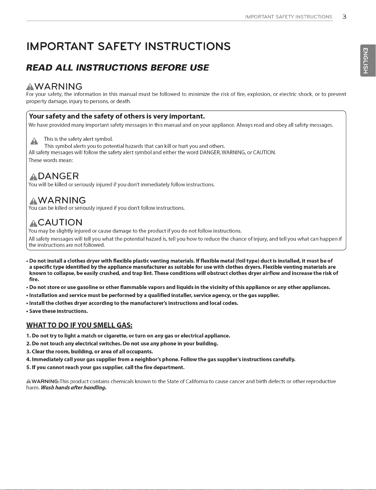
_Your safety and the safety of others is very important.
We have provided many important safety messages in this manual and on your appliance. Always read and obey allsafety messages.
This is the safety alert symbol.
This symbol alerts you to potential hazards that cankill or hurt you and others.
All safety messages will follow the safety alert symbol and either the word DANGER,WARNING,or CAUTION.
These words mean:
ADANGER
You will be killed or seriously injured if you don't immediately follow instructions.
AWARNING
You can be killed or seriously injured if you don't follow instructions.
ACAUTION
You may be slightly injured or causedamage to the product if you do not follow instructions.
All safety messages will tell you what the potential hazard is,tell you how to reduce the chance of injury, and tell you what can happen if
the instructions are not followed.
• Do not install a clothes dryer with flexible plastic venting materials. If flexible metal (foil type) duct isinstalled, it must be of
a specific type identified by the appliance manufacturer assuitable for use with clothes dryers. Rexible venting materials are
known to collapse, be easily crushed, and trap lint. These conditions will obstruct clothes dryer airflow and increase the risk of
fire.
• Do not store or usegasoline or other flammable vapors and liquids in the vicinity of this appliance or any other appliances.
• Installation and service must be performed by aqualified installer, service agency, or the gas supplier.
• Install the clothes dryer according to the manufacturer's instructions and local codes.
• Save these instructions.
WHATTO DO IFYOU SMELL GAS:
1. Do not try to light a match or cigarette, or turn on any gas or electrical appliance.
2. Do not touch any electrical switches. Do not use any phone in your building.
3. Clear the room, building, or area of all occupants.
4. Immediately callyour gas supplier from a neighbor's phone. Follow the gas supplier's instructions carefully.
5. If you cannot reach your gassupplier, call the fire department.
AWARNiNG:This product contains chemicals known to the State of California to cause cancer and birth defects or other reproductive
harm. Wash hands after handling.

4 IMPORTANT SAFETY INSTRUCTIONS
IMPORTANT SAFETY INSTRUCTIONS
READ ALL INSTRUCTIONS BEFORE USE
AWARNING
For your safety, the information in this manual must be followed to minimize the risk of fire, explosion, or electric shock, or to prevent
property damage, injury to persons, or death.
BASIC SAFETY PRECAUTIONS
AWARNING
To reduce the risk of fire, electric shock, or injury to persons when using this appliance, follow basic precautions, including the following:
. Read all instructions before using the dryer.
. Before use, the dryer must be properly installed as described in
this manual.
. Do not place items exposed to cooking oils in your dryer. Items
contaminated with cooking oils may contribute to a chemical
reaction that could cause a load to catch fire.
. Do not dry articles that have been previously cleaned in, washed
in, soaked in, or spotted with gasoline, dry-cleaning solvents, or
other flammable or explosive substances as they give off vapors
that could ignite or explode.
. Do not reach into the dryer if the drum or any other part is
moving.
. Do not repair or replace any part of the dryer or attempt any
servicing unless specifically recommended in this Owner's Manual
or in published user-repair instructions that you understand and
have the skills to carry out.
. Do not tamper with controls.
. Before the dryer is removed from service or discarded, remove the
door to the drying compartment.
. Do not allow children to play on or in the dryer. Close supervision
of children is necessary when the dryer is used near children.
. Do not use fabric softeners or products to eliminate static unless
recommended by the manufacturer of the fabric softener or
product.
. Do not use heat to dry articles containing foam rubber or
similarly textured rubber-like materials.
. Keep the area around the exhaust opening and adjacent
surrounding areas free from the accumulation of lint, dust, and
dirt.
.The interior of the dryer and exhaust vent should be cleaned
periodically by qualified service personnel.
. Do not install or store the dryer where it will be exposed to the
weather.
. Always check the inside of the dryer for foreign objects.
. Clean lint screen before or after each load.
. Do not store plastic, paper, or clothing that may burn or melt
on top of the dryer during operation.
CALIFORNIA SAFE DRINKING WATER AND TOXIC ENFORCEMENT ACT
This act requires the governor of California to publish a list of substances known to the state to cause cancer, birth defects, or other
reproductive harm and requires businesses to warn customers of potential exposure to such substances.
Gas appliances can cause minor exposure to four of these substances, namely benzene, carbon monoxide, formaldehyde, and soot, caused
primarily by the incomplete combustion of natural gas or LPfuels.
Properly adjusted dryers will minimize incomplete combustion. Exposure to these substances can be minimized further by properly
venting the dryer to the outdoors.
IMPORTANT SAFETY INSTRUCTIONS 5
IMPORTANT SAFETY INSTRUCTIONS
READ ALL INSTRUCTIONS BEFORE USE
AWARNING
For your safety, the information in this manual must be followed to minimize the risk of fire, explosion, or electric shock, or to prevent
property damage, injury to persons, or death.
GROUNDING INSTRUCTIONS
This appliance must be grounded. In the event of malfunction
or breakdown, grounding will reduce the risk of electric shock
by providing a path of least resistance for electric current. This
appliance must be equipped with a cord having an equipment-
grounding conductor and a grounding plug.The plug must be
plugged into an appropriate outlet that is properly installed and
grounded in accordance with all local codes and ordinances.
AWARNING
Improper connection of the equipment-grounding conductor can result in a risk of electric shock. Check with a qualified electrician or
service person if you are in doubt that the appliance is properly grounded.
Do not modify the plug provided with the appliance. If it will not fit
the outlet, have a proper outlet installed by a qualified electrician.
This appliance must be connected to a grounded metal, permanent
wiring system or an equipment-grounding conductor must be
run with the circuit conductors and connected to the equipment-
grounding terminal or lead on the appliance.
Electric shock can result if the dryer is not properly grounded.
SAFETY INSTRUCTIONS FOR INSTALLATION
AWARNING
To reduce the risk of fire, electric shock, or injury to persons when using this appliance, follow basic precautions, including the following:
. Properly ground dryer to conform with all governing codes
and ordinances. Follow details in the installation instructions.
Electric shock can result if the dryer is not properly grounded.
. Before use, the dryer must be properly installed as described
in this manual. Electric shock can result if the dryer is not properly
grounded.
. Install and store the dryer where it will not be exposed to
temperatures below freezing or exposed to the weather.
. All repairs and servicing must be performed by an authorized
servicer unless specifically recommended in this Owner's
Guide. Use only authorized factory parts. Failureto follow this
warning can cause serious injury, fire, electric shock, or death.
. Toreduce the risk of electric shock, do not install the dryer in
humid spaces. Failure to follow this warning can cause serious
injury, fire, electric shock, or death.
. Connect to a properly rated, protected, and sized power
circuit to avoid electrical overload. An improper power circuit
can melt, creating electric shock and/or fire hazard.
. Remove all packing items and dispose of all shipping
materials properly. Failure to do so can result in death, explosion,
fire, or burns.
. Place dryer at least 18 inches above the floor for a garage
installation. Failure to do so can result in death, explosion, fire, or
burns.
, Keep all packaging from children. Packaging material can be
dangerous for children. There is a risk of suffocation.
. Do not install near another source of heat such as a stove
or oven. Failure to follow this warning can cause product
deformation, smoke and fire.
. Do not place candles, smoking materials, or other flammables
on top of the product. Dripping wax, smoke, or fire can result.
. Remove all protective vinyl film from the product. Failure to do
so can cause product damage, smoke or fire.
6 IMPORTANT SAFETY INSTRUCTIONS
IMPORTANT SAFETY INSTRUCTIONS
READ ALL INSTRUCTIONS BEFORE USE
AWARNING
Foryour safety, the information in this manual must be followed to minimize the risk of fire, explosion, or electric shock, or to prevent
property damage, injury to persons, or death.
SAFETY INSTRUCTIONS FOR INSTALLATION
AWARNING
Toreduce the riskof injury to persons, follow all industry recommended safety procedures including the use of long sleeved gloves and
safety glasses.Failure to follow all of the safety warnings in this manual could result in property damage, injury to persons, or death.
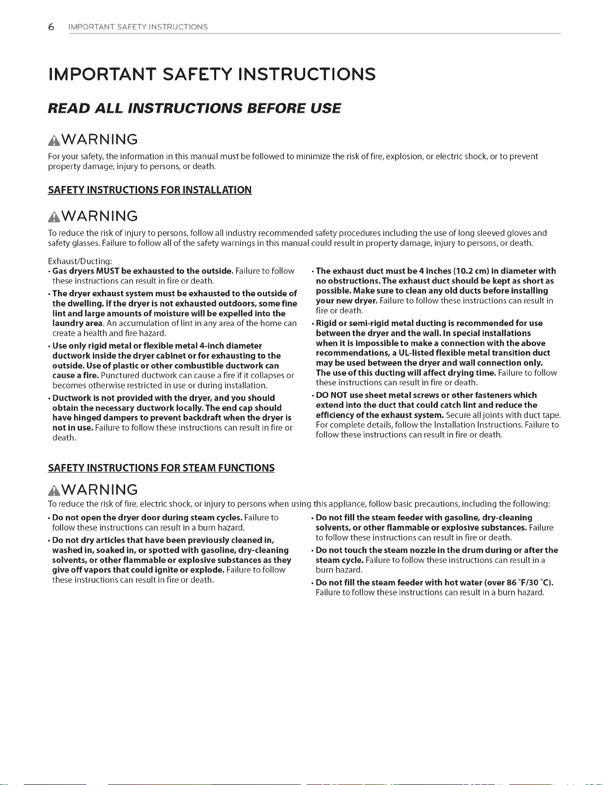
Exhaust/Ducting:
. Gasdryers MUST be exhausted to the outside. Failure to follow
these instructions can result in fire or death.
. The dryer exhaust system must be exhausted to the outside of
the dwelling, if the dryer is not exhausted outdoors, somefine
lint and large amounts of moisture will be expelled into the
laundry area. An accumulation of lint in any area of the home can
create a health and fire hazard.
. Use only rigid metal or flexible metal 4=inch diameter
ductwork inside the dryer cabinet or for exhausting to the
outside. Useof plastic or other combustible ductwork can
causea fire. Punctured ductwork can cause a fire if it collapses or
becomes otherwise restricted in use or during installation.
. Ductwork is not provided with the dryer, and you should
obtain the necessary ductwork locally. The end cap should
have hinged dampers to prevent backdraft when the dryer is
not in use. Failure to follow these instructions can result in fire or
death.
. The exhaust duct must be 4 inches (10.2 cm) in diameter with
no obstructions. The exhaust duct should be kept as short as
possible. Make sure to clean any old ducts before installing
your new dryer. Failureto follow these instructions can result in
fire or death.
. Rigid or semi=rigid metal ducting isrecommended for use
between the dryer and the wall. In special installations
when it is impossible to make a connection with the above
recommendations, a UL=listed flexible metal transition duct
may be used between the dryer and wall connection only.
The use of this ducting will affect drying time. Failureto follow
these instructions can result in fire or death.
. DO NOT use sheet metal screwsor other fasteners which
extend into the duct that could catch lint and reduce the
efficiency of the exhaust system. Secureall joints with duct tape.
For complete details, follow the Installation Instructions. Failure to
follow these instructions can result in fire or death.
SAFETY INSTRUCTIONS FOR STEAM FUNCTIONS
AWARNING
Toreduce the riskof fire, electric shock, or injury to persons when using
. Do not open the dryer door during steam cycles. Failure to
follow these instructions can result in a burn hazard.
. Do not dry articles that have been previously cleaned in,
washed in, soaked in, or spotted with gasoline, dry=cleaning
solvents, or other flammable or explosive substances as they
give offvapors that could ignite or explode. Failureto follow
these instructions can result in fire or death.
this appliance, follow basic precautions, including the following:
Do not fill the steam feeder with gasoline, dry=cleaning
solvents, or other flammable or explosive substances. Failure
to follow these instructions can result in fire or death.
Do not touch the steam nozzle in the drum during or after the
steam cycle. Failure to follow these instructions can result in a
burn hazard.
Do not fill the steam feeder with hot water (over 86 °F/30 °C).
Failure to follow these instructions can result in a burn hazard.
IMPORTANT SAFETY INSTRUCTIONS 7
IMPORTANT SAFETY INSTRUCTIONS
READ ALL INSTRUCTIONS BEFORE USE
AWARNING
Foryour safety,the information in this manual must be followed to minimize the risk of fire, explosion, orelectric shock, or to prevent
property damage, injury to persons, or death.
SAFETY INSTRUCTIONS FOR CONNECTING ELECTRICITY
AWARNING
Toreduce the risk of fire, electric shock, or injury to persons when using this appliance, follow basic precautions, including the following:
. Do not, under any circumstances, cut or remove the ground
prong from the power cord. To prevent injury to persons or
damage to the dryer, the electrical power cord must be plugged
into a properly grounded outlet.
. For personal safety, this dryer must be properly grounded.
Failure to do so can result in electric shock or injury.
. Refer to the installation instructions in this manual for specific
electrical requirements for your model. Failure to follow these
instructions can create an electric shock hazard and/or a fire
hazard.
. This dryer must be plugged into a properly grounded outlet.
Electric shock can result if the dryer is not properly grounded.
Have the wall outlet and circuit checked by a qualified
electrician to make sure the outlet is properly grounded.
Failure to follow these instructions can create an electric shock
hazard and/or a fire hazard.
. The dryer should always be plugged into its own individual
electrical outlet which has a voltage rating that matches the
rating plate. This provides best performance and also prevents
overloading house wiring circuits which could cause a fire hazard
from overheated wires.
. Never unplug your dryer by pulling on the power cord. Always
grip plug firmly and pull straight out from the outlet. The
power cord can be damaged, resulting in arisk of fire and electric
shock.
. Repair or replace immediately all power cords that have
become frayed or otherwise damaged. Do not use a cord that
showscracks or abrasion damage along its length or at either
end. The power cord can melt, creating an electric shock and/or
fire hazard.
. When installing or moving the dryer, be careful not to pinch,
crush, or damage the power cord. This will prevent injury and
prevent damage to the dryer from fire and electric shock.
SAVE THESE INSTRUCTIONS
8 SPECIAL FEATURES
SPECIAL FEATURES
Rotate the cycle selector knob to select the desired dry cycle. Add cycle options or adjust settings with the touch of a button.
The wide-opening door provides easy access for loading and unloading. The door hinge can be reversed to adjust for installation location.
LG's steam technology allows you to inject fabrics with a swirling jet of hot steam to refresh clothes, reduce static, and make ironing
easier. Simply select the STEAM FRESHT'_cycle, or you can add a Steam option to selected cycles.
The FLOW SENSET_duct blockage sensing system detects and alerts you to restrictions in the installed household ductwork that reduce
exhaust airflow through the dryer. If you see the alert: Clean or repair the ducts to remove the restrictions. Keep your ducts clean to help
increase efficiency and reduce long drying times caused by blocked ducts.
Should you experience any technical difficulty with your dryer, it has the capability of transmitting data via your telephone to the
Customer Information Center. The call center agent records the data transmitted from your machine and uses it to analyze the issue,
providing a fast and effective diagnosis (refer to page 43).
INTRODUCING YOUR DRYER
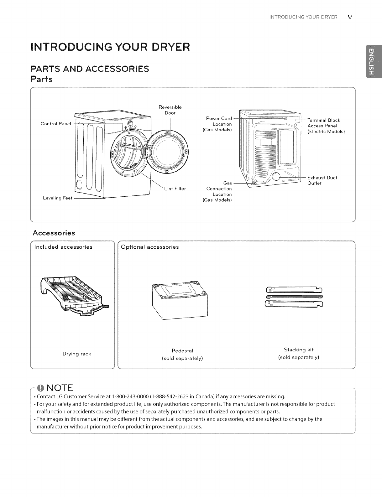
PARTS AND ACCESSORIES
Parts
Reversible
Door
Control Panel
INTRODUCING YOUR DRYER cj
Power Cord
Location
(Gas Models)
Leveling Feet
Accessories
included accessories
Drying rack
_Lint Filter
Optional accessories
(sold separately) (sold separately)
Gas m
Connection
Location
(Gas Models)
Pedestal Stacking kit
'@ NOTE ,,
. Contact LG Customer Service at 1-800-243-0000 (1-888-542-2523 in Canada) if any accessories are missing.
• For your safety and for extended product life, use only authorized components.The manufacturer is not responsible for product I
malfunction or accidents caused by the use of separately purchased unauthorized components or parts. I
• The images in this manual may be different from the actual components and accessories, and are subject to change by the I
...............w!!h :°V n !:..................................................................................................................................................................................................................................................................................................................................................................................................................................................................................................................../
10 INTRODUCING YOUR DRYER
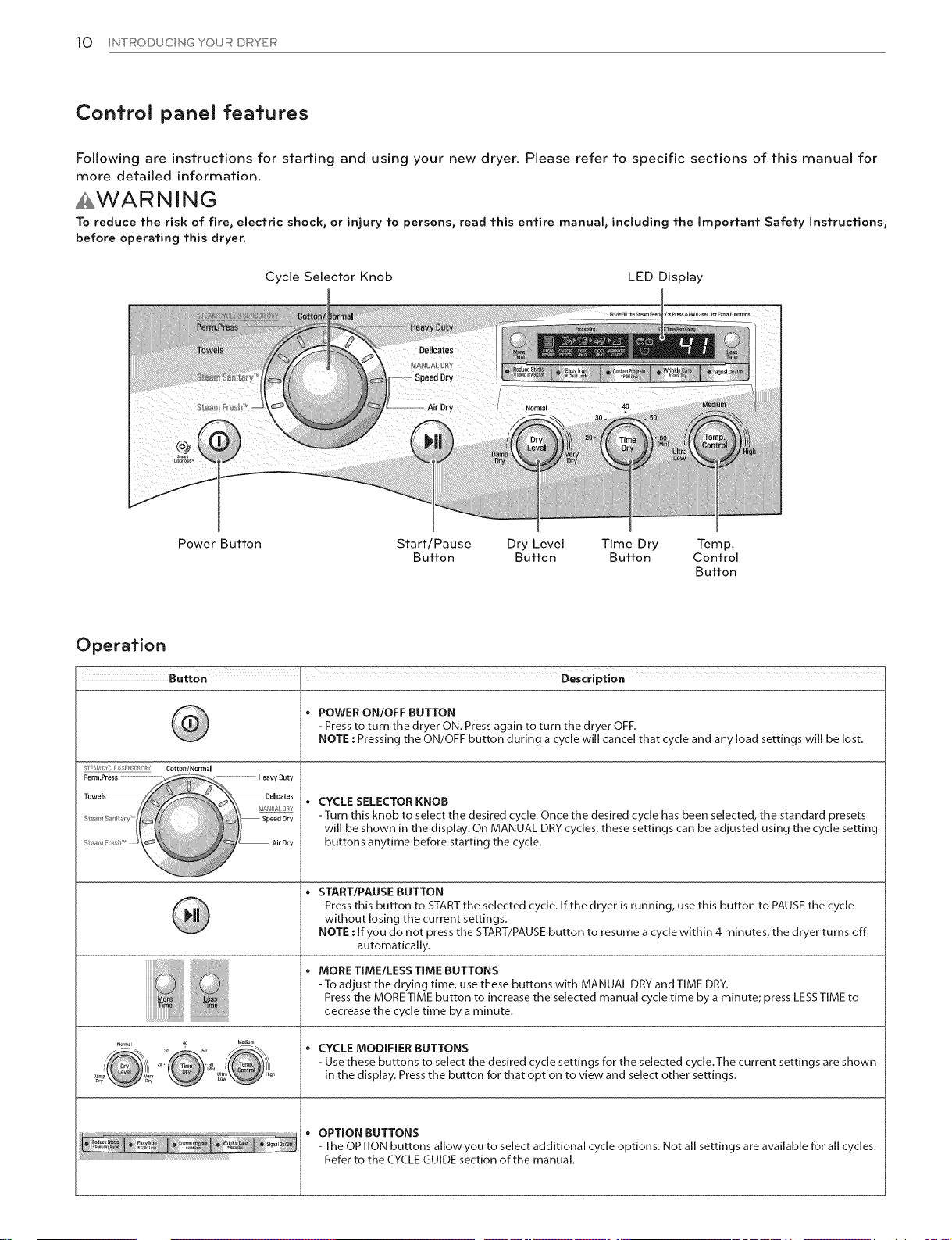
Control panel features
Following are instructions for starting and using your new dryer. Please refer to specific sections of this manual for
more detailed information,
AWARNING
To reduce the risk of fire, electric shock, or injury to persons, read this entire manual, including the Important Safety Instructions,
before operating this dryer.
Cycle Selector Knob LED Display
Power Button Start/Pause Dry Level Time Dry Temp.
Operation
ST AK_ :;YCL >,SEllS )rt [?RY Cott0n/N0rmal
i Speed Dry
StY!_1 Air Dry
:?
Button Button Button Control
Button
* POWER ON/OFF BUTTON
- Press to turn the dryer ON. Press again to turn the dryer OFF.
NOTE : Pressing the ON/OFF button during a cycle will cancel that cycle and any load settings will be lost.
* CYCLE SELECTOR KNOB
-Turn this knob to select the desired cycle. Once the desired cycle has been selected, the standard presets
will be shown in the display. On MANUAL DRY cycles, these settings can be adjusted using the cycle setting
buttons anytime before starting the cycle.
START/PAUSE BUTTON
- Press this button to START the selected cycle. If the dryer is running, use this button to PAUSE the cycle
without losing the current settings.
NOTE : If you do not press the START/PAUSE button to resume a cycle within 4 minutes, the dryer turns off
automatically.
MORE TIME/LESS TIME BUTTONS
-To adjust the drying time, use these buttons with MANUAL DRY and TIME DRY.
Press the MORE TIME button to increase the selected manual cycle time by a minute; press LESSTIME to
decrease the cycle time by a minute.
• CYCLE MODIFIER BUTTONS
- Use these buttons to select the desired cycle settings for the selected cycle.The current settings are shown
in the display. Press the button for that option to view and select other settings.
• OPTION BUTTONS
-The OPTION buttons allow you to select additional cycle options. Not all settings are available for all cycles.
Refer to the CYCLE GUIDE section of the manual.
INTRODUCINGYOURDRYEF_11
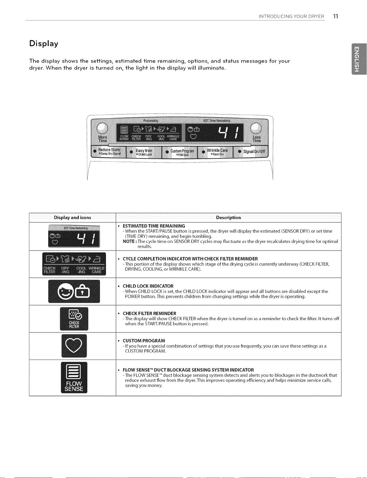
Display
The display shows the settings, estimated time remaining, options, and status messages for your
dryer. When the dryer is turned on, the light in the display will illuminate.
ESTIMATED TIME REMAINING
-When the START/PAUSE button is pressed, the dryer will display the estimated (SENSOR DRY) or set time
(TIME DRY) remaining, and begin tumbling.
NOTE :The cycle time on SENSOR DRY cycles may fluctuate as the dryer recalculates drying time for optimal
results.
• CYCLE COMPLETION INDICATORWITN CHECK FILTER REMINDER
-This portion of the display shows which stage of the drying cycle iscurrently underway (CHECK FILTER,
DRYING, COOLING, or WRINKLE CARE).
CHILD LOCK INDICATOR
-When CHILD LOCK is set, the CHILD LOCK indicator will appear and all buttons are disabled except the
POWER button.This prevents children from changing settings while the dryer is operating.
* CHECK FILTER REMINDER
-The display will show CHECK FILTER when the dryer is turned on as a reminder to check the filter. It turns off
when the START/PAUSE button is pressed.
CUSTOM PROGRAM
- If you have a special combination of settings that you use frequently, you can save these settings as a
CUSTOM PROGRAM.
,, FLOW SENSE TM DUCT BLOCKAGE SENSING SYSTEM INDICATOR
-The FLOW SENSETM duct blockage sensing system detects and alerts you to blockages in the ductwork that
reduce exhaust flow from the dryer.This improves operating efficiency and helps minimize service calls,
saving you money.
12 INSTALLATIONINSTRUCTIONS
INSTALLATION INSTRUCTIONS
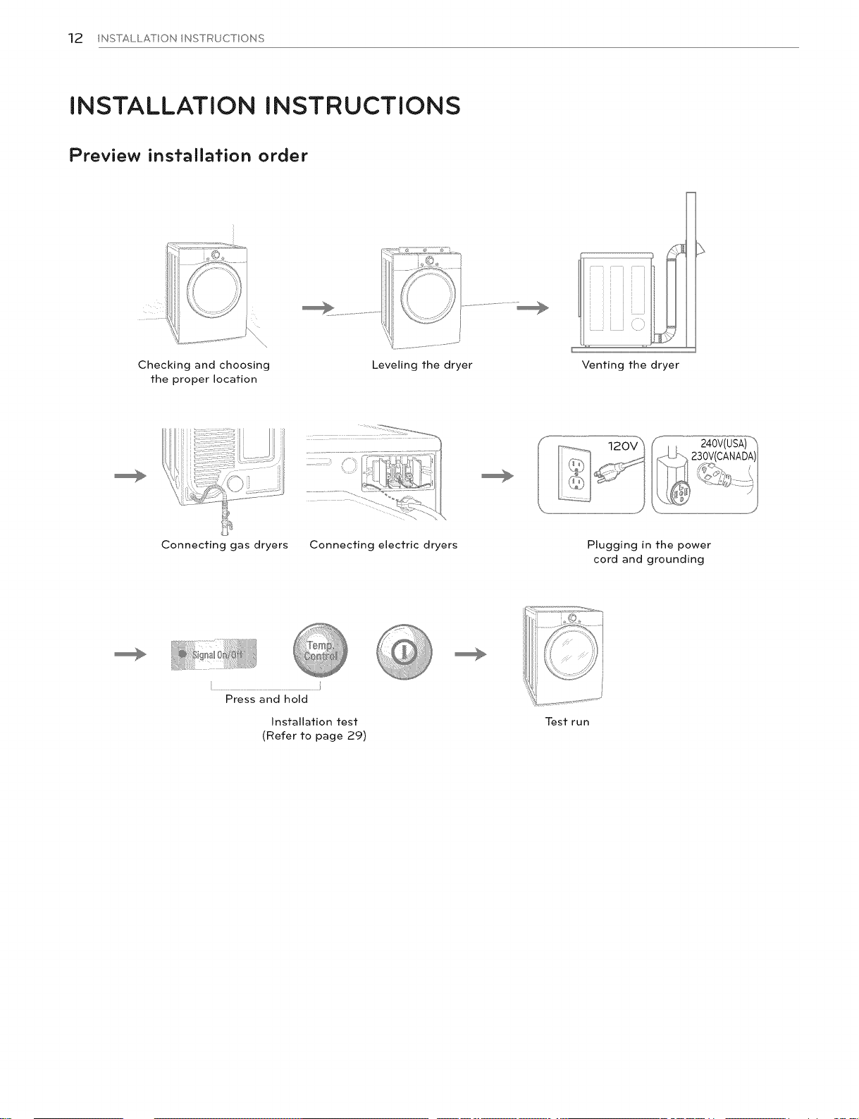
Preview installation order
Checking and choosing
the proper location
Connecting gas dryers Connecting electric dryers Plugging in the power
i
Press and hold
Installation test
(Refer to page 29)
Leveling the dryer Venting the dryer
cord and grounding
Test run
INSTALLATIONINSTRUCTIONS]3
Insfallafion Iocafion requiremenfs
AWARNING
Read all installation instructions completely before installing and operating your dryer! It is important that you review this entire
manual before installing and using your dryer. Detailed instructions concerning electrical connections, gas connections, and exhaust
requirements are provided on the following pages.
, A location that allows for proper exhaust installation. A gas dryer
must be exhausted to the outdoors. See Venting the dryer.
, A grounded electrical outlet located within 2 ft. (61 cm) of either
side of the dryer. See Connecting electric dryers.
Do not operate your dryer at temperatures below 45°F (7°C). At lower temperatures, the dryer might not shut off at the end of an automatic
cycle. This can result in longer drying times. The dryer must not be installed or stored in an area where it will be exposed to water a nd/or
weather. Check code requirements. Some codes limit, or do not permit, installation of the dryer in garages, closets, mobile homes or
sleeping quarters. Contact your local building inspector.
, A sturdy floor to support the total dryer weight of 200 Ibs (90.7
kg).The combined weight of a companion appliance should also
be considered.
, No other fuel-burning appliance can be installed in the same area
as a dryer.
@ NOTE ...............................................................................................................................................................................................................................................................................................................................................................................................................................................................................................................................................................................................................................................................................................................................................................................................................................................................................................................................................................
-The floor must be level, with a maximum slope of 1 inch (2.5 cm) under entire dryer. Clothes may not tumble properly, and automatic
sensor cycles may not operate correctly if the dryer is not level.
• For a garage installation, you will need to place the dryer at least 18 inches (46 cm) above the floor. If using a pedestal, you will need 18
inches (46 cm) to the bottom of the dryer.
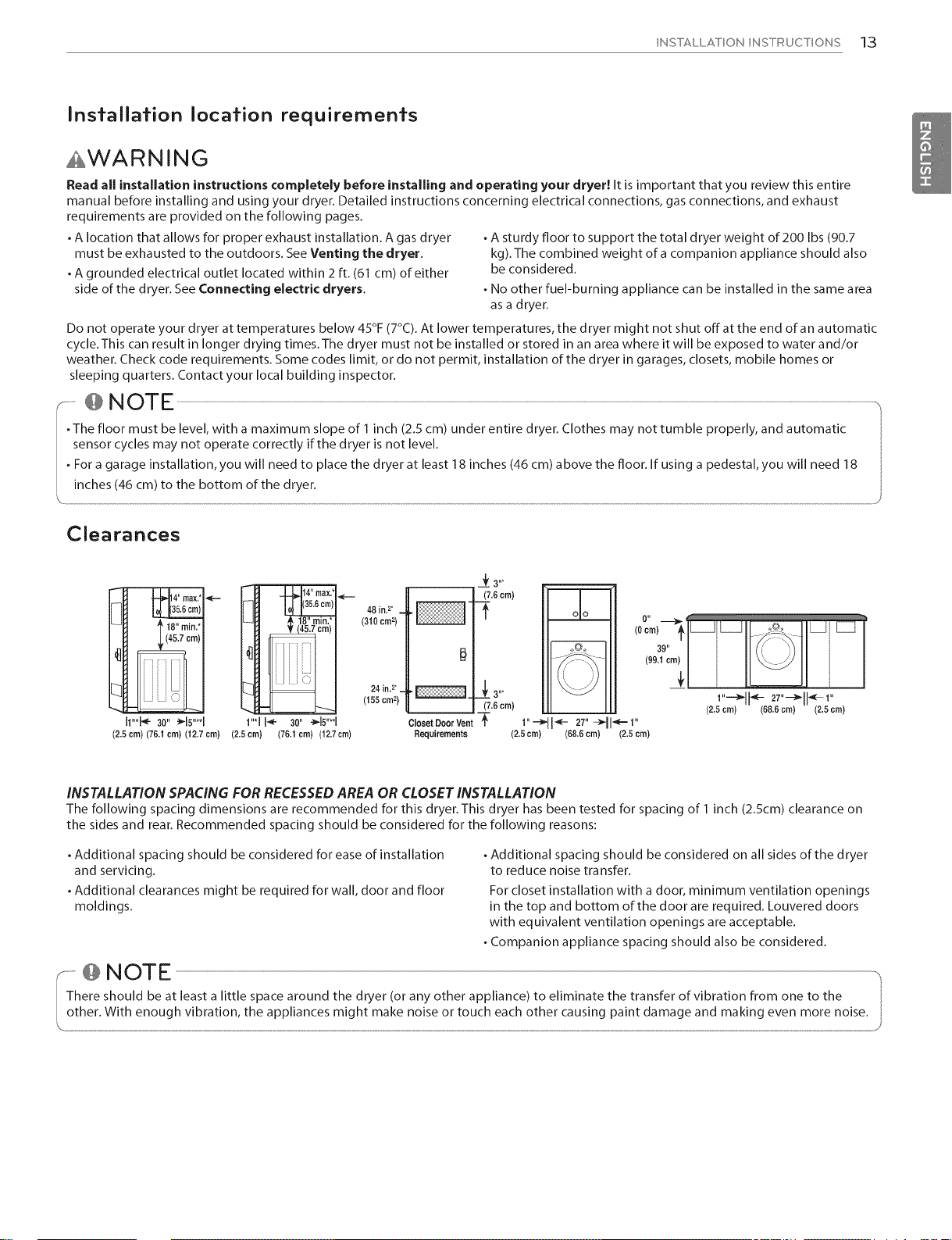
Clearances
_i_14" max.*
I_ |35.8cm)
? 18" rain.*
I (45.7 cm)
I1"*_ 39" _B"q
(2,5 cm) (76.1 cm) (12,7 cm) (2,5 cm)
INSTALLATION SPACING FOR RECESSED AREA OR CLOSET INSTALLATION
The following spacing dimensions are recommended for this dryer. This dryer has been tested for spacing of 1 inch (2.5cm) clearance on
the sides and rear. Recommended spacing should be considered for the following reasons:
. Additional spacing should be considered for ease of installation
and servicing.
, Additional clearances might be required for wall, door and floor
moldings.
1"*1I_ 30"_15"**1
(76,1cm)(12.7crn)
48 in. 2. _
(310 cm 2)
24inF _
(155cm2)
, Additional spacing should be considered on all sides of the dryer
to reduce noise transfer.
For closet installation with a door, minimum ventilation openings
in the top and bottom of the door are required. Louvered doors
with equivalent ventilation openings are acceptable.
, Companion appliance spacing should also be considered.
............@ NOTE -,
There should be at least a little space around the dryer (or any other appliance)to eliminate the transfer of vibration from one to the
14 INSTALLATION INSTRUCTIONS
Insfallafion wifh opfional pedesfal base or slacking kif
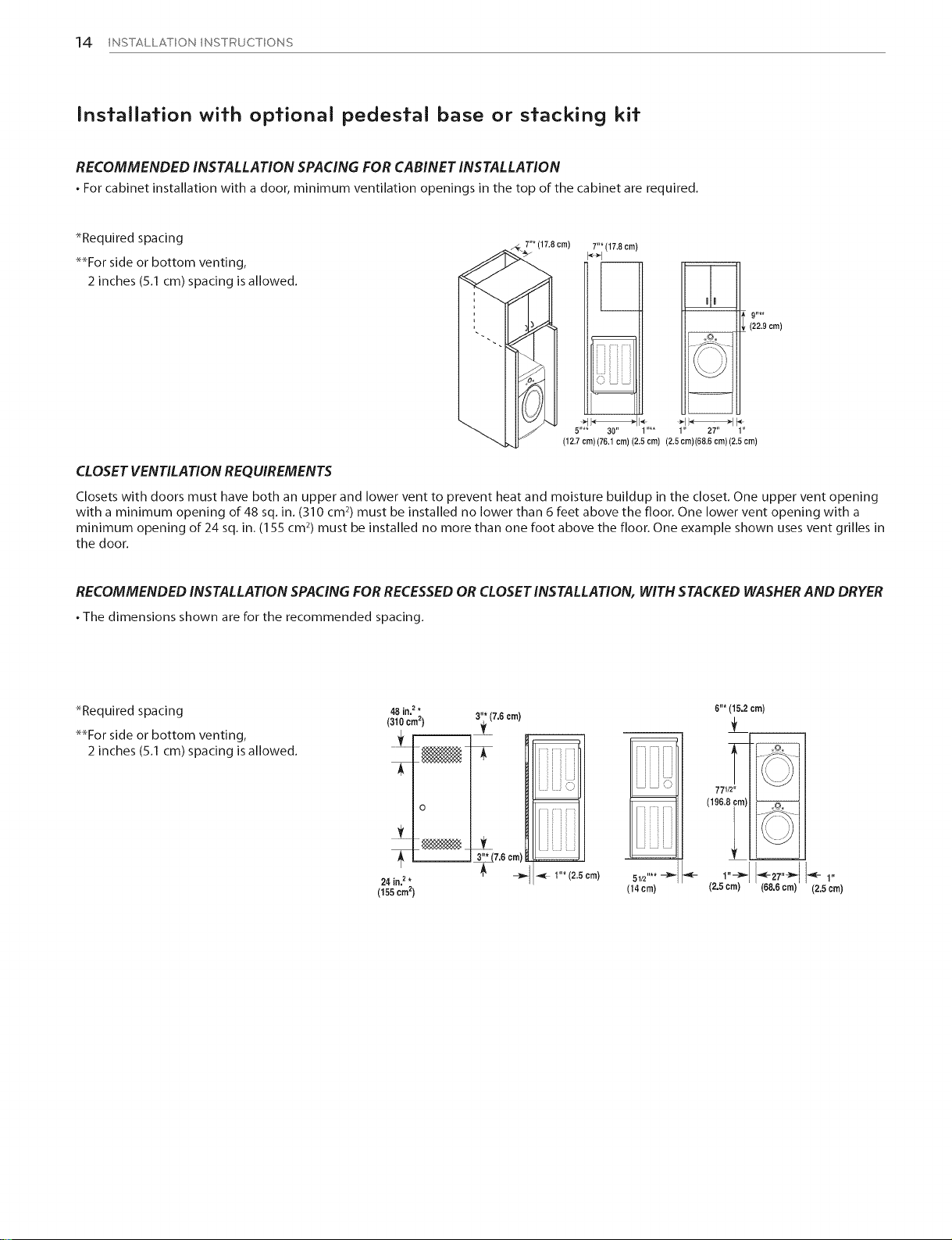
RECOMMENDED INSTALLATION SPACING FOR CABINET INSTALLATION
. For cabinet installation with a door, minimum ventilation openings in the top of the cabinet are required.
_Required spacing
_For side or bottom venting,
'* (17.8cm) 7_*(17.8 cm)
2 inches (5.1 cm) spacing is allowed.
_ (22.9 cm)
\_ -@/
J (12.7cm)(76.1 cm) (2.5 cm) (2.5cm)(68.6 cm)(2.5 cm)
5.... 30" ] .... 1" 27" 1"
CLOSET VENTILATION REQUIREMENTS
Closets with doors must have both an upper and lower vent to prevent heat and moisture buildup in the closet. One upper vent opening
with a minimum opening of 48 sq. in. (310 cm 2)must be installed no lower than 6 feet above the floor. One lower vent opening with a
minimum opening of 24 sq. in. (155 cm2) must be installed no more than one foot above the floor. One example shown uses vent grilles in
the door.
RECOMMENDED INSTALLATION SPACING FOR RECESSED OR CLOSET INSTALLATION, WITH STACKED WASHER AND DRYER
. The dimensions shown are for the recommended spacing.
*Required spacing
**For side or bottom venting,
2 inches (5.1 cm) spacing is allowed.
48 in, 2 * .,
(310 cm2) 3;(7.6
24 in. 2 *
(155crn2)
cm)
7.6 cm
m
1"* (2.5 cm)
! !! !L:
m
51/2"**
(14 cm)
6"*(15.2cm)
771/2"
(196.8 cm) °@--'---7--
\\ J/
(2.5cm) (68.6cm)
(2.5 Cm)
Leveling fhe dryer
INSTALLATION INSTRUCTIONS 15
AWARNING
• To reduce the risk of injury to persons, adhere to all industry
recommended safety procedures including the use of
long sleeved gloves and safety glasses. Failure to follow this
warning can cause serious injury or death.
• The appliances are heavy. Two or more people are required
when installing the dryer. Failure to follow this warning can
cause serious injury or death.
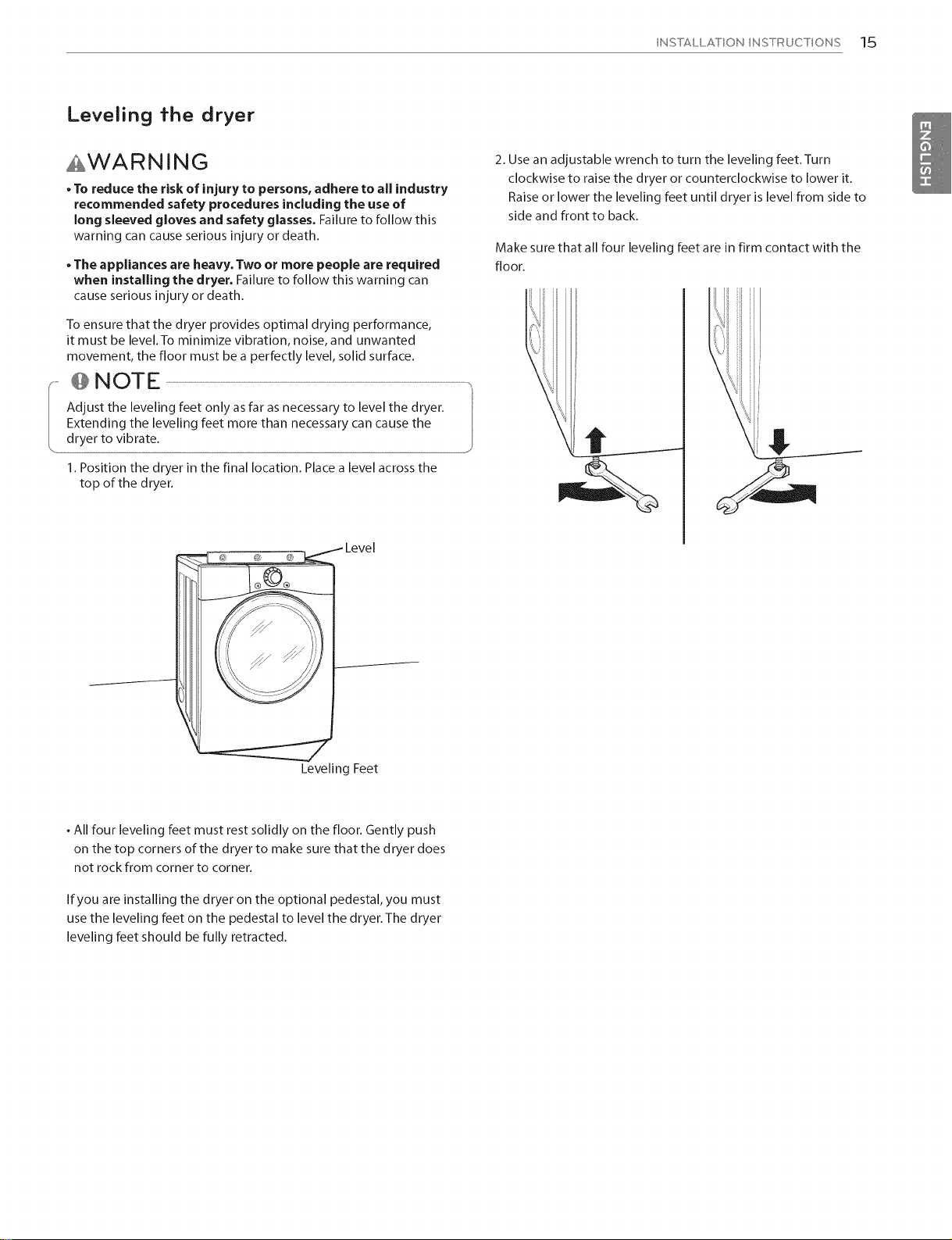
To ensure that the dryer provides optimal drying performance,
it must be level.To minimize vibration, noise, and unwanted
movement, the floor must be a perfectly level, solid surface.
@ NOTE
Adjust the leveling feet only as far as necessary to level the dryer.
Extending the leveling feet more than necessary can cause the
dryer to vibrate.
1. Position the dryer in the final location. Place a level across the
top of the dryer.
_, _-_ Level
2. Use an adjustable wrench to turn the leveling feet.Turn
clockwise to raise the dryer or counterclockwise to lower it.
Raise or lower the leveling feet until dryer is level from side to
side and front to back.
Make sure that all four leveling feet are in firm contact with the
floor.
_________-------
Leveling Feet
. All four leveling feet must rest solidly on the floor. Gently push
on the top corners of the dryer to make sure that the dryer does
not rock from corner to corner.
Ifyou are installing the dryer on the optional pedestal, you must
usethe leveling feet on the pedestal to level the dryer.The dryer
leveling feet should be fully retracted.
1,6 INSTALLATION INSTRUCTIONS
Reversing the door
AWARNING .....................................................................................................................................
• To avoid damage to the dryer or the door, support the
door with a stool or box that fits under the door, or have
an assistant support the weight of the door.
• Always reverse the door BEFORE stacking the dryer on top
of the washer.
• Avoid dropping the door to avoid damage to the door or
the floor.
THE DRYER DOOR ISVERY LARGE AND HEAVY. Failure to follow
the instructions below can result in damage to the dryer,
property damage or injury to persons.
.......................................................................................................................................................................................................................................................................................J
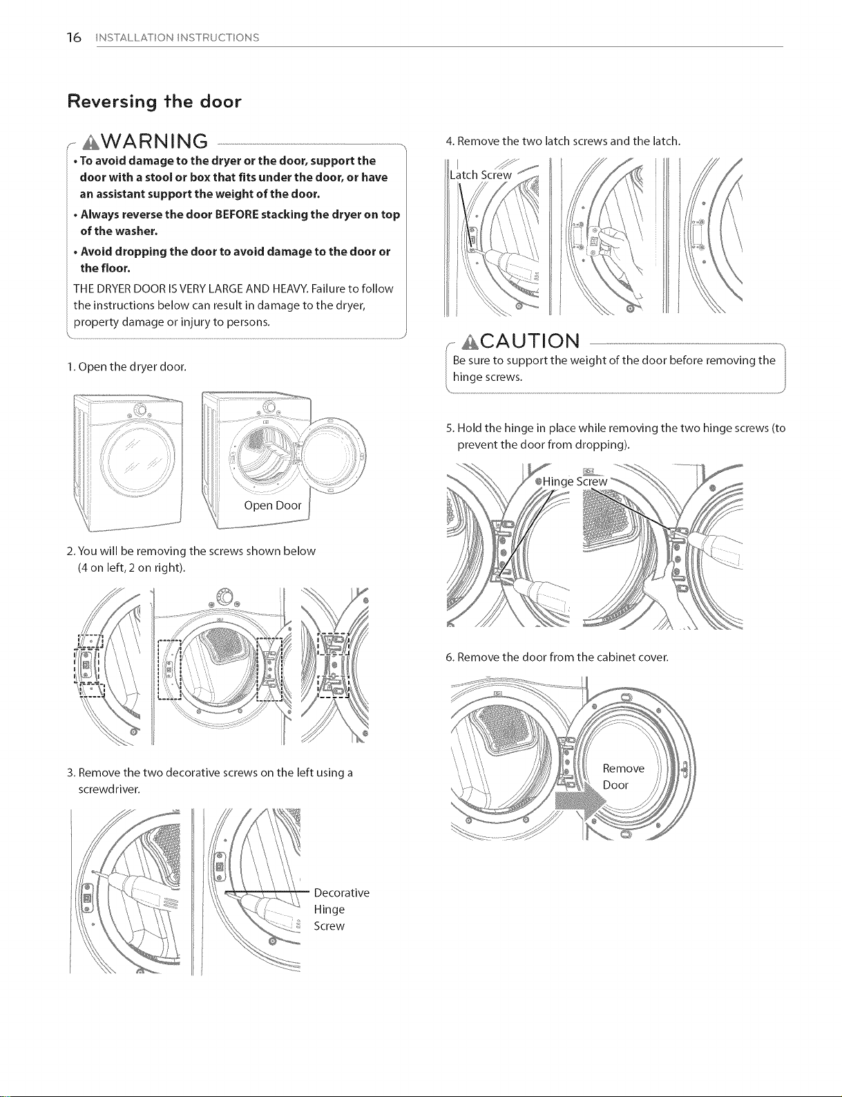
1. Open the dryer door.
Open Door
4. Remove the two latch screws and the latch.
Latch Screw
ACAUTION
Be sure to support the weight of the door before removing the
5. Hold the hinge in place while removing the two hinge screws (to
prevent the door from dropping).
Screw
-,_
2. You will be removing the screws shown below
(4 on left,2 on right).
3. Remove the two decorative screws on the left using a
screwdriver.
Decorative
Hinge
Screw
6. Remove the door from the cabinet cover.
Door
Reversing the door (cont.)
INSTALLATION INSTRUCTIONS 17
£WARNING ..........................................................................................................................................................
• To avoid damage to the dryer or the door, support the
door with a stool or box that fits under the door, or have
an assistant support the weight of the door.
• Always reverse the door BEFORE stacking the dryer on top
of the washer.
• Avoid dropping the door to avoid damage to the door or
the floor.
THE DRYER DOOR ISVERY LARGE AND HEAVY. Failure to follow
the instructions below can result in damage to the dryer,
property damage or injury to persons.
.......................................................................................................................................................................................................................................................................................J
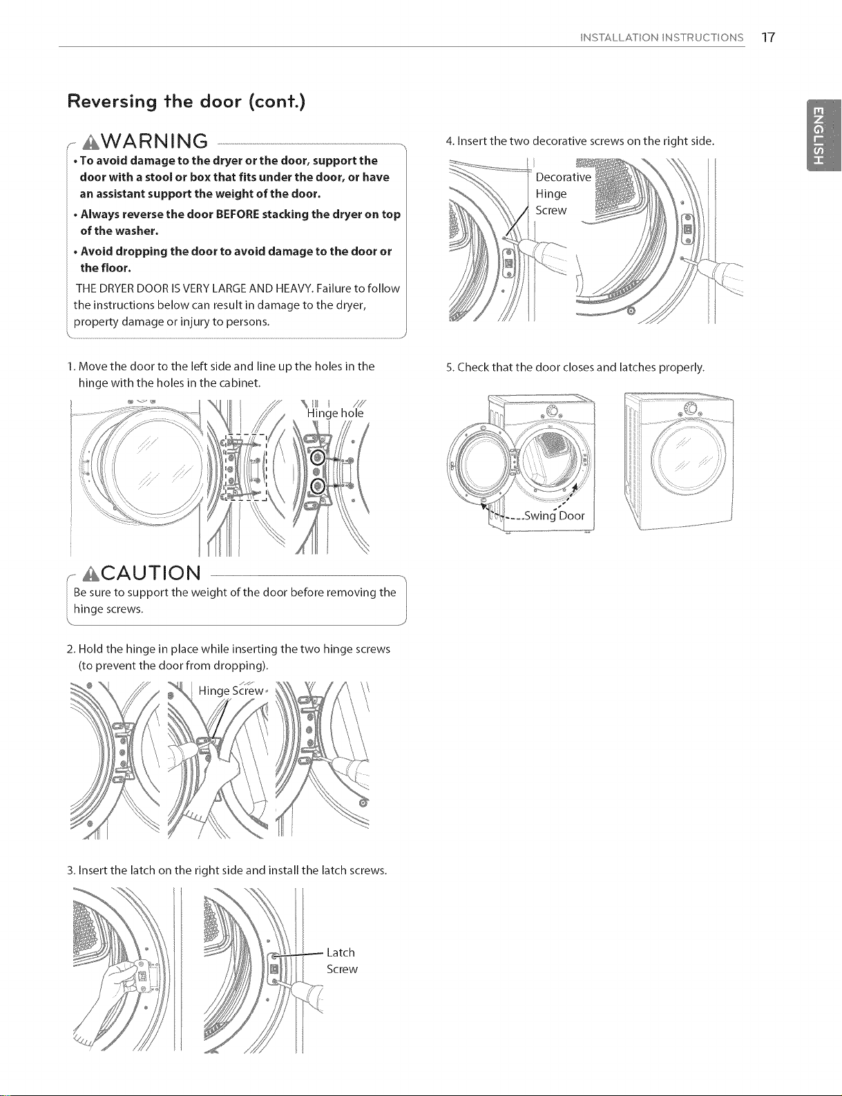
1. Move the door to the left side and line up the holes in the
hinge with the holes in the cabinet.
Hinge hole
4. Insert the two decorative screws on the right side.
Decorative
Hinge
Screw
5. Check that the door closes and latches properly.
ri CAUTION
e sureto support the weight ofthe door beforeremoving the
inge screws.
2, Hold the hinge in place while inserting the two hinge screws
(to prevent the door from dropping),
Hinge Screw_
J
3. Insert the latch on the right side and install the latch screws.
Latch
Screw
18 INSTALLATION INSTRUCTIONS
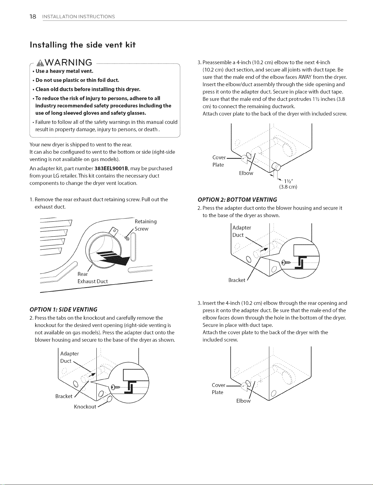
Insfallin9 fhe side venf kif
AWARNING ....................................................................................................................................................................................................................................................................................
• Use a heavy metal vent.
. Do not use plastic or thin foil duct.
• Clean old ducts before installing this dryer.
• To reduce the risk of injury to persons, adhere to all
industry recommended safety procedures including the
use of long sleeved gloves and safety glasses.
• Failure to follow all of the safety warnings in this manual could
result in property damage, injury to persons, or death.
Your new dryer is shipped to vent to the rear.
It can also be configured to vent to the bottom or side (right-side
venting is not available on gas models).
An adapter kit, part number 383EELgOO1B, may be purchased
from your LG retailer. This kit contains the necessary duct
components to change the dryer vent location.
1. Remove the rear exhaust duct retaining screw. Pull out the
exhaust duct.
f
Retaining
3. Preassemble a 4-inch (10.2 cm) elbow to the next 4-inch
(10.2 cm) duct section, and secure all joints with duct tape. Be
sure that the male end of the elbow faces AWAY from the dryer.
Insert the elbow/duct assembly through the side opening and
press it onto the adapter duct. Secure in place with duct tape.
Be sure that the male end of the duct protrudes 11/2inches (3.8
cm) to connect the remaining ductwork.
Attach cover plate to the back of the dryer with included screw.
Plate
OPTION 2: BOTTOM VENTING
2. Press the adapter duct onto the blower housing and secure it
to the base of the dryer as shown.
Adapter
Rear
Exhaust Duct
OPTION 1: SIDE VENTING
2. Press the tabs on the knockout and carefully remove the
knockout for the desired vent opening (right-side venting is
not available on gas models). Press the adapter duct onto the
blower housing and secure to the base of the dryer as shown.
Adapter
Bracket
Knockout
Bracket
3. Insert the 4-inch (10.2 cm) elbow through the rear opening and
press it onto the adapter duct. Be sure that the male end of the
elbow faces down through the hole in the bottom of the dryer.
Secure in place with duct tape.
Attach the cover plate to the back of the dryer with the
included screw.
Plate
INSTALLATION INSTRUCTIONS 19
Venting fhe dryer
AWARNING
To reduce the risk of fire, electric shock, or injury to persons when using this appliance, follow basic precautions, including the following:
. Do not crush or collapse ductwork. Failure to follow these
instructions can result in fire or death
. Do not allow ductwork to rest on or contact sharp objects.
Failure to follow these instructions can result in fire or death
. If connecting to existing ductwork, make sure it is suitable
and clean before installing the dryer. Failure to follow these
instructions can result in fire or death
. Venting must conform to local building codes. Failure to follow
these instructions can result in fire or death.
. Gas dryers MUST exhaust to the outdoors.
Failure to follow these instructions can result in fire or death
. Use only 4=inch (10.2 cm) rigid or flexible metal ductwork
inside the dryer cabinet and for venting outside. Failure to
follow these instructions can result in fire or death
. To reduce the risk of fire, combustion, or accumulation of
combustible gases, DO NOT exhaust dryer air into an enclosed
and unventUated area, such as an attic, wall, ceiling, crawl
space, chimney, gas vent, or concealed space of a building.
Failure to follow these instructions can result in fire or death.
. Toreduce the risk of fire, DO NOTexhaust the dryer with
plastic or thin foil ducting.
Failureto follow these instructions can result in fire ordeath.
. The exhaust duct must be 4 inches (10.2 cm) in diameter with
no obstructions. The exhaust duct should be kept as short as
possible. Make sure to clean any old ducts before installing
your new dryer. Failure to follow these instructionscan result in
fire or death.
. Rigid or semirigid metal ducting is recommended for use
between the dryer and the wall. In special installations
when it is impossible to make a connection with the above
recommendations, a UL=listed flexible metal transition duct
may be used between the dryer and wall connection only.
The useof this ducting will affect drying time. Failureto follow
these instructionscan result in fire or death
. DO NOT use sheet metal screwsor other fasteners which
extend into the duct that could catch lint and reduce the
efficiency of the exhaust system. Secure all joints with duct
tape. Failure to follow these instructionscan result in fire or death
. To maximize operating results, please observe the duct length
limitations noted in the chart on the next page. Failure to
follow these instructions can result in fire or death
. Ductwork is not provided with the dryer. You should obtain
the necessary ductwork locally. The end cap should have
hinged dampers to prevent backdraft when the dryer is not in
use. Failure to follow these instructionscan result in fire or death
. The total length of flexible metal duct shall not exceed8 ft.
(2.4 m)
. In Canada, only those foil=type flexible ducts, if any,
specifically identified for use with the appliance by the
manufacturer shall be used. In the United States, only those
foil type flexible ducts, if any, specifically identified for use with
the appliance by the manufacturer and that comply with the
Outline for Clothes Dryer Transition Duct, Subject 2158A, shall be
used
20 INSTALLATION INSTRUCTIONS
Venting the dryer (cont.)
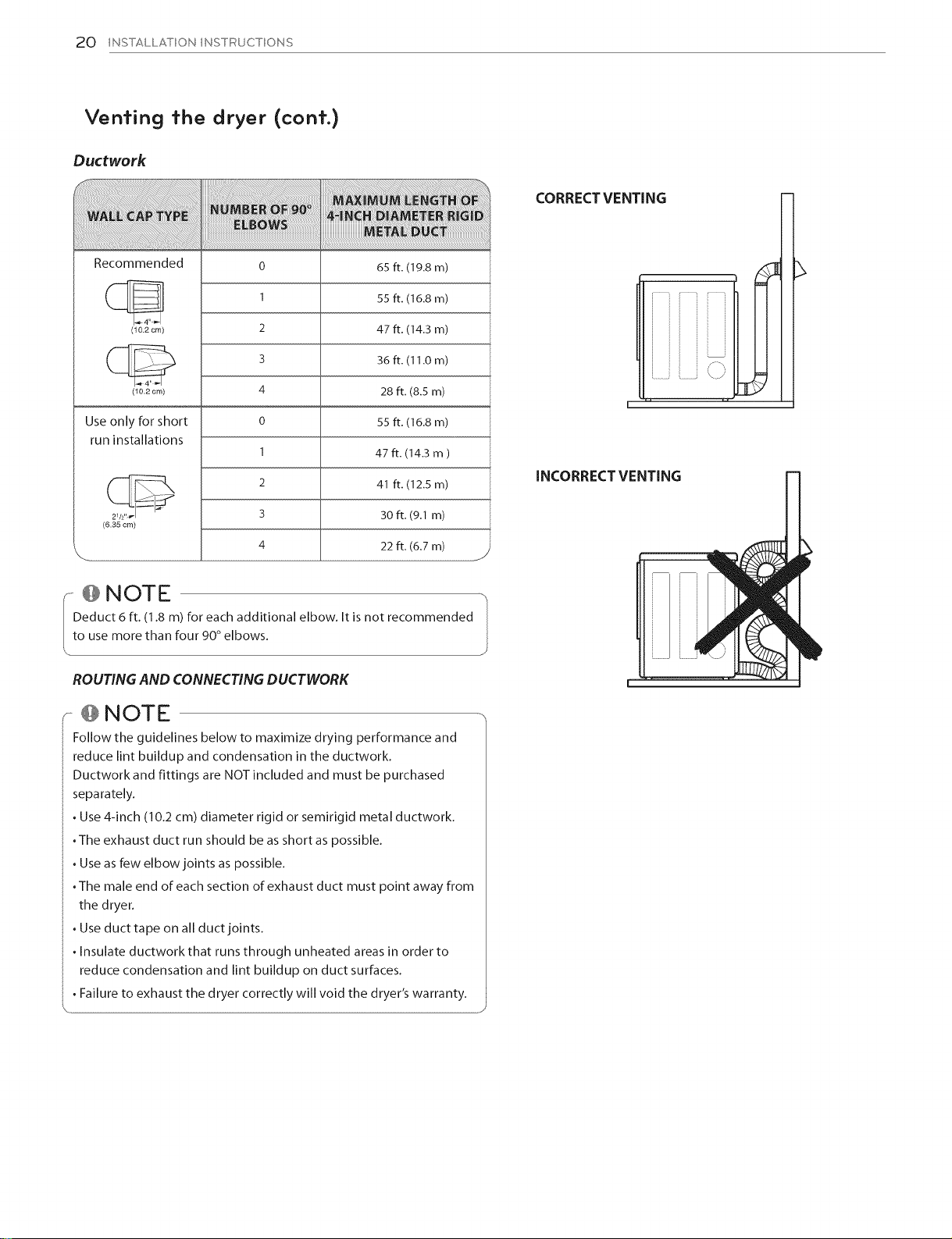
Ductwork
CORRECT VENTING
Recommended
(10.2 cm)
(10.2 cm)
Use only for short
run installations
(6.35 cm)
! Nom
Deduct 6 ft. (1.8 m) for each additional elbow. It is not recommended
0
I
2
3
4
0
I
2
3
4
65 ft. (19.8 m)
55 ft. (16.8 m)
47 ft. (14.3 m)
36 ft. (I 1.0 m)
28 ft. (8.5 m)
55 ft. (16.8 m)
47 ft. (14.3 m )
41 ft. (12.5 m)
30 ft. (9.1 m)
22 ft. (6.7 m)
to use more than four 90°elbows.
ROUTINGAND CONNECTINGDUCTWORK
, @ NOTE -
Follow the guidelines below to maximize drying performance and
reduce lint buildup and condensation in the ductwork,
Ductwork and fittings are NOTincluded and must be purchased
separately.
• Use4-inch (10.2cm) diameter rigid or semirigid metal ductwork,
•The exhaust duct run should be as short aspossible.
• Useasfew elbow joints as possible.
•The male end of each section of exhaust duct must point away from
the dryer.
• Useduct tape on all duct joints,
• Insulate ductwork that runsthrough unheated areas in order to
reduce condensation and lint buildup on duct surfaces.
• Failure to exhaust the dryer correctly will void the dryer's warranty. I
INCORRECT VENTING
J
INSTALLATION INSTRUCTIONS 21
Connecfing gas dryers
AWARNING
To reduce the risk of fire, electric shock, or injury to persons when using this appliance, follow basic precautions, including the following:
. Gas supply requirements:
As shipped from the factory, this dryer is configured for use
with natural gas. It can be converted for use with LP (Liquefied
Propane) gas. Gas pressure must not exceed 13 inches of
water column.
. A qualified service or gas company technician must connect
the dryer to the gas service.
Failure to do so can result in fire, explosion, or death.
. Isolate the dryer from the gas supply system by closing its
individual manual shutoff valve during any pressure testing
of the gas supply. Failure to do so can result in fire, explosion, or
death.
. Supply line requirements:
Your laundry room must have a rigid gas supply line to your
dryer. In the United States, an individual manual shutoff valve
MUST be installed within at least 6 ft. (1.8 rn) of the dryer, in
accordance with the National Fuel Gas Code ANSI Z223.1 or
Canadian gas installation code CSA B149.1. A 1/s- inch NPT
pipe plug must be installed. Failure to do so can result in fire,
explosion, or death
. If using a rigid pipe, the rigid pipe should be 1/2- inch IPS.
If acceptable under local codes and ordinances and when
acceptable to your gas supplier, 3/s- inch approved tubing
may be used where lengths are less than 20 ft. (6.1 rn). Larger
tubing should be used for lengths in excess of 20 ft. (6.1 m).
Failure to do so can result in fire, explosion, or death.
. Connect the dryer to the type of gas shown on the nameplate.
Failure to do so can result in fire, explosion, or death.
. To prevent contamination of the gas valve, purge the gas
supply of air and sediment before connecting the gas supply
to the dryer, Before tightening the connection between the
gas supply and the dryer, purge remaining air until the odor
of gas is detected. Failure to do so can result in fire, explosion, or
death.
. DO NOT use an open flame to inspect for gas leaks. Use a
noncorrosive leak-detection fluid. Failure to do so can result in
fire, explosion, or death.
. Use only a new AGA- or CSA-certified gas supply line with
flexible stainless steel connectors. Failure to do so can result in
fire, explosion, or death.
. Securely tighten all gas connections. Failure to do so can result
in fire, explosion, or death.
. DO NOT attempt any disassembly of the dryer; any
disassembly requires the attention and tools of an authorized
and qualified service person or company. Failure to do so can
result in fire, explosion, or death.
. Use a pipe-joint compound that is insoluble in Liquefied
Petroleum (LP) gas on all pipe threads. Failure to do so can
result in fire, explosion, or death.
. In the Commonwealth of Massachusetts:
This product must be installed by a licensed plumber or gas fitter.
When using ball-type gas shut off valves, they shall be
T-handle-type. A flexible gas connector, when used, must not
exceed 3 feet.
Electrical requirements for gas models only
AWARNING
To reduce the risk of fire, electric shock, or injury to persons when using this appliance, follow basic precautions, including the following:
. Do not, under any circumstances, cut or remove the third
(ground) prong from the power cord. Failure to follow this
warning can result in fire, explosion, or death.
. For personal safety, this dryer must be properly grounded.
Failure to follow this warning can result in fire, explosion, or death.
. The power cord of this dryer is equipped with a 3-prong
(grounding) plug which mates with a standard 3=prong
(grounding) wall outlet to minimize the possibility of electric
shock hazard from this appliance. Failure to follow this warning
can result in fire, explosion, or death.
. This dryer must be plugged into a 60 Hz, 120 MAC, grounded
outlet protected by a 15-ampere fuse or circuit breaker. Failure
to follow this warning can result in fire, explosion, or death.
. Where a standard 2-prong wall outlet is encountered, it isyour
personal responsibility and obligation to have it replaced with
a properly grounded 3=prong wall outlet. Failure to follow this
warning can result in fire, explosion, or death.
22 INSTALLATION INSTRUCTIONS
Connecfing gas dryers (conf.)
WARNING
To reduce the risk of fire, electric shock, or injury to persons when
using this appliance, follow basic precautions, including the
following:
. Installation and service must be performed by a qualified
installer, service agency, or the gas supplier. Failure to follow
this warning can result in fire, explosion, or death.
. Use only a new stainless steel flexible connector and a new
AGA-certified connector. Failure to do so can result in fire,
explosion, or death.
. Agas shutoff valve must be installed within 6 ft. (1.8 m} of
the dryer. Failure to do so can result in fire, explosion, or death.
, The dryer is configured for Natural Gas when shipped from
the factory. Make sure that the dryer is equipped with the
correct burner orifice for the type of gas being used (Natural
Gas or Liquefied Petroleum). Failure to do so can result in fire,
explosion, or death.
. If necessary, the correct orifice (for the LP orifice kit, order
part number 383EEL3002D) should be installed by a
qualified technician and the change should be noted on the
dryer. Failure to do so can result in fire, explosion, or death.
. All connections must be in accordance with local codes and
regulations. Failure to follow this warning can result in fire,
explosion, or death.
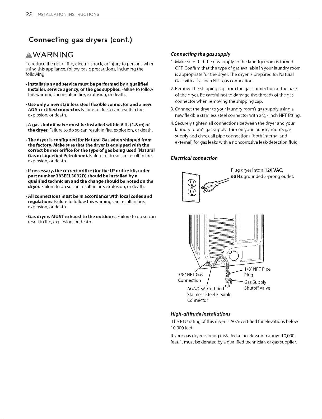
Connecting the gas supply
1. Make sure that the gas supply to the laundry room is turned
OFF. Confirm that the type of gas available in your laundry room
is appropriate for the dryer. The dryer is prepared for Natural
Gas with a 3/8- inch NPT gas connection.
2. Remove the shipping cap from the gas connection at the back
of the dryer. Be careful not to damage the threads of the gas
connector when removing the shipping cap.
3. Connect the dryer to your laundry room's gas supply using a
new flexible stainless steel connector with a 3/8- inch NPT fitting.
4. Securely tighten all connections between the dryer and your
laundry room's gas supply.Turn on your laundry room's gas
supply and check all pipe connections (both internal and
external) for gas leaks with a noncorrosive leak-detection fluid.
Electrical connection
Plug dryer into a 120VAC,
60 Hz grounded 3-prong outlet.
. Gas dryers MUST exhaust to the outdoors. Failure to do so can
result in fire, explosion, or death.
1/8" NPT Pipe
3/8" NPT Gas Plug
Connection Gas Supply
AGA/CSA-Certified ShutoffValve
Stainless Steel Flexible
Connector
High-altitude installations
The BTU rating of this dryer is AGA-certified for elevations below
10,000 feet.
If your gas dryer is being installed at an elevation above 10,000
feet, it must be derated by a qualified technician or gas supplier.
Connecting electric dryers
INSTALLATION INSTRUCTIONS 23
AWARNING
To help prevent fire, electric shock, serious injury, or death, the
wiring and grounding must conform to the latest edition of the
National Electrical Code, ANSI/NFPA70 and all applicable local
regulations. Pleasecontact a qualified electrician to check your
home's wiring and fuses to ensure that your home has adequate
electrical power to operate the dryer.
Electrical requirements for electric models only
AWARNING
To reduce the risk of fire,electric shock, or injury to persons when
using this appliance, follow basic precautions, including the
following:
. This dryer must be connected to a grounded metal,
permanent wiring system, or an equipment-grounding
conductor must be run with the circuit conductors and
connected to the equipment-grounding terminal or lead on
the dryer. Failure to do so can result in fire, explosion, or death.
. The dryer has its own terminal block that must be connected
to a separate 240 VAC, 60-Hertz, single-phase circuit, fused
at 30 amperes (the circuit must be fused on both sides of the
line). ELECTRICAL SERVICE FOR THE DRYER SHOULD BE OF
THE MAXIMUM RATE VOLTAGE LISTED ON THE NAMEPLATE.
DO NOT CON NECT DRYER TO 110=, 115=, OR 120-VOLT
CIRCUIT. Failure to follow these instructions can result in fire,
explosion, or death.
AWARNING
To reduce the risk of fire,electric shock, or injury to persons when
using this appliance, follow basic precautions, including the
following:
• Do not modify the plug and internal wire provided with the
dryer.
•The dryer should be connected to 4=hole outlet.
• If it does not fit the outlet, a proper outlet will need to be
installed by a qualified electrician.
AWARNING
To reduce the risk of fire,electric shock, or injury to persons when
using this appliance, follow basic precautions, including the
following:
. Any installation in a manufactured or mobile home must
comply with the Manufactured Home Construction and
Safety Standards Title 24 CFR, Part 3280 or Standard CAN/
CSAZ240 MH and local codes and ordinances.
. A 4=wire connection is required for all mobile and
manufactured home installations, as well as all new
construction after January 1, 1996. Failure to follow these
requirements can result in fire, explosion, or death.
. if branch circuit to dryer is 15 ft. (4.5 m) or less in length,
use UL (Underwriters Laboratories) listed No.=10AWG wire
(copper wire only), or asrequired by local codes. If over
1Sft. (4.5 m), use UL=listed No.=8AWG wire (copper wire
only), or as required by local codes. Allow sufficient slack in
wiring so dryer can be moved from its normal location when
necessary. Failureto do socan result in fire, explosion, or death.
. The power cord (pigtail) connection between wall receptade
and dryer terminal block iS NOT supplied with dryer. Type of
pigtail and gauge of wire must conform to local codes and
with instructions on the following pages. Failure to follow
these instructions can result in fire, explosion, or death.
. A 4=wire connection is required for all mobile and
manufactured home installations, as well as all new
construction after January 1, 1996. A 4-wire connection must
be used where local codes do not permit grounding through
the neutral wire. Failure to do so can result in fire, explosion, or
death.
24 INSTALLATION INSTRUCTIONS
Connecting electric dryers (cont.)
USA only
.......£WARNING ..................................................................................................................................
. Connect the power cord to the terminal block. Connect
each power cord wire to the terminal block screw that has
the same colored wire. For example, connect the black
power cord wire to the terminal block screw with the black
wire. Failure to follow these instructions may result in a
short, overload, fire or death.
. Grounding through the neutral conductor is prohibited
for: (1) new branch=circuit installations, (2) mobile homes,
(3) recreational vehicles, and (4) areas where local codes
prohibit grounding through the neutral conductor.
Four-wire connection for electric dryers:
Power cord
. A 4-wire connection is required for all mobile and manufactured
home installations, as well as all new construction after January 1,
1996.
. A UL-listed strain relief is required.
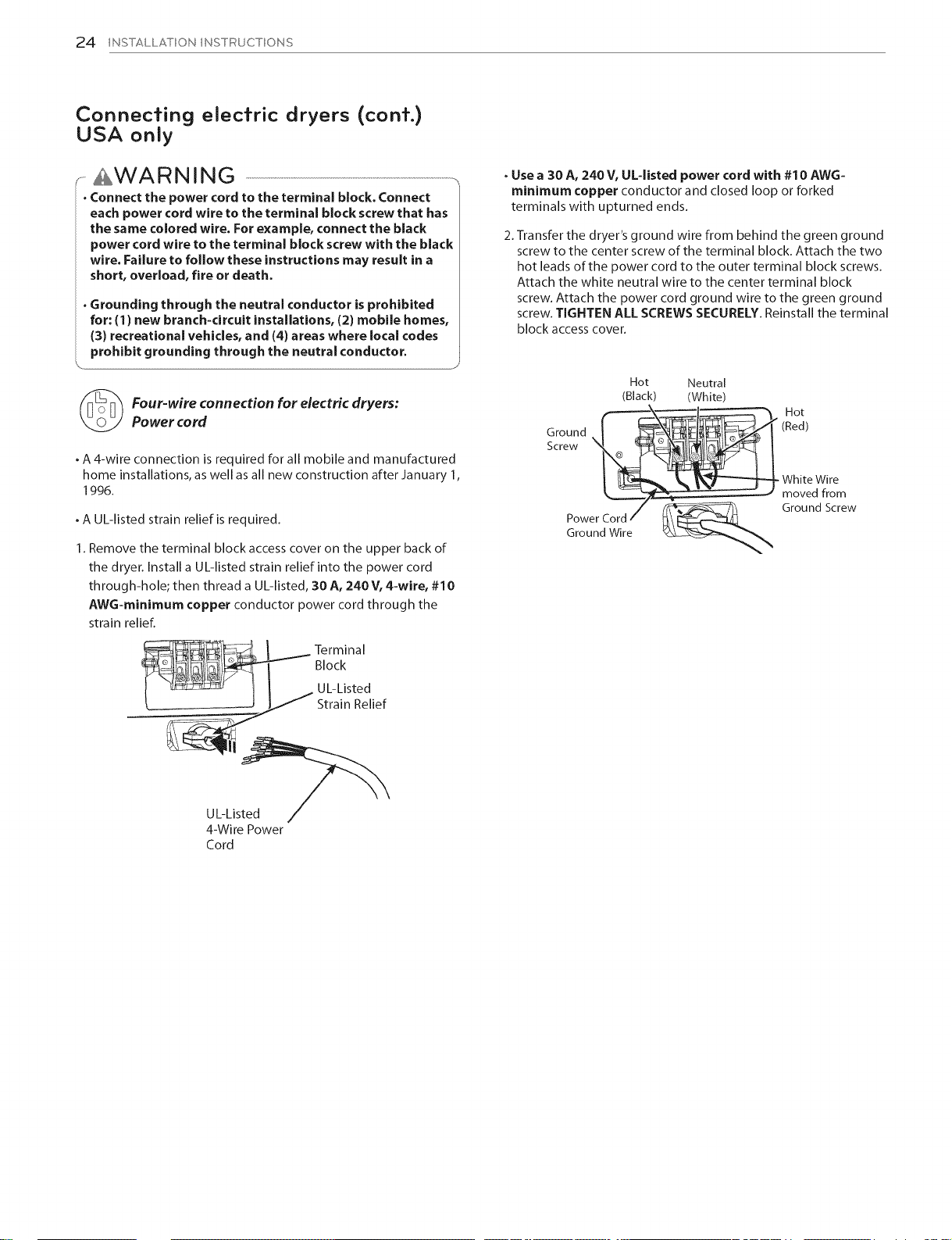
1. Remove the terminal block access cover on the upper back of
the dryer. Install a UL-listed strain relief into the power cord
through-hole; then thread a UL-listed, 30 A, 240 V, 4=wire, #10
AWG-minimum copper conductor power cord through the
strain relief.
S
. Use a 30 A, 240 V, OL=listed power cord with #10 AWG-
minimum copper conductor and closed loop or forked
terminals with upturned ends.
2. Transfer the dryer's ground wire from behind the green ground
screw to the center screw of the terminal block. Attach the two
hot leads of the power cord to the outer terminal block screws.
Attach the white neutral wire to the center terminal block
screw. Attach the power cord ground wire to the green ground
screw. TIGHTEN ALL SCREWS SECURELY. Reinstall the terminal
block access cover.
Hot Neutral
(Black) (White)
_ Hot
Ground _=--__l__" (Red)
Screw
1_ White Wire
" - moved from
/ _ Ground Screw
Power Cord/ _\
Ground Wire _&_%.
4-Wire Power
Cord
I___--Terminal
Block
UL-Listed
Strain Relief
Connecting electric dryers (cont.)
USA only
INSTALLATION INSTRUCTIONS 25
.......£WARNING ..................................................................................................................................
. Connect the power cord to the terminal block. Connect
each power cord wire to the terminal block screw that has
the same colored wire. For e×ample, connect the black
power cord wire to the terminal block screw with the black
wire. Failure to follow these instructions may result in a
short, overload, fire or death.
. Grounding through the neutral conductor is prohibited
for: (1) new branch=circuit installations, (2) mobile homes,
(3) recreational vehicles, and (4) areas where local codes
prohibit grounding through the neutral conductor.
. J
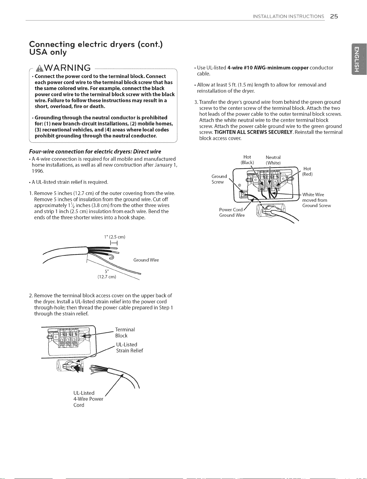
. Use UL-listed 4=wire #10 AWG=minimum copper conductor
cable.
. Allow at least 5 ft. (1.5 m) length to allow for removal and
reinstallation of the dryer.
3.Transfer the dryer's ground wire from behind the green ground
screw to the center screw of the terminal block. Attach the two
hot leads of the power cable to the outer terminal block screws.
Attach the white neutral wire to the center terminal block
screw. Attach the power cable ground wire to the green ground
screw TIGHTEN ALL SCREWS SECURELY Reinstall the terminal
block access cover,
Four-wire connection for electric dryers: Direct wire
. A 4-wire connection is required for all mobile and manufactured
home installations, aswell asall new construction after January 1,
1996.
. A UL-listed strain relief is required.
1. Remove 5 inches (12.7 cm) of the outer covering from the wire.
Remove 5 inches of insulation from the ground wire. Cut off
approximately 11/2inches (3.8 cm) from the other three wires
and strip 1 inch (2.5 cm) insulation from each wire. Bend the
ends of the three shorter wires into a hook shape.
1" (2.5 cm)
Screw '_1 @ _,_,_/_
Hot Neutral
(Black) (White)
Hot
(Red)
•White Wire
moved from
Ground Screw
I--q
__ Ground Wire
(12.57'cm)_
2. Remove the terminal block access cover on the upper back of
the dryer. Install a UL-listed strain relief into the power cord
through-hole; then thread the power cable prepared in Step 1
through the strain relief.
__ erminal
f ",_?" I I UL-Listed
t _-_-_ _ _ Strain Relief
UL-Listed /
4-Wire Power
Cord
Block
2,6 INSTALLATION INSTRUCTIONS
Connecting elec#ic dryers (cont.)
USA only
.......£WARNING ..................................................................................................................................
. Connect the power cord to the terminal block. Connect
each power cord wire to the terminal block screw that has
the same colored wire. For example, connect the black
power cord wire to the terminal block screw with the black
wire. Failure to follow these instructions may result in a
short, overload, fire or death.
. Grounding through the neutral conductor is prohibited
for: (1) new branch=circuit installations, (2) mobile homes,
(3) recreational vehicles, and (4) areas where local codes
prohibit grounding through the neutral conductor.
J
. Use a 30 A, 240 V, UL-listed power cord with # 10 AWG-
minimum copper conductor and closed loop or forked
terminals with upturned ends.
2. Attach the two hot leads of the power cord to the outer
terminal block screws. Attach the neutral wire to the center
terminal block screw. Connect the external ground (if required
by local codes) to the green ground screw. TIGHTEN ALL
SCREWS SECURELY. Reinstall the terminal block access cover.
Hot Neutral
(Black) (White)
Ground ('__1_t
Hot
(Red)
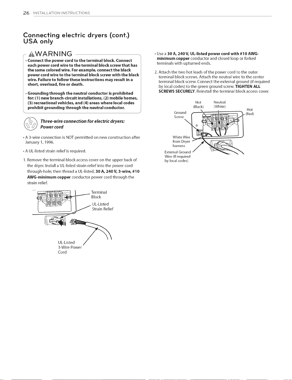
Three-wire connection for electricdryers:
Power cord
. A 3-wire connection is NOT permitted on new construction after
January 1, 1996.
. A UL-listed strain relief is required.
1. Remove the terminal block access cover on the upper back of
the dryer. Install a UL-listed strain relief into the power cord
through-hole; then thread a UL-listed, 30 A, 240V, 3=wire, #10
AWG-minimum copper conductor power cord through the
strain relief.
Screw
WhiteWire -- " "
from Dryer f _f_._
harness/
External Ground / _ __
Wire (if required
by local codes)
UL-Listed
3-Wire Power
Cord
Connecfing elecfric dryers (conf.)
USA only
INSTALLATION INSTRUCTIONS 27
.......AWARNING ...................................................................................................................................,,
. Connect the power cord to the terminal block. Connect
each power cord wire to the terminal block screw that has
the same colored wire. For example, connect the black
power cord wire to the terminal block screw with the black
wire. Failure to follow these instructions may result in a
short, overload, fire or death.
. Grounding through the neutral conductor is prohibited
for: (1) new branch-circuit installations, (2) mobile homes,
(3) recreational vehicles, and (4) areas where local codes
prohibit grounding through the neutral conductor.
J
Three-wire connection for electric dryers: Direct wire
. A 3-wire connection is NOT permitted on new construction after
January 1, 1996.
. A UL-listed strain relief is required.
1. Remove 3_/2inches (8.9 cm) of the outer covering from the wire.
Strip 1 inch (2.5 cm) insulation from each wire. Bend the ends of
the three wires into a hook shape.
1" (2.5 cm)
I-4
. Use UL listed 3=wire#10 AWG-minimum copper conductor
cable.
. Allow at least 5 ft. (1.5 m) length to allow for removal and
reinstallation of the dryer.
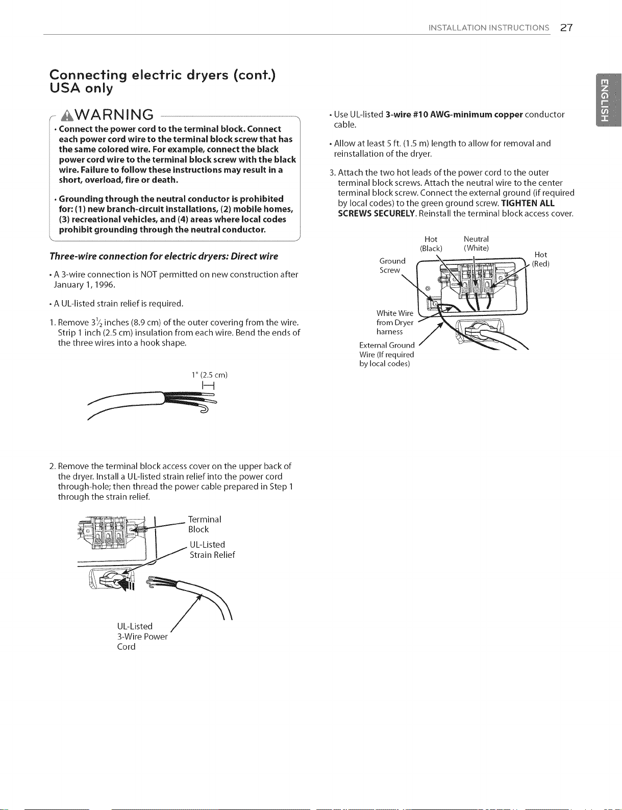
3. Attach the two hot leads of the power cord to the outer
terminal block screws. Attach the neutral wire to the center
terminal block screw. Connect the external ground (if required
by local codes) to the green ground screw. TIGHTEN ALL
SCREWS SECURELY. Reinstall the terminal block access cover.
Hot Neutral
(Black) (White)
Ground f-__l__, (Red)
@ '_
Scre
White
from Dryer f _,__
. Hot
harnessF
External Ground / _ ___%
Wire (If required
by local codes)
2. Remove the terminal block access cover on the upper back of
the dryer. Install a UL-listed strain relief into the power cord
through-hole; then thread the power cable prepared in Step 1
through the strain reliefl
Terminal
Block
UL-Listed
Strain Relief
UL-Listed
3-Wire Power
Cord
28 INSTALLATION INSTRUCTIONS
Special requiremenfs for
manufacfured or mobile homes
Any installation in a manufactured or mobile home must comply
with the Manufactured Home Construction and Safety Standards
Title 24 CFR,Part 3280 or Standard CAN/CSA Z240 MH and
local codes and ordinances. If you are uncertain whether your
proposed installation will comply with these standards, please
contact a service and installation professional for assistance.
, A gas dryer must be permanently attached to the floor.
,The electrical connection for an electric dryer must be a 4-wire
connection. More detailed information concerning the electrical
connection is provided in the section Connecting Electric Dryers.
, To reduce the risk of combustion and fire, the dryer must b e
vented to the outside.
, DO NOT vent the dryer under a manufactured home or mobile
home.
, Electric dryers may be vented to the outside using the back, left,
right, or bottom panel.
, Gas dryers may be vented to the outside using the back, left,
or bottom panel. Gas dryers may not be vented to the outside
using the right side panel because of the burner housing.
,The dryer exhaust duct must be affixed securely to the
manufactured or mobile home structure, and the exhaust duct
must be made of a material that will resist fire and combustion.
It is recommended that you use a rigid or flexible metal duct.
. DO NOT connect the dryer exhaust duct to any other duct, vent,
chimney, or other exhaust duct.
, Make sure the dryer has adequate access to outside fresh air to
ensure proper operation.The opening for outside fresh air must
be at least 25 in 2(163 cm2).
, It is important that the clearance of the duct from any
combustible construction be at least 2 inches (5 cm), and when
venting the dryer to the outdoors, the dryer can be installed with
a clearance of 1 inch (2.5 cm) atthe sides and back of the dryer.
Final insfallafion check
Once you have completed the installation of the dryer and it is
in its final location, confirm proper operation with the following
tests and Installation test (Exhaust check) on the following
page.
Testing dryer heating
GAS MODELS
Closethe dryer door, pressthe ON/OFF button to turn the dryer
on, and start the dryer on aheat setting. When the dryer starts,
the igniter should ignite the main burner.
....@ NOTE ..............................................................................................................................................................................................................................................................................................................................................................................................................
off before the main burner ignites. If this happens, the igniter will
If all air is not purged from the gas line, the gas igniter may turn
reattempt gas ignition after approximately two minutes.
\
ELECTRIC MODELS
Close the dryer door, press the ON/OFF button to turn the dryer
on, and start the dryer on a heat setting. The exhaust air should
be warm after the dryer has been operating for 3 minutes.
Checking airflow
Effective dryer operation requires proper airflow.
The adequacy of the airflow can be measured by evaluating
the static pressure. Static pressure in the exhaust duct can
be measured with a manometer, placed on the exhaust duct
approximately 2 ft. (60.9 cm) from the dryer.
Static pressure in the exhaust duct should not exceed 0.6 inches
(1.5 cm).The dryer should be checked while the dryer is running
with no load.
Checking levelness
Once the dryer is in its final location, recheck the dryer to be sure
it is level. Make sure it is level front to back and side to side, and
that all four leveling feet are firmly on the floor.
, Please be aware that venting materials are not supplied with
the dryer. You should obtain the venting materials necessary for
proper installation.
Installation test (Exhaust check)
INSTALLATION INSTRUCTIONS 29
Once you have completed the installation of the dryer, use this
test to make surethe condition of the exhaust system isadequate
for proper operation of the dryer. This test should be performed
to alert you to any serious problems inthe exhaust system of your
home.
, Your dryer features FLOW SENSErM,an innovative sensing system
that automatically detects blockages and restrictions in dryer
ductwork. Keeping ductwork clean of lint buildup and free of
restrictions allows clothes to dry faster and reduces energy use.
To activate the installation test:
1, Remove the drying rack and literature, and then close the
door.
Do not load anything in the drum for this test, as it may affect
the accuracy of the results.
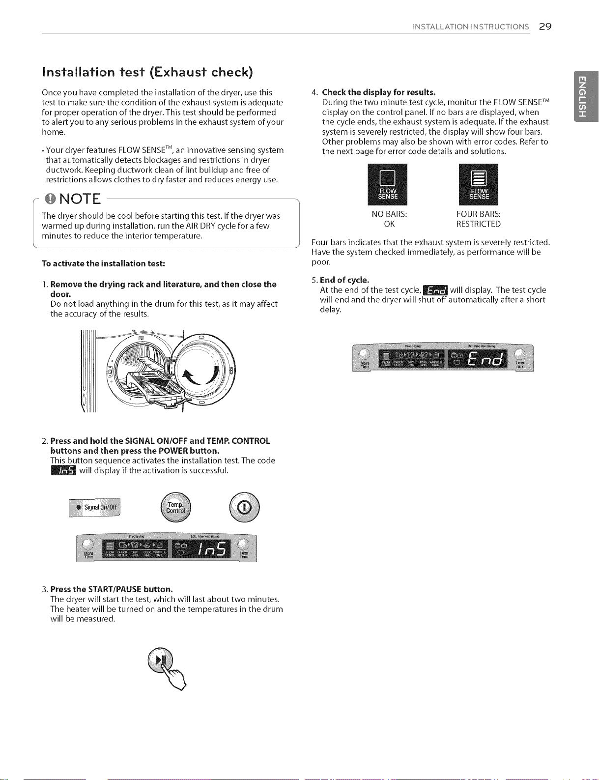
4. Check the display for results.
During the two minute test cycle, monitor the FLOW SENSErM
display on the control panel. If no bars are displayed, when
the cycle ends, the exhaust system is adequate. If the exhaust
system is severely restricted, the display will show four bars.
Other problems may also be shown with error codes. Refer to
the next page for error code details and solutions.
// l/
NO BARS: FOUR BARS:
OK RESTRICTED
Four bars indicates that the exhaust system is severely restricted.
Have the system checked immediately, as performance will be
poor.
5. End of cycle.
At the end of the test cycle, _ will display. The test cycle
will end and the dryer will shut off automatically after a short
delay.
2. Press and hold the SIGNAL ON/OFF and TEMP.CONTROL
buttons and then press the POWER button.
This button sequence activates the installation test. The code
will display if the activation issuccessful.
3. Press the START/PAUSE button.
The dryer will start the test, which will last about two minutes.
The heater will be turned on and the temperatures in the drum
will be measured.
30 INSTALLATION INSTRUCTIONS
Installation test (Exhaust check) (cont.)
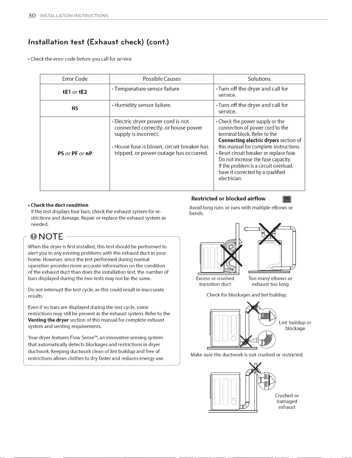
. Check the error code before you call for service
Error Code
tEl ortE2
HS
Temperature sensor failure .Turn off the dryer and call for
Humidity sensor failure. .Turn off the dryer and call for
/} POssible Causes Sol _ions
Electric dryer power cord is not
connected correctly, or house power
supply is incorrect.
House fuse is blown, circuit breaker has
PSor PF or nP
• Check the duct condition
If the test displays four bars, check the exhaust system for re-
strictions and damage. Repair or replace the exhaust system as
needed.
tripped, or power outage has occurred.
......@NOTE ..................................................................................................................................................................................................................................-,
When the dryer is first installed, this test should be performed to
alert you to any existing problems with the exhaust duct in your
home. However, since the test performed during normal
operation provides more accurate information on the condition
of the exhaust duct than does the installation test, the number of
bars displayed during the two tests may not be the same.
Do not interrupt the test cycle, as this could result in inaccurate
results.
service.
service.
. Check the power supply or the
connection of power cord to the
terminal block. Refer to the
Connecting electric dryers section of
this manual for complete instructions.
• Resetcircuit breaker or replace fuse.
Do not increase the fuse capacity.
Ifthe problem isa circuit overload,
haveit corrected bya qualified
electrician.
Restricted or blocked airflow []
Avoid long runs or runs with multiple elbows or
bends.
F
Excess or crushed
transition duct
Check for blockages and lint buildup.
Too many elbows or
exhaust too long
Even if no bars are displayed during the test cycle, some
restrictions may still be present in the exhaust system. Refer to the
Venting the dryer section of this manual for complete exhaust
system and venting requirements.
Your dryer features Flow Sense TM, an innovative sensing system
that automatically detects blockages and restrictions in dryer
ductwork. Keeping ductwork clean of lint buildup and free of
restrictions allows clothes to dry faster and reduces energy use.
Lint buildup or
blockage
Make sure the ductwork is not crushed or restricted.
Crushed or
,i i !,
damaged
exhaust
 Loading...