

LG DLGX2802W, DLGX2802R Owner’s Manual
STEAMDRYERS
USER'SGUIDE&
INSTA[[MiONiNSTRUcTIONS
BefOre beginning installation, read these
instructions carefully. This will simplify installation
and ensure that the drver is installed correctly and
safelv. Leavethese instructions near the drver
after installation for future reference.
STEAMDRYERSTM
Secadorcon vapor
GUIADE[ USUABIOE
INSTBUCCIONESDEINSTA[ACION
Antes de comenzar la instaladon, lea atentamente
estas instruccJones. Esto simplificara la lnstaladon
y asegurara que la secadora est_l instalada
en forma correcta ¥ segura. Conserve estas
instrucciones cerca de la secadora Iuego de la
instalacion para futuras consuItas.
To contact LG Electronics, 24 hours a day,
7 days a week:
1-800-243-0000
Or visit us on the Web at: usJge.com
NQmero telef6nico de LG Electronics, las 24
horas del dia, 7 dias a la semana:
1=800=243=0000
O visitenos en la Web en: us.lge.com
To contact LG Electronics, 24 hours a day,
7 days a week :
1-888-LGCANADA
Or visit us on the Web at : ca.lge.com
Pour contacter LG Electronics, 24 heures
Par jour, 7 jours par semaine :
1-888=LGCANADA
Ou visitez notre site Web a I'addresse "
ca.lge.com
STEAMDP,YEBSMc
Secheusede vapeur
GUIDEDE['UTILISATEURET
DIRECTIVESD'iNSTALLATION
Avant de commencer a installer votre secheuse, lisez
attentJvement ces instructions. Cela simplifiera votre
installation et assurera que la s¢cheuse est Jnstallce
correctement et en toute s¢curit¢. Conservez ces
instructions a proximlt¢ de la secheuse aprcs son
installation, pour reference future.
Models/Modelos/Modeles
Eledric/Elec[rica/Elecl_rique
DLEX2801W
DLEX2801R
DLEX280"I L
protocol P154
Sanitization Performance of Residential
Clothes dryer
Ejecucion de Saneamiento en la zona
resldenclal Secadoras
Niveau de sanitisation des seche-linge
residentiels
P/No. 3828EL3010T
cas/cas/Agaz
DLGX2802W
DLGX2802R
DLGX2802L
INTRODUCTION
IMPORTANT SAFETY INSTRUCTIONS
Basic Safety Precautions ....................................... 3
What to Do if You Smell Gas .................................. 4
California safe drinking water and toxic
enforcement act .................................................... 4
Grounding Instructions ........................................... 5
Safety Instructions for Installation ...................... 5, 6
Safety Instructions for Steam Functions ................ 6
Safety Instructions for Connecting Electricity ....... 7
PARTS AND FEATURES
Special Features ..................................................... 8
Key Parts and Components ................................... 9
INSTALLATION INSTRUCTIONS
IMPORTANT: Read all installation instructions
completely before installing and operating your
dryer! ................................................................... 10
Choose the Proper Location ................................ 10
Clearances ........................................................... 10
Installation With Optional
Pedestal Base or Stacking Kit .............................. 11
Optional Accessories ......................................... 11
Leveling the Dryer ................................................ 12
Reversing the Door Swing .................................... 12
Changing the Dryer Vent Location ....................... 13
Venting the Dryer ............................................ 14, 15
Connecting Gas Dryers .................................. 16, 17
Connecting Electric Dryers ............................. 18-22
Special Requirements for Manufactured
or Mobile Homes .................................................. 23
Final Installation Check ....................................... 23
Flow Check (Duct condition test) ......................... 24
HOW TO USE
Sorting Loads ....................................................... 25
Loading the Dryer ................................................. 25
Check the Lint Filter Before Every Load ............... 25
Control Panel Features ......................................... 26
Cycle Guide .......................................................... 27
The Display ........................................................... 28
Operating the Dryer .............................................. 29
Cycle Setting Buttons .......................................... 29
Cycle Option Buttons .......................................... 30
Special Functions ................................................. 31
Custom Program .................................................. 32
Steam Functions ............................................ 32-34
Steam Cycle Guide .............................................. 34
THANKYOU!
Congratulations on your purchase
and welcome to the LG family. Your
new LG Dryer combines the most
advanced drying sensor technology
with simple operation and high
efficiency. By following the
operating and care instructions
in this manual, your dryer will
provide you with many years of
reliable service.
\,_ ,,.
OPTIONAL ACCESSORIES
Optional Accessories ........................................... 39
Pedestal Installation ....................................... 40, 41
Stacking Kit Installation .................................. 42, 43
Key Dimensions and Specifications ..................... 43
WARRANTY ...................................................44
USER MAINTENANCE INSTRUCTIONS
Regular Cleaning .................................................. 35
TROUBLESHOOTING
Before Calling for Service ............................... 36-38
2
IMPORTANTSAFETYINST UCTIONS
READ ALL iNSTRUCTiONS BEFORE USE
WARNING For your safety,the information in this manual must be
followed to minimize the risk of fire or explosion, electric shock, or to prevent
property damage, personal injury, or loss of life.
r Your Safety and the safety of others is very important.
We have provided many important safety messages in this manual and on your appliance. Always read
and obey all safety messages.
This is the safety alert symbol.
This symbol alerts you to potential hazards that can kill or hurt you and others.
All safety messages will follow the safety alert symbol and either the word DANGER or WARNING.
These words mean:
_DANGI_R: You can be killed or seriously injured if you don't immediately follow instructions.
_WARN|_G, = You can be killed or seriously injured if you don't follow instructions.
All safety messages will tell you what the potential hazard is, tell you how to reduce the chance of
jury, and tell you what can happen if the instructions are not followed.
BASIC SAFETY PRECAUTIONS
WARNING:
appliance, follow basic precautions, including the following:
• Read all instructions before using the dryer.
Before use, the dryer must be properly installed
as described in this manual.
Do not place items exposed to cooking oils in
your dryer. Items contaminated with cooking
oils may contribute to a chemical reaction that
could cause a load to catch fire.
Do not dry articles that have been previously
cleaned in, washed in, soaked in, or spotted
with gasoline, dry-cleaning solvents, or other
flammable or explosive substances as they give
off vapors that could ignite or explode.
• Do not reach into the dryer if the drum or any
other part is moving.
Do not repair or replace any part of the dryer
or attempt any servicing unless specifically
recommended in this Use and Care Guide or
in published user-repair instructions that you
understand and have the skills to carry out.
• Do not tamper with controls.
Before the dryer is removed from service or
discarded, remove the door to the drying
compartment.
To reduce the risk of fire, electric shock, or injury to persons when using this
Do not allow children to play on or in the dryer.
Close supervision of children is necessary when
the dryer is used near children.
Do not use fabric softeners or products to
eliminate static unless recommended by the
manufacturer of the fabric softener or product.
Do not use heat to dry articles containing
foam rubber or similarly textured rubber-like
materials.
Keep area around the exhaust opening and
adjacent surrounding areas free from the
accumulation of lint, dust, and dirt.
The interior of the dryer and exhaust vent
should be cleaned periodically by qualified
service personnel.
Do not install or store the dryer where it will be
exposed to the weather.
Always check the inside of the dryer for foreign
objects.
Clean lint screen before or after each load.
5
i PORTANTSAFETYINST UCTIONS
READ ALL iNSTRUCTiONS BEFORE USE
_WARNING For your safety,the information in this manual must be
followed to minimize the risk of fire or explosion, electric shock, or to prevent
property damage, personal injury, or loss of life.
• Do not store or use gasoline or other
flammable vapors and liquids in the
vicinity of this appliance or any other
appliances.
• installation and service must be
performed by a qualified installer,
service agency, or the gas supplier.
WHAT TO DO IF YOU SMELL GAS:
1. Do not try to light a match or cigarette,
or turn on any gas or electrical
appliance.
2. Do not touch any electrical switches.
Do not use any phone in your building.
3. Clear the room, building, or area of all
occupants.
CALiFORNiA SAFE DRiNKiNG WATER AND TOXIC ENFORCEMENT ACT
This act requires the governor of California to publish a list of substances known to the state to cause
cancer, birth defects, or other reproductive harm and requires businesses to warn customers of potential
exposure to such substances.
Gas appliances can cause minor exposure to four of these substances, namely benzene, carbon monoxide,
formaldehyde, and soot, caused primarily by the incomplete combustion of natural gas or LP fuels.
4. Immediately call your gas supplier
from a neighbor's phone. Follow the
gas supplier's instructions carefully.
5. if you cannot reach your gas
supplier, call the fire department.
Properly adjusted dryers will minimize incomplete combustion. Exposure to these substances can be
minimized further by properly venting the dryer to the outdoors.
4
iMPORTANTSAFETYINST UCTIONS
READ ALL iNSTRUCTiONS BEFORE USE
WARNING For your safety,the information in this manual must be
followed to minimize the risk of fire or explosion, electric shock, or to prevent
property damage, personal injury, or loss of life.
GROUNDING iNSTRUCTiONS
This appliance must be grounded. In the event
of malfunction or breakdown, grounding will
reduce the risk of electric shock by providing
a path of least resistance for electric current.
This appliance must be equipped with a cord
having an equipment-grounding conductor and
a grounding plug. The plug must be plugged into
an appropriate outlet that is properly installed and
grounded in accordance with all local codes and
ordinances.
Do not modify the plug provided with the
appliance. If it will not fit the outlet, have a proper
outlet installed by a qualified electrician.
This appliance must be connected to a grounded
metal, permanent wiring system or an equipment-
grounding conductor must be run with the circuit
conductors and connected to the equipment-
grounding terminal or lead on the appliance.
Electrical shock can result if the dryer is not
properly grounded.
WARN ING - Improper
connection of the equipment=grounding
conductor can result in a risk of electric shock.
Check with a qualified electrician or service
person if you are in doubt as to whether the
appliance is properly grounded.
SAFETY INSTRUCTIONS FOR INSTALLATION
AWARNING: To reduce the risk of fire, electric shock, or injury to persons when using this
appliance, follow basic precautions, including the following:
, Properly ground dryer to conform with all
governing codes and ordinances. Follow
details in the installation instructions. Electrical
shock can result if the dryer is not properly
grounded. ,,
• Before use, the dryer must be properly
installed as described in this manual.
Electrical shock can result if the dryer is not ,
properly grounded.
• install and store the dryer where it will not be
exposed to temperatures below freezing or
exposed to the weather.
, All repairs and servicing must be performed
by an authorized servicer unless specifically
recommended in this Owner's Guide. Use
only authorized factory parts. Failure to follow
this warning can cause serious injury, fire,
electrical shock, or death.
• To reduce the risk of electric shock, do not
install the dryer in humid spaces. Failure to
follow this warning can cause serious injury, fire,
electrical shock, or death.
Connect to a properly rated, protected,
and sized power circuit to avoid electrical
overload. Improper power circuit can melt,
creating electrical shock and/or fire hazard.
Remove all packing items and dispose of all
shipping materials properly. Failure to do so
can result in death, explosion, fire, or burns.
Place dryer at least 18 in. above the floor
for a garage installation. Failure to do so can
result in death, explosion, fire, or burns.
Keep all packaging from children. Packaging
material can be dangerous for children. There is
a risk of suffocation.
Do not install nearby heat item. Such as
stove, cooking oven. Failure to do so can cause
deform, smoke and fire.
Do not place candle and cigarettes on top of
the product. Failure to do so can cause deform,
smoke and fire.
Remove all protective vinyl film from the
product. Failure to do so can cause deform,
smoke and fire.
5
i PORTANTSAFETYINST UCTIONS
READ ALL iNSTRUCTiONS BEFORE USE
WARNING For your safety,the information in this manual must be
followed to minimize the risk of fire or explosion, electric shock, or to prevent
property damage, personal injury, or loss of life.
SAFETY iNSTRUCTiONS FOR iNSTALLATiON
Exhaust/Ducting:
, Gas dryers MUST be exhausted to the
outside. Failure to follow these instructions
can result in fire or death.
• The dryer exhaust system must be exhausted
to the outside of the dwelling, if the dryer is
not exhausted outdoors, some fine lint and
large amounts of moisture will be expelled
into the laundry area. An accumulation of
lint in any area of the home can create a health
and fire hazard.
• Use only rigid metal or flexible metal 4=in.
diameter ductwork inside the dryer cabinet
or for exhausting to the outside. Use of
plastic or other combustible ductwork can
cause a fire. Punctured ductwork can cause
a fire if itcollapses or becomes otherwise
restricted in use or during installation.
Ductwork is not provided with the dryer, and
you should obtain the necessary ductwork
locally. The end cap should have hinged
dampers to prevent backdraft when the dryer
is not in use. Failure to follow these instructions
can result in fire or death.
, The exhaust duct must be 4 in. (10 cm) in
diameter with no obstructions. The exhaust
duct should be kept as short as possible.
Make sure to clean any old ducts before
installing your new dryer. Failure to follow
these instructions can result in fire or death.
• Rigid or semi rigid metal ducting is
recommended for use between the
dryer and the wall. in special installations
when it is impossible to make a connection
with the above recommendations, a UL=
listed flexible metal transition duct may be
used between the dryer and wall connection
only. The use of this ducting will affect drying
time. Failure to follow these instructions can
result in fire or death.
, DO NOT use sheet metal screws or other
fasteners which extend into the duct that
could catch lint and reduce the efficiency
of the exhaust system. Secure all joints with
duct tape. For complete details, follow the
Installation Instructions. Failure to follow these
instructions can result in fire or death.
SAFETY INSTRUCTIONS FOR STEAM FUNCTIONS
WARNING: To reduce the risk of fire, electric shock, or injury to persons when using this
appliance, follow basic precautions, including the following:
Do not open the dryer door during steam
cycles. Failure to follow these instructions can
result in a burn hazard.
Do not dry articles that have been previously
cleaned in, washed in, soaked in, or spotted
with gasoline, dry=cleaning solvents, or other
flammable or explosive substances as they
give off vapors that could ignite or explode.
Failure to follow these instructions can result in
fire or death.
6
• Do not fill the steam feeder with gasoline,
dry=cleaning solvents, or other flammable or
explosive substances. Failure to follow these
instructions can result in fire or death.
Do not touch the steam nozzle in the drum
during or after the steam cycle. Failure to
follow these instructions can result in a burn
hazard.
• Do not fill the steam feeder with hot water
(over 86°F/30°C). Failure to follow these
instructions can result in a burn hazard.
iMPORTANTSAFETYINST UCTIONS
READ ALL INSTRUCTIONS BEFORE USE
WARNING For yo.r safety,the information in this manual must be
followed to minimize the risk of fire or explosion, electric shock, or to prevent
property damage, personal injury, or loss of life.
SAFETY iNSTRUCTiONS FOR CONNECTING ELECTRiCiTY
WARNING: To reduce the risk of fire, electric shock, or injury to persons when using this
appliance, follow basic precautions, including the following:
, Do not, under any circumstances, cut or
remove the ground prong from the power
cord. To prevent personal injury or damage to
the dryer, the electrical power cord must be
plugged into a properly grounded outlet.
, For personal safety, this dryer must be
properly grounded. Failure to do so can result
in electrical shock or injury.
, Refer to the installation instructions in this
manual for specific electrical requirements
for your model. Failure to follow these
instructions can create an electrical shock
hazard and/or a fire hazard.
• This dryer must be plugged into a properly
grounded outlet. Electrical shock can result if
the dryer is not properly grounded. Have the
wall outlet and circuit checked by a qualified
electrician to make sure the outlet is properly
grounded. Failure to follow these instructions
can create an electrical shock hazard and/or a
fire hazard.
• The dryer should always be plugged into
its own individual electrical outlet which
has a voltage rating that matches the rating
plate. This provides the best performance
and also prevents overloading house wiring
circuits which could cause a fire hazard from
overheated wires.
• Never unplug your dryer by pulling on the
power cord. Always grip plug firmly and pull
straight out from the outlet. The power cord
can be damaged, resulting in a risk of fire and
electrical shock.
• Repair or replace immediately all power
cords that have become frayed or otherwise
damaged. Do not use a cord that shows
cracks or abrasion damage along its length
or at either end. The power cord can melt,
creating electrical shock and/or fire hazard.
• When installing or moving the dryer, be
careful not to pinch, crush, or damage
the power cord. This will prevent injury and
prevent damage to the dryer from fire and
electrical shock.
SAVE THESE INSTRUCTIONS
7
PARTSAND FEATURES
SPECIAL FEATURES
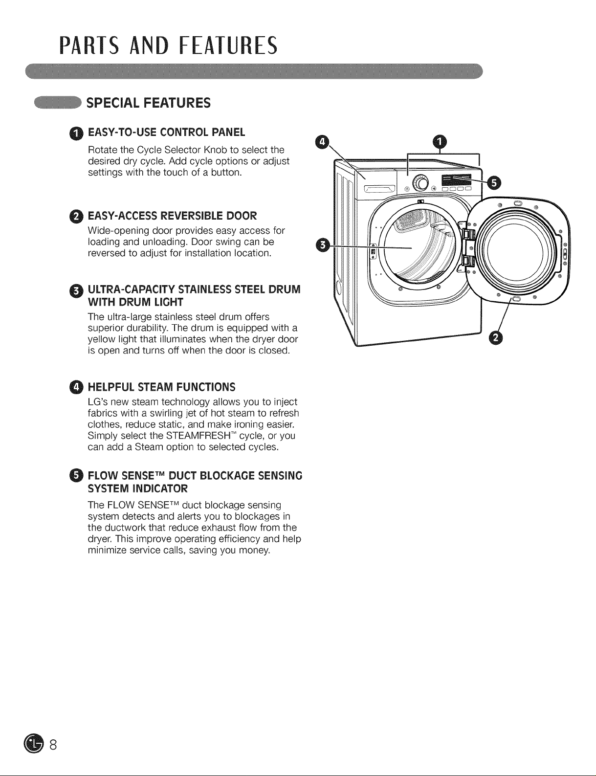
O EASY-TO-USE CONTROL PANEL
Rotate the Cycle Selector Knob to select the
desired dry cycle. Add cycle options or adjust
settings with the touch of a button.
EASY-ACCESS REVERSIBLE DOOR
Wide-opening door provides easy access for
loading and unloading. Door swing can be
reversed to adjust for installation location.
O ULTRA-CAPACITY STAINLESS STEEL DRUM
WITH DRUM LIGHT
The ultra-large stainless steel drum offers
superior durability. The drum is equipped with a
yellow light that illuminates when the dryer door
is open and turns off when the door is closed.
HELPFUL STEAM FUNCTIONS
O
LG's new steam technology allows you to inject
fabrics with a swirling jet of hot steam to refresh
clothes, reduce static, and make ironing easier.
Simply select the STEAMFRESH TMcycle, or you
can add a Steam option to selected cycles.
FLOW SENSE TM DUCT BLOCKAGE SENSING
SYSTEM INDICATOR
The FLOW SENSF mduct blockage sensing
system detects and alerts you to blockages in
the ductwork that reduce exhaust flow from the
dryer. This improve operating efficiency and help
minimize service calls, saving you money.
8
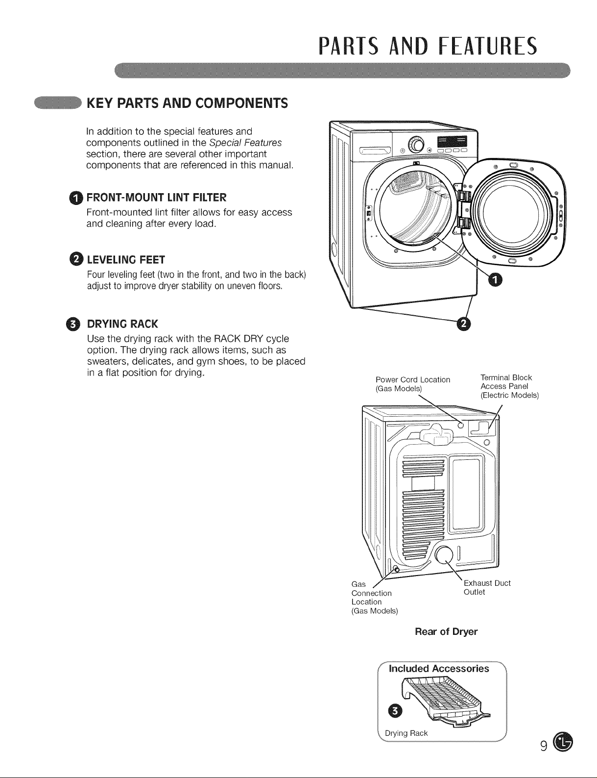
KEY PARTS AND COMPONENTS
In addition to the special features and
components outlined in the Special Features
section, there are several other important
components that are referenced in this manual.
FRONT-MOUNT LINT FILTER
O
Front-mounted lint filter allows for easy access
and cleaning after every load.
LEVELING FEET
Four leveling feet (two in the front, and two in the back)
adjust to improve dryer stability on uneven floors,
DRYING RACK
O
Use the drying rack with the RACK DRY cycle
option. The drying rack allows items, such as
sweaters, delicates, and gym shoes, to be placed
in a flat position for drying.
PARTSAND FEATU ES
Power Cord Location
(Gas Models)
Terminal Block
Access Panel
(Electric Models)
Gas
Connection
Location
(Gas Models)
Exhaust Duct
Outlet
Rear of Dryer
lncluded Accessories
J" 9
iNSTALLATiONiNSTRUCTIONS
iMPORTANT: Read all installation instructions completely before
installing and operating your dryer!
It is important that you review this entire manual before installing and using your dryer. Detailed instructions
concerning electrical connections, gas connections, and exhaust requirements are provided on the
following pages.
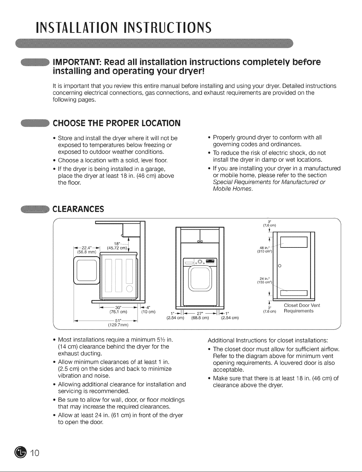
CHOOSE THE PROPER LOCATION
• Store and install the dryer where it will not be
exposed to temperatures below freezing or
exposed to outdoor weather conditions.
Choose a location with a solid, level floor.
If the dryer is being installed in a garage,
place the dryer at least 18 in. (46 cm) above
the floor.
CLEARANCES
S
18" ....
22.4"
(56.8 ram)
(45.72 cm)_
I_ 30"_ 1_'_4''
(76.1 cm) (10 cm)
51"_
(129.7mm)
1-_1I-,_ 27'-_1 I_1"
(2.54 cm) (68.6 cm) (2.54 cm)
Properly ground dryer to conform with all
governing codes and ordinances.
To reduce the risk of electric shock, do not
install the dryer in damp or wet locations.
If you are installing your dryer in a manufactured
or mobile home, please refer to the section
Special Requirements for Manufactured or
Mobile Homes.
3"
(7.6 cm)
48 in. 2 -
(310 cm 2)
24 ini 2
(155 cm 2)
J
Closet Door Vent
3"
(7.6 era) Requirements
10
• Most installations require a minimum 51/2in.
(14 cm) clearance behind the dryer for the
exhaust ducting.
Allow minimum clearances of at least 1 in.
(2.5 cm) on the sides and back to minimize
vibration and noise.
Allowing additional clearance for installation and
servicing is recommended.
Be sure to allow for wall, door, or floor moldings
that may increase the required clearances.
Allow at least 24 in. (61 cm) in front of the dryer
to open the door.
Additional instructions for closet installations:
The closet door must allow for sufficient airflow.
Refer to the diagram above for minimum vent
opening requirements. A Iouvered door is also
acceptable.
Make sure that there is at least 18 in. (46 cm) of
clearance above the dryer.
INSTALLATIONINSTRUCTIONS
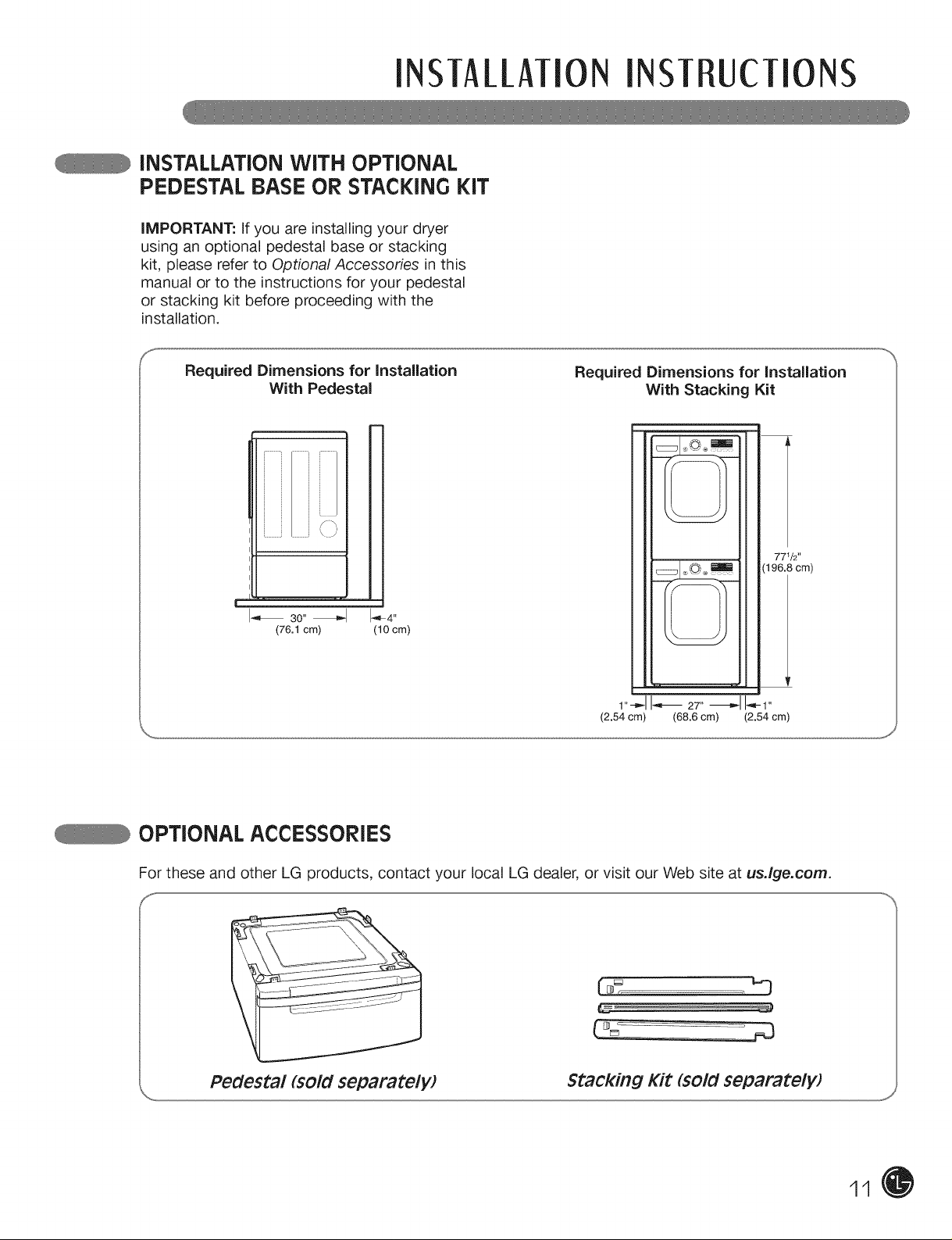
iNSTALLATiON WITH OPTIONAL
PEDESTAL BASE OR STACKING KIT
iMPORTANT: If you are installing your dryer
using an optional pedestal base or stacking
kit, please refer to Optional Accessories in this
manual or to the instructions for your pedestal
or stacking kit before proceeding with the
installation.
Required Dimensions for installation
With Pedestal
j y
\ )
I_ 30"_1 I-_4"
(76.1 cm) (10 cm)
Required Dimensions for installation
With Stacking Kit
77_I2''
(196.8 cm)
1"-_1I-,_ 27" _ _1-1"
(2.54 cm) (68.6 cm) (2.54 cm)
OPTIONAL ACCESSORIES
For these and other LG products, contact your local LG dealer, or visit our Web site at usJge.com.
Pedestal (sold separatelW Stacking Kit (sold separately)
11
INSTALLATIONINSTRUCTIONS
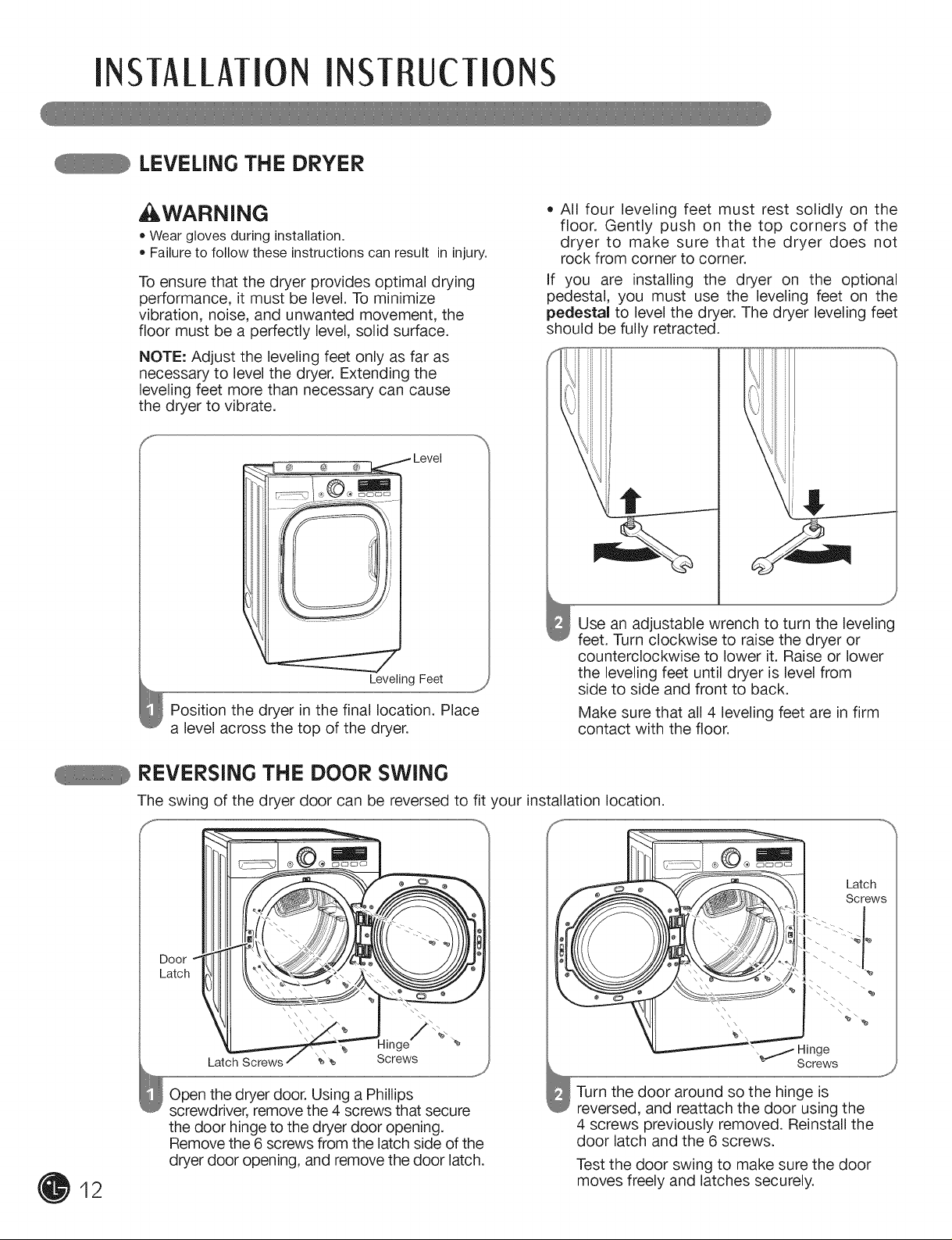
LEVELING THE DRYER
,WARNING
• Weargloves during installation.
• Failureto follow these instructions can result ininjury.
To ensure that the dryer provides optimal drying
performance, it must be level. To minimize
vibration, noise, and unwanted movement, the
floor must be a perfectly level, solid surface.
NOTE: Adjust the leveling feet only as far as
necessary to level the dryer. Extending the
leveling feet more than necessary can cause
the dryer to vibrate.
® c_ _ Level
Leveling Feet
Position the dryer in the final location. Place
a level across the top of the dryer.
j,
• All four leveling feet must rest solidly on the
floor. Gently push on the top corners of the
dryer to make sure that the dryer does not
rock from corner to corner.
If you are installing the dryer on the optional
pedestal, you must use the leveling feet on the
pedestal to level the dryer. The dryer leveling feet
should be fully retracted.
Use an adjustable wrench to turn the leveling
feet. Turn clockwise to raise the dryer or
counterclockwise to lower it. Raise or lower
the leveling feet until dryer is level from
side to side and front to back.
Make sure that all 4 leveling feet are in firm
contact with the floor.
12
REVERSING THE DOOR SWING
The swing of the dryer door can be reversed to fit your installation location.
/'%.
e
Latch Screws _ _
Open the dryer door. Using a Phillips
screwdriver, remove the 4 screws that secure
the door hinge to the dryer door opening.
Remove the 6 screws from the latch side of the
dryer door opening, and remove the door latch.
Screws
Turn the door around so the hinge is
reversed, and reattach the door using the
4 screws previously removed. Reinstall the
door latch and the 6 screws.
Test the door swing to make sure the door
moves freely and latches securely.
, _t Hinge
Screws
Latch
Screws
INSTALLATIONINSTRUCTIONS
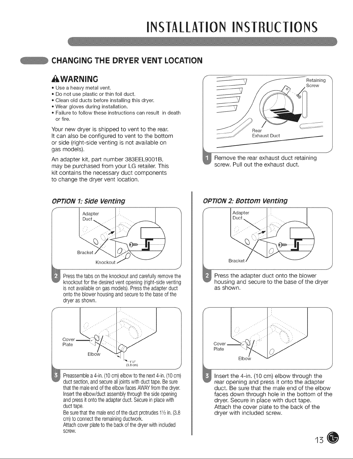
CHANGING THE DRYER VENT LOCATION
WARNING
• Usea heavy metal vent.
• Do not use plastic or thin foil duct.
• Cleanold ducts before installingthis dryer.
• Weargloves during installation.
• Failureto follow these instructions can result indeath
or fire.
Your new dryer is shipped to vent to the rear.
it can also be configured to vent to the bottom
or side (right-side venting is not available on
gas models).
An adapter kit, part number 383EEL9001B,
may be purchased from your LG retailer. This
kit contains the necessary duct components
to change the dryer vent location.
Retaining
Screw
Rear
Exhaust Duct
Remove the rear exhaust duct retaining
screw. Pull out the exhaust duct.
OPTION 2: BOttOm venting
/' I Adapter
Duct ,_
I
Bracket
Knockout
Pressthetabsonthe knockoutandcarefullyremovethe
knockoutforthedesiredventopening(right-sideventing
isnotavailableongas models).Presstheadapterduct
ontothe blowerhousingandsecureto thebaseofthe
dryerasshown.
Preassemblea4-in.(10cm)elbowtothenext4-in.(10cm)
ductsection,andsecurealljointswithducttape.Besure
thatthemaleendoftheelbowfacesAWAYfromthedryer.
Inserttheelbow/ductassemblythroughthesideopening
andpressitontotheadapterduct.Secureinplacewith
ducttape.
Besurethatthemaleendoftheductprotrudes11/2in.(3.8
cm)toconnecttheremainingductwork.
Attachcoverplatetothebackofthedryerwithincluded
screw.
Bracket
Press the adapter duct onto the blower
housing and secure to the base of the dryer
as shown.
Cover
Plate
J
insert the 4-in. (10 cm) elbow through the
rear opening and press it onto the adapter
duct. Be sure that the male end of the elbow
faces down through hole in the bottom of the
dryer. Secure in place with duct tape.
Attach the cover plate to the back of the
dryer with included screw.
15
INSTALLATIONINSTRUCTIONS
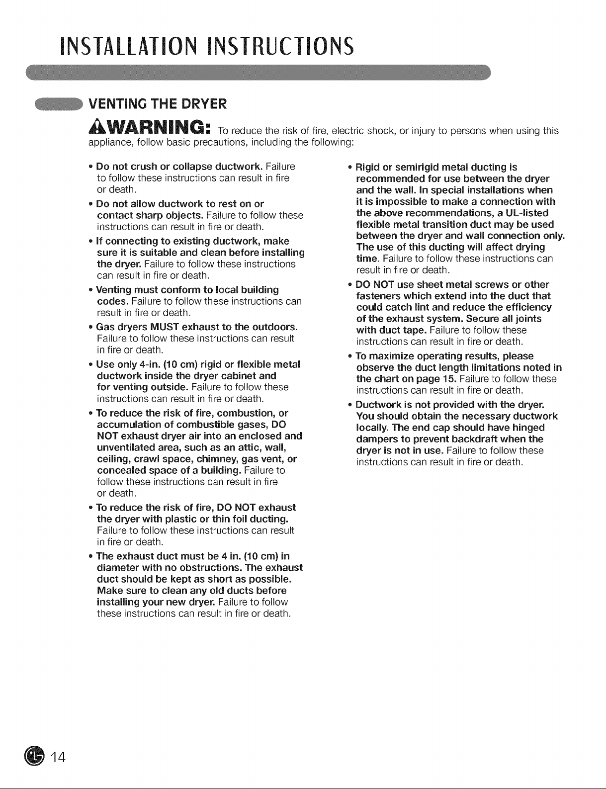
VENTING THE DRYER
WARN|NG: to reduce the risk of fire, electric shock, or injury to persons when using this
appliance, follow basic precautions, including the following:
, Do not crush or collapse ductwork. Failure
to follow these instructions can result in fire
or death.
• Do not allow ductwork to rest on or
contact sharp objects. Failure to follow these
instructions can result in fire or death.
• If connecting to existing ductwork, make
sure it is suitable and clean before installing
the dryer. Failure to follow these instructions
can result in fire or death.
• Venting must conform to local building
codes. Failure to follow these instructions can
result in fire or death.
Gas dryers MUST exhaust to the outdoors.
Failure to follow these instructions can result
in fire or death.
• Use only 4-in. {10 era} rigid or flexible metal
ductwork inside the dryer cabinet and
for venting outside. Failure to follow these
instructions can result in fire or death.
• To reduce the risk of fire, combustion, or
accumulation of combustible gases, DO
NOT exhaust dryer air into an enclosed and
unventilated area, such as an attic, wall,
ceiling, crawl space, chimney, gas vent, or
concealed space of a building. Failure to
follow these instructions can result in fire
or death.
• To reduce the risk of fire, DO NOT exhaust
the dryer with plastic or thin foil ducting.
Failure to follow these instructions can result
in fire or death.
• The exhaust duct must be 4 in. {10 cm) in
diameter with no obstructions. The exhaust
duct should be kept as short as possible.
Make sure to clean any old ducts before
installing your new dryer. Failure to follow
these instructions can result in fire or death.
, Rigid or semirigid metal ducting is
recommended for use between the dryer
and the wall. in special installations when
it is impossible to make a connection with
the above recommendations, a UL=listed
flexible metal transition duct may be used
between the dryer and wall connection only.
The use of this ducting will affect drying
time. Failure to follow these instructions can
result in fire or death.
DO NOT use sheet metal screws or other
fasteners which extend into the duct that
could catch lint and reduce the efficiency
of the exhaust system. Secure all joints
with duct tape. Failure to follow these
instructions can result in fire or death.
• To maximize operating results, please
observe the duct length limitations noted in
the chart on page 15. Failure to follow these
instructions can result in fire or death.
• Ductwork is not provided with the dryer.
You should obtain the necessary ductwork
locally. The end cap should have hinged
dampers to prevent backdraft when the
dryer is not in use. Failure to follow these
instructions can result in fire or death.
14
INSTALLATIONINSTRUCTIONS
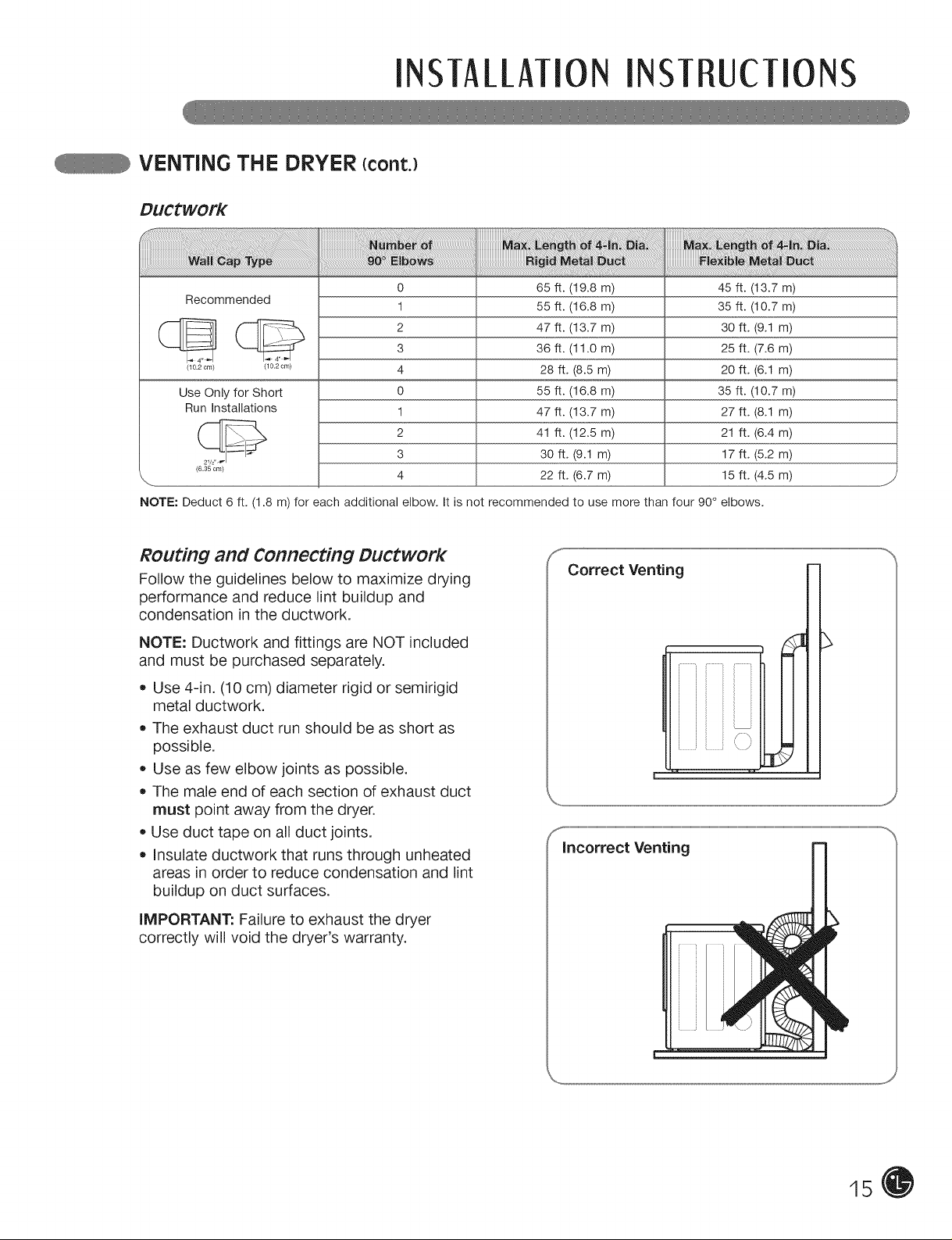
VENTING THE DRYER {cont.)
DuCtwork
Recommended
__ 2 47 ft. (13.7 m) 30 ft. (9.1 m)3 36 ft. (11.0 m) 25 ft. (7.6 m)
/_02om/ /_o_om/ 4 28 ft. (8.5 m) 20 ft. (6.1 m)
Use Only for Short 0 55 ft. (16.8 m) 35 ft. (10.7 m)
Run Installations 1 47 ft. (13.7 m) 27 ft. (8.1 m)
____ 2 41 ft. (12.5 m) 21 ft. (6.4 m)
,,,_ 4 22 ft. (6.7 m) 15 ft. (4.5 m) j
NOTE: Deduct 6 ft. (1.8 m) for each additional elbow. It is not recommended to use more than four 90° elbows.
(6.35 cm)
0 65 ft. (19.8 m) 45 ft. (13.7 m)
1 55 ft. (16.8 m) 35 ft. (10.7 m)
3 30 ft. (9.1 m) 17 ft. (5.2 m)
ROuting and Connecting Ductwork
Follow the guidelines below to maximize drying
performance and reduce lint buildup and
condensation in the ductwork.
NOTE: Ductwork and fittings are NOT included
and must be purchased separately.
• Use 4-in. (10 cm) diameter rigid or semirigid
metal ductwork.
The exhaust duct run should be as short as
possible.
Use as few elbow joints as possible.
The male end of each section of exhaust duct
must point away from the dryer.
Use duct tape on all duct joints.
Insulate ductwork that runs through unheated
areas in order to reduce condensation and lint
buildup on duct surfaces.
Correct Venting
Incorrect Venting
IMPORTANT: Failure to exhaust the dryer
correctly will void the dryer's warranty.
15
INSTALLATIONINSTRUCTIONS
cONNEcTiNG GASDRYERS
_WARN|NG-" To reduce the risk of fire, electric shock, or injury to persons when using this
appliance, follow basic precautions, including the following:
• Gas supply requirements:
As shipped from the factory, this dryer is
configured for use with natural gas. it can be
converted for use with LP (Liquefied Propane)
gas. Gas pressure must not exceed 13 in.
water column.
• A qualified service or gas company technician
must connect the dryer to the gas service.
Failure to do so can result in fire, explosion,
or death.
Isolate the dryer from the gas supply system
by closing its individual manual shutoff valve
during any pressure testing of the gas supply.
Failure to do so can result in fire, explosion,
or death.
• Supply line requirements:
Your laundry room must have a rigid gas
supply line to your dryer, in the United States,
an individual manual shutoff valve MUST be
installed within at least 6 ft. (1.8 m) of the dryer,
in accordance with the National Fuel Gas Code
ANSi Z223.1 or Canadian gas installation code
CSA B149.1. A 1/Sqn. NPT pipe plug must
be installed. Failure to do so can result in fire,
explosion, or death.
• If using a rigid pipe, the rigid pipe should be
1/2-in. IPS. If acceptable under local codes
and ordinances and when acceptable to your
gas supplier, 3/8-in. approved tubing may be
used where lengths are less than 20 ft. (6.1
m). Larger tubing should be used for lengths
in excess of 20 ft. (6.1 m). Failure to do so can
result in fire, explosion, or death.
Connect the dryer to the type of gas shown on
the nameplate. Failure to do so can result in fire,
explosion, or death.
* To prevent contamination of the gas valve,
purge the gas supply of air and sediment
before connecting the gas supply to the dryer.
Before tightening the connection between the
gas supply and the dryer, purge remaining air
until the odor of gas is detected. Failure to do
so can result in fire, explosion, or death.
* DO NOT use an open flame to inspect for gas
leaks. Use a noncorrosive leak-detection fluid.
Failure to do so can result in fire, explosion, or
death.
* Use only a new AGA- or CSA-certified gas
supply line with flexible stainless steel
connectors. Failure to do so can result in fire,
explosion, or death.
* Securely tighten all gas connections. Failure
to do so can result in fire, explosion, or death.
* Use Teflon ®tape or a pipe-joint compound that
is insoluble in Liquefied Petroleum (LP) gas on
all pipe threads. Failure to do so can result in fire,
explosion, or death.
* DO NOT attempt any disassembly of the dryer;
any disassembly requires the attention and
tools of an authorized and qualified service
person or company. Failure to do so can result
in fire, explosion, or death.
16
Electrical Requirements for Gas MOdelS Only
_WARN|NG-" TOreduce the risk of fire, electric shock, or injury to persons when using this
appliance, follow basic precautions, including the following:
• Do not, under any circumstances, cut or
remove the third (ground) prong from the power
cord. Failure to follow this warning can result in
fire, explosion, or death.
For personal safety, this dryer must be properly
grounded. Failure to follow this warning can result
in fire, explosion, or death.
The power cord of this dryer is equipped with
a 3-prong (grounding) plug which mates with
a standard 3-prong (grounding) wall outlet
to minimize the possibility of electric shock
hazard from this appliance. Failure to follow this
warning can result in fire, explosion, or death.
* This dryer must be plugged into a
120-VAC, 60-Hz. grounded outlet protected by
a 15-ampere fuse or circuit breaker. Failure to
follow this warning can result in fire, explosion,
or death.
* Where a standard 2-prong wall outlet is
encountered, it is your personal responsibility
and obligation to have it replaced with a
properly grounded 3-prong wall outlet. Failure
to follow this warning can result in fire, explosion,
or death.
INSTAllATIONINSTRUCTIONS
cONNEcTiNG GAS DRYERS (cont.)
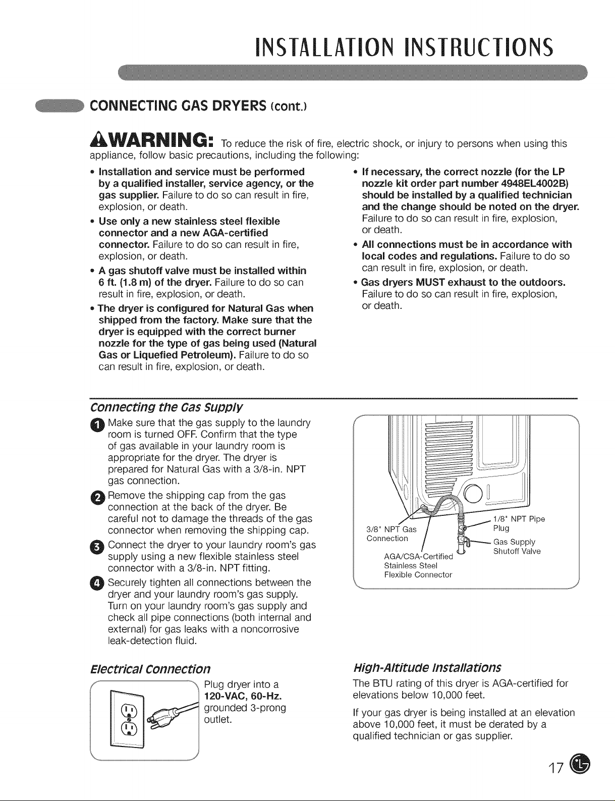
WARNING:
appliance, follow basic precautions, including the following:
• installation and service must be performed
by a qualified installer, service agency, or the
gas supplier. Failure to do so can result in fire,
explosion, or death.
• Use only a new stainless steel flexible
connector and a new AGA=certified
connector. Failure to do so can result in fire,
explosion, or death.
• A gas shutoff valve must be installed within
6 ft. (1.8 m) of the dryer. Failure to do so can ,
result in fire, explosion, or death.
• The dryer is configured for Natural Gas when
shipped from the factory. Make sure that the
dryer is equipped with the correct burner
nozzle for the type of gas being used (Natural
Gas or Liquefied Petroleum). Failure to do so
can result in fire, explosion, or death.
To reduce the risk of fire, electric shock, or injury to persons when using this
Connecting the Gas Supply
O Make sure that the gas supply to the laundry
room is turned OFR Confirm that the type
of gas available in your laundry room is
appropriate for the dryer. The dryer is
prepared for Natural Gas with a 3/8-in. NPT
gas connection.
0) Remove the shipping cap from the gas
connection at the back of the dryer. Be
careful not to damage the threads of the gas
connector when removing the shipping cap.
Connect the dryer to your laundry room's gas
supply using a new flexible stainless steel
connector with a 3/8-in. NPT fitting.
_ Securely all connections between the
dryer and your laundry room's gas supply.
Turn on your laundry room's gas supply and
check all pipe connections (both internal and
external) for gas leaks with a noncorrosive
leak-detection fluid.
tighten
If necessary, the correct nozzle {for the LP
nozzle kit order part number 4948EL4002B)
should be installed by a qualified technician
and the change should be noted on the dryer.
Failure to do so can result in fire, explosion,
or death.
All connections must be in accordance with
local codes and regulations. Failure to do so
can result in fire, explosion, or death.
Gas dryers MUST exhaust to the outdoors.
Failure to do so can result in fire, explosion,
or death.
3/8" NPT Gas Plug
Connection Supply
AGA/CSA-Certified
Stainless Steel
Flexible Connector
NPT Pipe
Shutoff Valve
Electrical Connection
Plug dryer into a
120=VAC, 60-Hz.
grounded 3-prong
outlet.
High-Altitude Installations
The BTU rating of this dryer is AGA-certified for
elevations below 10,000 feet.
if your gas dryer is being installed at an elevation
above 10,000 feet, it must be derated by a
qualified technician or gas supplier.
17
INSTALLATIONINST UCTIONS
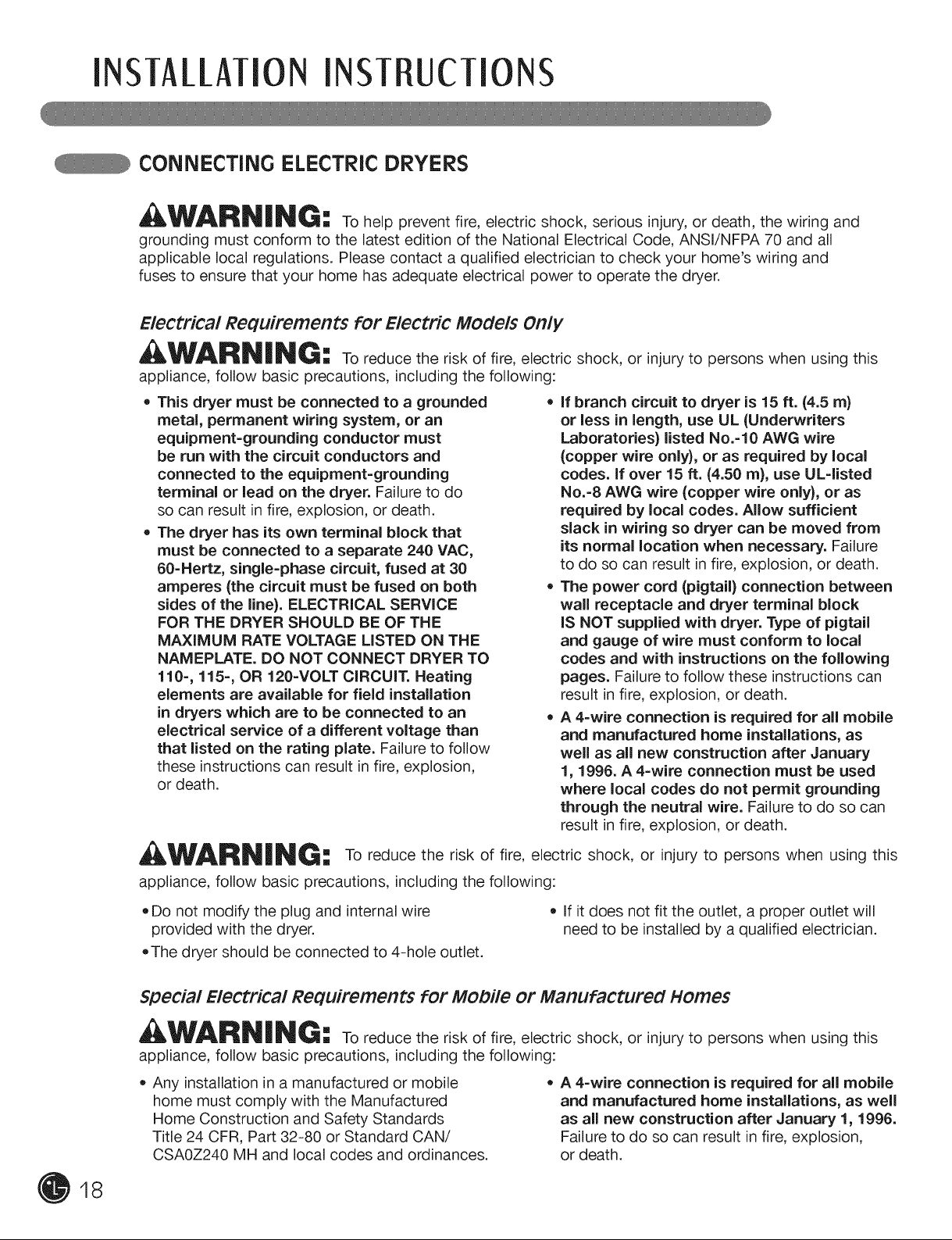
cONNEcTiNG ELEcTRic DRYERS
_WARN|NG -= To help prevent fire, electric shock, serious injury, or death, the wiring and
grounding must conform to the latest edition of the National Electrical Code, ANSI/NFPA 70 and all
applicable local regulations. Please contact a qualified electrician to check your home's wiring and
fuses to ensure that your home has adequate electrical power to operate the dryer.
Electrical Requirements for Electric MOdelS Only
WARNIN¢: To reduce the risk of fire, electric shock, or injury to persons when using this
appliance, follow basic precautions, including the following:
• This dryer must be connected to a grounded
metal, permanent wiring system, or an
equipment=grounding conductor must
be run with the circuit conductors and
connected to the equipment=grounding
terminal or lead on the dryer. Failure to do
so can result in fire, explosion, or death.
• The dryer has its own terminal block that
must be connected to a separate 240 VAC,
60=Hertz, single=phase circuit, fused at 30
amperes (the circuit must be fused on both
sides of the line). ELECTRICAL SERVICE
FOR THE DRYER SHOULD BE OF THE
MAXIMUM RATE VOLTAGE LISTED ON THE
NAMEPLATE. DO NOT CONNECT DRYER TO
110=, 115=, OR 120=VOLT CIRCUIT. Heating
elements are available for field installation
in dryers which are to be connected to an
electrical service of a different voltage than
that listed on the rating plate. Failure to follow
these instructions can result in fire, explosion,
or death.
if branch circuit to dryer is 15 ft. (4.5 m)
or less in length, use UL (Underwriters
Laboratories) listed No.=10 AWG wire
(copper wire only), or as required by local
codes. If over 15 ft. (4.50 m), use UL=listed
No.=8 AWG wire (copper wire only), or as
required by local codes. Allow sufficient
slack in wiring so dryer can be moved from
its normal location when necessary. Failure
to do so can result in fire, explosion, or death.
The power cord (pigtail) connection between
wall receptacle and dryer terminal block
IS NOT supplied with dryer. Type of pigtail
and gauge of wire must conform to local
codes and with instructions on the following
pages. Failure to follow these instructions can
result in fire, explosion, or death.
A 4=wire connection is required for aii mobile
and manufactured home installations, as
well as all new construction after January
1, 1996. A 4-wire connection must be used
where local codes do not permit grounding
through the neutral wire. Failure to do so can
result in fire, explosion, or death.
18
_W_ILR_II_|NG= = To reduce the risk of fire, electric shock, or injury to persons when using this
appliance, follow basic precautions, including the following:
• Do not modify the plug and internal wire
provided with the dryer.
,The dryer should be connected to 4-hole outlet.
• if it does not fit the outlet, a proper outlet will
need to be installed by a qualified electrician.
Special Electrical Requirements for Mobile or Manufactured Homes
_II_W_ILR_II!_ | _II_G =--To reduce the risk of fire, electric shock, or injury to persons when using this
appliance, follow basic precautions, including the following:
• Any installation in a manufactured or mobile
home must comply with the Manufactured
Home Construction and Safety Standards
Title 24 CFR, Part 32-80 or Standard CAN/
CSAOZ240 MH and local codes and ordinances.
• A 4-wire connection is required for all mobile
and manufactured home installations, as well
as all new construction after January 1, 1996.
Failure to do so can result in fire, explosion,
or death.
INSTAllATIONINST UCTIONS
cONNEcTiNG ELEcTRic DRYERS {cont.)
USA ONLY
WARN|NG:
= Connect the power cord to the terminal block. Each colored wire should be connected
to same color screw. Wire color indicated on manual is connected to the same color
screw in block. Failure to follow these instructions may result in a short or overload.
= Grounding through the neutral conductor is prohibited for: (1) new branch-circuit
installations, (2) mobile homes, (3) recreational vehicles, and (4) areas where local
codes prohibit grounding through the neutral conductor.
©
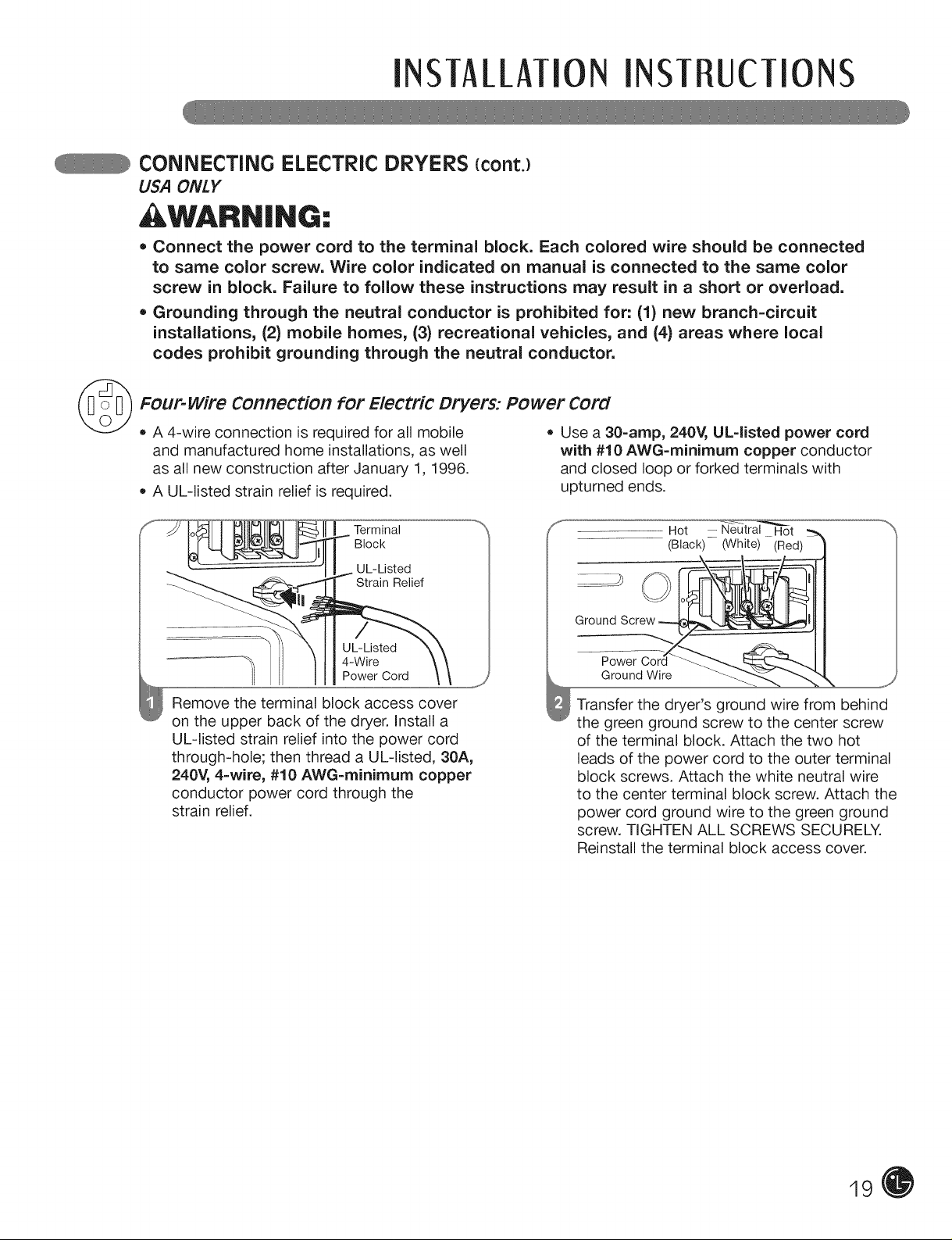
Four-wire Connection for Electric Dryers: Power Cord
• A 4-wire connection is required for all mobile
and manufactured home installations, as well
as all new construction after January 1, 1996.
A UL-listed strain relief is required.
Terminal
Block
UL-Listed
Relief
UL-Listed
4-Wire
Power Cord
Remove the terminal block access cover
on the upper back of the dryer. Install a
UL-listed strain relief into the power cord
through-hole; then thread a UL-listed, 30A,
240V, 4-wire, #10 AWG=minirnurn copper
conductor power cord through the
strain relief.
Use a 30=amp, 240V, UL=listed power cord
with #10 AWG=minimum copper conductor
and closed loop or forked terminals with
upturned ends.
...............................(Black) (White) (Red)
Ground Screw ---tiG_t._l
Transfer the dryer's ground wire from behind
the green ground screw to the center screw
of the terminal block. Attach the two hot
leads of the power cord to the outer terminal
block screws. Attach the white neutral wire
to the center terminal block screw. Attach the
power cord ground wire to the green ground
screw. TIGHTEN ALL SCREWS SECURELY.
Reinstall the terminal block access cover.
Hot ........Neutral Hot
GroundWire ...._
19
INSTALLATIONINST UCTIONS
cONNEcTiNG ELEcTRic DRYERS {cont.)
USA ONLY
, WARN|NG:
• Connect the power cord to the terminal block. Each colored wire should be connected
to same color screw. Wire color indicated on manual is connected to the same color
screw in block. Failure to follow these instructions may result in a short or overload.
• Grounding through the neutral conductor is prohibited for: (1) new branch-circuit
installations, (2) mobile homes, (3) recreational vehicles, and (4) areas where local
codes prohibit grounding through the neutral conductor.
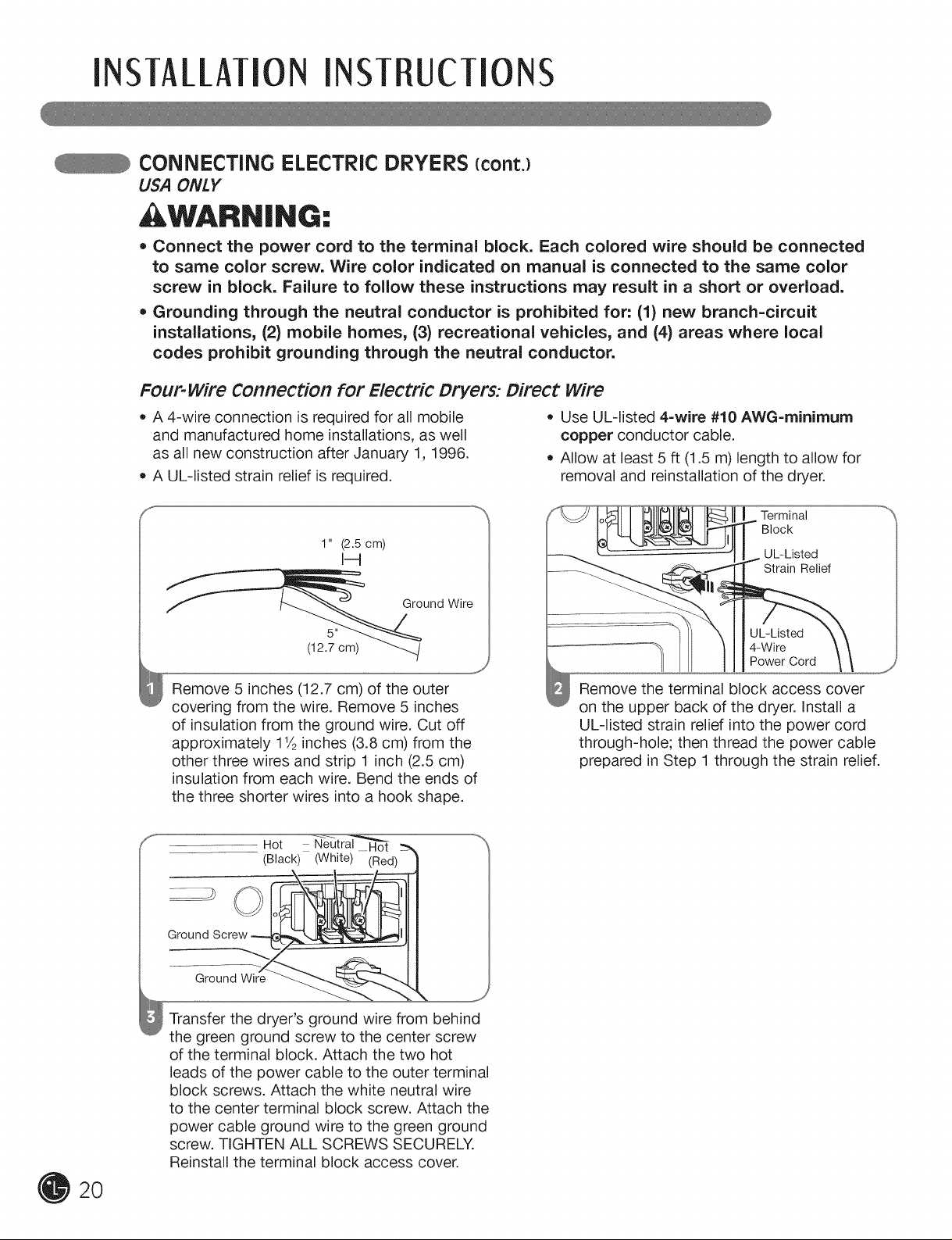
Four-wire Connection for Electric Dryers: Direct wire
• A 4-wire connection is required for all mobile
and manufactured home installations, as well
as all new construction after January 1, 1996.
A UL-listed strain relief is required.
Use UL-listed 4-wire #10 AWG=minirnum
copper conductor cable.
Allow at least 5 ft (1.5 m) length to allow for
removal and reinstallation of the dryer.
S
1" (2.5 cm)
I-4
f und Wire
ii
(12.7 cm)
Remove 5 inches (12.7 cm) of the outer
covering from the wire. Remove 5 inches
of insulation from the ground wire. Cut off
approximately 11/2inches (3.8 cm) from the
other three wires and strip 1 inch (2.5 cm)
insulation from each wire. Bend the ends of
the three shorter wires into a hook shape.
Hot N_ -_n
(Black) (White) (Red)
Ground Screw
Terminal
Block
UL-Listed
Strain Relief
UL-Listed
Power Cord
4-Wire
Remove the terminal block access cover
on the upper back of the dryer. Install a
UL-listed strain relief into the power cord
through-hole; then thread the power cable
prepared in Step 1 through the strain relief.
2O
Ground Wire __
Transfer the dryer's ground wire from behind
the green ground screw to the center screw
of the terminal block. Attach the two hot
leads of the power cable to the outer terminal
block screws. Attach the white neutral wire
to the center terminal block screw. Attach the
power cable ground wire to the green ground
screw. TIGHTEN ALL SCREWS SECURELY.
Reinstall the terminal block access cover.
INSTAllATION INST UCTIONS
cONNEcTiNG ELEcTRic DRYERS {cont.)
USA ONLY
WARN|NG:
• Connect the power cord to the terminal block. Each colored wire should be connected
to same color screw. Wire color indicated on manual is connected to the same color
screw in block. Failure to follow these instructions may result in a short or overload.
• Grounding through the neutral conductor is prohibited for: (1) new branch-circuit
installations, (2) mobile homes, (3) recreational vehicles, and (4) areas where local
codes prohibit grounding through the neutral conductor.
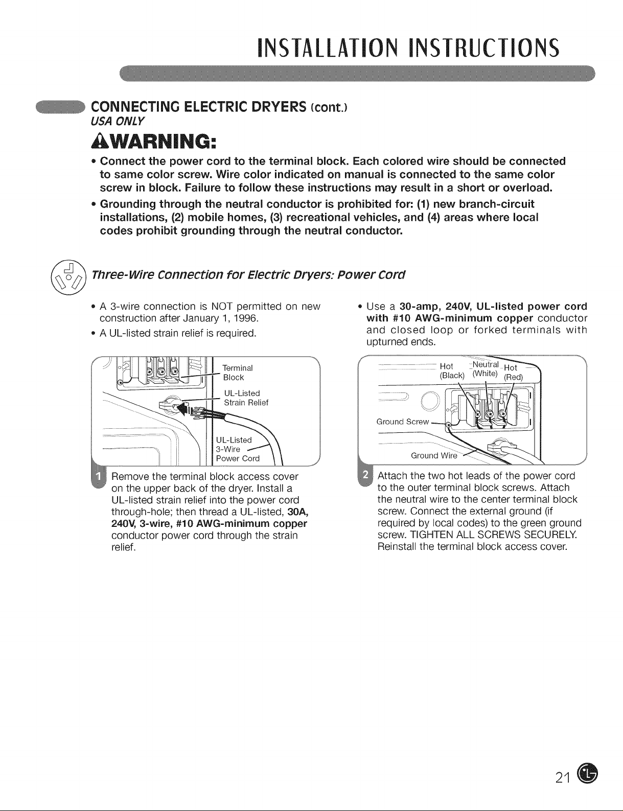
Three-wire Connection for Electric Dryers: Power Cord
• A 3-wire connection is NOT permitted on new
construction after January 1, 1996.
A UL-listed strain relief is required.
Terminal
Block
UL-Listed
Strain Relief
3-Wire
Power Cord
Remove the terminal block access cover
on the upper back of the dryer. Install a
UL-listed strain relief into the power cord
through-hole; then thread a UL-listed, 30A,
240V, 3=wire, #10 AWG=minirnurn copper
conductor power cord through the strain
relief.
J
= Use a 30=amp, 240V, UL=listed power cord
with #10 AWG=rninirnum copper conductor
and closed loop or forked terminals with
upturned ends.
..... Hot
Attach the two hot leads of the power cord
to the outer terminal block screws. Attach
the neutral wire to the center terminal block
screw. Connect the external ground (if
required by local codes) to the green ground
screw. TIGHTEN ALL SCREWS SECURELY.
Reinstall the terminal block access cover.
21
INSTAllATIONINST UCTIONS
cONNEcTiNG ELEcTRic DRYERS {cont.)
USA ONLY
WARN|NG:
= Connect the power cord to the terminal block. Each colored wire should be connected
to same color screw. Wire color indicated on manual is connected to the same color
screw in block. Failure to follow these instructions may result in a short or overload.
= Grounding through the neutral conductor is prohibited for: (1) new branch-circuit
installations, (2) mobile homes, (3) recreational vehicles, and (4) areas where local
codes prohibit grounding through the neutral conductor.
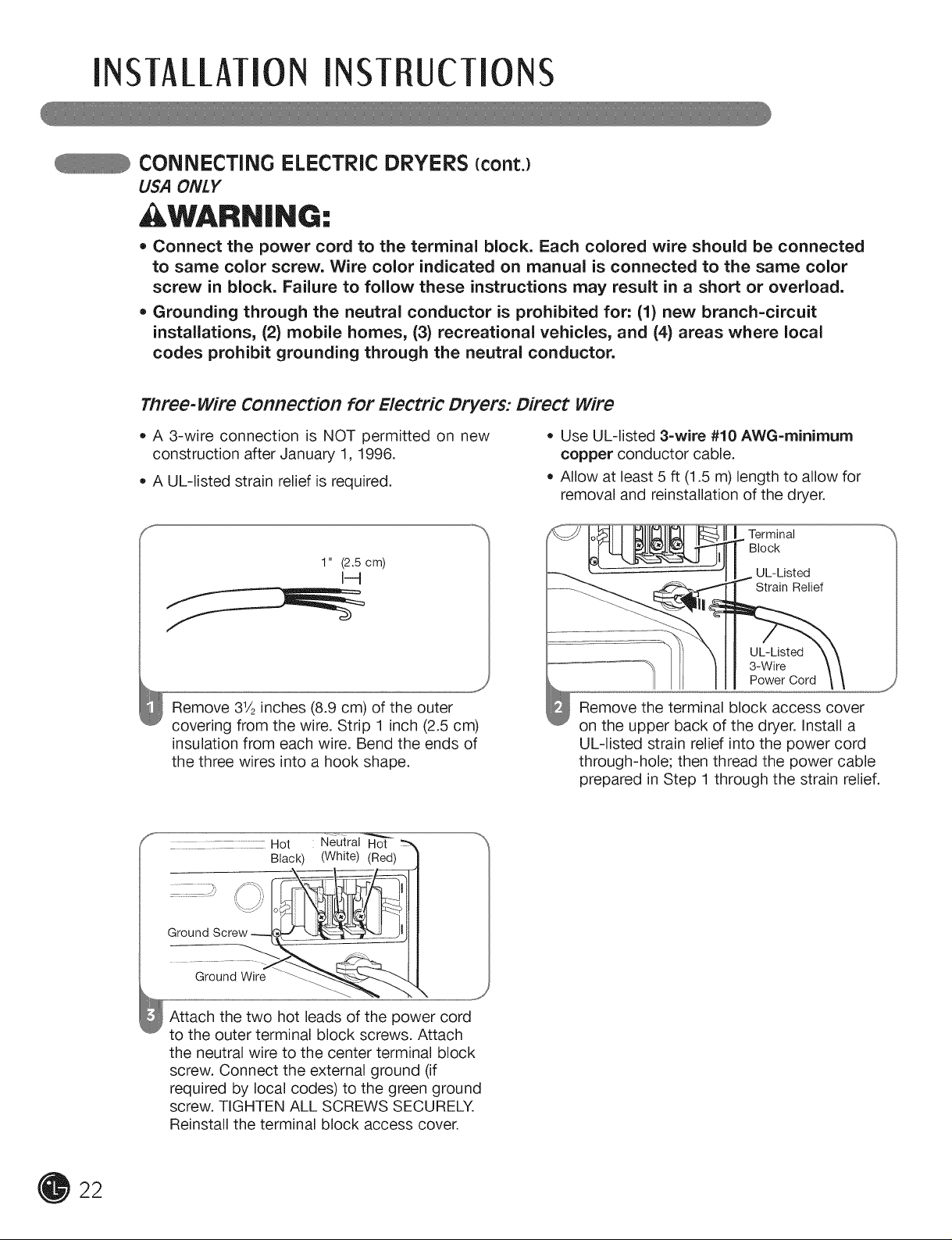
Three-wire Connection for Electric Dryers: Direct wire
• A 3-wire connection is NOT permitted on new • Use UL-listed 3=wire #10 AWG=minirnurn
construction after January 1, 1996. copper conductor cable.
• A UL-listed strain relief is required. • Allow at least 5 ft (1.5 m) length to allow for
removal and reinstallation of the dryer.
S
1" (2.5 cm)
Remove 31/2inches (8.9 cm) of the outer
covering from the wire. Strip 1 inch (2.5 cm)
insulation from each wire. Bend the ends of
the three wires into a hook shape.
.............. : Hot Neutral Hot
Black) (White) (Red)
Ground
Ground Wire
Terminal
Block
UL-Listed
Strain Relief
UL-Listed
3-Wire
Power Cord
Remove the terminal block access cover
on the upper back of the dryer. Install a
UL-listed strain relief into the power cord
through-hole; then thread the power cable
prepared in Step 1 through the strain relief.
22
Attach the two hot leads of the power cord
to the outer terminal block screws. Attach
the neutral wire to the center terminal block
screw. Connect the external ground (if
required by local codes) to the green ground
screw. TIGHTEN ALL SCREWS SECURELY.
Reinstall the terminal block access cover.
INSTAllATION INST UCTIONS
SPEciAL REQUIREMENTS FOR MANUFACTURED OR MOBILE HOMES
Any installation in a manufactured or mobile
home must comply with the Manufactured Home
Construction and Safety Standards Title 24 CFR,
Part 32-80 or Standard CAN/CSAOZ240 MH and
local codes and ordinances. If you are uncertain
whether your proposed installation will comply
with these standards, please contact a service
and installation professional for assistance.
• A gas dryer must be permanently attached to
the floor.
The electrical connection for an electric dryer
must be a 4-wire connection. More detailed
information concerning the electrical connection
is provided in the section Connecting Electric
Dryers.
To reduce the risk of combustion and fire, the
dryer must be vented to the outside.
DO NOT vent the dryer under a manufactured
home or mobile home.
Electric dryers may be vented to the outside
using the back, left, right, or bottom panel.
• Gas dryers may be vented to the outside using
the back, left, or bottom panel. Gas dryers may
not be vented to the outside using the right side
panel because of the burner housing.
The dryer exhaust duct must be affixed securely
to the manufactured or mobile home structure,
and the exhaust duct must be made of a
material that will resist fire and combustion.
It is recommended that you use a rigid or
flexible metal duct.
DO NOT connect the dryer exhaust duct
to any other duct, vent, chimney, or other
exhaust duct.
Make sure the dryer has adequate access to
outside fresh air to ensure proper operation.
The opening for outside fresh air must be at
least 25 in2(163 cm2).
It is important that the clearance of the duct
from any combustible construction be at least
2 in. (5 cm), and when venting the dryer to
the outdoors, the dryer can be installed with a
clearance of 1 in. (2.5 cm) at the sides and back
of the dryer.
Please be aware that venting materials are
not supplied with the dryer. You should obtain
the venting materials necessary for proper
installation.
FINAL INSTALLATION CHECK
Once you have completed the installation of the dryer and it is in its final location, confirm proper operation
with the following tests and Duct Condition Testing on the following page.
Testing Dryer Heating
GAS MODELS
Close the dryer door, press the ON/OFF switch
to turn the dryer on, and start the dryer on a heat
setting. When the dryer starts, the igniter should
ignite the main burner.
NOTE: If all air is not purged from the gas line,
the gas igniter may turn off before the main
burner ignites. If this happens, the igniter will
reattempt gas ignition after approximately
two minutes.
ELECTRIC MODELS
Close the dryer door, press the ON/OFF switch
to turn the dryer on, and start the dryer on a heat
setting. The exhaust air should be warm after the
dryer has been operating for 3 minutes.
Checking Airflow
Effective dryer operation requires proper airflow.
The adequacy of the airflow can be measured
by evaluating the static pressure. Static pressure
in the exhaust duct can be measured with
a manometer, placed on the exhaust duct
approximately 2 ft. (60.9 cm) from the dryer.
Static pressure in the exhaust duct should not
exceed 0.6 in. (1.5 cm). The dryer should be
checked while the dryer is running with no load.
Checking Levelness
Once the dryer is in its final location, recheck
the dryer to be sure it is level. Make sure it is
level front to back and side to side, and that
all 4 leveling feet are firmly on the floor.
25
INSTALLATIONINSTRUCTIONS
FLOW CHECK (DUCT CONDiTiON TEST)
Your dryer features FlowSense TM, an innovative
sensing system that automatically detects blockages
and restrictions in dryer ductwork. Keeping ductwork
clean of lint buildup and free of restrictions allows
clothes to dry faster and reduces energy use.
NOTE: When the dryer is first installed, this test
should be performed to alert you to any existing
problems with the exhaust duct in your home.
However, since the test performed during normal
operation provides more accurate information on
the condition of the exhaust duct than does the
installation test, the number of bars displayed during
the two tests may not be the same.
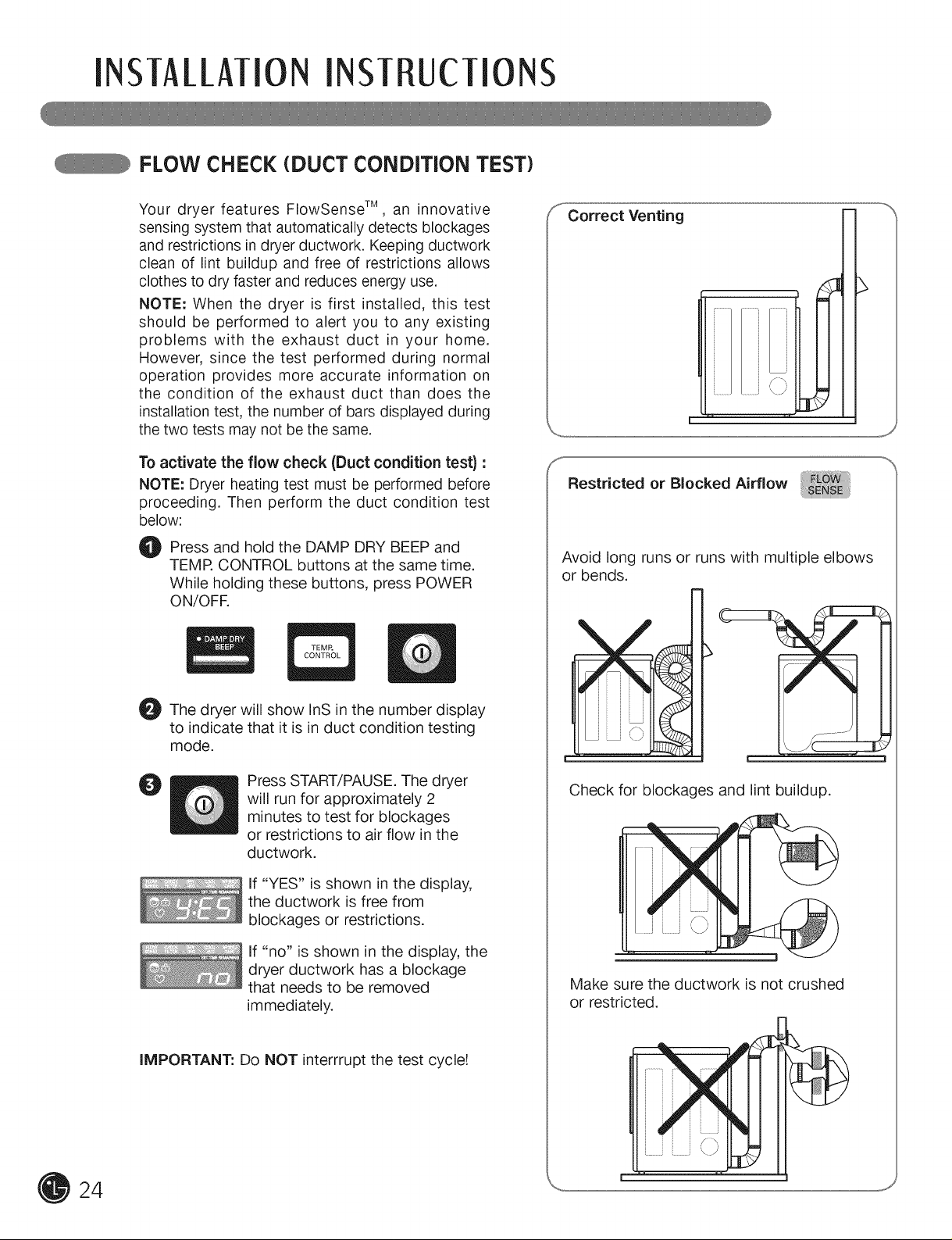
To activate the flow check (Duct condition test) :
NOTE: Dryer heating test must be performed before
proceeding. Then perform the duct condition test
below:
O Press and hold the DAMP DRY BEEP and
TEMR CONTROL buttons at the same time.
While holding these buttons, press POWER
ON/OFR
Correct Venting
J
Restricted or Blocked Airflow
Avoid long runs or runs with multiple elbows
or bends.
O The dryer will show InS in the number display
to indicate that it is in duct condition testing
mode.
O
iMPORTANT: Do NOT interrrupt the test cycle!
Press START/PAUSE. The dryer
will run for approximately 2
minutes to test for blockages
or restrictions to air flow in the
ductwork.
If "YES" is shown in the display,
the ductwork is free from
blockages or restrictions.
If "no" is shown in the display, the
dryer ductwork has a blockage
that needs to be removed
immediately.
Check for blockages and lint buildup.
Make sure the ductwork is not crushed
or restricted.
HO TO USE
Following are instructions for starting and using your new dryer. Please refer to specific sections of this
manual for more detailed information. Important Warning: To reduce the risk of fire, electric shock,
or injury to persons, read this entire manual, including the Important Safety Instructions, before
operating this dryer.
SORTING LOADS
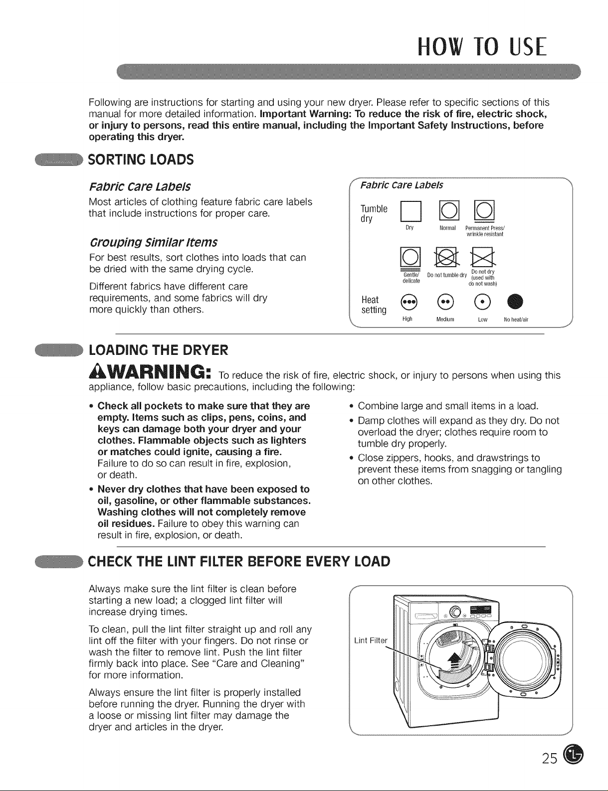
FaDri¢ Care Labels
Most articles of clothing feature fabric care labels
that include instructions for proper care.
....Fabric Care Labels
dry
Dry Normal PermanentPress/
wrinkle resistant
Grouping Similar Items
For best results, sort clothes into loads that can
be dried with the same drying cycle.
Different fabrics have different care
requirements, and some fabrics will dry
more quickly than others.
Gentle/ Do not tumble dry (used with
delicate donot wash)
Heat (_ (_ Q O
setting
High Medium Low Noheat!air
Donot dry
LOADING THE DRYER
WARNING: to reduce the risk of fire, electric shock, or injury to persons when using this
appliance, follow basic precautions, including the following:
• Check all pockets to make sure that they are
empty, items such as clips, pens, coins, and
keys can damage both your dryer and your
clothes. Flammable objects such as lighters
or matches could ignite, causing a fire.
Failure to do so can result in fire, explosion,
or death.
• Never dry clothes that have been exposed to
oil, gasoline, or other flammable substances.
Washing clothes will not completely remove
oil residues. Failure to obey this warning can
result in fire, explosion, or death.
• Combine large and small items in a load.
Damp clothes will expand as they dry. Do not
overload the dryer; clothes require room to
tumble dry properly.
Close zippers, hooks, and drawstrings to
prevent these items from snagging or tangling
on other clothes.
CHECK THE LINT FILTER BEFORE EVERY LOAD
Always make sure the lint filter is clean before
starting a new load; a clogged lint filter will
increase drying times.
To clean, pull the lint filter straight up and roll any
lint off the filter with your fingers. Do not rinse or
wash the filter to remove lint. Push the lint filter
firmly back into place. See "Care and Cleaning"
for more information.
Always ensure the lint filter is properly installed
before running the dryer. Running the dryer with
a loose or missing lint filter may damage the
dryer and articles in the dryer.
Lint Filter
25
OWTO USE
CONTROL PANEL FEATURES
Following are instructions for starting and using your new dryer. Please refer to specific sections
of this manual for more detailed information, important warning: To reduce the risk of fire,
electric shock, or injury to persons, read this entire manual, including the important safety
instructions, before operating this dryer.
e
0
26
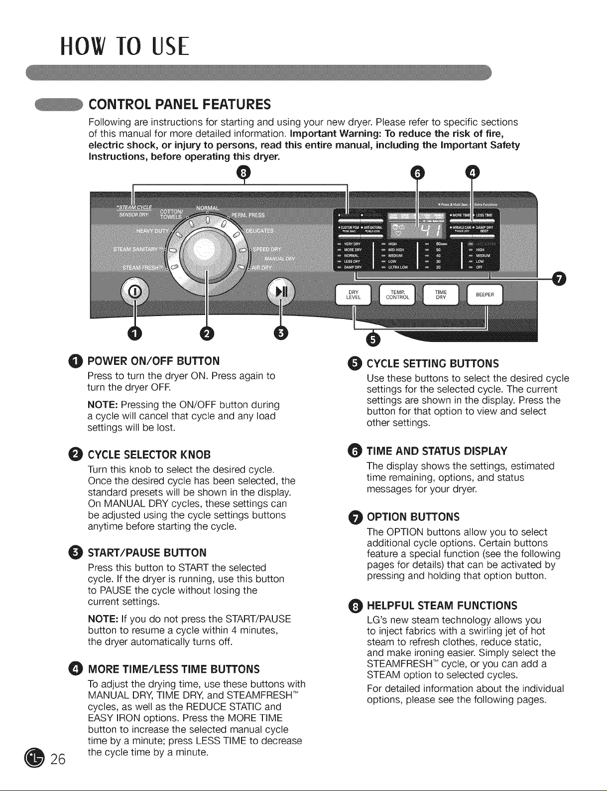
POWER ON/OFF BUTTON
Press to turn the dryer ON. Press again to
turn the dryer OFF.
NOTE: Pressing the ON/OFF button during
a cycle will cancel that cycle and any load
settings will be lost.
CYCLE SELECTOR KNOB
O
Turn this knob to select the desired cycle.
Once the desired cycle has been selected, the
standard presets will be shown in the display.
On MANUAL DRY cycles, these settings can
be adjusted using the cycle settings buttons
anytime before starting the cycle.
START/PAUSE BUTTON
O
Press this button to START the selected
cycle. If the dryer is running, use this button
to PAUSE the cycle without losing the
current settings.
NOTE: If you do not press the START/PAUSE
button to resume a cycle within 4 minutes,
the dryer automatically turns off.
MORE TIME/LESS TIME BUTTONS
O
To adjust the drying time, use these buttons with
MANUAL DRY, TIME DRY, and STEAMFRESH TM
cycles, as well as the REDUCE STATIC and
EASY IRON options. Press the MORE TIME
button to increase the selected manual cycle
time by a minute; press LESS TIME to decrease
the cycle time by a minute.
CYCLE SETTING BUTTONS
O
Use these buttons to select the desired cycle
settings for the selected cycle. The current
settings are shown in the display. Press the
button for that option to view and select
other settings.
TIME AND STATUS DISPLAY
O
The display shows the settings, estimated
time remaining, options, and status
messages for your dryer.
OPTION BUTTONS
O
The OPTION buttons allow you to select
additional cycle options. Certain buttons
feature a special function (see the following
pages for details) that can be activated by
pressing and holding that option button.
HELPFUL STEAM FUNCTIONS
O
LG's new steam technology allows you
to inject fabrics with a swirling jet of hot
steam to refresh clothes, reduce static,
and make ironing easier. Simply select the
STEAMFRESH TMcycle, or you can add a
STEAM option to selected cycles.
For detailed information about the individual
options, please see the following pages.
HO TO USE
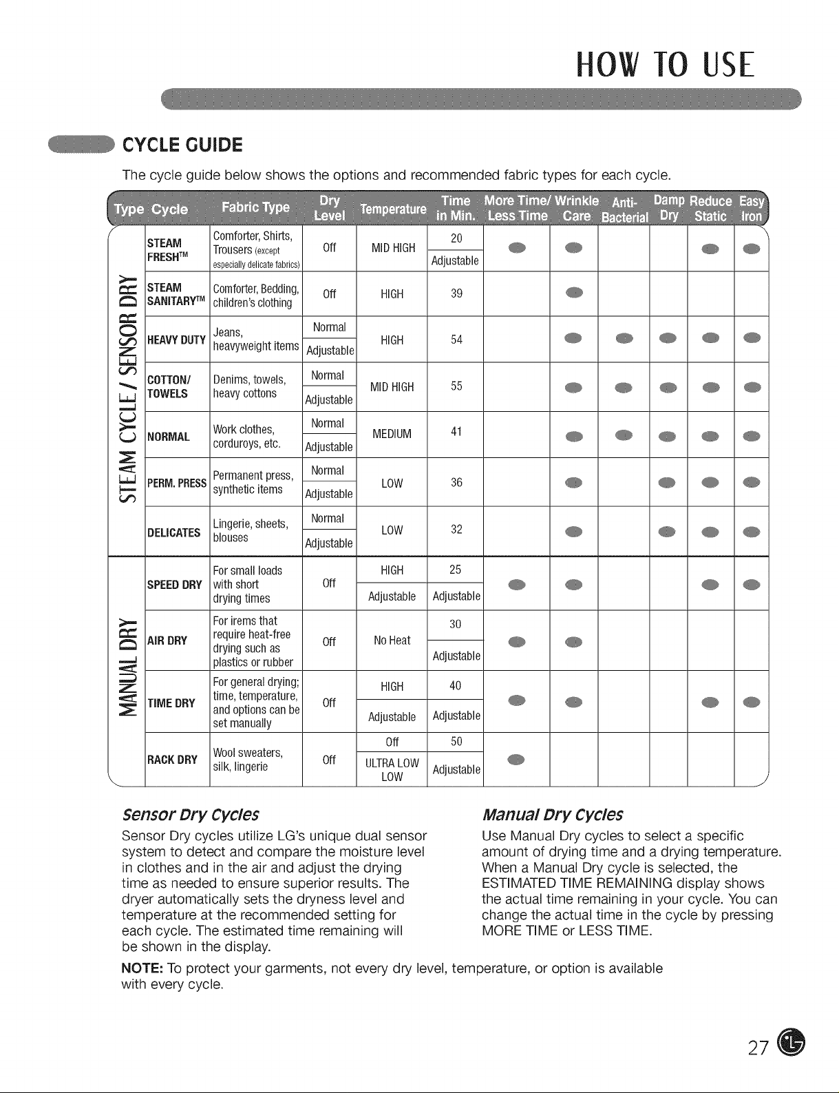
CYCLE GUIDE
The cycle guide below shows the options and recommended fabric types for each cycle.
STEAM comforter,shirts, 20
FRESHTM
STEAM
SANITARYTM
HEAVYDUTY
COTTON/
TOWELS
NORMAL
PEBM.PBESS
DELICATES
SPEEDDRY
AiRDRY
TIMEDRY
RACKDRY
Trousers(except Off MIDHIGH @ @ @ @
especiallydelicatefabrics) AdjustaNe
Comforter,Bedding, Off HIGH 39 @
children'sclothing
Jeans, Normal
heavyweightitems Adjustable HIGH 54 @ @ @ @ @
Denims,towels, Normal
heavycottons
Workclothes, MEDIUM 41 @
corduroys,etc. Adjustable
Permanentpress, Normal
syntheticitems Adjustable
Lingerie,sheets, Normal
blouses Adjustable
Forsmallloads HIGH 25
with short Off
dryingtimes Adjustable Adjustable
Foriremsthat 30
requireheat-free
dryingsuchas
plasticsor rubber Adjustable
Forgeneraldrying; HiGH 40
time,temperature, Off @ @
andoptionscanbe Adjustable Adjustable
setmanually
Woolsweaters,
silk,lingerie Off ULTRALOW Adjustable
AdjustaNe
Normal
Off NoHeat @
MIDHIGH 55 @
LOW 36 @
LOW 32 @
Off 5O
LOW
J
Sensor Dry Cycles
Sensor Dry cycles utilize LG's unique dual sensor
system to detect and compare the moisture level
in clothes and in the air and adjust the drying
time as needed to ensure superior results. The
dryer automatically sets the dryness level and
temperature at the recommended setting for
each cycle. The estimated time remaining will
be shown in the display.
Manual Dry Cycles
Use Manual Dry cycles to select a specific
amount of drying time and a drying temperature.
When a Manual Dry cycle is selected, the
ESTIMATED TIME REMAINING display shows
the actual time remaining in your cycle. You can
change the actual time in the cycle by pressing
MORE TIME or LESS TIME.
NOTE: To protect your garments, not every dry level, temperature, or option is available
with every cycle.
27
OWTO USE
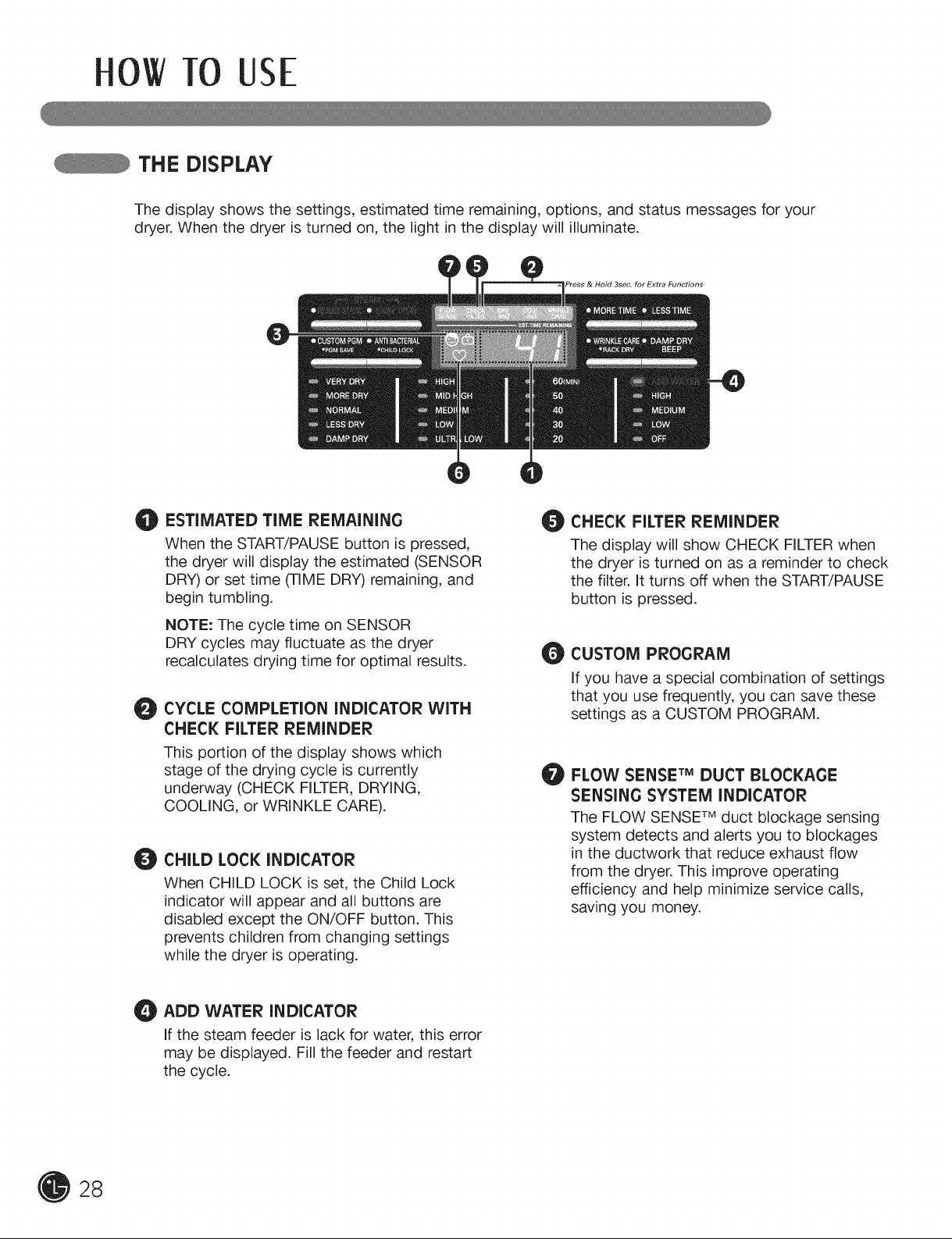
THE DISPLAY
The display shows the settings, estimated time remaining, options, and status messages for your
dryer. When the dryer is turned on, the light in the display will illuminate.
>ress & Hold 3sec. for Extra Functions
O
ESTIMATED TIME REMAINING
0
When the START/PAUSE button is pressed,
the dryer will display the estimated (SENSOR
DRY) or set time (TIME DRY) remaining, and
begin tumbling.
NOTE: The cycle time on SENSOR
DRY cycles may fluctuate as the dryer
recalculates drying time for optimal results.
CYCLE COMPLETION INDICATOR WITH
0
CHECK FILTER REMINDER
This portion of the display shows which
stage of the drying cycle is currently
underway (CHECK FILTER, DRYING,
COOLING, or WRINKLE CARE).
CHILD LOCK INDICATOR
When CHILD LOCK is set, the Child Lock
indicator will appear and all buttons are
disabled except the ON/OFF button. This
prevents children from changing settings
while the dryer is operating.
O CHECK FILTER REMINDER
The display will show CHECK FILTER when
the dryer is turned on as a reminder to check
the filter. It turns off when the START/PAUSE
button is pressed.
CUSTOM PROGRAM
If you have a special combination of settings
that you use frequently, you can save these
settings as a CUSTOM PROGRAM.
FLOW SENSE TM DUCT BLOCKAGE
O
SENSING SYSTEM INDICATOR
The FLOW SENSE TM duct blockage sensing
system detects and alerts you to blockages
in the ductwork that reduce exhaust flow
from the dryer. This improve operating
efficiency and help minimize service calls,
saving you money.
28
ADD WATER INDICATOR
if the steam feeder is lack for water, this error
may be displayed. Fill the feeder and restart
the cycle.
rio TO USE
OPERATING THE DRYER
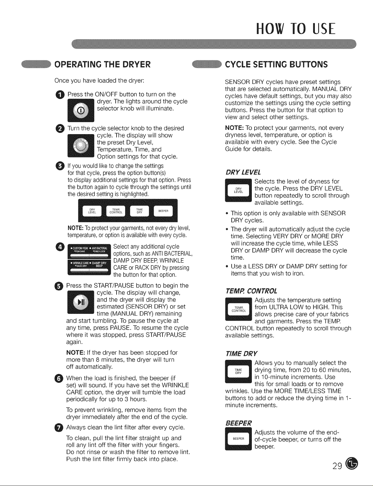
Once you have loaded the dryer:
O Press the ON/OFF button to turn the
dryer. The lights around the cycle
selector knob will illuminate.
O Turn the selector knob to the desired
O Ifyou to change settings
for that cycle, press the option button(s)
to display additional settings for that option. Press
the button again to cycle through the settings until
the desiredsetting ishighlighted.
NOTE:Toprotectyourgarments,noteverydry level,
temperature,or option isavailablewith everycycle.
@
cycle
cycle. The display will show
the preset Dry Level,
Temperature, Time, and
Option settings for that cycle.
would like the
Select any additional cycle
options,suchasANTI BACTERIAL,
DAMP DRYBEERWRINKLE
CAREor RACKDRYby pressing
the button for that option.
on
CYCLE SETTING BUTTONS
SENSOR DRY cycles have preset settings
that are selected automatically. MANUAL DRY
cycles have default settings, but you may also
customize the settings using the cycle setting
buttons. Press the button for that option to
view and select other settings.
NOTE: To protect your garments, not every
dryness level, temperature, or option is
available with every cycle. See the Cycle
Guide for details.
DRY LEVEL
Selects the level of dryness for
the cycle. Press the DRY LEVEL
button repeatedly to scroll through
available settings.
• This option is only available with SENSOR
DRY cycles.
The dryer will automatically adjust the cycle
time. Selecting VERY DRY or MORE DRY
will increase the cycle time, while LESS
DRY or DAMP DRY will decrease the cycle
time.
Use a LESS DRY or DAMP DRY setting for
items that you wish to iron.
O Press the START/PAUSE button to begin the
cycle. The display will change,
and the dryer will display the
estimated (SENSOR DRY) or set
time (MANUAL DRY) remaining
and start tumbling. To pause the cycle at
any time, press PAUSE. To resume the cycle
where it was stopped, press START/PAUSE
again.
NOTE: If the dryer has been stopped for
more than 8 minutes, the dryer will turn
off automatically.
When the load is finished, the beeper (if
O
set) will sound. If you have set the WRINKLE
CARE option, the dryer will tumble the load
periodically for up to 3 hours.
To prevent wrinkling, remove items from the
dryer immediately after the end of the cycle.
Always clean the lint filter after every cycle.
O
To clean, pull the lint filter straight up and
roll any lint off the filter with your fingers.
Do not rinse or wash the filter to remove lint.
Push the lint filter firmly back into place.
TEMP. CONTROL
Adjusts the temperature setting
from ULTRA LOW to HIGH. This
allows precise care of your fabrics
and garments. Press the TEMR
CONTROL button repeatedly to scroll through
available settings.
TIME DRY
Allows you to manually select the
drying time, from 20 to 60 minutes,
in 10-minute increments. Use
this for small loads or to remove
wrinkles. Use the MORE TIME/LESS TIME
buttons to add or reduce the drying time in 1-
minute increments.
BEEPER
Adjusts the volume of the end-
of-cycle beeper, or turns off the
beeper.
29
OWTO USE
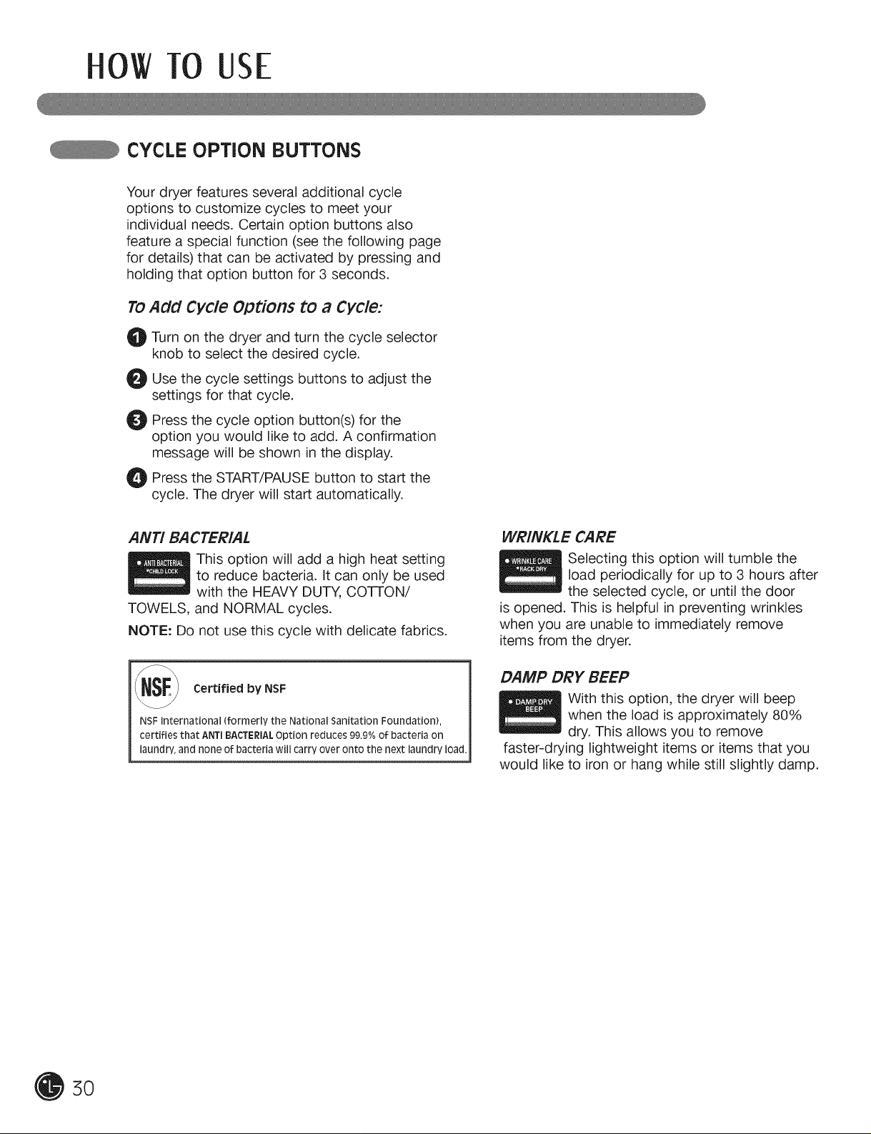
CYCLE OPTION BUTTONS
Your dryer features several additional cycle
options to customize cycles to meet your
individual needs. Certain option buttons also
feature a special function (see the following page
for details) that can be activated by pressing and
holding that option button for 3 seconds.
TO
Add Cycle Options to a Cycle:
0
Turn on the dryer and turn the cycle selector
knob to select the desired cycle.
0
Use the cycle settings buttons to adjust the
settings for that cycle.
0
Press the cycle option button(s) for the
option you would like to add. A confirmation
message will be shown in the display.
O Press the START/PAUSE button start the
cycle. The dryer will start automatically.
to
ANTI BACTERIAL
This option will add a high heat setting
to reduce bacteria. It can only be used
with the HEAVY DUTY, Co-IrON/
TOWELS, and NORMAL cycles.
NOTE: Do not use this cycle with delicate fabrics.
SF_J Certified by NSF
NSF International (formerly the National Sanitation Foundation),
certifies that ANTIBACTERIALOption reduces 99.9%of bacteria on
laundry, and none of bacteria will carry over onto the next laundry load.
WRINKLE CARE
Selecting this option will tumble the
load periodically for up to 3 hours after
the selected cycle, or until the door
is opened. This is helpful in preventing wrinkles
when you are unable to immediately remove
items from the dryer.
DAMP DRY BEEP
With this option, the dryer will beep
when the load is approximately 80%
dry. This allows you to remove
faster-drying lightweight items or items that you
would like to iron or hang while still slightly damp.
5O
 Loading...