

LG DLG7061VE User Manual

ENGLISH ESPAÑOL
OWNER’S MANUAL
DRYER
Read this owner’s manual thoroughly before operating the appliance
and keep it handy for reference at all times.
DLE7060*E (Elec)
DLG7061*E (Gas)
MFL70442639
Rev.00_071519
Copyright © 2019 LG Electronics Inc. All Rights Reserved.
www.lg.com

2
TABLE OF CONTENTS
TABLE OF CONTENTS
PRODUCT FEATURES
3
SAFETY INSTRUCTIONS
4
5 IMPORTANT SAFETY INSTRUCTIONS
7 GROUNDING INSTRUCTIONS
PRODUCT OVERVIEW
8
8 Parts
8 Accessories
8 Safety Tether Kit
8 Two-Way Reversible Door (on some models)
INSTALLATION
9
9 Installation Overview
9 Product Specifications
10 Installation Location Requirements
10 Clearances
12 Leveling the Dryer
12 Reversing the Door
20 Installing the Side Vent Kit
21 Venting the Dryer
23 Connecting Gas Dryers
25 Connecting Electric Dryers
29 Final Installation Check
30 Installation Test (Duct Check)
SMART FUNCTIONS
41
41 Smart Diagnosis™ Function
MAINTENANCE
42
42 Regular Cleaning
TROUBLESHOOTING
43
43 FAQs: Frequently Asked Questions
43 User Support Videos
44 Before Calling for Service
WARRANTY (USA)
51
OPERATION
32
32 Using the Dryer
33 Check the Lint Filter Before Every Load
33 Sorting Loads
33 Loading the Dryer
34 Using the LG EasyLoad
35 Control Panel
37 Cycle Guide
39 Cycle Settings and Options
TM
PRODUCT FEATURES
ENGLISH
C
E
R
T
I
F
I
E
D
D
E
S
I
G
N
T
I
F
3
PRODUCT FEATURES
Easy-to-Use Control Panel
An entire selection of user-friendly functions make operating the dryer easy.
Two-Way Easy-Access Reversible Door
The LG EasyLoadTM can be tilted open from the top, hamper-style, allowing you to easily load the dryer without items falling
on the floor. The door still swings open to provide easy access for unloading or loading of bulkier items. The door hinge can
be reversed to adjust to the installation location.
Flow SenseTM Duct Blockage Sensing System Indicator
The Flow SenseTM duct blockage sensing system detects and alerts you to restrictions in the installed household ductwork
that reduce exhaust airflow through the dryer. If you see the alert: Clean or repair the ducts to remove the restrictions. Keep
your ducts free of blockage to help increase efficiency and reduce long drying times caused by blocked ducts.
Smart Diagnosis™
Should you experience any technical difficulty with your dryer, it has the capability of transmitting data via your telephone
to the Customer Information Center. The call center agent records the data transmitted from your machine and uses it to
analyze the issue, providing a fast and effective diagnosis.
I
G
S
N
E
D
C
E
D
R
E
I
4
SAFETY INSTRUCTIONS
SAFETY INSTRUCTIONS
READ ALL INSTRUCTIONS BEFORE USE
Your safety and the safety of others is very important.
We have provided many important safety messages in this manual and on your appliance. Always read and
obey all safety messages.
This is the safety alert symbol.
This symbol alerts you to potential hazards that can kill or hurt you and others.
All safety messages will follow the safety alert symbol and either the word DANGER, WARNING, or
CAUTION.
These words mean:
-
DANGER
You will be killed or seriously injured if you
do not
immediately follow instructions.
WARNING
CAUTION
All safety messages will tell you what the potential hazard is, tell you how to reduce the chance of injury,
and tell you what may happen if the instructions are not followed.
- You may be killed or seriously injured if you do not follow instructions.
- You may be slightly injured or cause damage to the product if you do not follow
instructions.
WARNING – Risk of Fire
Install the clothes dryer according to the manufacturer’s instructions and local codes.
•Do not install a clothes dryer with flexible plastic venting materials. If flexible metal (foil type) duct is installed,
it must be of a specific type identified by the appliance manufacturer as suitable for use with clothes dryers.
Flexible venting materials are known to collapse, be easily crushed, and trap lint. These conditions will obstruct
clothes dryer airflow and increase the risk of fire.
•To reduce the risk of severe injury or death, follow all installation instructions.
•Save these instructions.
WARNING
FIRE OR EXPLOSION HAZARD
Failure to follow safety warnings exactly could result in serious injury, death or property damage.
—Do not store or use gasoline or other flammable vapors and liquids in the vicinity of this or any other
appliance.
—WHAT TO DO IF YOU SMELL GAS
• Do not try to light any appliance.
• Do not touch any electrical switch; do not use any phone in your building.
• Clear the room, building or area of all occupants.
• Immediately call your gas supplier from a neighbor’s phone. Follow the gas supplier’s instructions.
• If you cannot reach your gas supplier, call the fire department.
—Installation and service must be performed by a qualified installer, service agency or the gas supplier.

SAFETY INSTRUCTIONS
ENGLISH
5
IMPORTANT SAFETY INSTRUCTIONS
WARNING
To reduce the risk of fire, electric shock, or injury to persons when using your appliance, follow basic
precautions, including the following:
Installation
•Keep area around the exhaust opening and adjacent
surrounding areas free from the accumulation of lint,
dust, and dirt.
•Do not install or store this appliance where it will be
exposed to the weather.
Do not place items exposed to cooking oils in
•
your dryer.
contribute to a chemical reaction that could cause a
load to catch fire.
Properly ground the dryer to conform with all
•
governing codes and ordinances.
in the installation instructions. Electric shock may result
if the dryer is not properly grounded.
Before use, the dryer must be properly installed as
•
described in this manual.
the dryer is not properly grounded.
•Install and store the dryer where it will not be exposed to
temperatures below freezing or exposed to the weather.
All repairs and servicing must be performed by
•
authorized service personnel unless specifically
recommended in this Owner’s Manual. Use only
authorized factory parts.
may result in serious injury, fire, electric shock, or death.
To reduce the risk of electric shock, do not install
•
the dryer in humid spaces.
warning may result in serious injury, fire, electric shock,
or death.
Connect to a properly rated, protected, and sized
•
power circuit to avoid electrical overload.
power circuits may melt, creating electric shock and/or
fire hazard.
Remove all packing items and dispose of all
•
shipping materials properly.
result in burns, fire, explosion, or death.
Place the dryer at least 18 inches (45.7 cm) above
•
the floor for a garage installation.
may result in burns, fire, explosion, or death.
Keep all packaging from children.
•
can be dangerous for children. There is a risk of
suffocation.
Do not install near another heat source such as a
•
stove, oven or heater.
may result in product deformation, smoke, or fire.
•Do not place candles, smoking materials, or other
flammables on top of the product. Dripping wax, smoke,
or fire may result.
Items contaminated with cooking oils may
Follow the details
Electric shock may result if
Failure to follow this warning
Failure to follow this
Improper
Failure to do so may
Failure to do so
Packaging material
Failure to follow this warning
Remove all protective vinyl film from the product.
•
Failure to do so may result in product damage, smoke,
or fire.
Gas dryers MUST be exhausted to the outside.
•
Failure to follow these instructions may result in fire or
death.
•The dryer exhaust system must be exhausted to the
outside of the dwelling. If the dryer is not exhausted
outdoors, some fine lint and large amounts of moisture
will be expelled into the laundry area. An accumulation
of lint in any area of the home may create a health and
fire hazard.
•Use only rigid, semi-rigid or flexible metal 4-inch
(10.2 cm) diameter duct inside the dryer cabinet or
for exhausting to the outside. Use of plastic or other
combustible ductwork may cause a fire. Punctured
ductwork may cause a fire if it collapses or becomes
otherwise restricted in use or during installation.
Ductwork is not provided with the dryer, and you
•
should obtain the necessary ductwork locally. The
end cap should have hinged dampers to prevent
backdraft when the dryer is not in use.
follow these instructions may result in fire or death.
The exhaust duct must be 4 inches (10.2 cm) in
•
diameter with no obstructions. The exhaust duct
should be kept as short as possible. Make sure to
clean old ducts before installing your new dryer.
Failure to follow these instructions may result in fire or
death.
Rigid, semi-rigid or flexible metal ducting is
•
recommended for use between the dryer and the
wall. All non-rigid metal transition duct must be
UL-listed. Use of other materials for transition
duct could affect drying time.
instructions may result in fire or death.
Do not use sheet metal screws or other fasteners
•
which extend into the duct that could catch lint and
reduce the efficiency of the exhaust system. Secure
all joints with duct tape. For complete details, follow
the Installation Instructions.
instructions may result in fire or death.
•Certain internal parts are intentionally not grounded
and may present a risk of electronic shock only
during servicing.
Service personnel - do not contact the following
parts while the appliance is energized: CONTROL
BOARD
Failure to follow these
Failure to follow these
Failure to

6
SAFETY INSTRUCTIONS
Operation
•Read all instructions before using the appliance.
•Do not dry articles that have been previously
cleaned in, washed in, soaked in, or spotted with
gasoline, dry-cleaning solvents, or other flammable
or explosive substances, as they give off vapors
that could ignite or explode.
•Do not reach into the appliance if the drum is
moving.
•Do not allow children to play on or in the appliance.
Close supervision of children is necessary when
the appliance is used near children.
•Do not use fabric softeners or products to eliminate
static unless recommended by the manufacturer of
the fabric softener or product.
•Do not use heat to dry articles containing foam
rubber or similarly textured rubber-like materials.
•Do not tamper with controls.
•Always check the inside of the dryer for foreign
objects. Failure to follow these instructions may
result in fire or death.
•Do not store plastic, paper, or clothing that may
burn or melt on top of the dryer during operation.
Failure to follow these instructions may result in fire
or death.
•Be careful when opening and closing the door.
Fingers and hands can get caught in the door and
cause injury if the door drops forward unexpectedly.
Do not place heavy items on or lean against the
•
top of the door when it is open.
Do not attempt to pull the hamper door open
•
more than 40 degrees.
forward, causing injury or damage.
•Do not place items on the top of the dryer.
•Do not put animals, such as pets into the appliance.
•Gas appliances can cause minor exposure to four
potentially hazardous substances, namely benzene,
carbon monoxide, formaldehyde, and soot, caused
primarily by the incomplete combustion of natural
gas or LP fuels.
•Properly adjusted dryers will minimize incomplete
combustion. Exposure to these substances can be
minimized further by properly venting the dryer to
the outdoors.
•Do not place items exposed to cooking oils in your
dryer. Items contaminated with cooking oils may
contribute to a chemical reaction that could cause a
load to catch fire.
To reduce the risk of fire due to contaminated loads,
the final part of a tumble dryer cycle occurs without
heat (cool down period). Avoid stopping a tumble
dryer before the end of the drying cycle unless all
items are quickly removed and spread out so that
the heat is dissipated.
•Do not let children or pets climb inside the dryer
drum.
•Do not put living animals such as pets inside the
product.
The dryer could tip
SAVE THESE INSTRUCTIONS
•Do not put any part of your body, such as your
hands or feet, or metal objects under the product.
•Do not let your hand get pinched when opening or
closing the dryer door.
Steam (steam model):
Do not open the dryer door during steam
•
cycles.
result in a burn hazard.
Do not dry articles that have been previously
•
cleaned in, washed in, soaked in, or spotted
with gasoline, dry-cleaning solvents, or other
flammable or explosive substances as they give
off vapors that could ignite or explode.
follow these instructions may result in fire or death.
Do not fill the steam feeder with gasoline,
•
dry cleaning solvents, or other flammable or
explosive substances.
instructions may result in fire or death.
Do not touch the steam nozzle in the drum
•
during or after the steam cycles.
these instructions may result in a burn hazard.
Do not fill the steam feeder with hot water (over
•
86 °F/30 °C).
may result in a burn hazard.
Maintenance
•Do not repair or replace any part of the appliance
or attempt any servicing unless specifically
recommended in the user maintenance instructions
or in published user-repair instructions that you
understand and have the skills to carry out.
•Clean the lint filter before or after each load.
•The interior of the appliance and exhaust duct
should be cleaned periodically by qualified service
personnel.
•Before the appliance is removed from service
or discarded, remove the door to the drying
compartment.
•Certain internal parts are intentionally not grounded
and may present a risk of electronic shock only
during servicing.
Service personnel - do not contact the following
parts while the appliance is energized: CONTROL
BOARD
Failure to follow these instructions may
Failure to
Failure to follow these
Failure to follow
Failure to follow these instructions
WARNING
Fire Hazard
Failure to follow safety warnings exactly could
result in serious injury, death or property damage.
Do not install a booster fan in the exhaust duct.
Install all clothes dryers in accordance with the
installation instructions of the manufacturer of the
dryer.

SAFETY INSTRUCTIONS
ENGLISH
7
GROUNDING INSTRUCTIONS
WARNING
Improper connection of the equipment-grounding conductor may result in a risk of electric shock.
Check with a qualified electrician or service person if you are in doubt that the appliance is properly
grounded.
This appliance must be grounded.
•
of malfunction or breakdown, grounding will reduce
the risk of electric shock by providing a path of least
resistance for electric current.
This appliance must be equipped with a cord
•
having an equipment-grounding conductor and
a grounding plug.
an appropriate outlet that is properly installed and
grounded in accordance with all local codes and
ordinances.
Do not modify the plug.
•
have a proper outlet installed by a qualified
electrician.
This appliance must be connected to a
•
grounded metal, permanent wiring system or
an equipment-grounding conductor must be
run with the circuit conductors and connected
to the equipment-grounding terminal or lead
on the appliance.
dryer is not properly grounded.
The dryer should always be plugged into its
•
own individual electrical outlet which has a
voltage rating that matches the rating plate.
provides the best performance and also prevents
overloading house wiring circuits which can cause
a fire hazard from overheated wires.
Never unplug the dryer by pulling on the power
•
cord. Always grip the plug firmly and pull
straight out from the outlet.
be damaged, resulting in a risk of fire and electric
shock.
Repair or replace immediately all power
•
cords that have become frayed or otherwise
damaged. Do not use a cord that shows cracks
or abrasion damage along its length or at either
end.
The power cord may melt, creating electric
shock and/or fire hazard.
When installing or moving the dryer, be careful
•
not to pinch, crush, or damage the power cord.
This will prevent injury and damage to the dryer
from fire and electric shock.
The plug must be plugged into
If it will not fit the outlet,
Electric shock may result if the
In the event
The power cord may
This
Do not, under any circumstances, cut or
•
remove the ground prong from the power cord.
To prevent personal injury or damage to the dryer,
the electrical power cord must be plugged into a
properly grounded outlet.
For personal safety, this dryer must be properly
•
grounded.
shock or injury.
Refer to the installation instructions in this
•
manual for specific electrical requirements for
your model.
may create an electric shock hazard and/or a fire
hazard.
This dryer must be plugged into a properly
•
grounded outlet. Electrical shock may result if
the dryer is not properly grounded. Have the
wall outlet and circuit checked by a qualified
electrician to make sure the outlet is properly
grounded.
may create an electric shock hazard and/or a fire
hazard.
Failure to do so may result in electric
Failure to follow these instructions
Failure to follow these instructions
8
PRODUCT OVERVIEW
PRODUCT OVERVIEW
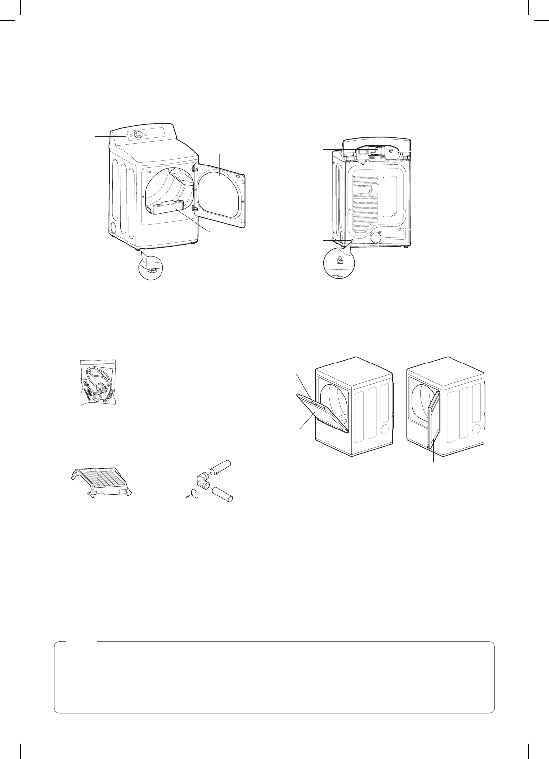
Parts
Control
panel
Leveling
feet
Accessories
Included Accessories
Safety Tether Kit
(on some models)
Optional Accessories
Reversible
door
Lint lter
Terminal block
access panel
(electric models)
Gas connection
location
(gas models)
Exhaust duct
outlet
Two-Way Reversible Door
(on some models)
Release
Hamper
door
Power cord
location
(gas models)
Water inlet valve
(on some models)
Swing door
The LG EasyLoad™ feature allows you to open the
dryer door from the top, hamper-style, when loading the
Drying rack
(sold separately)
No. 3750EL0001C
Side vent kit
(sold separately)
Kit No. 383EEL9001B
dryer to help guide clothes into the drum and prevent
them from falling onto the floor. When unloading the
dryer or loading bulkier items, use the swing door for
easy access to the drum.
Safety Tether Kit
This optional kit helps prevent the dryer tipping if children climb on the door or if someone should fall onto the
door. It is recommended that you install this kit, depending on your situation, but it is not required. Follow the
customer installation instructions included with the kit to properly install the kit. If you do not install the kit, store it
out of reach of children.
NOTE
•For your safety and for extended product life, use only authorized components. The manufacturer is not
responsible for product malfunction or accidents caused by the use of separately purchased unauthorized
components or parts.
•The images in this guide may be different from the actual components and accessories, which are subject
to change by the manufacturer without prior notice for product improvement purposes.
INSTALLATION
ENGLISH
9
INSTALLATION
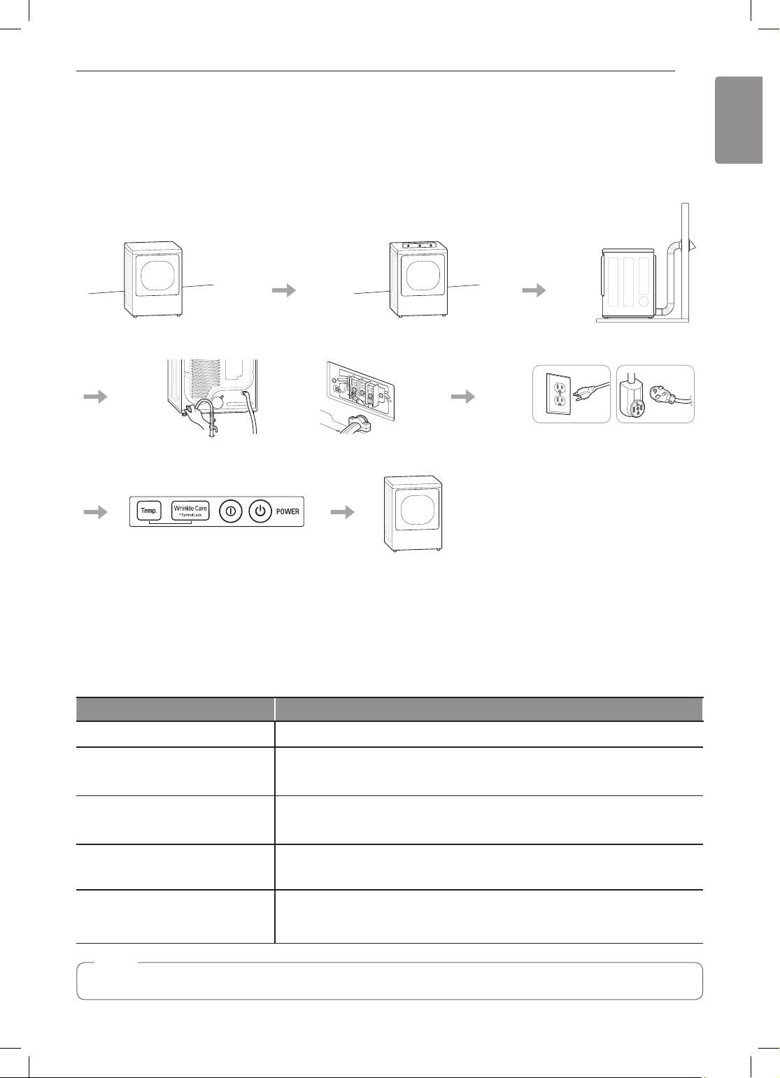
Installation Overview
Please read the following installation instructions first after purchasing this product or transporting it to another
location.
Check and choose
the proper location
Connect gas dryers
Connect electric dryers
Level the dryer
Vent the dryer
Gas dryer Electric dryer
Plug in the power cord
Installation test Test run
Product Specifications
The appearance and specifications listed in this manual may vary due to constant product improvements.
Dryer Models DLE7060*E, DLG7061*E
Electrical requirements
Gas requirements
Dimensions
Net weight
Drying capacity
- Normal cycle
NOTE
Model numbers can be found on the cabinet inside the door.
Please refer to the rating label regarding detailed information.
NG: 4–10.5-inch WC
LP: 8–13-inch WC
27” (W) X 29 1/2” (D) X 44 1/4” (H), 50 1/4” (D with door open)
68.6 cm (W) X 75.0 cm (D) X 112.3 cm (H), 127.5 cm (D with door open)
Gas dryer : 124.4 lb (56.4 Kg)
Electric dryer : 121.3 lb (55 Kg)
IEC 7.3 cu.ft. (22.5 lb/10.2 kg)

10
INSTALLATION
Installation Location Requirements
WARNING
Read all installation instructions completely before installing and operating the dryer! It is important that you
review this entire manual before installing and using the dryer. Detailed instructions concerning electrical
connections, gas connections, and exhaust requirements are provided on the following pages.
The installation requires:
•A location that allows for proper exhaust installation. A gas dryer must be exhausted to the outdoors. See
Venting the Dryer.
•A grounded electrical outlet located within 2 ft. (61 cm) of either side of the dryer. See Connecting Electric
Dryers .
•A sturdy floor to support the total dryer weight of 200 lb (90.7 kg). The combined weight of a companion
appliance should also be considered.
•No other fuel-burning appliance can be installed in the same closet as a dryer.
Do not operate the dryer at temperatures below 45 °F (7 °C). At lower temperatures, the dryer might not shut off
at the end of an automatic cycle. This can result in longer drying times. The dryer must not be installed or stored
in an area where it will be exposed to water and/or weather. Check code requirements. Some codes limit, or do
not permit, installation of the dryer in garages, closets, mobile homes or sleeping quarters. Contact your local
building inspector.
NOTE
•The floor must be level, with a maximum slope of 1 inch (2.5 cm) under the entire dryer.
Clothes may not tumble properly, and automatic sensor cycles may not operate correctly if dryer is not
level.
•For a garage installation, you will need to place the dryer at least 18 inches (46 cm) above the floor. The
standard pedestal is 15 inches (38.1 cm). You will need 18 inches (46 cm) from the garage floor to the
bottom of the dryer.
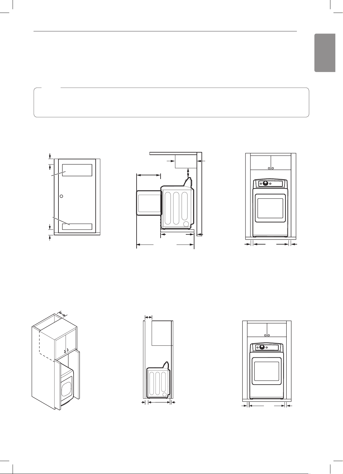
Clearances
Installation Spacing for Recessed Area or Closet Installation
The following spacing dimensions are recommended for this dryer. This dryer has been tested for clearances of
1 inch (2.5 cm) on the sides and rear. Recommended clearances should be considered for the following reasons:
•Additional clearances should be considered for ease of installation and servicing.
•Additional clearances might be required for wall, door and floor moldings.
•Additional clearances should be considered on all sides of the dryer to reduce noise transfer.
For closet installation, with a door, minimum ventilation openings in the top and bottom of the door are
required. Louvered doors with equivalent ventilation openings are acceptable.
•Companion appliance spacing should also be considered.
INSTALLATION
ENGLISH
Closet Ventilation Requirements
Closets with doors must have both an upper and lower vent to prevent heat and moisture buildup in the closet.
One upper vent opening with a minimum opening of 48 sq. in. (310 cm2) must be installed no lower than 6 feet
above the floor. One lower vent opening with a minimum opening of 24 sq. in. (155 cm2) must be installed no
more than one foot above the floor. Install vent grills in the door or cut down the door at the top and bottom to
form openings. Louvered doors with equivalent ventilation openings are also acceptable.
NOTE
There should be at least a little space around the dryer (or any other appliance) to eliminate the transfer of
vibration from one appliance to another. If there is enough vibration, it could cause appliances to make noise
or come into contact, causing paint damage and further increasing noise.
Installation Spacing for Recessed Area or Closet
3"
(7.6 cm)
14" max.*
(35.6 cm)
18" min.
(45.7 cm)
2
48 in.
(310 cm2)
1
21
/4"
(54 cm)
11
2
24 in.
(155 cm2)
1
/2"
29
(75.0 cm)
1
/4"
50
(127.5 cm)
1"
(2.5 cm)
27"
(68.6 cm)
3"
(7.6 cm)
Closet Door Vent
Requirements
* Required spacing
Installation Spacing for Cabinet
For cabinet installation with a door, minimum ventilation openings in the top of the cabinet are required.
* Required spacing
7"* (17.8 cm)
7"* (17.8 cm)
1"
(2.5 cm)
5"
(12.7 cm)
*
1
/2"
29
(75.0 cm)
1"
*
(2.5 cm)
(2.5 cm)
1"
27"
(68.6 cm)
1"
(2.5 cm)
12
INSTALLATION
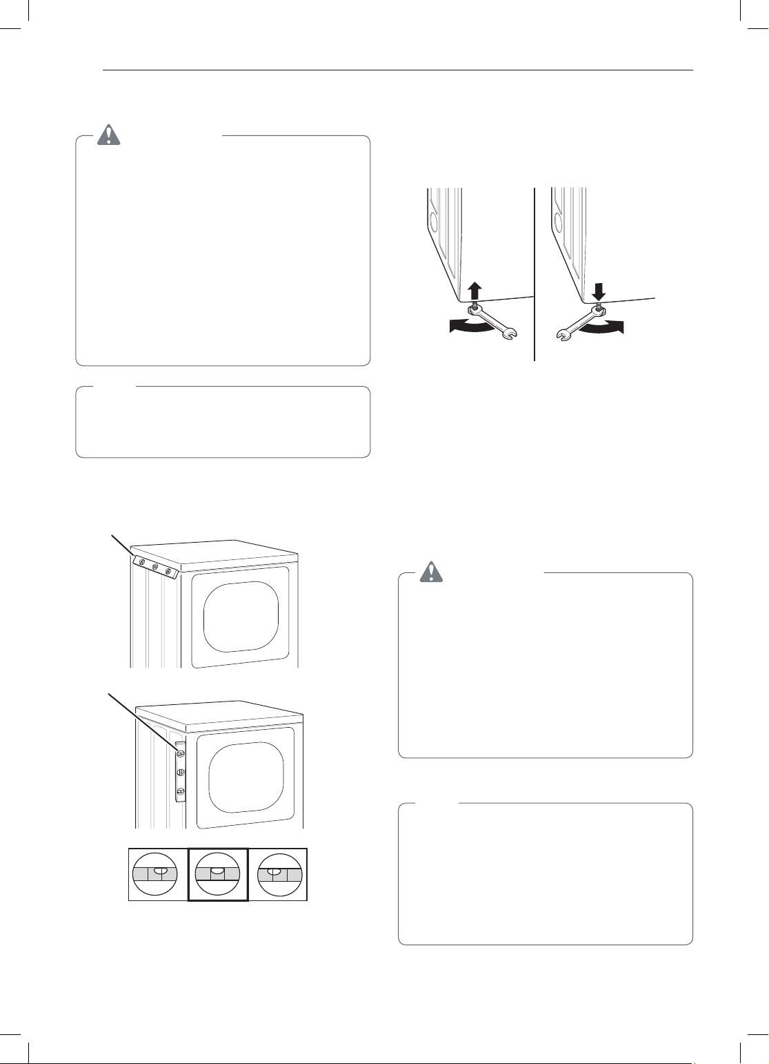
Leveling the Dryer
WARNING
To reduce the risk of injury to persons, adhere
to all industry recommended safety procedures
including the use of long-sleeved gloves and
safety glasses. Failure to follow this warning may
result in serious injury or death.
•The appliance is heavy. Two or more people
are required when installing the dryer. Failure to
follow this warning may result in serious injury
or death.
•To ensure that the dryer provides optimal drying
performance, it must be level. To minimize
vibration, noise, and unwanted movement, the
floor must be a perfectly level, solid surface.
NOTE
Adjust the leveling feet only as far as necessary
to level the dryer. Extending the leveling feet more
than necessary may cause the dryer to vibrate.
Position the dryer in the final location. Check
1
levelness of dryer from side to side. Repeat from
front to back.
Place level here
Use an adjustable wrench to turn the leveling
2
feet. Unscrew the legs to raise the dryer or
screw in the legs to lower it. Raise or lower with
the leveling feet until the dryer is level from side
to side and front to back. Make sure that all four
leveling feet are in firm contact with the floor.
If you are installing the dryer on the optional pedestal,
you must use the leveling feet on the pedestal to level the
dryer. The dryer leveling feet should be fully retracted.
Reversing the Door
Tools Required
Phillips or large flat-blade screwdriver (for hinge screws)
Small flat-blade screwdriver (for lifting out parts)
Place level here
Not Level Not LevelLevel
WARNING
The dryer door is very large and heavy.
Failure to follow the instructions below can result
in damage to the dryer, property damage or
personal injury.
•To avoid damage to the dryer or the door,
support the door with a stool or box that fits
under the door, or have an assistant support
the weight of the door.
•Avoid dropping the door to prevent damage to
the door or the floor.
•Unplug the dryer or turn off power at the main
circuit breaker before beginning door reversal.
Door Reversal Instructions
NOTE
The instructions here are for changing the door
swing from a right to a left side hinge. If the
door has been reversed, and it is necessary to
change it back, use care when following these
instructions.
Some of the illustrations and the left/right
references will be reversed, and you will need to
read the instructions carefully.
INSTALLATION
ENGLISH
13
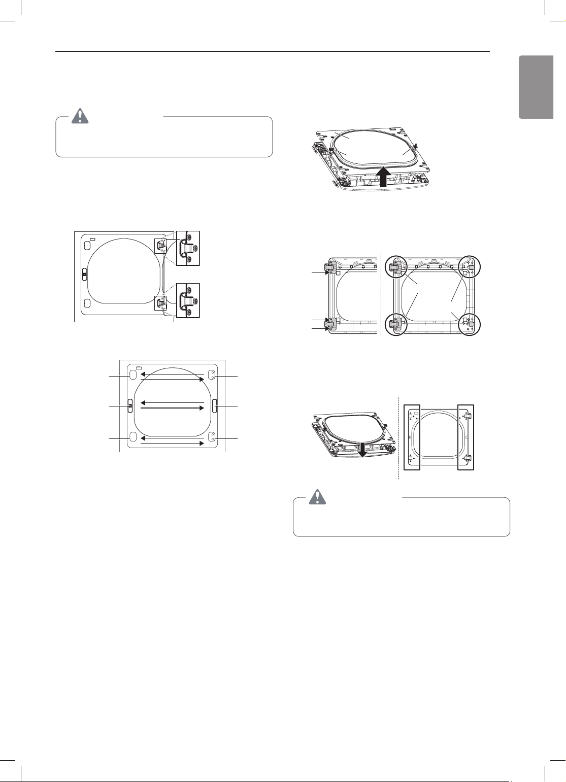
Swing door
Open the door from the side so that the hinge
1
screws are accessible.
WARNING
Be sure to support the weight of the door before
removing the hinge screws.
Remove the four hinge screws.
2
While supporting the door, remove the four hinge
screws, two from each hinge. Set the door aside
face down on a protected surface to prevent
damage to the door or the work surface.
Reverse the components on the cabinet.
3
hinge
cover
latch
mechanism
hinge
latch
hole
cover
With the door on a protected surface, remove all
4
screws on the sides of the door and lift off the
inner door frame using a flat blade screwdriver.
Remove the latch hook and blank and install
them on the opposite side.
Inner door
frame
Blank
Latch hook
Remove the 4 screws securing the hinges to
5
the door frame. Remove the two plastic cover
caps. Reinstall the hinges and cover caps on the
opposite sides from which they were removed.
Hinge
assembly
Cover cap
With the hinges and cover caps in the new
6
locations, remount the inner door frame onto the
outer door frame with the screws removed in
step 4 above.
hinge
cover
a. Use a Phillips screwdriver to remove the two
screws and the latch mechanism on the front
panel of the cabinet.
b. Remove the latch hole cover by gently prying it
up with a flat blade screwdriver, being careful
not to scratch the paint. Install the latch hole
cover on the opposite side, where the latch
mechanism was removed. Install the latch
mechanism in the position from which you
removed the latch hole cover, using the two
screws removed in step a.
c. Remove the hinge cover by gently prying it up
with a flat blade screwdriver, being careful not
to scratch the paint. Rotate the hinge cover
180 degrees and install it on the opposite side,
where the hinge was attached.
hinge
WARNING
Be sure to support the weight of the door before
installing the hinge screws.
14
INSTALLATION
Reinstall the door.
7
While supporting the door, install the four hinge
screws removed in step 2. Test the swing of
the door to make sure the hinges and latch are
properly aligned and that the door opens, closes
and latches properly.
Swing
Door
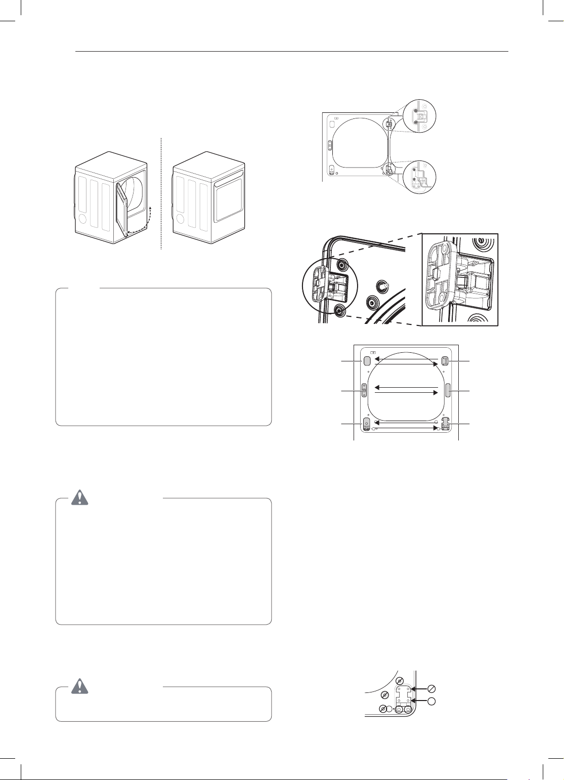
Easy LoadTM Door (on some models)
NOTE
The door reversal procedure for the Easy Load
door is far more complex than for a conventional
swing door. Read through these instructions in
their entirety before beginning the process, to
judge whether you prefer to have the procedure
done by a professional installer or service person.
The instructions here are for changing the door
swing from a right to a left side hinge. If the door
has been reversed, and it is necessary to change
it back, use care when following these instructions.
Some of the illustrations and the left/right
references will be reversed, and you will need to
read the instructions carefully.
Remove the door from cabinet.
2
a. While supporting the door, remove the four
hinge screws.
Two large
screws
Two small
screws
b. Lift the door slightly to disengage the hinge
support and remove the door from the cabinet.
Set the door aside face down on a protected
work surface.
Reverse the components on the cabinet.
3
Hinge
cover
latch
mechanism
Hinge
Upper
hinge
Latch
hole
cover
Hinge
bracket
Tools Required
Phillips or large flat-blade screwdriver (for hinge screws)
Small flat-blade screwdriver (for lifting out parts)
WARNING
The dryer door is very large and heavy.
Failure to follow the instructions below can result
in damage to the dryer, property damage or
personal injury.
•To avoid damage to the dryer or the door,
support the door with a stool or box that fits
under the door, or have an assistant support
the weight of the door.
•Avoid dropping the door to prevent damage to
the door or the floor.
•Unplug the dryer or turn off power at the main
circuit breaker before beginning door reversal.
ON THE CABINET :
Open the door from the side so that the hinge
1
screws are accessible.
WARNING
Be sure to support the weight of the door before
installing the hinge screws.
a. Use a Phillips screwdriver to remove the two
screws and the latch mechanism on the front
panel of the cabinet.
b. Remove the latch hole cover by gently prying it
up with a flat blade screwdriver, being careful
not to scratch the paint. Install the latch hole
cover on the opposite side, where the latch
mechanism was removed. Install the latch
mechanism in the position from which you
removed the latch hole cover, using the two
screws removed in step a.
c. Remove the hinge cover by gently prying it up
with a flat blade screwdriver, being careful not
to scratch the paint. Rotate the hinge cover
180 degrees and install it on the opposite side,
where the upper hinge was attached.
d. Reverse the hinge and the hinge bracket at
the bottom of the cabinet. Remove the two
screws from the hinge bracket at the bottom
right and remove the hinge bracket. Remove
the lower of the two screws behind the hinge
bracket. Do NOT remove the upper screw
behind the hinge bracket. Set the parts aside.
INSTALLATION
ENGLISH
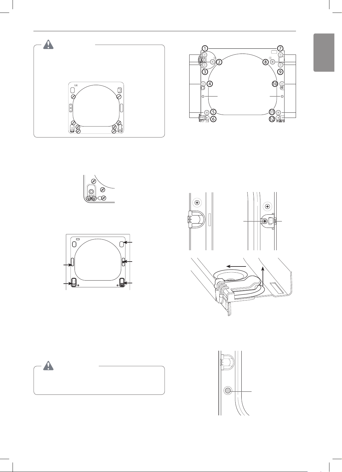
15
CAUTION
Do NOT remove any of the eight screws on the
face of the cabinet (marked below). Doing so
could result in damage to the dryer and the need
for a service call to repair the dryer.
e. Remove the three screws on the hinge at the
bottom left. Remove the hinge and reinstall it
on the right side. The top screw will occupy
the hole where you removed the screw behind
the hinge bracket in step d.
f. Install the hinge bracket removed in step d on
the bottom left side, first installing one screw
behind the hinge bracket.
Cabinet Reversal complete
Twelve screws
Hole
plug
Switch the door strike and the blank cover.
5
Remove the two screws on the door cover that
Side
Interlock
button
secure the door strike.
Switch the door strike and the blank cover,
installing them on the opposite sides from which
they were removed.
It may be difficult to insert the two screws in the
door strike on the opposite side. Use a cordless
screwdriver if necessary.
Short
screws
Long
screw
hinge
cover
latch hole
cover
hinge
bracket
latch
mechanism
hinge
ON THE DOOR:
Lift off the door cover.
4
With the door laid inside facing up on a protected
surface, remove the twelve screws on the
inside of the door. (The two bottom screws wil
be different from the rest.) Carefully lift off the
door cover with the help of a small flat blade
screwdriver inserted in the upper left corner.
WARNING
The edges of the door cover may be sharp. Take
care when handling, or wear gloves to avoid
injury.
Blank cover Door strike
Pull
Raise
Remove blank cover
Gently pry out the hole plug on the side of
the door cover and install it in the hole on the
opposite side.
Hole
plug
Set the door cover aside.
16
INSTALLATION
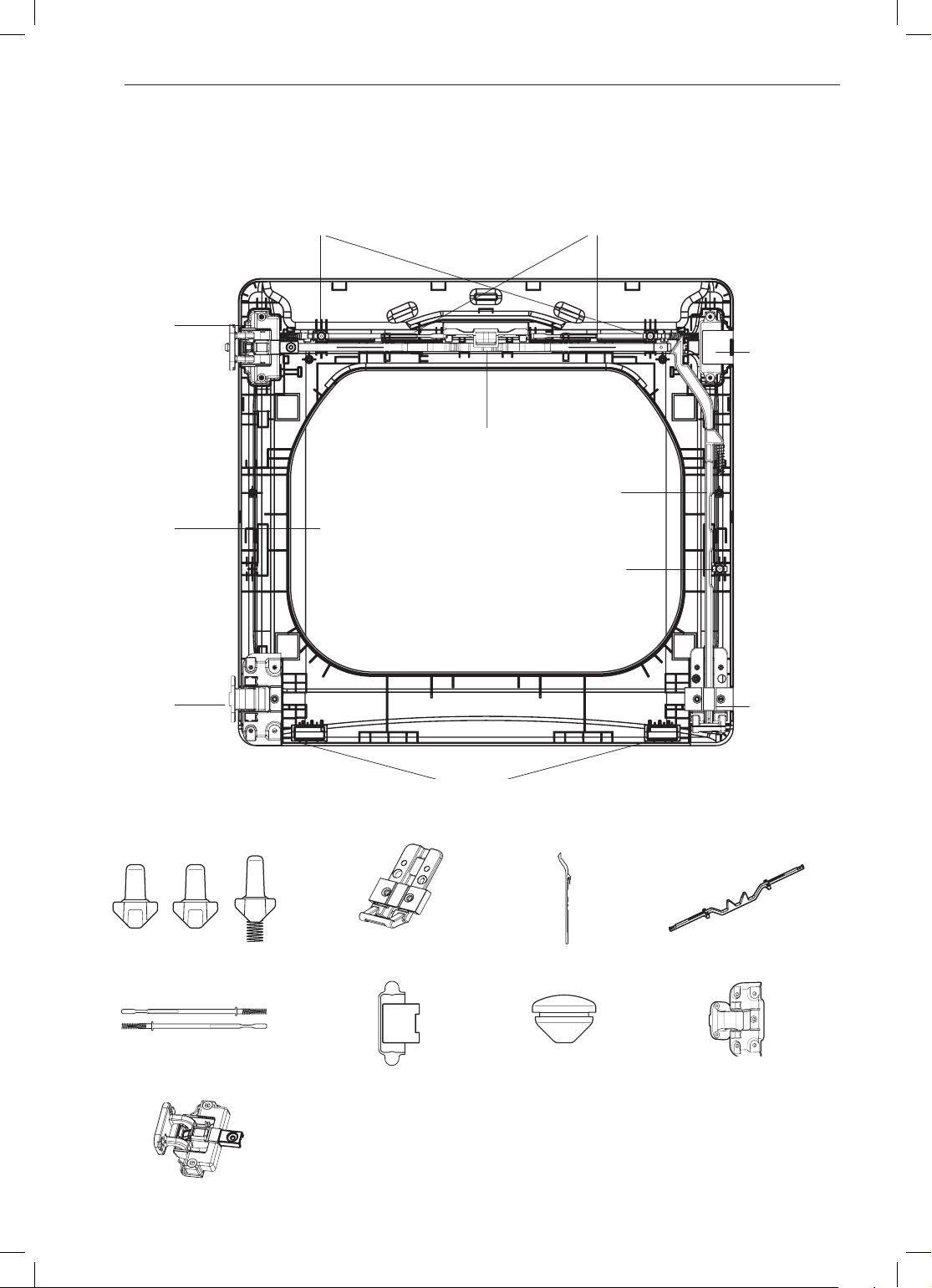
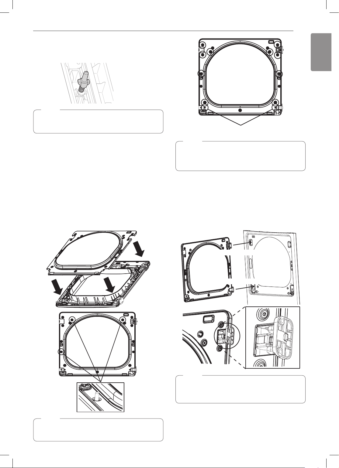
Reverse the components inside the door.
6
You will now be removing and reversing various components inside the door. See below for a detailed
diagram and identification of the inner structure and parts of the door. (The diagram shows the “before view”
of the door, with the default set-up for a right side hinge swing. After following these instructions, the door
should be a mirror image of the illustration.)
Inner lock rodsTop interlock buttons
Upper
hinge
assembly
Top lock rod
Side lock rod
Glass
Upper
hinge ller
Lower
hinge
assembly
Interlock buttons
Bumpers
Lower hinge bracket
Side Interlock button
Side lock rod
Lower
hinge
bracket
Top lock rod
Inner lock rods
Upper hinge assembly
Upper hinge ller
Hole plug
Lower hinge assembly
INSTALLATION
ENGLISH
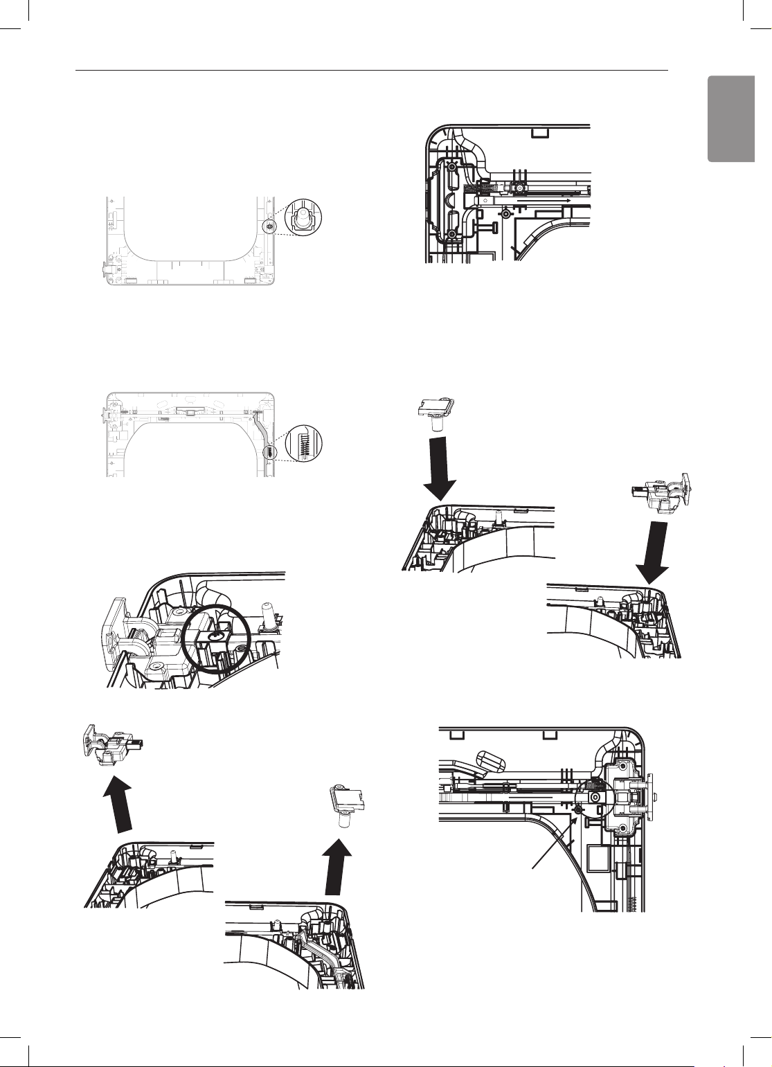
17
Lift out the gray interlock button in the side
7
of the door.
Make sure to remove the spring with the
interlock button and to keep the two together.
Set the interlock button aside. Do not confuse
this with the interlock buttons from the top of the
outer door.
Remove the side lock rod.
8
Remove the side lock rod from the lower hinge
bracket by lifting the top end of the rod and
sliding it toward the top of the door. The spring
should remain attached to the lock rod. Set the
lock rod aside.
Spring
c. Lift out the upper hinge assembly (on the left).
d. Slide the upper lock rod to the right. Rotate
the upper hinge assembly 180 degrees, and
install it over the lock rod on the right, where
you removed the upper hinge ller. Press
rmly to fully seat the hinge assembly.
e. Rotate the hinge ller 180 degrees and install
it on the upper left side of the door.
Reverse the upper hinge assembly and hinge
9
filler.
a. Remove the screw connecting the upper
hinge assembly to the top lock rod and set it
aside.
b. Lift out the upper hinge filler (on the right) and
set it aside.
f. Insert and tighten the screw connecting the
upper hinge assembly to the top lock rod,
removed in step a.
Assemble screw
18
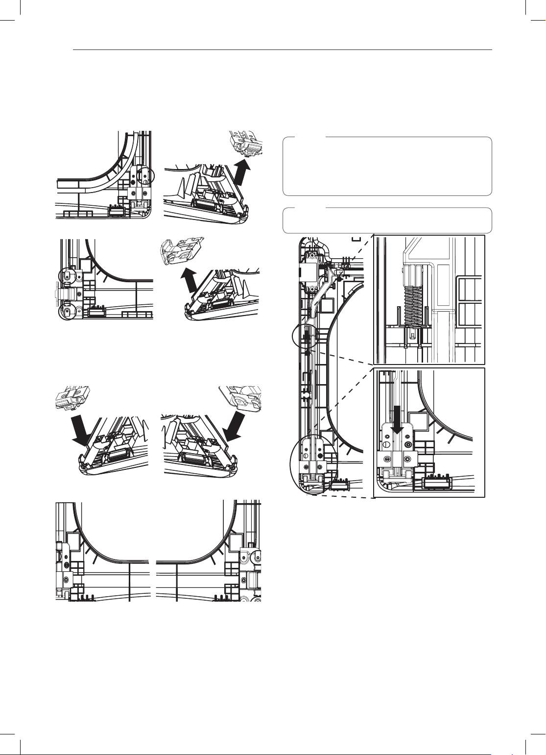
INSTALLATION
Reverse the lower hinge bracket and hinge
10
assembly.
a. Remove one screw from the lower hinge
bracket (on the right) and lift it out. Remove
two screws from the lower hinge assembly
(on the left) and lift it out.
b. Rotate the lower hinge assembly 180
degrees and install it on the right side using
the two screws removed in step a.
c. Mount the lower hinge bracket on the lower
left with the screw removed in step a.
Install the side lock rod.
11
a. Flip the side lock rod over and insert the
lower end into the left hinge bracket.
b. Lower the rod into the guides on the door
while compressing the spring inside the
recess.
NOTE
Make sure the top of the side lock rod is beside
the top lock rod and the two do not overlap each
other. If they are not aligned properly, the door will
not operate properly.
NOTE
Make sure the spring stays on the side lock rod.
INSTALLATION
ENGLISH
19
Reinstall the side interlock button.
12
Install the side interlock button on the opposite
side from which it was removed.
NOTE
Make sure the spring is on the interlock button
and is centered in the compartment.
Reinstall the door cover.
13
a. Clean the glass on the door and door cover,
if necessary.
b. Make sure the three gray interlock buttons
are properly installed and that the top and
side lock rods intersect properly.
c. Carefully lower the door cover into place,
aligning the holes in the cover with the three
interlock buttons and the bumpers on the
bottom edge. You may need to force fit the
door cover.
d. Once the door cover is in place, secure it
with the 12 screws removed in step 4.
Two different screws
NOTE
Ten similar screws are inserted in the top and
sides of the door cover. The two different screws
are inserted in the bottom edge.
Reassemble the door on cabinet.
14
While supporting the door, insert the hinge
support into the slot in the door and slide the
door down slightly to seat it. Install the four
hinge screws removed in step 2. Test the
swing of the door to check the alignment of the
hinges and latch. Make sure the door opens,
closes, and latches properly in both directions.
NOTE
Make sure the three interlock buttons are aligned
with the holes in the door cover.
Two large screws
Two small screws
NOTE
If the door is damaged, or if the door does not
work after reassembly, contact the call center at
1-800-243-0000.
20
INSTALLATION
Installing the Side Vent Kit
WARNING
•Use a heavy metal vent.
•Do not use plastic or thin foil ducts.
•Clean old ducts before installing this dryer.
•To reduce the risk of injury to persons, adhere
to all industry recommended safety procedures
including the use of long-sleeved gloves and
safety glasses.
•Failure to follow all of the safety warnings in this
manual could result in property damage, injury
to persons, or death.
The dryer is shipped to vent to the rear. It can also
be configured to vent to the bottom or side (right-side
venting is not available on gas models).
An adapter kit, part number 383EEL9001B, may be
purchased from an LG retailer. This kit contains the
necessary duct components to change the dryer vent
location.
Remove the rear exhaust duct retaining screw.
1
Pull out the exhaust duct.
Retaining Screw
Preassemble a 4-inch (10.2 cm) elbow to the
3
next 4-inch (10.2 cm) duct section, and secure
all joints with duct tape. Be sure that the male
end of the elbow faces AWAY from the dryer.
Insert the elbow/duct assembly through the
side opening and press it onto the adapter duct.
Secure it in place with duct tape. Be sure that
the male end of the duct protrudes 1½ inches
(3.8 cm) to connect the remaining ductwork.
Attach the cover plate to the back of the dryer
with the included screw.
Cover
Plate
Elbow
"
1
½
(3.8 cm)
Option 2: Bottom Venting
Press the adapter duct onto the blower housing
2
and secure it to the base of the dryer as shown.
Adapter
Duct
Rear Exhaust
Duct
Option 1: Side Venting
Press the tabs on the knockout and carefully
2
remove the knockout for the desired vent
opening (right-side venting is not available on
gas models). Press the adapter duct onto the
blower housing and secure to the base of the
dryer as shown.
Adapter
Duct
Bracket
Knockout
Bracket
Insert the 4-inch (10.2 cm) elbow through the
3
rear opening and press it onto the adapter duct.
Be sure that the male end of the elbow faces
down through the hole in the bottom of the
dryer. Secure it in place with duct tape. Attach
the cover plate to the back of the dryer with the
included screw.
Cover
Plate
Elbow
ENGLISH
Venting the Dryer
WARNING
To reduce the risk of fire or explosion, electric
shock, property damage, injury to persons or
death when using this appliance, follow basic
safety precautions, including the following:
Do not crush or collapse ductwork.
•
follow these instructions may result in fire or death.
Do not allow ductwork to rest on or contact
•
sharp objects.
Failure to follow these instructions
may result in fire or death.
If connecting to existing ductwork, make sure it
•
is suitable and clean before installing the dryer.
Failure to follow these instructions may result in fire
or death.
Venting must conform to local building codes.
•
Failure to follow these instructions may result in fire
or death.
Gas dryers MUST exhaust to the outdoors.
•
Failure to follow these instructions may result in fire
or death.
Use only 4-inch (10.2 cm) rigid, semi-rigid or
•
flexible metal ductwork inside the dryer cabinet
and for venting outside.
Failure to follow these
instructions may result in fire or death.
To reduce the risk of fire, combustion, or
•
accumulation of combustible gases, DO
NOT exhaust dryer air into an enclosed and
unventilated area, such as an attic, wall, ceiling,
crawl space, chimney, gas vent, or concealed
space of a building.
Failure to follow these
instructions may result in fire or death.
To reduce the risk of fire, DO NOT exhaust the
•
dryer with plastic or thin foil ducting.
follow these instructions may result in fire or death.
The exhaust duct must be 4 inches (10.2 cm)
•
in diameter with no obstructions. The exhaust
duct should be kept as short as possible. Make
sure to clean any old ducts before installing
your new dryer.
Failure to follow these instructions
may result in fire or death.
Rigid, semi-rigid or flexible metal ducting is
•
recommended for use between the dryer and
the wall. All non-rigid metal transition duct
must be UL-listed. Use of other materials for
transition duct could affect drying time.
to follow these instructions may result in fire or
death.
DO NOT use sheet metal screws or other
•
fasteners which extend into the duct that
could catch lint and reduce the efficiency of
the exhaust system. Secure all joints with duct
Failure to
Failure to
Failure
INSTALLATION
tape.
Failure to follow these instructions may result
in fire or death.
Do not exceed the recommended duct length
•
limitations noted in the chart.
Failure to follow
21
these instructions may result in extended drying
times, fire or death.
Ductwork is not provided with the dryer. You
•
should obtain the necessary ductwork locally.
The vent hood should have hinged dampers to
prevent backdraft when the dryer is not in use.
Failure to follow these instructions may result in fire
or death.
The total length of flexible metal duct must not
•
exceed 8 ft. (2.4 m).
In Canada, only those foil-type flexible ducts,
•
if any, specifically identified for use with the
appliance by the manufacturer should be used.
In the United States, only those foil-type flexible
ducts, if any, specifically identified for use with the
appliance by the manufacturer and that comply
with the Outline for Clothes Dryer Transition Duct,
Subject 2158A, should be used.
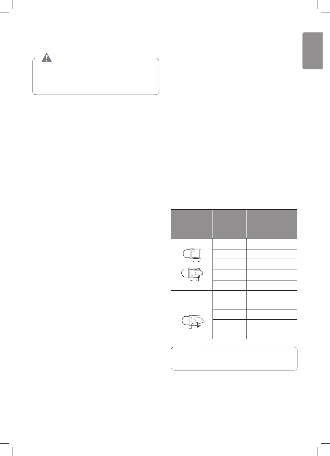
Ductwork
Number
Wall Cap Type
of 90°
Elbows
Recommended
0 65 ft.(19.8 m)
1 55 ft.(16.8 m)
4"
(10.2 cm)
4"
(10.2 cm)
Use only for
short run
installations
2 47 ft.(14.3 m)
3 36 ft.(11.0 m)
4 28 ft.(8.5 m)
0 55 ft.(16.8 m)
1 47 ft.(14.3 m)
2 41 ft.(12.5 m)
21/2"
(6.35 cm)
3 30 ft.(9.1 m)
4 22 ft.(6.7 m)
NOTE
Deduct 6 ft. (1.8 m) for each additional elbow. Do
not use more than four 90° elbows.
Maximum length
of 4-inch (10.2 cm)
diameter rigid metal
duct
22
INSTALLATION
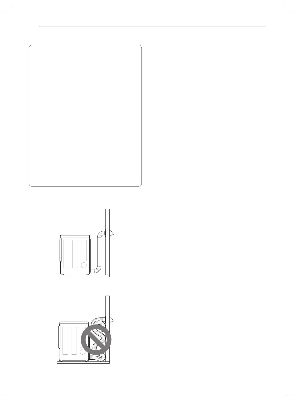
Routing And Connecting Ductwork
NOTE
Follow the guidelines below to maximize drying
performance and reduce lint buildup and
condensation in the ductwork. Ductwork and
fittings are NOT included and must be purchased
separately.
•Use 4-inch (10.2 cm) diameter rigid, semi-rigid
or flexible metal ductwork.
•The exhaust duct run should be as short as
possible.
•Use as few elbow joints as possible.
•The male end of each section of exhaust duct
must point away from the dryer.
•Use duct tape on all duct joints.
•Insulate ductwork that runs through unheated
areas in order to reduce condensation and lint
buildup on duct surfaces.
•Incorrect or inadequate exhaust systems
are not covered by the dryer warranty. Dryer
failures or service required because of such
exhaust systems will not be covered by the
dryer warranty.
Correct Venting
Incorrect Venting
INSTALLATION
ENGLISH
23
Connecting Gas Dryers
WARNING
To reduce the risk of fire or explosion, electric
shock, property damage, injury to persons, or
death when using this appliance, follow basic
safety precautions.
Gas Supply Requirements
As shipped from the factory, this dryer is
•
configured for use with natural gas (NG). It can
be converted for use with propane (LP) gas.
Gas pressure must not exceed 8 inches
(20.3 cm) of water column for NG, or 13 inches
(33 cm) of water column for LP.
A qualified service or gas company technician
•
must connect the dryer to the gas service.
Failure to follow these instructions may result
in fire, explosion, or death.
Isolate the dryer from the gas supply system
•
by closing its individual manual shutoff valve
during any pressure testing of the gas supply.
Failure to do so may result in fire, explosion, or
death.
Supply line requirements: Your laundry room
•
must have a rigid gas supply line to the dryer.
In the United States, an individual manual
shutoff valve MUST be installed within at least
6 ft. (1.8 m) of the dryer, in accordance with
the National Fuel Gas Code ANSI Z223.1 or
Canadian gas installation code CSA B149.1.
A 1/8-inch (0.3 cm) NPT pipe plug must be
installed.
explosion, or death.
If using a rigid pipe, the rigid pipe should be
•
½ inch IPS. If acceptable under local codes and
ordinances and when acceptable to your gas
supplier, 3/8-inch (1 cm) approved tubing may
be used where lengths are less than 20 ft.
(6.1 m). Larger tubing should be used for
lengths in excess of 20 ft. (6.1 m).
so may result in fire, explosion, or death.
Connect the dryer to the type of gas shown on
•
the nameplate.
explosion, or death.
To prevent contamination of the gas valve,
•
purge the gas supply of air and sediment before
connecting the gas supply to the dryer. Before
tightening the connection between the gas
supply and the dryer, purge remaining air until
the odor of gas is detected.
result in fire, explosion, or death.
DO NOT use an open flame to inspect for gas
•
leaks. Use a noncorrosive leak detection fluid.
Failure to do so may result in fire,
Failure to do
Failure to do so may result in fire,
Failure to do so may
Failure to do so may result in fire, explosion, or
death.
Use only a new AGA- or CSA-certified gas
•
supply line with flexible stainless steel
connectors.
explosion, or death.
Securely tighten all gas connections.
•
do so may result in fire, explosion, or death.
Use Teflon tape or a pipe-joint compound
•
that is insoluble in propane (LP) gas on all
pipe threads.
explosion, or death.
DO NOT attempt any disassembly of the dryer;
•
disassembly requires the attention and tools of
an authorized and qualified service technician
or company.
result in fire, explosion, or death.
Failure to do so may result in fire,
Failure to do so may result in fire,
Failure to follow this warning may
Electrical Requirements for Gas
Models Only
Do not, under any circumstances, cut or remove
•
the third (ground) prong from the power cord.
Failure to follow this warning may result in fire,
explosion, or death.
For personal safety, this dryer must be properly
•
grounded.
in fire, explosion, or death.
This dryer must be plugged into a 120-VAC,
•
60-Hz. grounded outlet protected by a
15-ampere fuse or circuit breaker.
this warning may result in fire, explosion, or death.
Where a standard 2-prong wall outlet is
•
encountered, it is your personal responsibility
and obligation to have it replaced with a
properly grounded 3-prong wall outlet.
follow this warning may result in fire, explosion, or
death.
Failure to follow this warning may result
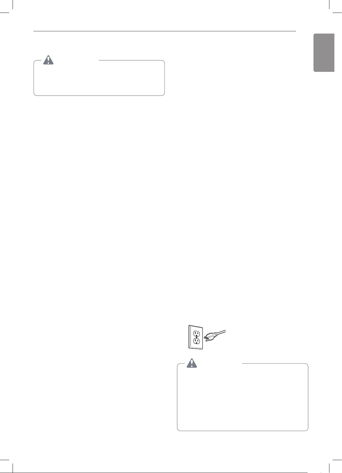
Plug dryer into a 120 VAC,
Plug dryer into a
60 Hz grounded 3-prong
outlet.
WARNING
ELECTRIC SHOCK HAZARD
Failure to follow safety warnings could result in
serious injury or death.
This dryer is equipped with a three-prong
grounding plug for protection against shock
hazard and should be plugged directly into a
properly grounded three-prong receptacle. Do not
cut or remove the grounding prong from this plug.
Failure to
Failure to follow
Failure to
24
INSTALLATION
Connecting the Gas Supply
Installation and service must be performed
•
by a qualified installer, service agency, or the
gas supplier.
explosion, or death.
Use only a new stainless steel flexible
•
connector and a new AGA-certified connector.
Failure to do so may result in fire, explosion, or
death.
A gas shutoff valve must be installed within 6 ft.
•
(1.8 m) of the dryer.
fire, explosion, or death.
The dryer is configured for natural gas when
•
shipped from the factory. Make sure that the
dryer is equipped with the correct burner nozzle
for the type of gas being used (natural gas or
propane gas).
explosion, or death.
If necessary, the correct nozzle (for the LP
•
nozzle kit, order part number 383EEL3002D)
should be installed by a qualified technician
and the change should be noted on the dryer.
Failure to do so may result in fire, explosion, or
death.
All connections must be in accordance with
•
local codes and regulations.
result in fire, explosion, or death.
Gas dryers MUST exhaust to the outdoors.
•
Failure to do so may result in fire, explosion, or
death.
NOTE
This dryer is configured from the factory for
natural gas (NG). If the dryer is to be used with
propane (LP) gas, it must be converted by a
qualified service technician.
Failure to do so may result in fire,
Failure to do so may result in
Failure to do so may result in fire,
Failure to do so may
NOTE
DO NOT use old connectors.
Securely tighten all connections between the
4
dryer and your laundry room’s gas supply.
Turn on your laundry room’s gas supply.
5
Check all pipe connections (both internal and
6
external) for gas leaks with a noncorrosive leakdetection fluid.
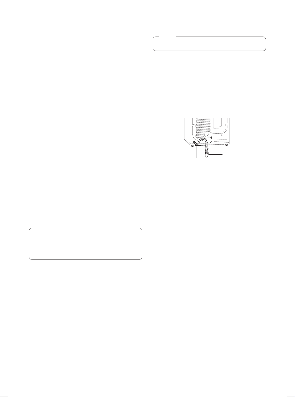
Proceed to Venting the Dryer.
7
3/8"
NPT gas
Connection
AGA/CSA-Certied
Stainless Steel
Flexible Connector
1/8" NPT Pipe Plug
Gas Supply Shutoff
Valve
High-Altitude Installations
The BTU rating of this dryer is AGA-certified for
elevations below 10,000 feet.
If your gas dryer is being installed at an elevation
above 10,000 feet, it must be derated by a qualified
technician or gas supplier.
Make sure that the gas supply to the laundry
1
room is turned OFF and the dryer is unplugged.
Confirm that the type of gas available in your
laundry room is appropriate for the dryer.
Remove the shipping cap from the gas fitting at
2
the back of the dryer. Be careful not to damage
the threads of the gas connector when removing
the shipping cap.
Connect the dryer to your laundry room’s gas
3
supply using a new flexible stainless steel
connector with a 3/8-inch NPT fitting.

INSTALLATION
ENGLISH
25
Connecting Electric Dryers
Electrical Requirements for Electric
Models Only
WARNING
To help prevent fire, electric shock, serious injury,
or death, the wiring and grounding must conform
to the latest edition of the National Electrical
Code, ANSI/NFPA 70 and all applicable local
regulations. Please contact a qualified electrician
to check your home’s wiring and fuses to ensure
that your home has adequate electrical power to
operate the dryer.
This dryer must be connected to a grounded
•
metal, permanent wiring system, or an
equipment-grounding conductor must be run
with the circuit conductors and connected
to the equipment-grounding terminal or lead
on the dryer.
explosion, or death.
The dryer has its own terminal block that must
•
be connected to a separate 240 VAC, 60-Hertz,
single-phase circuit, fused at 30 amperes (the
circuit must be fused on both sides of the
line). ELECTRICAL SERVICE FOR THE DRYER
SHOULD BE OF THE MAXIMUM RATE VOLTAGE
LISTED ON THE NAMEPLATE. DO NOT
CONNECT THE DRYER TO 110-, 115-, OR 120VOLT CIRCUIT.
may result in fire, explosion, or death.
If the branch circuit to dryer is 15 ft. (4.5 m)
•
or less in length, use UL (Underwriters
Laboratories) listed No. 10 AWG wire (copper
wire only), or as required by local codes. If
over 15 ft. (4.5 m), use UL-listed No. 8 AWG
wire (copper wire only), or as required by local
codes. Allow sufficient slack in wiring so the
dryer can be moved from its normal location
when necessary.
fire, explosion, or death.
The power cord (pigtail) connection between
•
the wall receptacle and the dryer terminal block
IS NOT supplied with the dryer. Type of pigtail
and gauge of wire must conform to local codes
and with instructions on the following pages.
Failure to follow these instructions may result in
fire, explosion, or death.
A 4-wire connection is required for all mobile
•
and manufactured home installations, as well
as all new construction after January 1, 1996.
A 4-wire connection must be used where local
codes do not permit grounding through the
neutral wire.
explosion, or death.
•Do not modify the plug and internal wire provided
with the dryer.
•The dryer should be connected to a 4-hole outlet.
•If the plug does not fit the outlet, a proper outlet will
Failure to do so may result in fire,
Failure to follow these instructions
Failure to do so may result in
Failure to do so may result in fire,
need to be installed by a qualified electrician.
Special Electrical Requirements for
Mobile or Manufactured Homes
•Any installation in a manufactured or mobile
home must comply with the Manufactured Home
Construction and Safety Standards Title 24 CFR,
Part 3280 or Standard CAN/ CSA Z240 MH and
local codes and ordinances. If you are uncertain
whether your proposed installation will comply with
these standards, please contact a service and
installation professional for assistance.
A 4-wire connection is required for all mobile
•
and manufactured home installations, as well
as all new construction after January 1, 1996.
Failure to do so may result in fire, explosion, or
death.
•A gas dryer must be permanently attached to the
floor.
•The electrical connection for an electric dryer must
be a 4-wire connection. More detailed information
concerning the electrical connection is provided in
the Connecting Electric Dryers section.
•To reduce the risk of combustion and fire, the dryer
must be vented to the outside.
•DO NOT vent the dryer under a manufactured
home or mobile home.
•Electric dryers may be vented to the outside using
the back, left, right, or bottom panel.
•Gas dryers may be vented to the outside using the
back, left, or bottom panel. Gas dryers may not
be vented to the outside using the right side panel
because of the burner housing.
•The dryer exhaust duct must be affixed securely to
the manufactured or mobile home structure, and
the exhaust duct must be made of a material that
will resist fire and combustion. It is recommended
that you use a rigid, semi-rigid or flexible metal
duct.
•DO NOT connect the dryer exhaust duct to any
other duct, vent, chimney, or other exhaust duct.
•Make sure the dryer has adequate access to
outside fresh air to ensure proper operation. The
opening for outside fresh air must be at least 25 sq.
in (163 cm2).
•It is important that the clearance of the duct from
any combustible construction be at least 2 inches
(5 cm), and when venting the dryer to the outdoors,
the dryer should be installed with a clearance of at
least 1 inch (2.5 cm) at the sides and back of the
dryer.
•Venting materials are not supplied with the dryer.
You must obtain the venting materials necessary
for proper installation.
26
INSTALLATION
WARNING
Connect the power cord to the terminal block.
Connect each wire in the power cord to the
terminal block screw with the matching colored
wire. The terminal block wire colors are indicated
in the manual. Failure to follow these instructions
may result in a short or overload.
Grounding through the neutral conductor is
prohibited for: (1) new branch-circuit installations,
(2) mobile homes, (3) recreational vehicles, and
(4) areas where local codes prohibit grounding
through the neutral conductor.
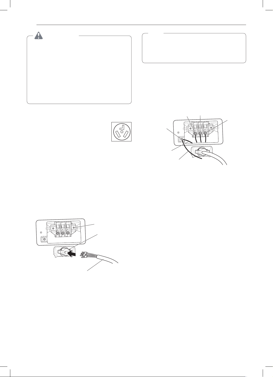
Four-Wire Power Cord
•A 4-wire connection is required for
all mobile and manufactured home
installations, as well as all new
construction after January 1, 1996.
•A UL-listed strain relief is required.
•Use a 30-amp, 240-volt, 4-wire, UL-listed power
cord with #10 AWG-minimum copper conductor and
closed loop or forked terminals with upturned ends.
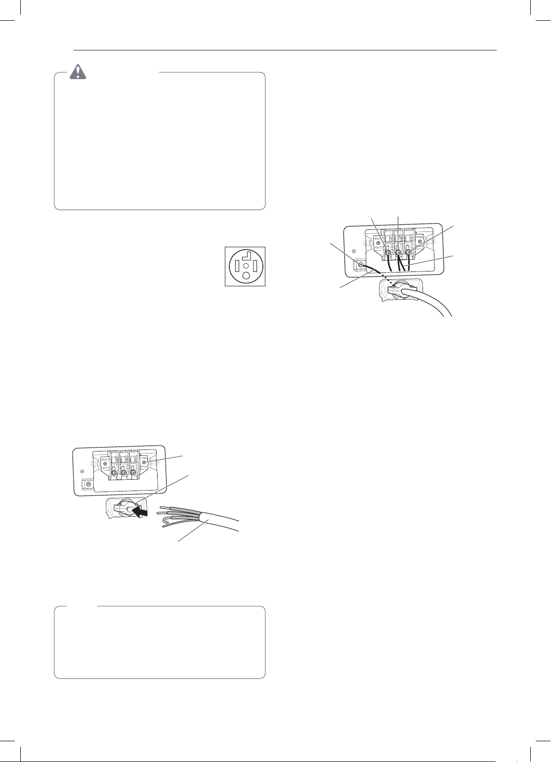
Attach the two hot leads of the power cord to the
5
outer terminal block screws.
Attach the white neutral wire to the center screw
6
of the terminal block.
Attach the power cord ground wire to the green
7
ground screw.
Tighten all screws securely.
8
Reinstall the terminal block access cover.
9
Hot
(Black)
Ground
Screw
Power Cord
Ground Wire
Neutral
(White)
Hot
(Red)
White Wire
moved from
Ground
Screw
Remove the terminal block access cover on the
1
upper back of the dryer.
Install a UL-listed strain relief into the power cord
2
through-hole.
Thread a 30-amp, 240-volt, 4-wire, UL-listed
3
power cord with #10 AWG-minimum copper
conductor through the strain relief.
Terminal Block
UL-Listed
Strain Relief
UL-Listed 4-Wire Power Cord
Transfer the dryer’s ground wire from behind the
4
green ground screw to the center screw of the
terminal block.
NOTE
This dryer is supplied with the neutral wire
grounded. This white ground wire MUST BE
MOVED to the neutral terminal when a 4-wire
cord is to be used, or where grounding through
the neutral conductor is prohibited.
INSTALLATION
ENGLISH
27
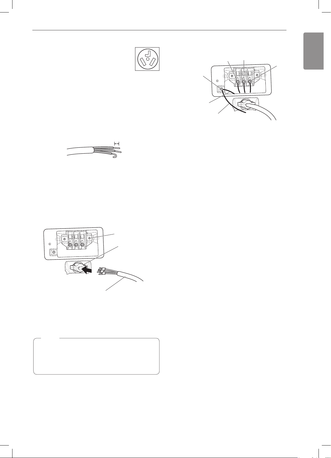
Four-Wire Direct Wire
•A 4-wire connection is required for
all mobile and manufactured home
installations, as well as all new
construction after January 1, 1996.
•A UL-listed strain relief is required.
•Use UL-listed 4-wire #10 AWG-minimum copper
conductor cable. Allow at least 5 ft. (1.5 m) of wire
to allow for removal and reinstallation of the dryer.
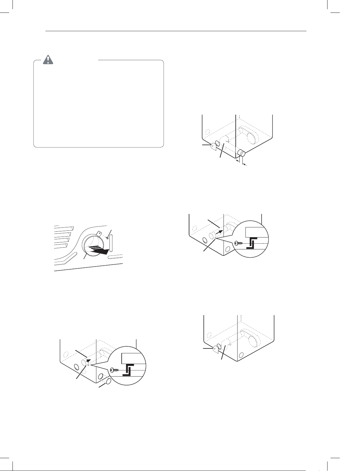
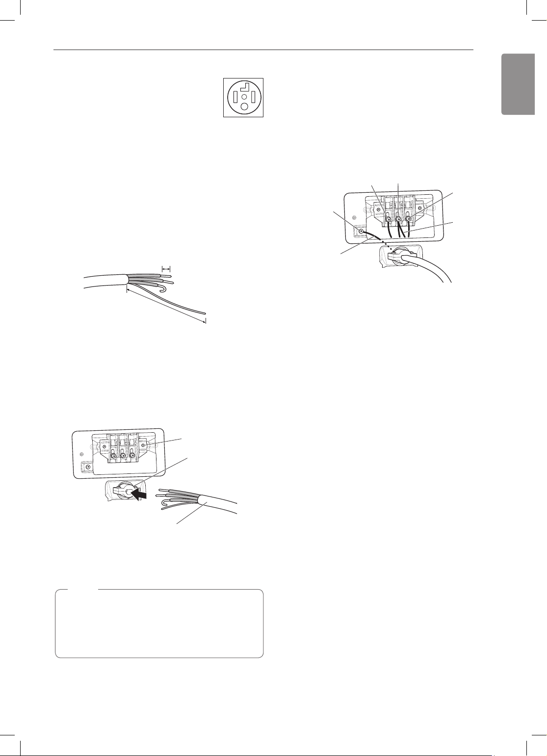
Remove 5 inches (12.7 cm) of the outer covering
1
from the wire. Remove 5 inches (12.7 cm)
of insulation from the ground wire. Cut off
approximately 1½ inches (3.8 cm) from the other
three wires and strip 1 inch (2.5 cm) of insulation
from each wire. Bend the ends of the three
shorter wires into a hook shape.
1" (2.5 cm)
Ground Wire
5"
(12.7 cm)
Remove the terminal block access cover on the
2
upper back of the dryer.
Attach the white neutral wire to the center screw
7
of the terminal block.
Attach the power cord ground wire to the green
8
ground screw.
Tighten all screws securely.
9
Reinstall the terminal block access cover.
10
Hot
(Black)
Ground
Screw
Power Cord
Ground Wire
Neutral
(White)
Hot
(Red)
White Wire
moved from
Ground
Screw
Install a UL-listed strain relief into the power cord
3
through-hole.
Thread the 4-wire #10 AWG-minimum copper
4
power cable prepared in step 1 through the
strain relief.
Terminal Block
UL-Listed
Strain Relief
UL-Listed 4-Wire Power Cord
Transfer the dryer’s ground wire from behind the
5
green ground screw to the center screw of the
terminal block.
NOTE
This dryer is supplied with the neutral wire
grounded. This white ground wire MUST BE
MOVED to the neutral terminal when a 4-wire
cord is to be used, or where grounding through
the neutral conductor is prohibited.
Attach the two hot leads of the power cord to the
6
outer terminal block screws.
28
INSTALLATION
WARNING
Connect the power cord to the terminal block.
Connect each wire in the power cord to the
terminal block screw with the matching colored
wire. The terminal block wire colors are indicated
in the manual. Failure to follow these instructions
may result in a short or overload.
Grounding through the neutral conductor is
prohibited for: (1) new branch-circuit installations,
(2) mobile homes, (3) recreational vehicles, and
(4) areas where local codes prohibit grounding
through the neutral conductor.
Three-Wire Power Cord
•A 3-wire connection is NOT permitted
on new construction after January 1,
1996.
•A UL-listed strain relief is required.
•Use a 30-amp, 240-volt, 3-wire, UL-listed power
cord with #10 AWG-minimum copper conductor and
closed loop or forked terminals with upturned ends.
Remove the terminal block access cover on the
1
upper back of the dryer.
NOTE
The dryer is supplied with the neutral conductor
grounded. If a 3-wire cord is to be used and is
allowed, make sure the white neutral grounding
wire is connected to the green ground screw.
Connect the external ground (if required by local
6
codes) to the green ground screw.
Tighten all screws securely.
7
Reinstall the terminal block access cover.
8
Neutral
(White)
Hot
(Red)
Ground
Screw
White Wire
from Dryer
harness
Hot
(Black)
External Ground
Wire (If required
by local codes)
Install a UL-listed strain relief into the power cord
2
through-hole.
Thread a 30-amp, 240-volt, 3-wire, UL-listed
3
power cord with #10 AWG-minimum copper
conductor through the strain relief.
Terminal Block
UL-Listed
Strain Relief
UL-Listed 3-Wire Power Cord
Attach the two hot leads (black and red) of the
4
power cord to the outer terminal block screws.
Attach the neutral (white) wire to the center
5
terminal block screw.
INSTALLATION
ENGLISH
29
Three-Wire Direct Wire
•A 3-wire connection is NOT permitted
on new construction after January 1,
1996.
•A UL-listed strain relief is required.
•Use UL-listed 3-wire, #10 AWG-minimum copper
conductor cable. Allow at least 5 ft. (1.5 m) length
to allow for removal and installation of dryer.
Remove 3½-inch (8.9 cm) of the outer covering
1
from the wire. Strip 1 inch (2.5 cm) insulation
from each wire. Bend the ends of the three wires
into a hook shape.
1" (2.5 cm)
Remove the terminal block access cover on the
2
upper back of the dryer.
Install a UL-listed strain relief into the power cord
3
through-hole.
Thread the 3-wire, #10 AWG-minimum copper
4
conductor power cable prepared in step 1
through the strain relief.
Terminal
Block
UL-Listed
Strain Relief
Reinstall the terminal block access cover.
9
Ground
Screw
White Wire
from Dryer
harness
Hot
(Black)
External Ground
Wire (If required by
local codes)
Neutral
(White)
Hot
(Red)
Final Installation Check
Once you have completed the installation of the dryer
and it is in its final location, confirm proper operation
with the following tests and the Installation Test (Duct
Check) on the following page.
Testing Dryer Heating
GAS MODELS
Close the dryer door, press the
the dryer on, and start the dryer on a heat setting.
When the dryer starts, the igniter should ignite the
main burner.
ELECTRIC MODELS
Close the dryer door, press the
the dryer on, and start the dryer on a heat setting.
The exhaust air should be warm after the dryer has
been operating for 3 minutes.
POWER
POWER
button to turn
button to turn
UL-Listed 3-Wire Power Cord
Attach the two hot leads (black and red) of the
5
power cord to the outer terminal block screws.
Attach the neutral (white) wire to the center
6
terminal block screw.
NOTE
The dryer is supplied with the neutral conductor
grounded. If a 3-wire cord is to be used and is
allowed, make sure the white neutral grounding
wire is connected to the green ground screw.
Connect the external ground (if required by local
7
codes) to the green ground screw.
Tighten all screws securely.
8
Checking Airow
Effective dryer operation requires proper airflow.
The adequacy of the airflow can be measured by
evaluating the static pressure. Static pressure in the
exhaust duct can be measured with a manometer,
placed on the exhaust duct approximately 2 ft. (60.9
cm) from the dryer. Static pressure in the exhaust duct
should not exceed 0.6-inch (1.5 cm). The dryer should
be checked while the dryer is running with no load.
Checking Levelness
Once the dryer is in its final location, recheck the
dryer to be sure it is level. Make sure it is level front
to back and side to side, and that all four leveling feet
are firmly on the floor.
Checking Venting
Vent ductwork should be checked for lint buildup
and cleaned at least once per year. If any noticeable
reduction in drying performance occurs, check duct
for obstructions and blockages.
30
INSTALLATION
Installation Test (Duct Check)
Once you have completed the installation of the
dryer, use this test to make sure the condition of the
exhaust system is adequate for proper operation of
the dryer. This test should be performed to alert you
to any serious problems in the exhaust system of
your home.
•This dryer features Flow Sense™, an innovative
sensing system that automatically detects
blockages and restrictions in dryer ductwork.
Keeping ductwork clean of lint buildup and free of
restrictions allows clothes to dry faster and reduces
energy use.
NOTE
The dryer should be cool before starting this test.
If the dryer was warmed up during installation, run
the AIR DRY cycle for a few minutes to reduce
the interior temperature.
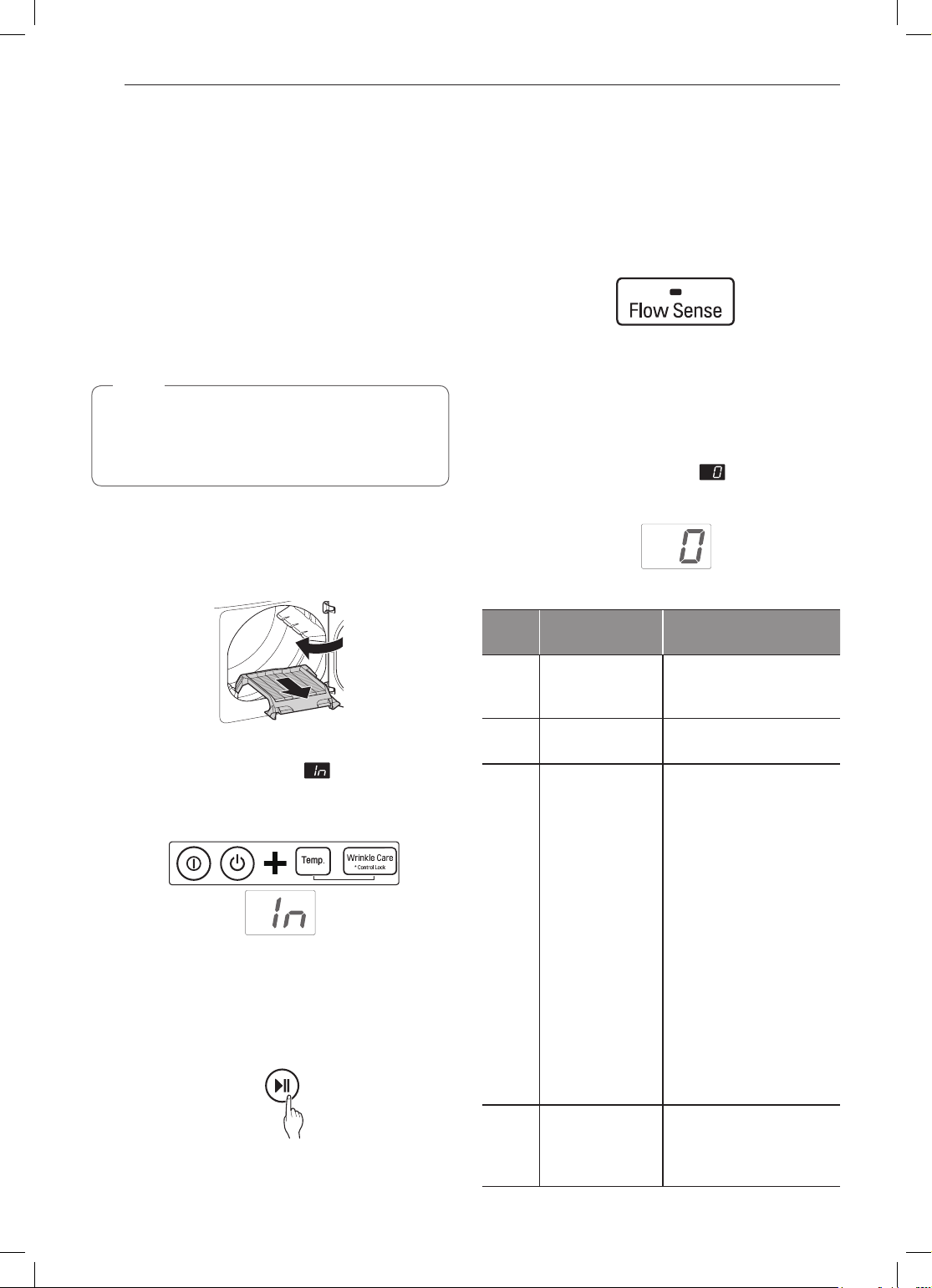
To activate the installation test:
Remove the drying rack and literature, and
1
then close the door.
Do not load anything in the drum for this test, as
in may affect the accuracy of the results.
Check the display for results.
4
During the test cycle, monitor the Flow Sense™
display on the control panel. If the Flow Sense™
LED is not turned on, when the cycle ends,
the exhaust system is adequate. If the exhaust
system is severely restricted, the Flow Sense™
LED will be turned on. Other problems may also
be shown with error codes. See the chart below
for error code details and solutions.
LED; turned on :
RESTRICTED
The Flow Sense™ LED indicates that the exhaust
system is severely restricted. Have the system
checked immediately, as performance will be poor.
End of cycle.
5
At the end of the test cycle, will display.
The test cycle will end and the dryer will shut off
automatically after a short delay.
Check the error code before you call for service
•
Press and hold the
2
Wrinkle Care
count alternate in the display. (The usage count
indicates the number of cycles run with no load
during the last 5 cycles.)
Press the START/PAUSE button.
3
The dryer will start the test, which will last about
2 minutes. The heat will be turned on and the
temperatures in the drum will be measured and
displayed. A chime sounds when the test portion
of the cycle is complete.
POWER, Temp., and
buttons until and a usage
Error
Code
tE1
or
tE2
HS
PS
or PF
or nP
gAS
Possible
Causes
•Temperature
sensor
failure.
•Humidity
sensor failure.
•Electric
dryer power
cord is not
connected
correctly, or
house power
supply is
incorrect.
•House fuse is
blown, circuit
breaker
has tripped,
or power
outage has
occurred.
•Gas supply or
service turned
off. (Gas
Model only.)
Solutions
•Turn off the dryer and
call for service.
•Turn off the dryer and
call for service.
•Check the power
supply or the
connection of the
power cord to the
terminal block. Refer
Connecting
to the
Electric Dryers
section of this
manual for complete
instructions.
•Reset circuit breaker
or replace fuse. Do
not increase the
fuse capacity. If the
problem is a circuit
overload, have
it corrected by a
qualified electrician.
•Confirm that house
gas shutoff and the
dryer gas shutoff are
both fully open.
Check the duct condition
•
 Loading...