

LG DLG3788 Service Manual
29
Disassemble and repair the unit only after pulling out power plug from the outlet.
DISASSEMBLY INSTRUCTIONS
11
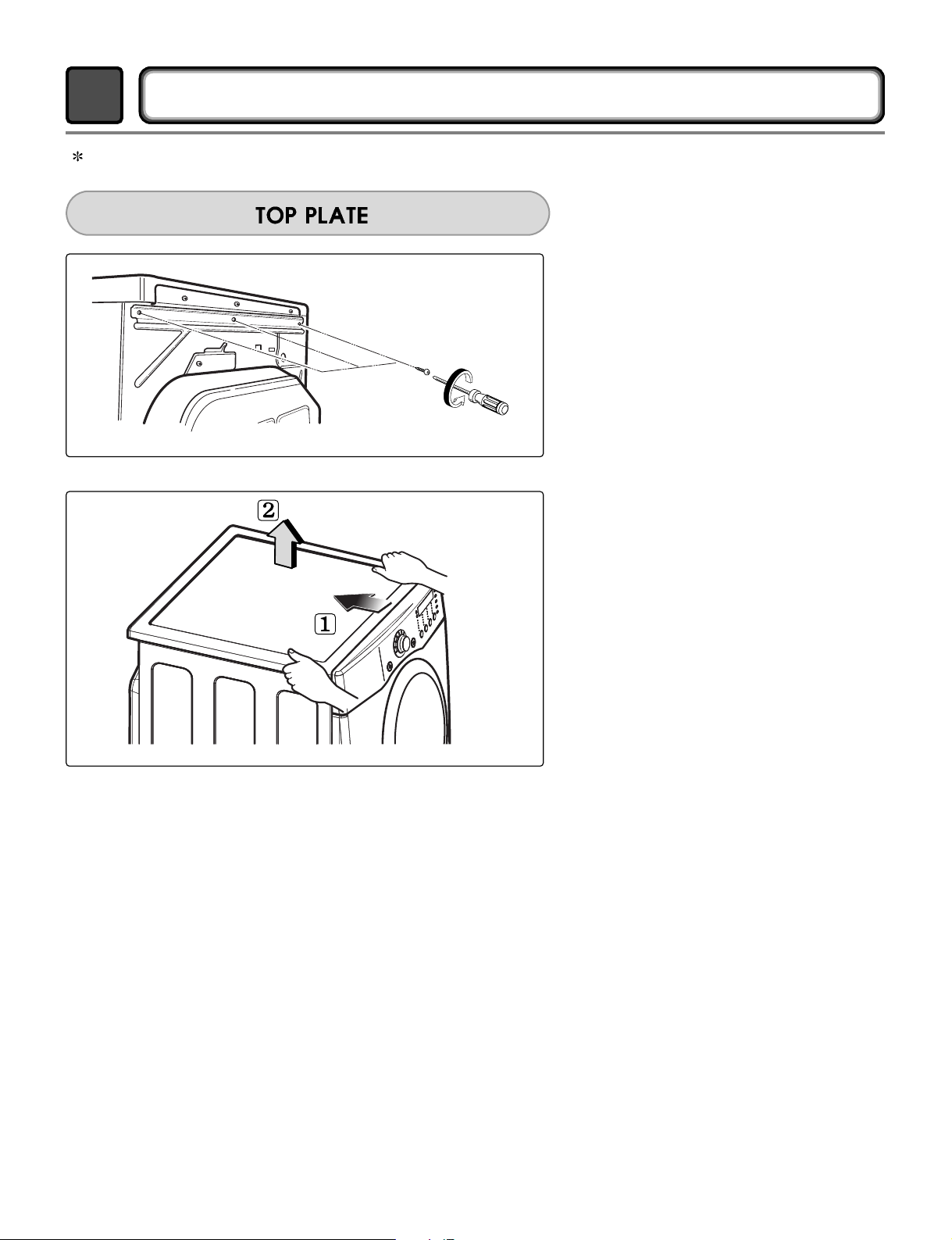
1.
Remove 3 screws on the plate upper.
2.
Push the top plate
3.
Open the top plate
30
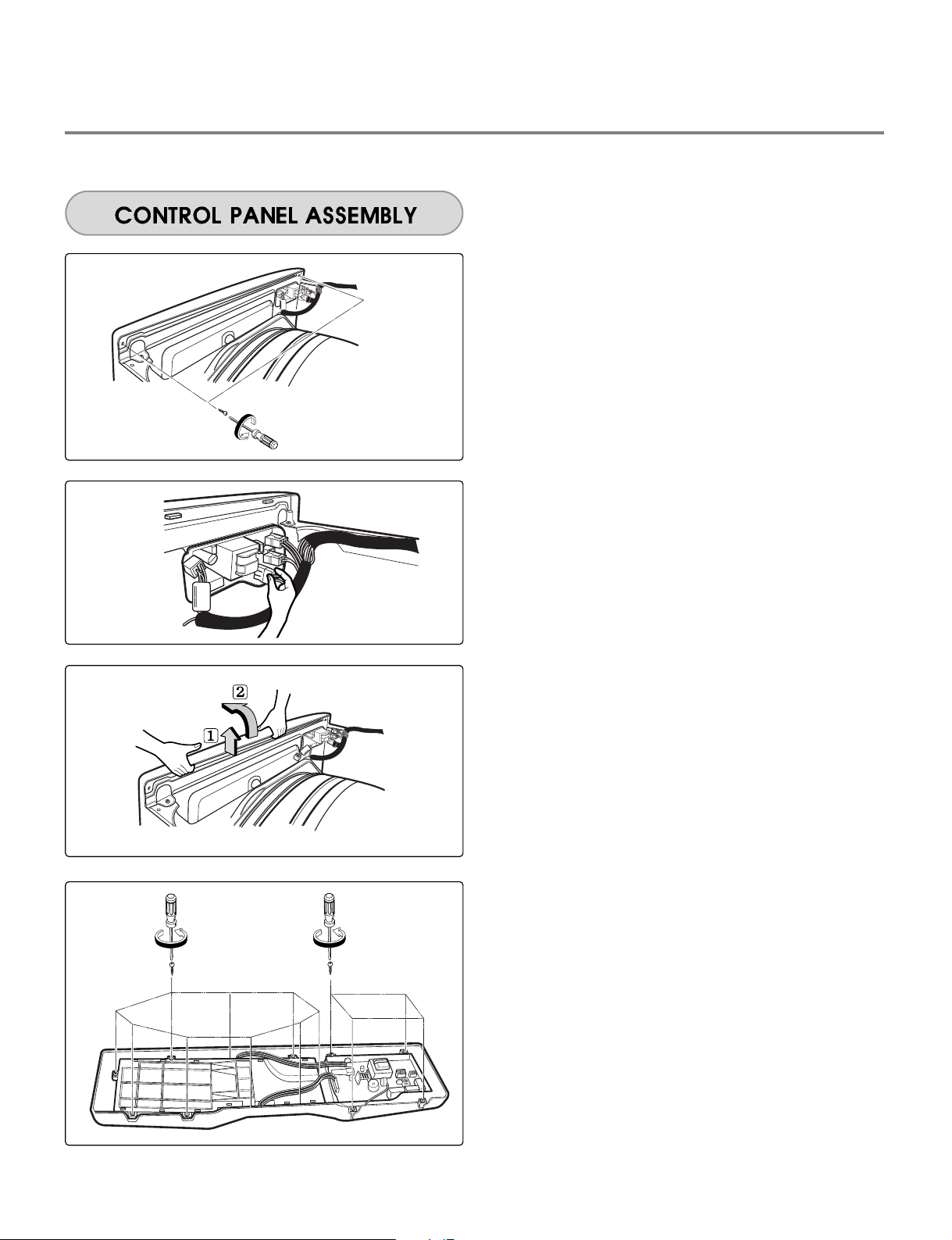
1.
Remove 2 screw on the control panel frame.
2.
Disconnect the connectors.
3.
Pull the control panel assembly.
4.
Remove 9 screws on the PWB(PCB)
assembly, display.
5.
Remove 4 screws on the PWB(PCB)
assembly, main.
6.
Disassemble the control panel assembly.
31
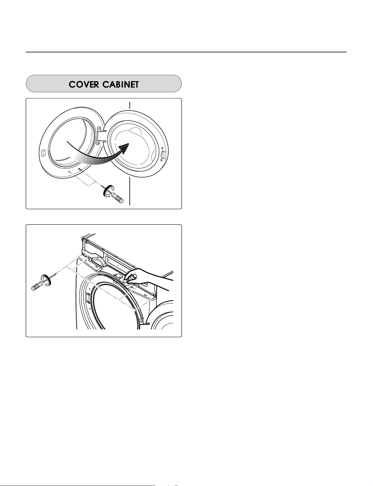
1.
Open the top plate.
2.
Open the control panel assembly.
3.
Open the door assembly.
4.
Remove 2 screws.
5.
Remove 4 screws from upper side.
6.
Disconnect the harness of door switch.
 Loading...