

LG DLE5932W Owner's Manual
DLE5911W
DLE2511W
DLE5932W
DLE5932S
DLE2532W
DLG5911W
Owner's Manual
ElectricandGasDryer
Thankyou for buying an LGdryer.
DLG2511W
DLG5932W
Pleasereadyour owner's manual carefully,as it provides
instructionson safeinstallation, use,and maintenance.
Retainit for future referenceand record themodel and serial
of your dryer.
PROPIETARIO
El_ctricay Gas
Autom6tica LG.
_ietariocuidadosamente,ya que
la segurainstalaci6n,manejo
futurasreferencias,archive
susecadora.
:TAB OF CONTENTS
SAFETY INSTRUCTIONS .............................................................................................................................................. 2-5
BEFORE USING YOUR NEW DRYER ......................................................................................................................... 2
IMPORTANT SAFETY INSTRUCTIONS ...................................................................................................................... 3
LG DRYER WARRANTY ............................................................................................................................................ 5
INSTALLATION INSTRUCTIONS ................................................................................................................................ 6-21
INSTALLING THE DRYER .......................................................................................................................................... 7
DOOR REVERSAL PROCEDURE ............................................................................................................................ 10
MANUFACTURED (MOBILE) HOME INSTALLATION ............................................................................................... 11
ELECTRICAL REQUIREMENTS - ELECTRICAL DRYER ........................................................................................ 12
ELECTRICAL REQUIREMENTS - GAS DRYER ........................................................................................................ 16
GAS REQUIREMENT .......................................................................................................................................... 18
EXHAUST REQUIREMENTS ..................................................................................................................................... 19
OPERATION INSTRUCTIONS ................................................................................................................................... 22-28
USER • MAIN * TENANCE ......................................................................................................................................... 22
FEATURES AND BENEFITS ...................................................................................................................................... 23
TROUBLESHOOTING TIPS ...................................................................................................................................... 29-30
BEFORE YOU CALL FOR SERVICE ......................................................................................................................... 28
CUSTOMER SERVICE ............................................................................................................................................... 30-31
SERVICE TELEPHONE NUMBER ............................................................................................................................. 30
LG DRYER LIMITED WARRANTY ............................................................................................................................. 31
Please read this manual. It will help you install and operate
your new LG dryer in the safest and most economical way.
If you need more information about the care and operation of
LG appliances, call your nearest LG store. You will need
the complete model and serial numbers when requesting
information.
Your dryer's model and serial numbers are located on the
Model and Serial Number Plate located on the front of the
dryer behind the door.
LG SERVICE Call : 1-877-714-7483
Use the space below to record the model number
and serial number of your new LG dryer.
Model No.
Serial No.
Date of Purchase
2
READALLINSTRUCTIONSBEFOREUSING.
WARNING!
For your safely, the recommendations in this manual must be followed.. Toreduce the
risk of fire or explosion, electric shock, or to prevent property damage, personal injury,
or death when using your appliance, follow basic precautions, including the following.
• Do not store or use gasoline or other • Installation and service must be
flammable vapors and liquids in the performed by a qualified installer or
vicinity of this or any other service agency.
appliance.
WHAT TO DO IF YOU SMELL GAS:
• Do not try to light a match, or cigarette,
or turn on any gas or electrical
appliance.
• Do not touch any electrical switches.
Do not use any phone in your building.
• Clear the room, building or area of all
occupants.
California Safe Drinking Water and Toxic Enforcement Act
This act requires the governor of California to publish a list of substances known to the state to cause cancer, birth
defects or other reproductive harm and requires businesses to warn customers of potential exposure to such substances.
Gas appliances can cause minor exposure to four of these substrances, namely benzene, carbon monoxide, formaldehyde
and soot, caused primarily by the incomplete combustion of natural gas or LP fuels.
Properly adjusted dryers will minimize combustion. Exposure to these substances can be minimized further by properly
venting the dryer to the outdoors.
• Immediately call your gas supplier
from a neighbor's phone. Follow the
gas supplier's instructions carefully.
• ffyou cannot reach your gas supplier,
call the fire department.
3
tL
IMPORTANT SAFETY INSTRUCTIONS
WARNING - To reduce the risk of fire, electric shock, or
injury to persons when using your appliance, follow basic
precautions, including the following:
1) Read all instructions before using the appliance.
2) Do not dry articles that have come into contact with
gasoline, dry-cleaning solvents, or other flammable or
explosive substances, as they give off vapors that could
ignite or explode.
3) Do not allow children to play on or in the appliance. Close
supervision of children is necessary when using the
appliance.
4) Before the appliance is removed from service or
discarded, remove the door to the drying compartment.
5) Do not reach into the appliance if the drum is moving.
6) Do not install or store this appliance where it will be
exposed to the weather.
7) Do not tamper with controls.
SAVE THESE INSTRUCTIONS
For a grounded, cord-connected appliance:
GROUNDING INSTRUCTIONS
This appliance must be grounded. In the event of
malfunction or breakdown, grounding will reduce the risk of
electric shock by providing a path of least resistance for
electric current. This appliance is equipped with a cord
having an equipment-grounding conductor and a grounding
plug. The plug must be plugged into an appropriate outlet
that is properly installed and grounded in accordance with all
local cedes and ordinances.
WARNING - Improper connection of the equipment-
grounding conductor can result in a risk of electric shock.
Check with a qualified electrician or service person if you
are in doubt as to whether the appliance is properly
grounded.
8) Do not repair or replace any part of the appliance or
attempt any servicing unless specifically recommended in
the user-maintenance instructions.
9) Do not use heat to dry articles containing foam rubber or
similarly textured rubber-like materials.
10) Clean lint screen before or after each load.
11) Keep area around the exhaust opening and adjacent
surrounding areas free from the accumulation of lint,
dust, and dirt.
12) The interior of the appliance and exhaust duct should be
cleaned periodically by qualified service personnel.
13) Do not place items exposed to cooking oils in your dryer.
Items contaminated with cooking oils may contribute to
a chemical reaction that could cause a load to catch fire.
14) Do not use fabric sofrners or products to eliminate static
unless recommended by the manufacturer of the fabric
softner or product.
Do not modify the plug provided with the appliance: if it will
not fit the outlet, have a proper outlet installed by a qualified
electrician.
For a permanently connected appliance:
GROUNDING INSTRUCTIONS
This appliance must be connected to a grounded metal
permanent wiring system. Alternatively, an equipment-
grounding conductor must be run with the circuit conductors
and connected to the equipment-grounding terminal or lead
on the appliance.
4
FullOne Year Warranty on Mechanical and Electrical
Parts
For one year from the date of purchase, if this dryer is
installed and operated according to the instructions in
this manual, LG will repair or replace any of its
mechanical or electrical parts if they are defective in
material or workmanship.
NOTE : Exhausting your dryer with a plastic vent may
void this warranty. Refer to section on Dryer Exhaust
Requirements.
Warranty Restriction
If the dryer is subjected to other than private family
LG& You,A ServicePartnership.
IMPORTANT!
Staplesalesslipor cancelledcheckhere.
Proof of the original purchase date is needed to obtain service under the warranty.
use, all warranty coverage is effective for only 90
days.
Warranty Service
Warranty service is available by contacting your
nearest LG Service Center in the United States.
www.LGESERVlCE.COM
This waranty applies only while this dryer is in use in
the United States.
This warranty gives you specific legal rights, and you
may also have other rights which vary from state to
state.
FOR YOURRECORDS
Write the model and serial numbers here:
#
#
They are on the label on the front of the dryer behind the door.
READTHISMANUAL
Inside you will find many helpful hints on how to use and maintain your dryer properly. Just a little
preventive care on your part can save you a great deal of time and money over the life of your dryer.
PROPERVENTING
For the best drying performance the dryer needs to be properly vented. The dryer will use more energy and
take longer to dry if it is not venW_.dto the specifications outlined in the Venting the Dryer section in this
manual and the Exhausting section in the Installation Instructions.
IF YOU NEED SERVICE
You'll find many answers to common problems in the Troubleshooting Tips section. If you review our
chart of Troubleshooting Tips first, you may not need to call for service.
If you do need service, you can relax knowing help is only a phone call away. A list of toll-free customer
service numbers is included in the back section. In the U.S., you can always call the LG Answer Center.
(SERVICE Call No. 1-877-714-7483)
5

i" "S TALLATIONINSTRUCTIONS
Installation clearances
The location must be large enough to fully open the
dryer door.
Dryer Dimensions
. 43"
(109.22 cm)
* Most installations require a minimum 5'/2 in.
(14 cm) clearance behind the dryer for the
exhaust vent with elbow.
Minimum installation spacing for a recessed
area, customized undercounter or closet
installation
Closet installation - Dryer only
3"--[ --_ _'t
48._j (
(310 cm _)
24 "_ (_ i_)t
'/
(155cm')x_ ,1
(7.6crn)
'_ 14"max
_ ,o,r_F"--
(45.72 era)
F+
i !i
J I" _31.5"_[1;
(2.54cm) (80.01cm) (2.54cm)
The following dimensions shown are for the
minimum spacing allowed.
• Additional spacing should be considered for
installation and servicing.
• Additional clearances might be required for wall,
door and floor moldings.
• Additional spacing of 1in. (2.5 cm) on all sides of
the dryer is recommended to reduce noise
transfer.
• For closet installation with a door, minimum
ventilation openings in the top and bottom of the
door are required. Louvered doors with
equivalent ventilation openings are acceptable.
Companion appliance spacing should also be
considered.
o"-_l_ 27"_}-_-o"
(Ocm) (68.6 cm) (0cm)
6
Step 1 : Position and Level the Dryer
For further assistance refer to section on Location
Requirements.
• DO NOT use plastic or thin foil ducting.
• Locate dryer so exhaust duct is as short as
possible.
Place the dryer in position, and adjust the legs until the
dryer is level from side to side and front to back.
Level floor : Maximum slope under entire dryer should
not be more than 2.5cm (l inch). If slope is greater than
2.5 cm (linch), clothes may not tumble properly and
automatic sensor cycles may not operate correctly if
dryer is not leveI.
Step 2 : Connect Dryer Exhaust System
For further assistance refer to sections on Location
Requirements and Dryer Exhaust Requirements.
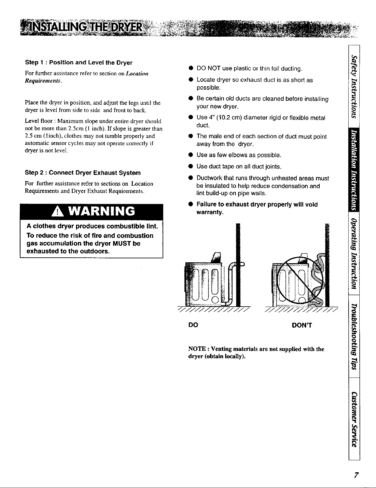
T!II&'L'lfl
A clothes dryer produces combustible lint.
To reduce the risk of fire and combustion
gas accumulation the dryer MUST be
exhausted to the outdoors.
• Be certain old ducts are cleaned before installing
your new dryer.
• Use 4" (10.2 cm) diameter rigid or flexible metal
duct.
• The male end of each section of duct must point
away from the dryer.
• Use as few elbows as possible.
• Use duct tape on all duct joints.
• Ductwork that runs through unheated areas must
be insulated to help reduce condensation and
lint build-up on pipe walls.
• Failure to exhaust dryer properly will void
warranty.
///////////////
DO
NOTE : Venting materials are not supplied with the
dryer (obtain locally).
///////////////
DON'T
7
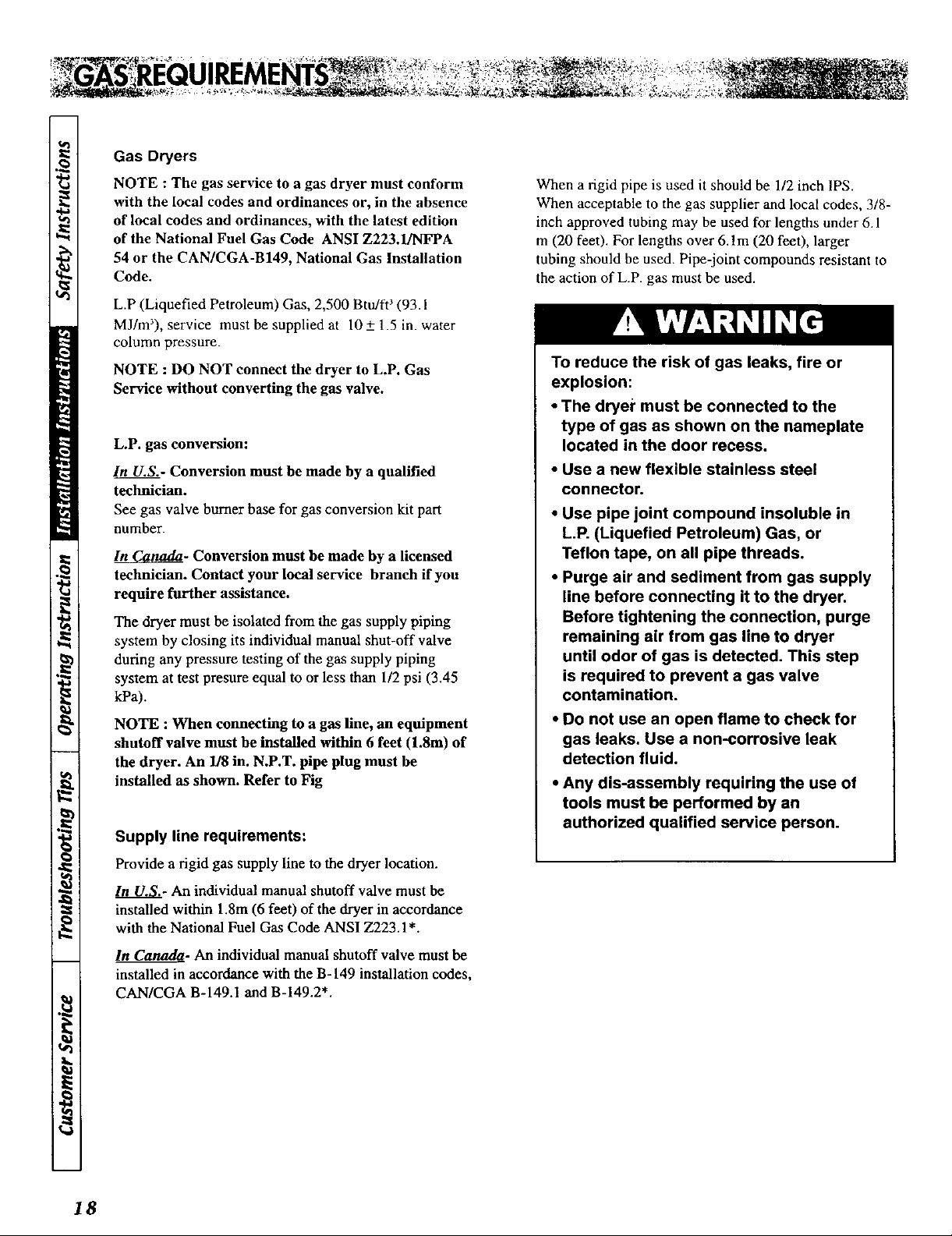
Step 3 : Connect Gas Supply Pipe
(Gas Dryer ONLY)
For further assistance, refer to section on Gas
Requirements.
1. Make certain your dryer is equipped for use with the
type of gas in your laundry room. Dryer is equipped at
the factory for Natural Gas with a 3/8" N.P.T. gas
connection.
2. Remove the shipping cap from the gas connection at
the rear of the dryer. Make sure you do not damage the
pipe thread when removing the cap.
3. Connect to gas supply pipe using a new flexible
stainless steel connector.
4. Tighten all connections securely. Turn on gas and
check all pipe connections (internal & external) for
gas leaks with a non-corrosive leak detection fluid.
5. For L.P. (Liquefied Petroleum) gas connection, refer
to section on Gas Requirements.
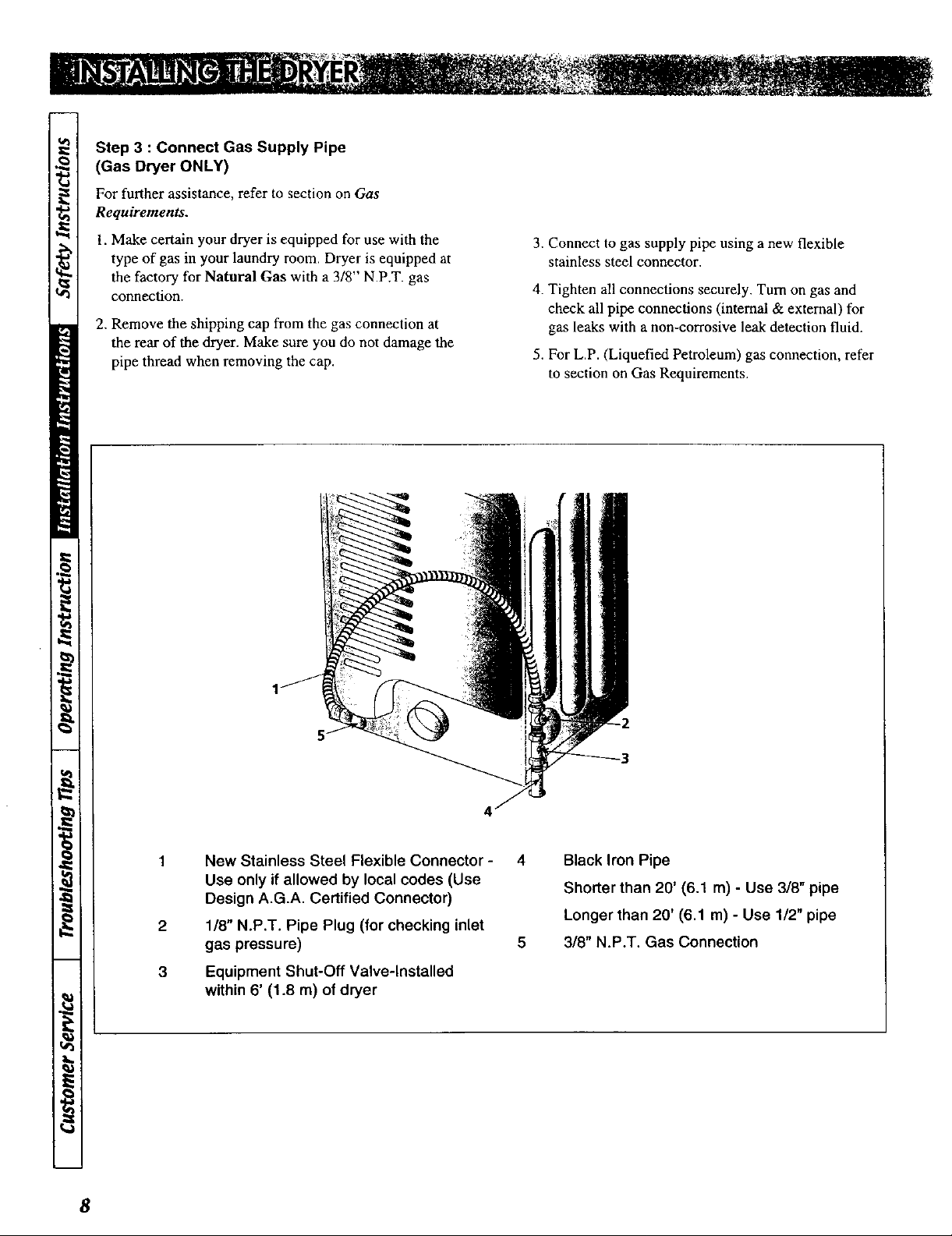
New Stainless Steel Flexible Connector - 4
Use only if allowed by local codes (Use
Design A.G.A. Certified Connector)
2
1/8" N.P.T. Pipe Plug (for checking inlet
gas pressure) 5
3
Equipment Shut-Off Valve-Installed
Black Iron Pipe
Shorter than 20' (6.1 m) - Use 3/8" pipe
Longer than 20' (6.1 m) - Use 1/2" pipe
3/8" N.P.T. Gas Connection
within 6' (1.8 m) of dryer
8
Step 4: (Electric Dryer Only) Connect
Electrical Plug
For further assistance refer to section on Electrical
Requirements.
IMPORTANT : Use only a new U.L. listed No. 10
(copper wire only) three conductor power supply
cord kit rated 240 Volts (minimum)30 Amperes
and labeled as suitable for use in a clothes dryer.
NOTE : For more detailed information on
connection three-wire or four-wire plugs, refer to
section on Electric Dryer Electrical Requirements.
NOTE : Four-wire cord is required for mobile
homes or where codes do not permit grounding
through neutral.
Step 5: Wipe Out Inside of Dryer
Before using dryer for the first time, use an all-purpose
cleaner, or a detergent and water solution, and a damp
cloth to remove shipping dust from inside the dryer
drum.
Heat Source Check
Electric Dryers
Close the loading door and start the dryer in a heat
setting (refer to the Operating Instructions supplied with
the dryer). After the dryer has operated for three minutes,
the exhaust air or exhaust pipe should be warm.
Gas Dryers
Close the loading door, start the dryer in a heat setting
(refer to the Operating Instructions supplied with the
dryer); the dryer will start, the igniter will glow red and
the main burner will ignite.
IMPORTANT : If all air is not purged out of the gas
line, the gas igniter may go off before gas it is ignited.
If this happens, after approximately two minutes the
igniter will again attempt gas ignition.
Step 6: Plug In the Dryer
Refer to section on Electrical Requirements, and
connect the dryer to an electrical power source.
Step 7: Check Installation
9
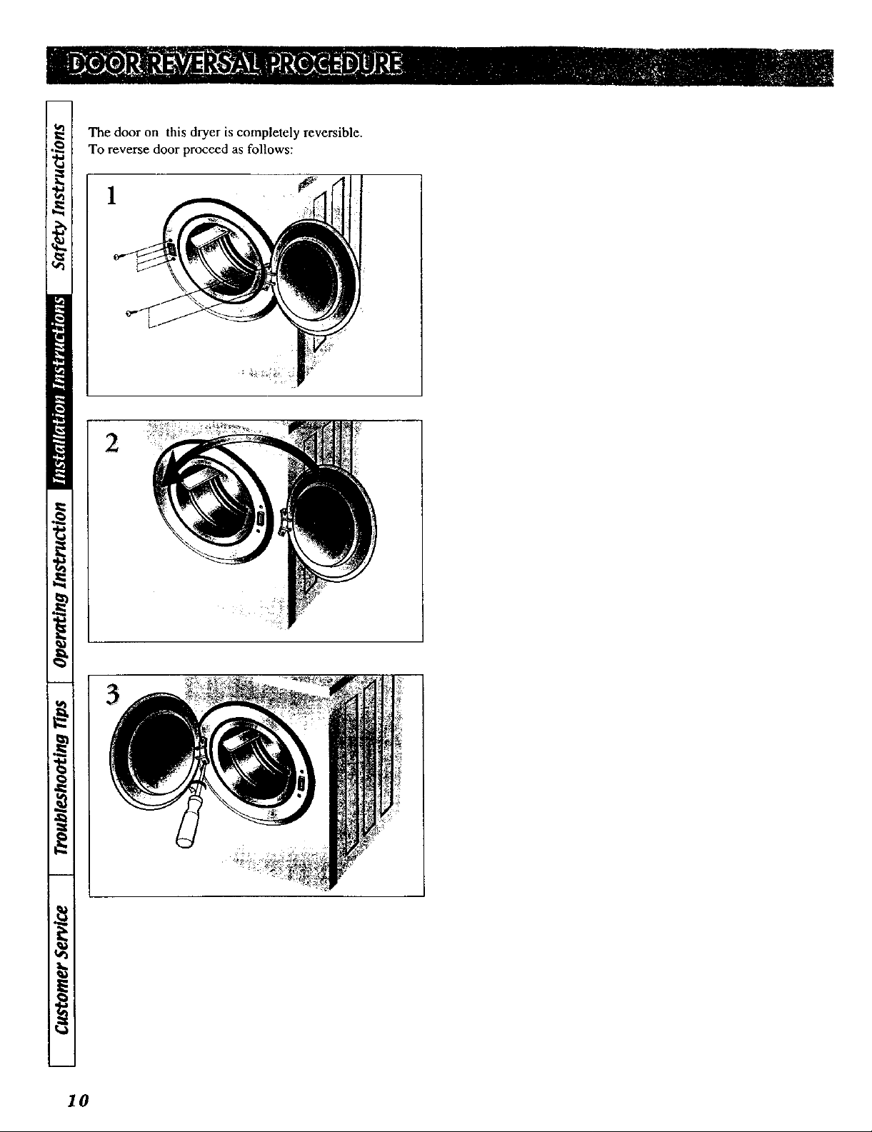
The door on this dryer is completely reversible.
To reverse door proceed as follows:
1
I0
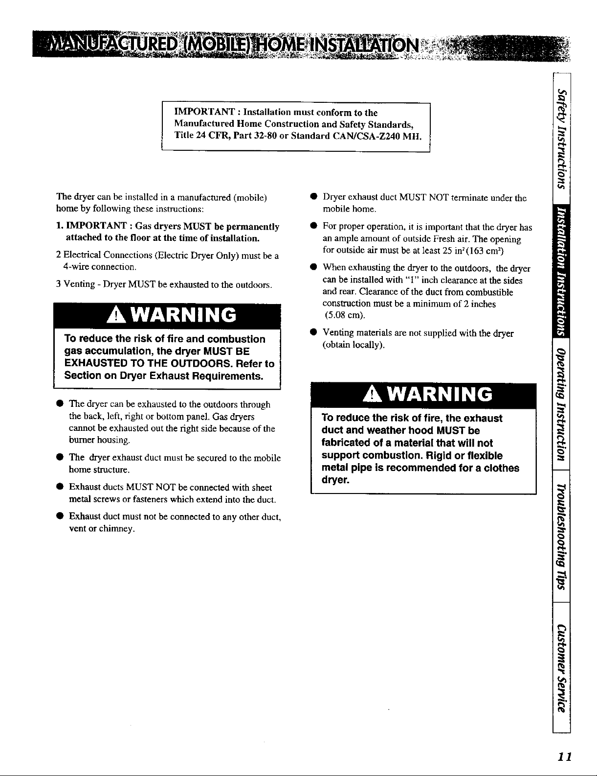
IMPORTANT : Installation must conform to the
Manufactured Home Construction and Safety Standards,
Title 24 CFR, Part 32-80 or Standard CAN/CSA-Z240 MH.
The dryer can be installed in a manufactured (mobile)
home by following these instructions:
1. IMPORTANT : Gas dryers MUST be permanently
attached to the floor at the time of installation.
2 Electrical Connections (Electric Dryer Only) must be a
4-wire connection.
3 Venting - Dryer MUST be exhausted to the outdoors.
To reduce the risk of fire and combustion
gas accumulation, the dryer MUST BE
EXHAUSTED TO THE OUTDOORS. Refer to
Section on Dryer Exhaust Requirements.
• The dryer can be exhausted to the outdoors through
the back, left, right or bottom panel. Gas dryers
cannot be exhausted out the right side because of the
burner housing.
• The dryer exhaust duct must be secured to the mobile
home structure.
• Exhaust ducts MUST NOT be connected with sheet
metal screws or fasteners which extend into the duct.
• Dryer exhaust duct MUST NOT terminate under the
mobile home.
• For proper operation, it is important that the dryer has
an ample amount of outside Fresh air. The opening
for outside air must be at least 25 in2(163 cm2)
• When exhausting the dryer to the outdoors, the dryer
can be installed with "'1" inch clearance at the sides
and rear. Clearance of the duct from combustible
construction must be a minimum of 2 inches
(5.08 cm).
• Venting materials are not supplied with the dryer
(obtain locally).
To reduce the risk of fire, the exhaust
duct and weather hood MUST be
fabricated of a material that will not
support combustion. Rigid or flexible
metal pipe is recommended for a clothes
dryer.
• Exhaust duct must not be connected to any other duct,
vent or chimney.
11

Electric Dryers
(120V/240 Volt, 60 Hertz, 3-Wire Installation)
(120V/208 Volt, 60 Hertz, 3-Wire Installation)
NOTE : The wiring diagram is located inside the
control hood.
To reducd the risk of fire, electric shock,
serious injury or death, all wiring and
grounding MUST conform with the latest
edition of the National Electrical Code,
ANSI/NFPA 70, or the Canadian Electrical
Code, CSA C22.1, and such local
regulations as might apply. It is the
customer's responsibility to have the
wiring and fuses checked by a qualified
electrician to make sure your home has
adequate electrical power to operate the
dryer.
Grounding Instructions
• This dryermust beconnectedto a groundedmetal,
permanent wiring system; or an equipment-grounding
conductor must be run with the circuit conductors and
connected to the equipment-grounding terminal or
lead on the dryer.
The dryer has its own terminal block that must be
connected to a separate branch, 60 Hertz, single phase
circuit, AC (alternating current) circuit, fused at 30
Amperes (the circuit must be fused on both sides of
the line). ELECTRICAL SERVICE FOR THE
DRYER SHOULD BE OF MAXIMUM RATE
VOLTAGE LISTED ON THE NAMEPLATE. DO
NOT CONNECT DRYER TO 110, I15, OR 120
VOLT CIRCUIT. Heating elements are available for
field installation in dryers which are to be conected to
electrical service of different voltage than that listed
on nameplate, such as 208 Volt.
• If branch circuit to dryer is fifteen feet (4.50 m) or
less in length, use U.L. (Underwriters Laboratories)
listed No. 10 A.W.G. wire (copper wire only), or as
required by local codes. If over fifteen feet (4.50 m),
use U.L (Underwriters Laboratories) listed No. 8
A.W.G. wire (copper wire only), or as required by
local codes. Allow sufficient slack in wiring so dryer
can be moved from its normal location when
necessary.
• The power cord (pigtail) connection between wall
receptacle and dryer terminal block IS NOT supplied
with dryer. Type of pigtail and gauge of wire must
conform to local codes and with instructions
mentioned on the following pages.
• The method of wiring the dryer is optional and
subject to local code requirements. Refer to examples
on next page.
12
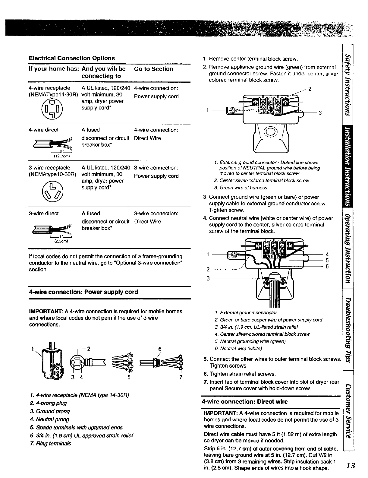
Electrical Connection Options
If your home has: And you will be Go to Section
connecting to
4-wire receptacle
(NEMAType14-30R)
A UL listed, !20/240 &wire connection:
volt minimum, 30 Power supply cord
amp, dryer power
supply cord*
©
4-wire direct A fused 4-wire connection:
disconnect or circuit Direct Wire
breaker box*
(12 7cm)
3-wire receptacle
(NEMAtypel0-30R)
A UL listed, 120/240 3-wire connection:
volt minimum, 30 Power supply cord
amp, dryer power
supply cord*
©
3-wire direct
(2.5cm)
A fused 3-wire connection:
disconnect or circuit Direct Wire
breaker box*
1, Remove center terminal block screw.
2. Remove appliance ground wire (green) from external
ground connector screw. Fasten it under center, silver
colored terminal block screw.
J2
1. External ground connector - Dotted line shows
position of NEUTRAL ground wire before being
moved to center terminal block screw
2. Center silver-colored terminal block screw
3. Green wire of harness
3. Connect ground wire (green or bare) of power
supply cable to external ground conductor screw.
Tighten screw.
4. Connect neutral wire (white or center wire) of power
supply cord to the center, silver colored terminal
screw of the terminal block.
if local codes do not permit the connection of a frame-grounding
conductor to the neutral wire, go to "Optional 3-wire connection"
section.
4-wire connection: Power supply cord
IMPORTANT: A &wire connection is required for mobile homes
and where local codes do not permit the use of 3 wire
connections.
1
\
1.4-wire receptacle (NEMA type 14-30R)
2. 4-prong plug
3. Ground prong
4. Neutral prong
5. Spade terminals with upturned ends
6. 3/4 in. (1.9 crn) UL approved strain relief
7. Ring terminals
[---2 6
3 4 5 7
1
2
3
I. External ground connector
2, Green or bare copper wire ofpower supply cord
3. 3/4 in. (1.9 cm) UL-listed strain relief
4. Center silver-colored terminal block screw
5. Neutral grounding wire (green)
6. Neutral wire (white)
5. Connect the other wires to outer terminal block screws.
Tighten screws.
6. Tighten strain relief screws.
7. Insert tab of terminal block cover into slot of dryer rear
panel Secure cover with hold-down screw.
4-wire connection: Direct wire
IMPORTANT: A &wire connection is required for mobile
homes and where local codes do not permit the use of 3
wire connections.
Direct wire cable must have 5 ft (1,52 m) of extra length
so dryer can be moved ifneeded.
Strip 5 in. (12.7 cm) of outer covedng from end of cable,
leaving bare ground wire at 5 in. (12.7 cm). Cut V/2 in.
(3.8 cm) from 3 remaining wires. Strip insulation back 1
in. (2.5 em). Shape ends of wires into a hook shape.
13
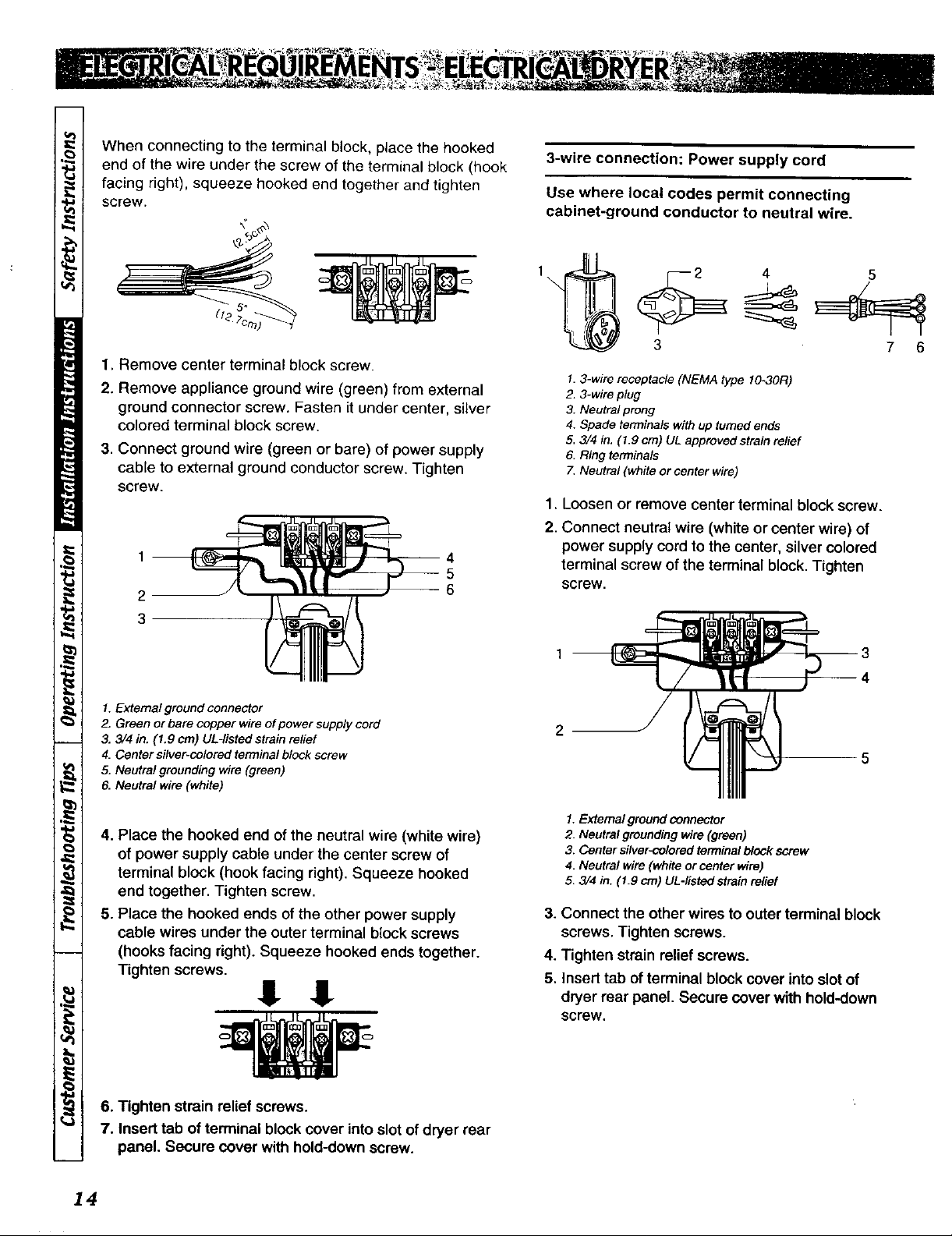
When connecting to the terminal block, place the hooked
end of the wire under the screw of the terminal block (hook
facing right), squeeze hooked end together and tighten
screw.
1. Remove center terminal block screw.
2. Remove appliance ground wire (green) from external
ground connector screw. Fasten it under center, silver
colored terminal block screw.
3. Connect ground wire (green or bare) of power supply
cable to external ground conductor screw. Tighten
screw.
1
2
3
3-wire connection: Power supply cord
Use where local codes permit connecting
cabinet-ground conductor to neutral wire.
1_ _ ____ _
3 7 6
1.3-wire receptacle (NEMA type 10_30R)
2. 3-wire plug
3. Neutral prong
4. Spade terminals with up turned ends
5. 3/4 in. (1.9 crn) UL approved strain relief
6. Ring terminals
7, Neutral (white or center wire)
.
Loosen or remove center terminal block screw.
2.
Connect neutral wire (white or center wire) of
power supply cord to the center, silver colored
terminal screw of the terminal block.Tighten
screw.
1. Extemal ground connector
2. Green or bare copper wire of power supply cord
3. 3/4 in. (1.9 cm) UL-listed strain relief
4. Center silver-colored terminal block screw
5. Neutral grounding wire (green)
6. Neutral wire (white)
4. Place the hooked end of the neutral wire (white wire)
of power supply cable under the center screw of
terminal block (hook facing right). Squeeze hooked
end together. Tighten screw.
5. Place the hooked ends of the other power supply
cable wires under the outer terminal block screws
(hooks facing right). Squeeze hooked ends together.
Tighten screws.
! !
6. Tighten strain relief screws.
7. Insert tab of terminal blockcover intoslot of dryer rear
panel. Secure cover with hold-down screw.
2
5
1. External ground connector
2. Neutral grounding wire (green)
3. Center siNer-colored terminal block screw
4. Neutral wire (white or center wire)
5. 3/4 in. (1.9 crn) UL-listed strain relief
3. Connect the other wires to outer terminal block
screws. Tighten screws.
4. Tighten strain relief screws.
5. Insert tab of terminal block cover into slot of
dryer rear panel. Secure cover with hold-down
screw.
14
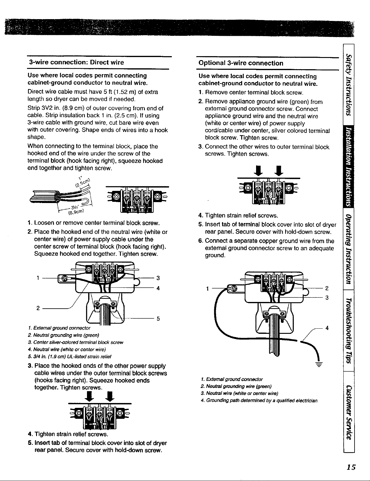
3-wire connection: Direct wire
Optional 3-wire connection
Use where local codes permit connecting
cabinet-ground conductor to neutral wire.
Direct wire cable must have 5 ft (1.52 m) of extra
length so dryer can be moved if needed.
Strip 3V2 in. (8.9 cm) of outer covering from end of
cable. Strip insulation back 1 in. (2.5 cm). If using
3-wire cable with ground wire, cut bare wire even
with outer covering. Shape ends of wires into a hook
shape.
When connecting to the terminal block, place the
hooked end of the wire under the screw of the
terminal block (hook facing right), squeeze hooked
end together and tighten screw.
1. Loosen or remove center terminal block screw.
2. Place the hooked end of the neutral wire (white or
center wire) of power supply cable under the
center screw of terminal block (hook facing right).
Squeeze hooked end together. Tighten screw.
Use where local codes permit connecting
cabinet-ground conductor to neutral wire.
1. Remove center terminal block screw.
2. Remove appliance ground wire (green) from
external ground connector screw. Connect
appliance ground wire and the neutral wire
(white or center wire) of power supply
cord/cable under center, silvercolored terminal
block screw. Tighten screw,
3. Connect the other wires to outer terminal block
screws. Tighten screws.
.It .It
4. Tighten strain relief screws.
5, Insert tab of terminal blockcover into slot of dryer
rear panel. Secure cover with hold-down screw.
6, Connect a separate copper ground wire from the
extemal ground connector screw to an adequate
ground.
1. External ground connector
2. Neutral grounding wire (green)
3. Center silver-c_oloredterminal block screw
4, Neutral wire (white or center wire)
5. 3/4 in. (1.9 cm) UL-listed strain relief
3. Place the hooked ends of the other power supply
cable wires under the outer terminal block screws
(hooks facing dght). Squeeze hooked ends
together. Tighten screws,
4. Tighten strain relief screws.
5. Insert tab of terminal blockcover into slot of dryer
rear panel. Secure cover with hold-down screw.
4
1. External ground connector
2. Neutral grounding wire (green)
3. Neutral wire (white or center wire)
4. Grounding path determined by a qualified electrician
15
Gas Dryers
(120 Volt, 60 Hertz, with 3-Prong Grounding Plug)
NOTE : The wiring diagram is located inside the
control panel, inside the control cabineL
NOTE : A qualified electrician should check the
polarity of the wall receptacles. If a voltage reading is
measured other than that illustrated, the qualified
electrician should correct the problem.
• DO NOT OPERATE OTHER APPLIANCES ON
THE SAME CIRCUIT WHEN THIS APPLIANCE
IS OPERATING. DO NOT OVERLOAD
CIRCUITS !
To reduce the risk of fire, electric shock or
personal injury, all wiring and grounding
MUST confirm with the latest edition of the
National Electrical Code ANSI/NFPA 70 or
the Canadian Electrical Code, CSA C22.1,
and such local regulations as might apply.
It is the customer's responsibility to have
the wiring and fuses checked by a qualified
electrician to make sure the laundry room
has adequate electrical power to operate
the dryer.
• The dryer is designed to be operated on a separate
branch, polarized, three-wire, effectively grounded,
120 Volt, 60 Hertz, AC (ahemating current) circuit
protected by a 15 Ampere fuse, equivalent fusetron
or circuit breaker.
• The three-prong grounding plug on the power cord
should be plugged directly into a polarized three-slot
effectively grounded receptacle rated 120 Volts AC
(alternating current) 15 Amps. Refer to Figure 22 to
determine correct polarity of the wall receptacle.
• DO NOT operate both a washer and gas dryer on the
same circuit. Use separately fused 15 Amp circuits.
To reduce the risk of an electric shock or
fire, DO NOT use an extension cord or an
adapter to connect the dryer to the
electrical power source.
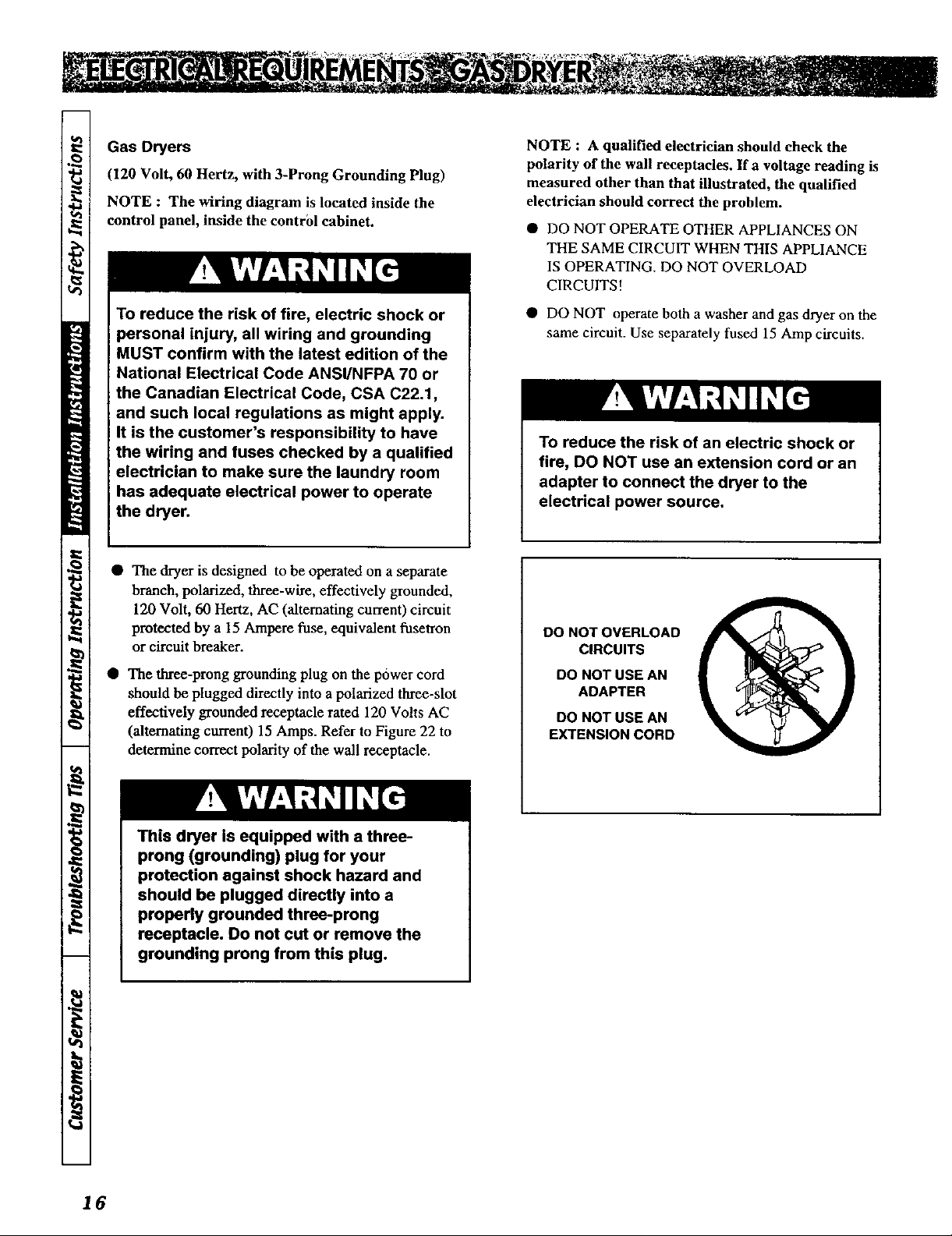
DO NOT OVERLOAD
CIRCUITS
DO NOT USE AN
ADAPTER
DO NOT USE AN
EXTENSION CORD
16
This dryer is equipped with a three-
prong (grounding) plug for your
protection against shock hazard and
should be plugged directly into a
properly grounded three-prong
receptacle. Do not cut or remove the
grounding prong from this plug.
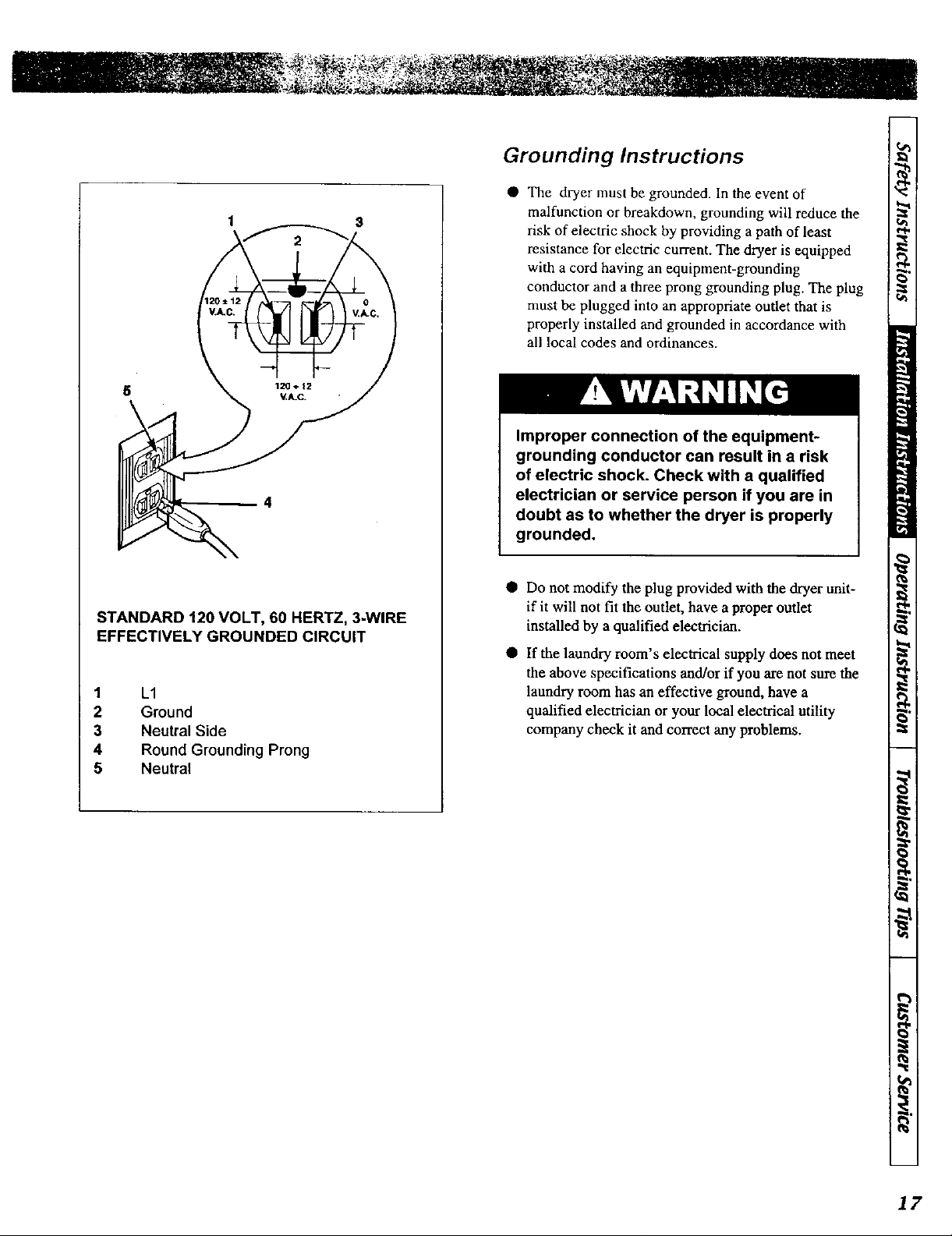
1 $
STANDARD t20 VOLT, 60 HERTZ, 3-WIRE
EFFECTIVELY GROUNDED CIRCUIT
1 L1
2 Ground
3 Neutral Side
4 Round Grounding Prong
5 Neutral
Grounding Instructions
The dryer must be grounded. In the event of
malfunction or breakdown, grounding will reduce the
risk of electric shock by providing a path of least
resistance for electric current. The dryer is equipped
with a cord having an equipment-grounding
conductor and a three prong grounding plug. The plug
must be plugged into an appropriate outlet that is
properly installed and grounded in accordance with
all local codes and ordinances.
Improper connection of the equipment-
grounding conductor can result in a risk
of electric shock. Check with a qualified
electrician or service person if you are in
doubt as to whether the dryer is properly
grounded,
• Do not modify the plug provided with the dryer unit-
if it wiU not fit the outlet, have a proper outlet
installed by a qualified electrician.
• If the laundry room's electrical supply does not meet
the above specifications and/or if you are not sure the
laundry room has an effective ground, have a
qualified electrician or your local electrical utility
company check it and correct any problems.
17
Gas Dryers
NOTE : The gas service to a gas dryer must conform
with the local codes and ordinances or, in the absence
of local codes and ordinances, with the latest edition
of the National Fuel Gas Code ANSI Z223.1/NFPA
54 or the CAN/CGA-B149, National Gas Installation
Code.
L.P (Liquefied Petroleum) Gas, 2,500 Btu/f? (93.1
MJ/m3), service must be supplied at 10_+ 1.5 in. water
column pressure.
NOTE : DO NOT connect the dryer to L.P. Gas
Service without converting the gas valve.
L.P. gas conversion:
In U.S.- Conversion must he made by a qualified
technician.
See gas valve burner base for gas conversion kit part
number.
_- Conversion must he made by a licensed
technician. Contact your local service branch if you
require further assistance.
The dryer must be isolated from the gas supply piping
system by closing its individual manual shut-off valve
during any pressure testing of the gas supply piping
system at test presure equal to or less than 1/2 psi (3.45
kPa).
NOTE : When connecting to a gas line, an equipment
shutoff valve must he installed within 6 feet (l.8m) of
the dryer. An 1/8 in. N.P.T. pipe plug must be
installed as shown. Refer to Fig
Supply line requirements:
When a rigid pipe is used it should be 112 inch IPS.
When acceptable to the gas supplier and local codes, 3/8-
inch approved tubing may be used for lengths under 6. I
m (20 feet). For lengths over 6.1 m (20 feet), larger
tubing should be used. Pipe-joint compounds resistant to
the action of L.P. gas must be used.
To reduce the risk of gas leaks, fire or
explosion:
• The dryer must be connected to the
type of gas as shown on the nameplate
located in the door recess.
• Use a new flexible stainless steel
connector.
• Use pipe joint compound insoluble in
L.P. (Liquefied Petroleum) Gas, or
Teflon tape, on all pipe threads.
• Purge air and sediment from gas supply
line before connecting it to the dryer.
Before tightening the connection, purge
remaining air from gas line to dryer
until odor of gas is detected. This step
is required to prevent a gas valve
contamination.
• Do not use an open flame to check for
gas leaks. Use a non-corrosive leak
detection fluid.
• Any dis-assembly requiring the use of
tools must be per[ormed by an
authorized qualified service person.
Provide a rigid gas supply line to the dryer location.
/n U.S.- An individual manual shutoff valve must be
installed within 1.8m (6 feet) of the dryer in accordance
with the National Fuel Gas Code ANSI Z223.1 *.
In Canada- An individual manual shutoff valve must be
installed in accordance with the B-149 installation codes,
CAN/CGA B-149.1 and B-149.2".
18
Exhaust System Materials
A clothes dryer produces combustible
lint.
To reduce the risk of fire or gas
accumulation, the dryer MUST be
exhausted to the outdoors.
This gas appliance contains or produces
a chemical or chemicals which can cause
death or serious illness and which are
known to the State of California to cause
cancer, birth defects, or other
reproductive harm. To reduce the risk
from fuel combustion, make sure this
appliance is installed, operated, and
maintained according to the instructions
in this manual.
To reduce the risk of fire and the
accumulation of combustion gases, DO
NOT exhaust dryer air into a window well,
gas vent, chimney or enclosed,
unventilated area, such as an attic, wall,
ceiling, crawl space under a building or
concealed space of a building.
To reduce the risk of fire, DO NOT use
plastic or thin foil ductiong to exhaust
the dryer.
Exhaust system materials are not supplied with the dryer.
Exhaust duct must be four inches (10.2 cm) in diameter
having no obstructions. Rigid metal duct is
recommended. Non-combustible flexible metal duct is
acceptable. Do not use plastic or thin foil ducting,
because it contributes to poor drying performance and
collects lint, which can lead to a fire hazard.
Never install flexible duct in concealed spaces, such as a
wall or ceiling.
DO NOT use sheet metal screws on exhaust pipe joints
or other fastening means which extend into the duct that
could catch lint and reduce the efficiency of the exhaust
system. Secure all joints with duct tape.
Exhaust System
IMPORTANT : Keep exhaust duct as short as
possble.
NOTE : Be certain old ducts are cleaned before
installing your new dryer.
For best drying results, recommended maximum length
of exhaust system is shown in Table 1.
To prevent backdraft when dryer is not in operation,
outer end of exhaust pipe must have a weather hood with
hinged dampers (obtain locally).
19
 Loading...