

Page 1
OWNER'S MANUAL
DRYER
Read this owner’s manual thoroughly before operating the appliance and keep it handy for
reference at all times.
ENGLISH ESPAÑOL
DLE3400*, DLG3401*
MFL70442642
Rev.01_121819
www.lg.com
Copyright © 2019 LG Electronics Inc. All Rights Reserved.
Page 2

2
TABLE OF CONTENTS
3 PRODUCT FEATURES
4 SAFETY INSTRUCTIONS
4 IMPORTANT SAFETY INSTRUCTIONS
9 PRODUCT OVERVIEW
9 Parts
9 Accessories
10 INSTALLATION
10 Installation Overview
10 Product Specifications
11 Installation Location Requirements
12 Clearances
14 Leveling the Dryer
15 Reversing the Door
16 Installing the Side Vent Kit
17 Stacking the Dryer
18 Venting the Dryer
20 Connecting Gas Dryers
22 Connecting Electric Dryers
27 Special Electrical Requirements
27 Final Installation Check
28 Installation Test (Duct Check)
39 MAINTENANCE
39 Regular Cleaning
41 TROUBLESHOOTING
41 FAQs: Frequently Asked Questions
41 User Support Videos
42 Before Calling for Service
47 WARRANTY
31 OPERATION
31 Using the Dryer
32 Check the Lint Filter Before Every Load
32 Sorting Laundry
32 Loading the Dryer
33 Control Panel
35 Cycle Guide
36 Cycle Modifier Buttons
36 Option Buttons
37 Special Functions
38 SMART FUNCTIONS
38 LG ThinQ Application
38 Smart Diagnosis™ Feature
Page 3
PRODUCT FEATURES
T
I
F
I
PRODUCT FEATURES
3
Easy-to-Use Control Panel
Rotate the cycle selector knob to select the desired dry cycle. Add cycle options or adjust settings with the
touch of a button.
Easy-Access Reversible Door
The wide-opening door provides easy access for loading and unloading. The door hinge can be reversed to
adjust for installation location.
Flow Sense™ Duct Blockage Sensing System Indicator
The Flow Sense™ duct blockage sensing system detects and alerts you to restrictions in the installed
household ductwork that reduce exhaust airflow through the dryer. If you see the alert: Clean or repair the
ducts to remove the restrictions. Keep your ducts clean to help increase efficiency and reduce long drying
times caused by blocked ducts.
Smart Diagnosis™
Should you experience any technical difficulty with your dryer, it has the capability of transmitting data via your
telephone to the Customer Information Center. The call center agent records the data transmitted from your
machine and uses it to analyze the issue, providing a fast and effective diagnosis.
G
S
N
E
D
C
E
D
R
E
I
ENGLISH
Page 4
SAFETY INSTRUCTIONS
4
SAFETY INSTRUCTIONS
READ ALL INSTRUCTIONS BEFORE USE
Your safety and the safety of others are very important.
We have provided many important safety messages in this manual and on your appliance. Always
read and follow all safety messages.
This is the safety alert symbol.
This symbol alerts you to potential hazards that can kill or injure you and others.
All safety messages will follow the safety alert symbol and either the word WARNING or
CAUTION. These words mean:
WARNING
You may be killed or seriously injured if you do not follow instructions.
CAUTION
You may be slightly injured or cause damage to the product if you do not follow instructions.
All safety messages will tell you what the potential hazard is, tell you how to reduce the chance of
injury, and tell you what may happen if the instructions are not followed.
IMPORTANT SAFETY INSTRUCTIONS
WARNING
To reduce the risk of explosion, fire, death, electric shock, scalding or injury to persons
when using this product, follow basic precautions, including the following:
FIRE OR EXPLOSION HAZARD
• Do not store or use gasoline or other flammable vapors and liquids in the vicinity of this or any other
appliance.
• WHAT TO DO IF YOU SMELL GAS
− Do not try to light any appliance.
− Do not touch any electrical switch; do not use any phone in your building.
− Clear the room, building or area of all occupants.
− Immediately call your gas supplier from a neighbor’s phone. Follow the gas supplier’s instructions.
− If you cannot reach your gas supplier, call the fire department.
• Installation and service must be performed by a qualified installer, service agency or your gas supplier.
Page 5

SAFETY INSTRUCTIONS
5
INSTALLATION
• Before use, the appliance must be properly installed as described in this manual.
• Connect to a properly rated, protected, and sized power circuit to avoid electrical overload.
• To reduce the risk of severe injury or death, follow all installation instructions.
• The appliance must be installed and electrically grounded by qualified service personnel in accordance
with local codes.
• Disconnect the power cord, house fuse or circuit breaker before installing or servicing the appliance.
• When moving or installing the product in a different location, call qualified service personnel for
installation and service.
• Keep packing materials out of the reach of children. Packaging material can be dangerous for children.
There is a risk of suffocation.
• Moving or installation of the appliance requires two or more people.
• This appliance is not designed for maritime use or for mobile installations such as in RVs, trailers, or
aircraft.
• Store and install the appliance where it will not be exposed to temperatures below freezing or exposed
to outdoor weather conditions.
• This appliance must be positioned near to an electrical power supply.
• Do not, under any circumstances, cut or remove the third (ground) prong from the power cord.
• When installing or moving the appliance, be careful not to pinch, crush, or damage the power cord.
• Do not install the appliance in humid spaces.
• Destroy the carton, plastic bag, and other packing materials after the appliance is unpacked. Children
might use them for play. Cartons covered with rugs, bedspreads, or plastic sheets can become airtight
chambers.
• Adhere to all industry recommended safety procedures including the use of long sleeved gloves and
safety glasses.
• Never attempt to operate this appliance if it is damaged, malfunctioning, partially disassembled, or has
missing or broken parts, including a damaged cord or plug.
• Do not install a clothes dryer with flexible plastic venting materials. If flexible metal (foil type) duct is
installed, it must be of a specific type identified by the appliance manufacturer as suitable for use with
clothes dryers. Flexible venting materials are known to collapse, be easily crushed, and trap lint. These
conditions will obstruct clothes dryer airflow and increase the risk of fire.
• Place the dryer at least 18 inches above the floor for a garage installation.
• Do not use sheet metal screws or other fasteners which extend into the duct that could catch lint and
reduce the efficiency of the exhaust system. Secure all joints with duct tape.
• Use only rigid, semi-rigid or flexible metal 4-inch diameter duct inside the dryer cabinet or for exhausting
to the outside. Use of plastic or other combustible ductwork may cause a fire. Punctured ductwork may
cause a fire if it collapses or becomes otherwise restricted in use or during installation.
• The exhaust duct must be 4 inches (10.2 cm) in diameter with no obstructions. The exhaust duct should
be kept as short as possible. Make sure to clean any old ducts before installing your new dryer.
• Rigid, semi-rigid or flexible metal ducting is recommended for use between the dryer and the wall. All
non-rigid metal transition duct must be UL-listed. Use of other materials for transition duct could affect
drying time.
• Ductwork is not provided with the dryer, and you should obtain the necessary ductwork locally. The end
cap should have hinged dampers to prevent backdraft when the dryer is not in use.
ENGLISH
Page 6

SAFETY INSTRUCTIONS
6
• Gas dryers MUST be exhausted to the outside.
• The dryer exhaust system must be exhausted to the outside of the dwelling. If the dryer is not
exhausted outdoors, some fine lint and large amounts of moisture will be expelled into the laundry area.
An accumulation of lint in any area of the home may create a health and fire hazard.
• Do not install near another heat source such as a stove, oven or heater.
• Keep area around the exhaust opening and adjacent surrounding areas free from the accumulation of
lint, dust, and dirt.
• The appliance must not be supplied through an external switching device, such as a timer, or connected
to a circuit that is regularly switched on and off by a utility.
OPERATION
• Repair or immediately replace all power cords that have become frayed or otherwise damaged. Do not
use a cord that shows cracks or abrasion damage along its length or at either end.
• If you detect a strange sound, a chemical or burning smell, or smoke coming from the appliance, unplug
it immediately, and contact an LG Electronics customer information center.
• Never unplug the appliance by pulling on the power cord. Always grip the plug firmly and pull straight
out from the outlet.
• Do not use an extension cord or adapter with this appliance.
• Do not grasp the power cord or touch the appliance controls with wet hands.
• Do not modify or extend the power cord.
• If the product has been submerged, contact an LG Electronics customer information center for
instructions before resuming use.
• Do not store or use gasoline or other flammable vapors and liquids in the vicinity of this or any other
appliance.
• Keep the area underneath and around your appliances free of combustible materials (lint, paper, rags,
etc.), gasoline, chemicals and other flammable vapors and liquids.
• This appliance is not intended for use by persons (including children) with reduced physical, sensory or
mental capabilities, or lack of experience and knowledge, unless they have been given supervision or
instruction concerning the use of the appliance by a person responsible for their safety.
• Read all instructions before using the appliance and save these instructions.
• Use this appliance only for its intended purpose.
• Do not abuse, sit on, or stand on the door of the appliance.
• Do not allow children to play on, in or with the appliance. Close supervision of children is necessary
when the appliance is used near children.
• Do not tamper with controls.
• In the event of a gas leak (propane gas, LP gas, etc.) do not operate this or any other appliance. Open
a window or door to ventilate the area immediately.
• Under certain conditions, hydrogen gas may be produced in a hot-water system that has not been used
for two weeks or more. HYDROGEN GAS IS EXPLOSIVE. If the hot-water system has not been used
for such a period, before using the appliance turn on all hot water faucets and let the water flow from
each for several minutes. This will release any accumulated hydrogen gas. As the gas is flammable, do
not smoke or use an open flame during this time.
Page 7

SAFETY INSTRUCTIONS
• Fix the drain hose securely in place.
• Do not put oily or greasy clothing, candles or flammable materials on top of the appliance.
• Do not use fabric softeners or products to eliminate static unless recommended by the manufacturer of
the fabric softener or product.
• Do not reach into the appliance if the drum is moving.
• Do not dry articles that have been previously cleaned in, washed in, soaked in, soiled with or spotted
with gasoline, dry cleaning solvents, vegetable oil, cooking oil or other flammable or explosive
substances, as they give off vapors that could ignite or explode.
• Do not use heat to dry articles containing foam rubber or similarly textured rubber-like materials.
• Do not store plastic, paper, or clothing that may burn or melt on top of the dryer during operation.
• Always check the inside of the appliance for foreign objects.
• Gas appliances can cause minor exposure to four potentially hazardous substances, namely benzene,
carbon monoxide, formaldehyde, and soot, caused primarily by the incomplete combustion of natural
gas or LP fuels.
• Properly adjusted dryers will minimize incomplete combustion. Exposure to these substances can be
minimized further by properly venting the dryer to the outdoors.
• Do not place items exposed to cooking oils in your dryer. Items contaminated with cooking oils may
contribute to a chemical reaction that could cause a load to catch fire.
To reduce the risk of fire due to contaminated loads, the final part of a tumble dryer cycle occurs without
heat (cool down period). Avoid stopping a tumble dryer before the end of the drying cycle unless all
items are quickly removed and spread out so that the heat is dissipated.
7
ENGLISH
• Do not let children or pets climb inside the dryer drum.
• Do not put living animals such as pets inside the product.
• Do not put any part of your body, such as your hands or feet, or metal objects under the product.
• Do not let your hand get pinched when opening or closing the dryer door.
MAINTENANCE
• Do not repair or replace any part of the appliance. All repairs and servicing must be performed by
qualified service personnel unless specifically recommended in this Owner’s Manual. Use only
authorized factory parts.
• Do not disassemble or repair the appliance by yourself.
• Remove any dust or foreign matter from the power plug pins.
• Disconnect this appliance from the power supply before cleaning and attempting any user maintenance.
Turning the controls to the OFF position does not disconnect this appliance from the power supply.
• Remove the door before the appliance is removed from service or discarded to avoid the danger of
children or small animals getting trapped inside.
• Unplug the appliance before cleaning to avoid the risk of electric shock.
• Clean the lint filter before or after each load.
• The interior of the appliance and exhaust duct should be cleaned periodically by qualified service
personnel.
Page 8

SAFETY INSTRUCTIONS
8
GROUNDING INSTRUCTIONS
• Improper connection of the equipment-grounding conductor can result in a risk of electric shock. Check
with a qualified electrician or service personnel if you are in doubt whether the appliance is properly
grounded. Do not modify the plug provided with the appliance; if it will not fit the outlet, have a proper
outlet installed by a qualified electrician.
• The appliance must be grounded. In the event of a malfunction or breakdown, grounding will reduce
the risk of electric shock by providing a path of least resistance for electric current. The appliance is
equipped with a cord having an equipment-grounding conductor and a grounding plug. The plug must
be plugged into an appropriate outlet that is installed and grounded in accordance with all local codes
and ordinances.
• This dryer must be plugged into a properly grounded outlet. Electrical shock may result if the dryer is
not properly grounded. Have the wall outlet and circuit checked by a qualified electrician to make sure
the outlet is properly grounded. Failure to follow these instructions may create an electric shock hazard
and/or a fire hazard.
Risk of Fire
Install the clothes dryer according to the manufacturer’s instructions and local codes.
• Clothes dryer installation must be performed by a qualified installer.
• Do not install a clothes dryer with flexible plastic venting materials. If flexible metal (foil type) duct is
installed, it must be of a specific type identified by the appliance manufacturer as suitable for use with
clothes dryers. Flexible venting materials are known to collapse, be easily crushed, and trap lint. These
conditions will obstruct clothes dryer airflow and increase the risk of fire.
• To reduce the risk of severe injury or death, follow all installation instructions.
• Do not install a booster fan in the exhaust duct.
• Install all clothes dryers in accordance with the installation instructions of the manufacturer of the dryer.
SAVE THESE INSTRUCTIONS
Page 9
PRODUCT OVERVIEW
PRODUCT OVERVIEW
9
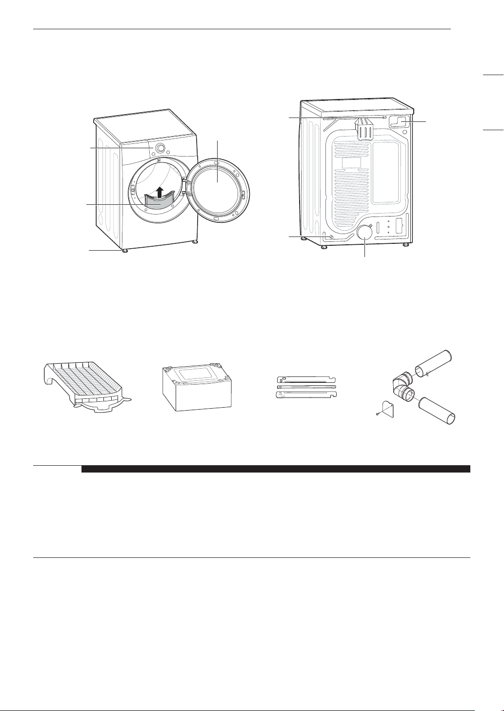
Parts
Reversible
door
Control panel
Lint filter
Leveling feet
Accessories
Optional Accessories (Sold Separately)
Power
Cord
(gas
models)
Gas
connection
(gas models)
ENGLISH
Terminal
Block
Access
Panel
(electric
models)
Exhaust Duct Outlet
Drying Rack Pedestal Stacking kit Side vent kit
Kit No. 383EEL9001B
NOTE
• For your safety and extended product life, use only authorized components. The manufacturer is not
responsible for product malfunction or accidents caused by the use of unauthorized components or
parts.
• The images in this manual may be different from the actual components and accessories which are
subject to change by the manufacturer without prior notice for product improvement purposes.
Page 10
INSTALLATION
10
INSTALLATION
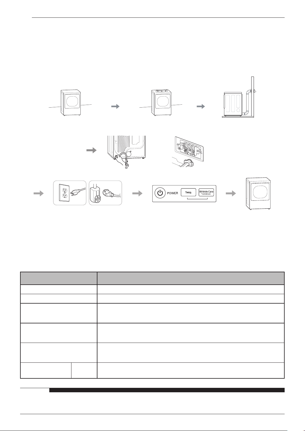
Installation Overview
Please read the following installation instructions first after purchasing this product or transporting it to
another location.
Check and choose the
proper location
Connect the Gas dryer Connect the Electric dryer
Gas dryer Installation test Test runElectric dryer
Plug in the power cord
Level the dryer Vent the dryer
Product Specifications
The appearance and specifications listed in this manual may vary due to constant product improvements.
Dryer Models DLE3400* / DLG3401*
Description Non-steam Dryer
Electrical requirements Please refer to the rating label for detailed information.
Gas requirements
Dimensions
Net weight
Drying capacity
Normal
Cycle
NG: 4 - 10.5-inch (10.2 - 26.7 cm) WC
LP: 8 - 13-inch (20.4 - 33.1 cm) WC
27” (W) X 30.2” (D) X 39” (H), 51.4” (D with door open)
68.6 cm (W) X 76.5 cm (D) X 99 cm (H), 130.5 cm (D with door open)
Gas : 123.02 lb (55.8kg)
Electric : 120.15 lb (54.5kg)
IEC 7.4 cu.ft. (22.5 lb/10.2 kg)
NOTE
• Model numbers can be found on the cabinet inside the door.
Page 11
Installation Location Requirements
INSTALLATION
11
WARNING
• Read all installation instructions completely before installing and operating your dryer! It is important
that you review this entire manual before installing and using your dryer. Detailed instructions
concerning electrical connections, gas connections, and exhaust requirements are provided on the
following pages.
The installation requires:
• A location that allows for proper exhaust installation. A gas dryer must be exhausted to the outdoors.
See Venting the Dryer.
• A grounded electrical outlet located within 2 ft. (61 cm) of either side of the dryer. See Connecting
Electric Dryers.
• A sturdy floor to support the total dryer weight of 200 lb (90.7 kg). The combined weight of a companion
appliance should also be considered.
• No other fuel-burning appliance can be installed in the same closet as a dryer.
• Additional clearances might be required for wall, door and floor moldings.
• Companion appliance spacing should also be considered.
NOTE
• The floor must be level, with a maximum slope of 1 inch (2.5 cm) under the entire dryer. Clothes may
not tumble properly, and automatic sensor cycles may not operate correctly if the dryer is not level.
• For garage installation, you will need to place the dryer at least 18 inches (45.7 cm) above the floor.
The standard pedestal height is 15 inches (38 cm). You will need 18 inches (45.7 cm) from the garage
floor to the bottom of the dryer.
• Do not operate your dryer at temperatures below 45 °F (7 °C). At lower temperatures, the dryer might
not shut off at the end of an automatic cycle. This can result in longer drying times.
• The dryer must not be installed or stored in an area where it will be exposed to water and/or weather.
• Check code requirements that limit, or do not permit, installation of the dryer in garages, closets,
mobile homes or sleeping quarters. Contact your local building inspector.
ENGLISH
Page 12
INSTALLATION
(
(25 mm)
(25 mm)
(686 mm)
12
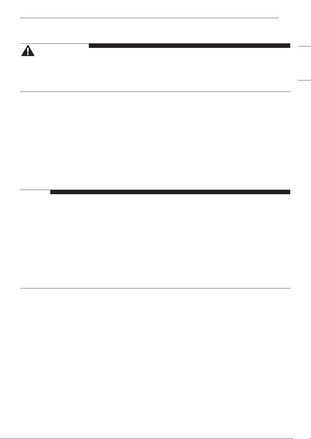
Clearances
2*
48 in.
2
(310 cm
)
2*
24 in.
155 cm2)
Closet Door Vent
Requirements
1"*
(25 mm)
3"
*
(76 mm)
3"
*
(76 mm)
1"
18" min.*
(457 mm)
30.2"
(765mm)
14" max.*
(356 mm)
5"**
(127 mm)
27"
1"
0"
(0 mm)
39"
(990 mm)
1"*
(25 mm)
18" min.*
(457 mm)
30.2"
(765mm)
1"
(25 mm)
14" max.*
(356 mm)
5"**
(127 mm)
27"
(686 mm)
1"
(25 mm)
Installation Spacing for Recessed Area or Closet Installation
The following clearances are recommended for this dryer. This dryer has been tested for clearances of
1 inch (2.5 cm) on the sides and rear. Recommended clearances should be considered for the following
reasons:
• Additional clearances should be considered for ease of installation and servicing.
• Additional clearances should be considered on all sides of the dryer to reduce noise transfer. For closet
installation, with a door, minimum ventilation openings in the top and bottom of the door are required.
Louvered doors with equivalent ventilation openings are acceptable.
Closet Ventilation Requirements
Closets with doors must have both an upper and lower vent to prevent heat and moisture buildup in the
closet. One upper vent opening with a minimum opening of 48 sq. in. (310 cm2) must be installed no lower
than 6 feet above the floor. One lower vent opening with a minimum opening of 24 sq. in. (155 cm2) must
be installed no more than one foot above the floor. Install vent grills in the door or cut down the door at the
top and bottom to form openings. Louvered doors with equivalent ventilation openings are also acceptable.
NOTE
• There should be at least a little space around the dryer (or any other appliance) to eliminate the
transfer of vibration from one appliance to another. If there is enough vibration, it could cause
appliances to make noise or come into contact, causing paint damage and further increasing noise.
Page 13
INSTALLATION
(155 cm
(25 mm)
(25 mm)
(686 mm)
7" *
7" *
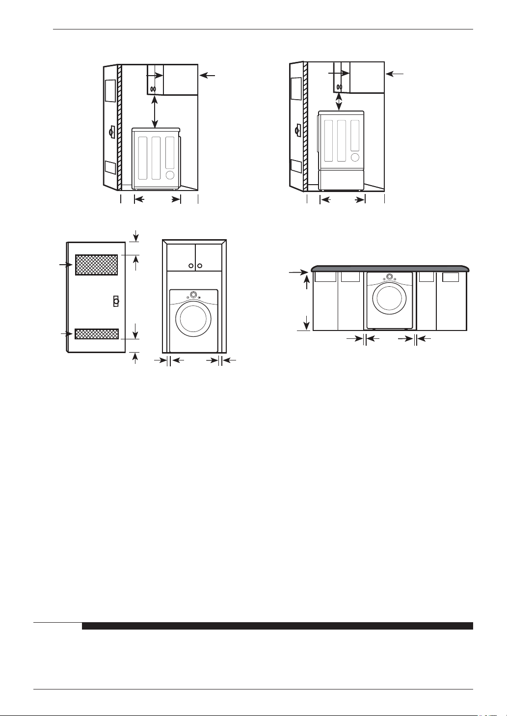
Installation Spacing for Recessed Area or Closet, with Stacked Washer and
Dryer
*
6"
(152 mm)
77 ½"
(1968 mm)
1"
27"
1"
48 in.
(310 cm
24 in.
3"
*
2*
2
)
2*
2
)
(76 mm)
*
3"
(76 mm)
1"
*
(25 mm)
5 ½"
**
(140 mm)
* Required spacing
** For side or bottom venting, 2-inch (5.1 cm) of spacing is allowed.
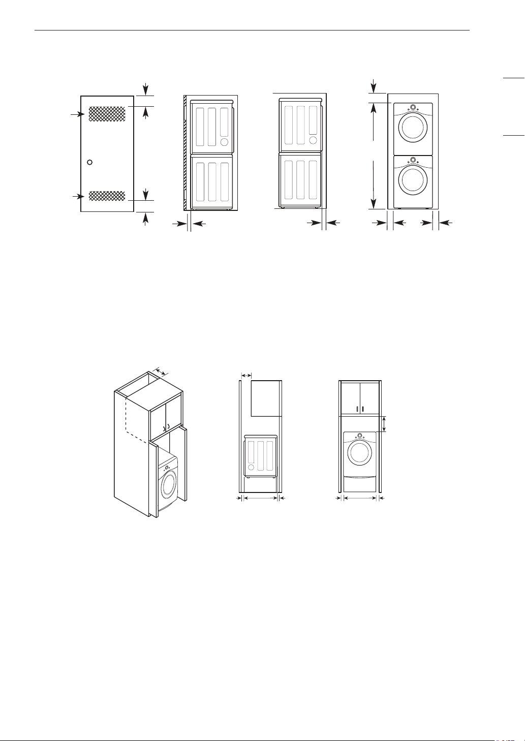
Installation Spacing for Cabinet
13
ENGLISH
For cabinet installation with a door, minimum ventilation openings in the top of the cabinet are required.
* Required spacing
(178 mm)
(178 mm)
5"*
(127 mm)
30.2"
(765 mm)
1"*
(25 mm)
1"
(25 mm)
27"
(686 mm)
1"
(25 mm)
9" *
(229 mm)
Page 14
INSTALLATION
14
Leveling the Dryer
WARNING
• Use long-sleeved gloves and safety glasses.
• The appliance is heavy. Two or more people
are required when installing the dryer.
NOTE
• Adjust the leveling feet only as far as
necessary to level the dryer. Extending the
leveling feet more than necessary may cause
the dryer to vibrate.
• To ensure that the dryer provides optimal
drying performance, it must be level. To
minimize vibration, noise, and unwanted
movement, the floor must be a perfectly level,
solid surface.
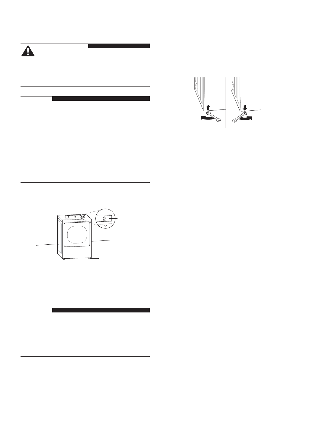
Use an adjustable wrench to turn the leveling
2
feet. Unscrew the legs to raise the dryer or
screw in the legs to lower it. Raise or lower
with the leveling feet until the dryer is level
from side to side and front to back. Make sure
that all four leveling feet are in firm contact
with the floor.
Position the dryer in the final location. Place a
1
level across the top of the dryer.
Level
Leveling Feet
• All four leveling feet must rest solidly on the
floor. Gently push on the top corners of the
dryer to make sure that the dryer does not
rock from corner to corner.
NOTE
• If you are installing the dryer on the optional
pedestal, you must use the leveling feet on the
pedestal to level the dryer. The dryer leveling
feet should be fully retracted.
Page 15
Reversing the Door
INSTALLATION
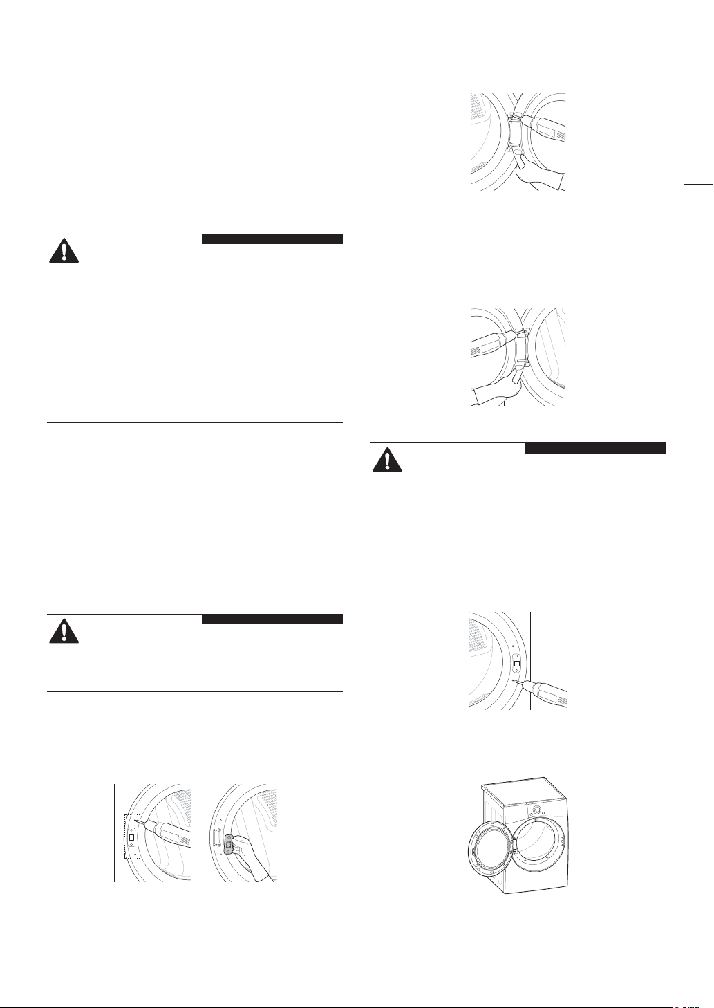
While supporting the door, remove the 2
2
screws on the door hinge. Remove the door.
15
Tools Required
• Phillips screwdriver
• Large flat blade screwdriver (recommended for
hinge screws if they are tight or your Phillips
screwdriver is worn)
• Small flat blade screwdriver (for lifting out parts)
WARNING
• Support the door with a stool or box that fits
under the door, or have an assistant support
the weight of the door.
• Avoid dropping the door.
• Unplug the dryer or turn off power at the main
circuit breaker before beginning door reversal.
• Always reverse the door BEFORE stacking
the dryer on top of the washer.
Door Reversal Instructions
The instructions here are for changing the door
swing from a right to a left side hinge. If the
door has been reversed, and it is necessary to
change it back, use care when following these
instructions. Some of the illustrations and the left/
right references will be reversed, and you will need
to read the instructions carefully.
Turn the door upside down and line up the
3
holes in the hinge with the holes on the
opposite side of the cabinet. Reinstall the door
with the screws removed in step 2.
WARNING
• Be sure to support the weight of the door
before installing the hinge screws.
Install the two decorative screws, the latch,
4
and two latch screws removed in step 1 on the
opposite side from which they were removed.
ENGLISH
WARNING
• Be sure to support the weight of the door
before removing the hinge screws.
Open the door and remove the two decorative
1
screws, two latch screws, and the latch on the
catch side with a screwdriver. Save these for
step 4.
Check that the door closes properly.
5
Page 16
INSTALLATION
16
Installing the Side Vent Kit
WARNING
• Use long-sleeved gloves and safety glasses.
• Use a heavy metal vent.
• Do not use plastic or thin foil ducts.
• Clean old ducts before installing this dryer.
Your new dryer is configured to vent to the rear.
It can also vent to the bottom or side (right-side
venting is not available on gas models).
Preassemble a 4-inch (10.2 cm) elbow to the
3
next 4-inch (10.2 cm) duct section, and secure
all joints with duct tape. Be sure that the male
end of the elbow faces AWAY from the dryer.
Insert the elbow/duct assembly through the
side opening and press it onto the adapter
duct. Secure it in place with duct tape. Be
sure that the male end of the duct protrudes
1.5 inches (3.8 cm) to connect the remaining
ductwork. Attach the cover plate to the back of
the dryer with the included screw.
An adapter kit, part number 383EEL9001B, may
be purchased from your LG retailer. This kit
contains duct components necessary to change
the dryer vent location.
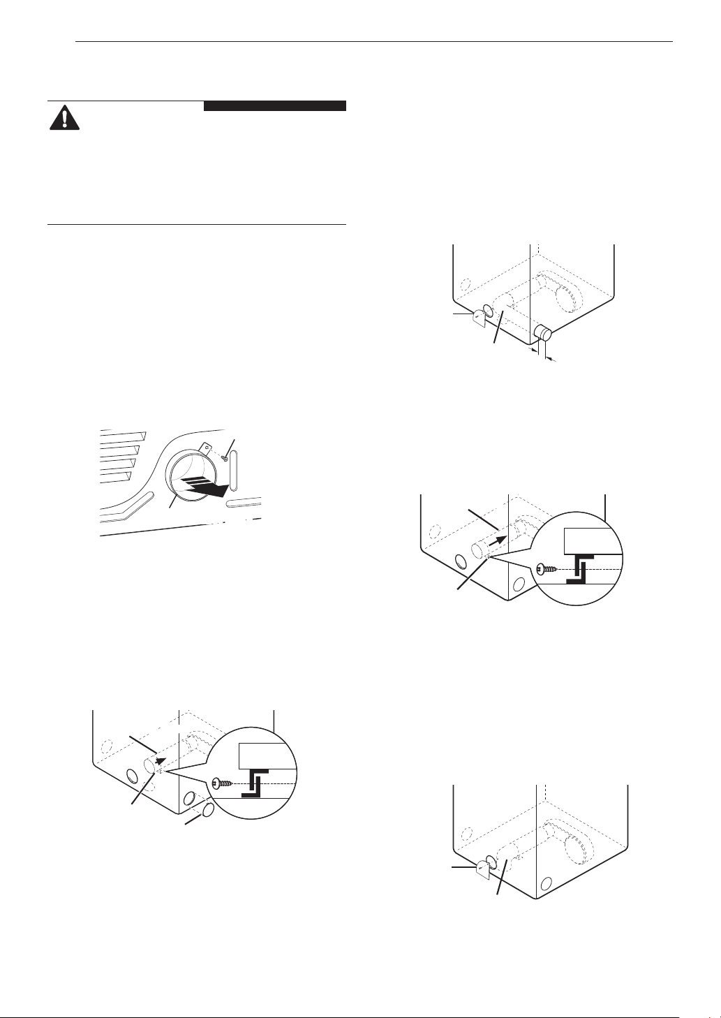
Remove the rear exhaust duct retaining screw.
1
Pull out the exhaust duct.
Retaining
Screw
Rear Exhaust Duct
Option 1: Side Venting
Press the tabs on the knockout and carefully
2
remove the knockout for the desired vent
opening. (Right-side venting is not available on
gas models.) Press the adapter duct onto the
blower housing and secure to the base of the
dryer as shown.
Adapter Duct
Cover
Plate
Elbow
1½” (38 mm)
Option 2: Bottom Venting
Press the adapter duct onto the blower
2
housing and secure it to the base of the dryer
as shown.
Adapter Duct
Bracket
Insert the 4-inch (10.2 cm) elbow through the
3
rear opening and press it onto the adapter
duct. Be sure that the male end of the elbow
faces down through the hole in the bottom of
the dryer. Secure it in place with duct tape.
Attach the cover plate to the back of the dryer
with the included screw.
Bracket
Knockout
Cover
Plate
Elbow
Page 17
INSTALLATION
17
Stacking the Dryer
Stacking Kit Installation
This stacking kit includes:
• Two (2) side rails
• One (1) front rail
• Four (4) screws
Tools Needed for Installation:
• Phillips screwdriver
WARNING
• The weight of the dryer and the height of
installation make this stacking procedure too
risky for one person. Two or more people are
required when installing the stacking kit.
• Do not use the stacking kit with a gas dryer
in potentially unstable conditions such as a
mobile home.
• Place the washer on a solid, stable, level
floor capable of supporting the weight of both
appliances.
• Do not stack the washer on top of the dryer.
• If appliances are already installed, disconnect
them from all power, water, or gas lines and
from draining or venting connections.
To ensure safe and secure installation, please
observe the following instructions.
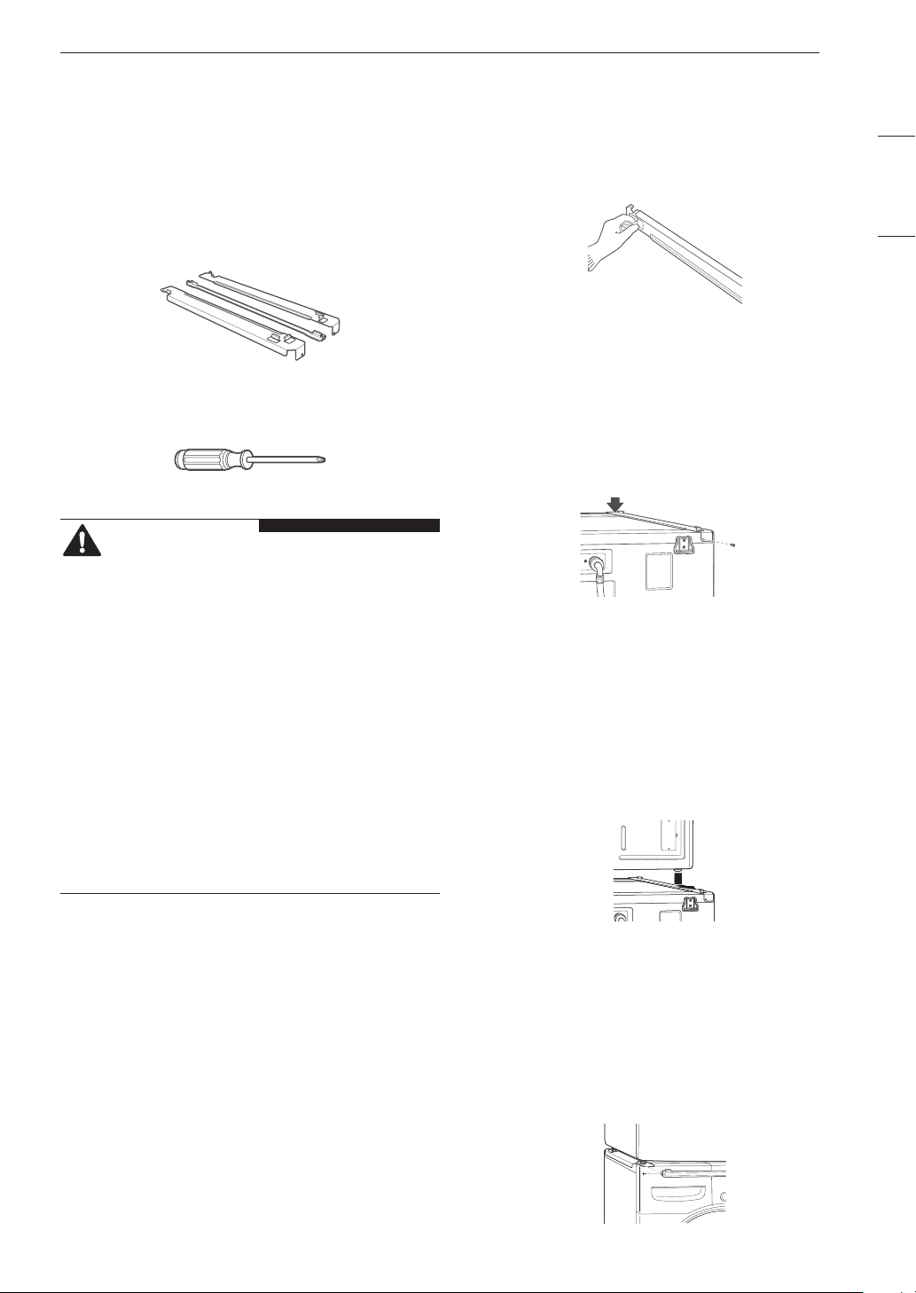
Make sure the surface of the washer is clean
1
and dry. Remove paper backing from the tape
on one of the stacking kit side brackets.
Fit the side bracket to the side of the washer
2
top as shown. Firmly press the adhesive area
of the bracket to the washer surface. Secure
the side bracket to the washer with a screw on
the back side of the bracket. Repeat steps 1
and 2 to attach the other side bracket.
Place the dryer on top of the washer, fitting the
3
dryer feet into the side brackets as illustrated.
Avoid finger injuries; do not allow fingers to be
pinched between the washer and dryer.
Slowly slide the dryer toward the back of the
washer until the side bracket stoppers catch
the dryer feet.
ENGLISH
Insert the front rail between the bottom of the
4
dryer and the top of the washer. Push the
front rail toward the back of the washer until it
comes in contact with the side rail stoppers.
Install the two remaining screws to secure the
front rail to the side rails.
Page 18
INSTALLATION
a
a
b
18
Venting the Dryer
WARNING
• Do not crush or collapse ductwork.
• Do not allow ductwork to rest on or contact
sharp objects.
• If connecting to existing ductwork, make sure
it is suitable and clean before installing the
dryer.
• Venting must conform to local building codes.
• Gas dryers MUST exhaust to the outdoors.
• Use only 4-inch (10.2 cm) rigid, semi-rigid
or flexible metal ductwork inside the dryer
cabinet and for venting outside.
• To reduce the risk of fire, combustion, or
accumulation of combustible gases, DO
NOT exhaust dryer air into an enclosed and
unventilated area, such as an attic, wall,
ceiling, crawl space, chimney, gas vent, or
concealed space of a building.
• To reduce the risk of fire, DO NOT exhaust the
dryer with plastic or thin foil ducting.
• The exhaust duct must be 4 inches (10.2 cm)
in diameter with no obstructions. The exhaust
duct should be kept as short as possible.
Make sure to clean any old ducts before
installing your new dryer.
• Rigid, semi-rigid or flexible metal ducting is
recommended for use between the dryer and
the wall. All non-rigid metal transition duct
must be UL-listed. Use of other materials for
transition duct could affect drying time.
• DO NOT use sheet metal screws or other
fasteners which extend into the duct that could
catch lint and reduce the efficiency of the
exhaust system. Secure all joints with duct
tape.
• Do not exceed the recommended duct length
limitations noted in the chart. Failure to follow
these instructions may result in extended
drying times, fire or death.
WARNING
• Ductwork is not provided with the dryer. You
should obtain the necessary ductwork locally.
The vent hood should have hinged dampers to
prevent backdraft when the dryer is not in use.
• The total length of flexible metal duct must not
exceed 8 ft. (2.4 m).
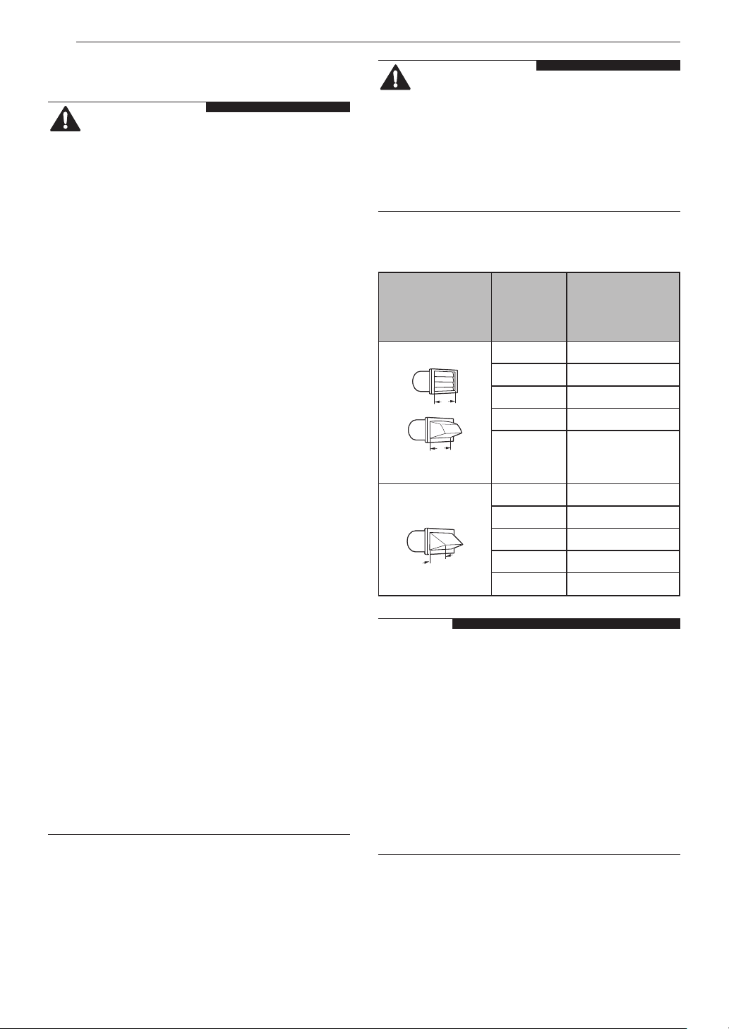
Ductwork
Maximum
length of 4-inch
diameter rigid
metal duct
Wall Cap Type
Recommended
a: 4” (10.2 cm)
Use only for short
run installations
b: 2.5” (6.35 cm)
Number
of 90°
Elbows
0 65 ft.(19.8 m)
1 55 ft.(16.8 m)
2 47 ft.(14.3 m)
3 36 ft.(11.0 m)
4 28 ft.(8.5 m)
0 55 ft.(16.8 m)
1 47 ft.(14.3 m)
2 41 ft.(12.5 m)
3 30 ft.(9.1 m)
4 22 ft.(6.7 m)
NOTE
• Deduct 6 ft. (1.8 m) for each additional elbow.
Do not use more than four 90° elbows.
• In Canada, only those foil-type flexible ducts,
if any, specifically identified for use with the
appliance by the manufacturer should be
used. In the United States, only those foil-type
flexible ducts, if any, specifically identified for
use with the appliance by the manufacturer
and that comply with the Outline for Clothes
Dryer Transition Duct, Subject 2158A, should
be used.
Page 19
INSTALLATION
19
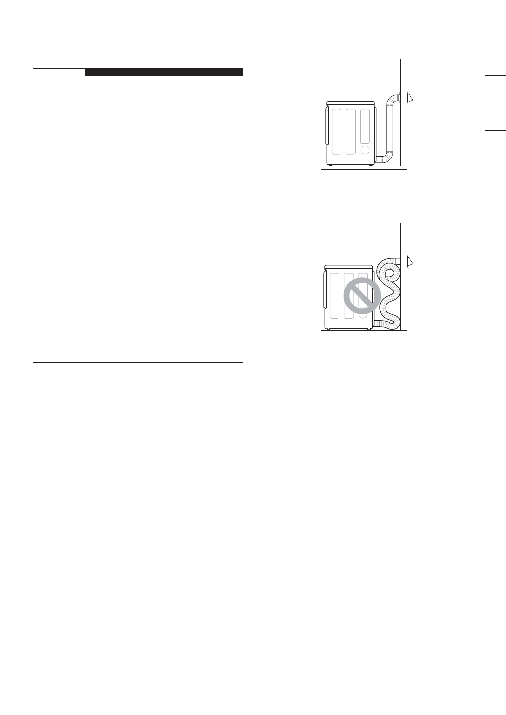
Routing and Connecting Ductwork
NOTE
Follow the guidelines below to maximize
drying performance and reduce lint buildup
and condensation in the ductwork. Ductwork
and fittings are NOT included and must be
purchased separately.
• Use 4-inch (10.2 cm) diameter rigid, semi-rigid
or flexible metal ductwork.
• The exhaust duct run should be as short as
possible.
• Use as few elbow joints as possible.
• The male end of each section of exhaust duct
must point away from the dryer.
• Use duct tape on all duct joints.
• Insulate ductwork that runs through unheated
areas in order to reduce condensation and lint
buildup on duct surfaces.
• Incorrect or inadequate exhaust systems
are not covered by the dryer warranty. Dryer
failures or service required because of such
exhaust systems will not be covered by the
dryer warranty.
Correct Venting
ENGLISH
Incorrect Venting
Page 20
INSTALLATION
20
Connecting Gas Dryers
WARNING
To reduce the risk of fire or explosion,
electric shock, property damage, injury to
persons, or death when using this appliance,
follow requirements including the following:
Electrical Requirements for Gas
Models Only
• Do not, under any circumstances, cut or remove
the third (ground) prong from the power cord.
• For personal safety, this dryer must be properly
grounded.
• This dryer must be plugged into a 120-VAC, 60-
Hz. grounded outlet protected by a 15-ampere
fuse or circuit breaker.
ELECTRIC SHOCK HAZARD
Failure to follow safety warnings could result
in serious injury
• This dryer is equipped with a three-prong
grounding plug for protection against shock
hazard and should be plugged directly into a
properly grounded three-prong receptacle. Do
not cut or remove the grounding prong from this
plug.
• Where a standard 2-prong wall outlet is
encountered, it is your personal responsibility
and obligation to have it replaced with a properly
grounded 3-prong wall outlet.
Gas Supply Requirements
• As shipped from the factory, this dryer is
configured for use with natural gas (NG). It can
be converted for use with propane (LP) gas.
Gas pressure must not exceed 8-inch (20.4 cm)
water column for NG, or 13-inch (33.1 cm) water
column for LP.
• A qualified service or gas company technician
must connect the dryer to the gas service.
• Isolate the dryer from the gas supply system by
closing its individual manual shutoff valve during
any pressure testing of the gas supply.
• Supply line requirements: Your laundry room
must have a rigid gas supply line to your dryer.
In the United States, an individual manual
shutoff valve MUST be installed within at least
6 ft. (1.8 m) of the dryer, in accordance with
the National Fuel Gas Code ANSI Z223.1 or
Canadian gas installation code CSA B149.1. A
1/8-inch NPT pipe plug must be installed.
• If using a rigid pipe, the rigid pipe should be
0.5-inch IPS. If acceptable under local codes
and ordinances and when acceptable to your
gas supplier, 3/8-inch approved tubing may be
used where lengths are less than 20 ft. (6.1
m). Larger tubing should be used for lengths in
excess of 20 ft. (6.1 m).
• To prevent contamination of the gas valve,
purge the gas supply of air and sediment before
connecting the gas supply to the dryer. Before
tightening the connection between the gas
supply and the dryer, purge remaining air until
the odor of gas is detected.
• DO NOT use an open flame to inspect for gas
leaks. Use a noncorrosive leak detection fluid.
• Use only a new AGA- or CSA-certified
gas supply line with flexible stainless steel
connectors.
• Use Teflon tape or a pipe-joint compound that
is insoluble in propane (LP) gas on all pipe
threads.
WARNING
• DO NOT attempt any disassembly of the
dryer; disassembly requires the attention and
tools of an authorized and qualified service
technician or company.
• Securely tighten all gas connections.
• Connect the dryer to the type of gas shown on
the nameplate.
Connecting the Gas Supply
• Installation and service must be performed by
a qualified installer, service agency, or the gas
supplier.
• Use only a new stainless steel flexible connector
and a new AGA-certified connector.
• A gas shutoff valve must be installed within 6 ft.
(1.8 m) of the dryer.
Page 21
INSTALLATION
21
• The dryer is configured for natural gas when
shipped from the factory. Make sure that the
dryer is equipped with the correct burner nozzle
for the type of gas being used (natural gas or
propane gas).
• If necessary, the correct nozzle (for the LP
nozzle kit, order part number 383EEL3002D)
should be installed by a qualified technician and
the change should be noted on the dryer.
• All connections must be in accordance with
local codes and regulations. Gas dryers MUST
exhaust to the outdoors.
NOTE
• In the Commonwealth of Massachusetts:
This product must be installed by a licensed
plumber or gas fitter. When using ball-type gas
shut off valves, they must be T-handle-type. A
flexible gas connector, when used, must not
exceed 3 feet.
This dryer is configured from the factory for natural
gas (NG). If the dryer is to be used with propane
(LP) gas, it must be converted by a qualified
service technician.
Check all pipe connections (both internal and
6
external) for gas leaks with a noncorrosive
leak-detection fluid.
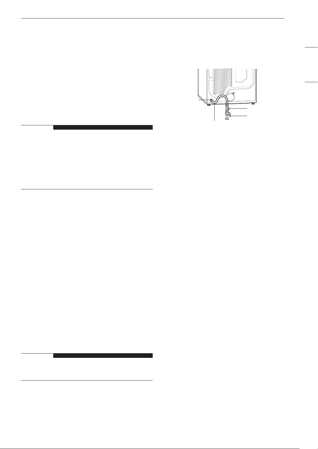
Proceed to Venting the Dryer.
7
3/8” NPT gas
Connection
AGA/CSA-Certified
Stainless Steel Flexible
Connector
1/8” NPT Pipe Plug
Gas Supply Shutoff
Valve
High-Altitude Installations
The BTU rating of this dryer is AGA-certified for
elevations below 10,000 feet.
If your gas dryer is being installed at an elevation
above 10,000 feet, it must be derated by a
qualified technician or gas supplier.
ENGLISH
Make sure that the gas supply to the
1
laundry room is turned OFF and the dryer
is unplugged. Confirm that the type of gas
available in your laundry room is appropriate
for the dryer.
Remove the shipping cap from the gas fitting
2
at the back of the dryer. Be careful not to
damage the threads of the gas connector
when removing the shipping cap.
Connect the dryer to your laundry room’s gas
3
supply using a new flexible stainless steel
connector with a 3/8-inch NPT fitting.
NOTE
• DO NOT use old connectors.
Securely tighten all connections between the
4
dryer and your laundry room’s gas supply.
Turn on your laundry room’s gas supply.
5
Page 22

INSTALLATION
22
Connecting Electric Dryers
WARNING
To reduce the risk of fire or explosion,
electric shock, property damage, injury to
persons, or death when using this appliance,
follow requirements including the following:
Electrical Requirements for Electric
Models Only
• The wiring and grounding must conform to
the latest edition of the National Electrical
Code, ANSI/NFPA 70 and all applicable
local regulations. Please contact a qualified
electrician to check your home’s wiring and
fuses to ensure that your home has adequate
electrical power to operate the dryer.
• This dryer must be connected to a grounded
metal, permanent wiring system, or an
equipment-grounding conductor must be run
with the circuit conductors and connected to the
equipment-grounding terminal or lead on the
dryer.
• The dryer has its own terminal block that must
be connected to a separate 240 VAC, 60-Hertz,
single-phase circuit, fused at 30 amperes (the
circuit must be fused on both sides of the line).
ELECTRICAL SERVICE FOR THE DRYER
SHOULD BE OF THE MAXIMUM RATE
VOLTAGE LISTED ON THE NAMEPLATE. DO
NOT CONNECT THE DRYER TO 110-, 115-,
OR 120-VOLT CIRCUIT.
• If the branch circuit to dryer is 15 ft. (4.5
m) or less in length, use UL (Underwriters
Laboratories) listed No.-10 AWG wire (copper
wire only), or as required by local codes. If
over 15 ft. (4.5 m), use UL-listed No.-8 AWG
wire (copper wire only), or as required by local
codes. Allow sufficient slack in wiring so the
dryer can be moved from its normal location
when necessary.
• The power cord (pigtail) connection between the
wall receptacle and the dryer terminal block IS
NOT supplied with the dryer. Type of pigtail and
gauge of wire must conform to local codes and
with instructions on the following pages.
• A 4-wire connection is required for all mobile
and manufactured home installations, as well
as all new construction after January 1, 1996.
A 4-wire connection must be used where local
codes do not permit grounding through the
neutral wire.
• Do not modify the plug and internal wire
provided with the dryer.
• The dryer should be connected to a 4-hole
outlet.
• If the plug does not fit the outlet, a proper
outlet will need to be installed by a qualified
electrician.
• Connect the power cord to the terminal block.
Each colored wire should be connected to
the same color screw. Wire color indicated on
manual is connected to the same color screw in
the block.
• Grounding through the neutral conductor
is prohibited for: (1) new branch-circuit
installations, (2) mobile homes, (3) recreational
vehicles, and (4) areas where local codes
prohibit grounding through the neutral
conductor.
• This dryer is supplied with the neutral wire
grounded. This white ground wire MUST BE
MOVED to the neutral terminal when a 4-wire
cord is to be used, or where grounding through
the neutral conductor is prohibited.
NOTE
• For electrical requirements for mobile or
manufactured homes, see Special Electrical
Requirements.
Page 23
INSTALLATION
23
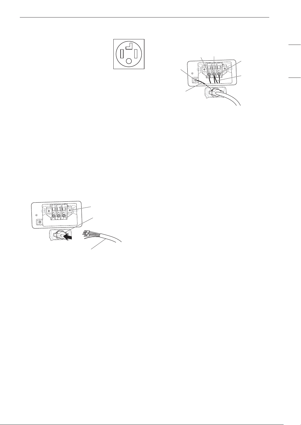
Four-Wire Power Cord
• A 4-wire connection is required
for all mobile and manufactured
home installations, as well as all
new construction after January 1,
1996.
• A UL-listed strain relief is required.
• Use a 30-amp, 240-volt, 4-wire,
UL-listed power cord with #10
AWG-minimum copper conductor
and closed loop or forked
terminals with upturned ends.
Remove the terminal block access cover on
1
the upper back of the dryer.
Install a UL-listed strain relief into the power
2
cord through-hole.
Thread a 30-amp, 240-volt, 4-wire, UL-listed
3
power cord with #10 AWG-minimum copper
conductor through the strain relief.
Tighten all screws securely.
8
Reinstall the terminal block access cover.
9
Hot (Black) Neutral (White)
Hot (Red)
Ground
Screw
Power Cord
Ground Wire
White Wire
moved from
Ground Screw
ENGLISH
Terminal Block
UL-Listed Strain
Relief
UL-Listed 4-Wire Power Cord
Transfer the dryer’s ground wire from behind
4
the green ground screw to the center screw of
the terminal block.
Attach the two hot leads of the power cord to
5
the outer terminal block screws.
Attach the white neutral wire to the center
6
screw of the terminal block.
Attach the power cord ground wire to the
7
green ground screw.
Page 24
INSTALLATION
24
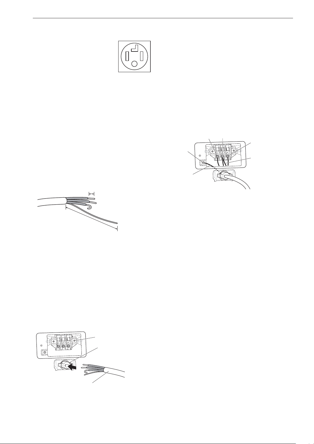
Four-Wire Direct Wire
• A 4-wire connection is required
for all mobile and manufactured
home installations, as well as all
new construction after January 1,
1996.
• A UL-listed strain relief is required.
• Use UL-listed 4-wire #10 AWG-
minimum copper conductor
cable. Allow at least 5 ft. (1.5 m)
of wire to allow for removal and
reinstallation of the dryer.
Remove 5-inch (12.7 cm) of the outer covering
1
from the wire. Remove 5-inch of insulation
from the ground wire. Cut off approximately
1.5-inch (3.8 cm) from the other three wires
and strip 1 inch (2.5 cm) insulation from each
wire. Bend the ends of the three shorter wires
into a hook shape.
1” (2.5 cm)
Attach the two hot leads of the power cord to
6
the outer terminal block screws.
Attach the white neutral wire to the center
7
screw of the terminal block.
Attach the power cord ground wire to the
8
green ground screw.
Tighten all screws securely.
9
Reinstall the terminal block access cover.
10
Hot (Black) Neutral (White)
Ground
Screw
Power Cord
Ground Wire
Hot (Red)
White Wire
moved from
Ground Screw
Ground Wire
5” (12.7 cm)
Remove the terminal block access cover on
2
the upper back of the dryer.
Install a UL-listed strain relief into the power
3
cord through-hole.
Thread the 4-wire #10 AWG-minimum copper
4
power cable prepared in step 1 through the
strain relief.
Terminal Block
UL-Listed
Strain Relief
UL-Listed 4-Wire Power Cord
Transfer the dryer’s ground wire from behind
5
the green ground screw to the center screw of
the terminal block.
Page 25
INSTALLATION
25
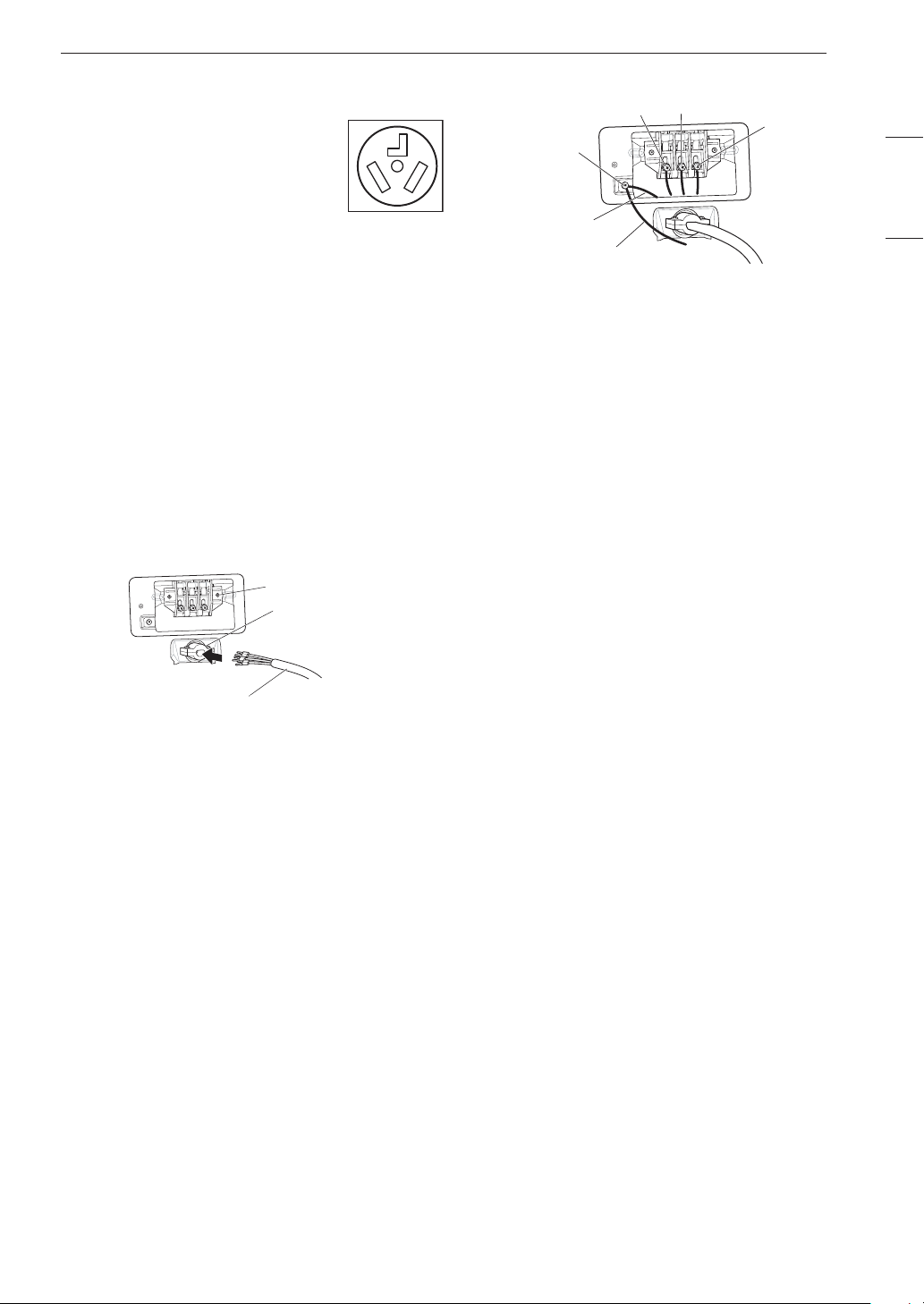
Three-Wire Power Cord
• A 3-wire connection is NOT
permitted on new construction
after January 1, 1996.
• A UL-listed strain relief is required.
• Use a 30-amp, 240-volt, 3-wire,
UL-listed power cord with #10
AWG-minimum copper conductor
and closed loop or forked
terminals with upturned ends.
Remove the terminal block access cover on
1
the upper back of the dryer.
Install a UL-listed strain relief into the power
2
cord through-hole.
Thread a 30-amp, 240-volt, 3-wire, UL-listed
3
power cord with #10 AWG-minimum copper
conductor through the strain relief.
Terminal Block
UL-Listed
Strain Relief
Reinstall the terminal block access cover.
8
Hot (Black) Neutral (White)
Ground
Screw
White Wire
from Dryer
harness
External Ground Wire (If
required by local codes)
Hot (Red)
ENGLISH
UL-Listed 3-Wire Power Cord
Attach the two hot leads (black and red) of the
4
power cord to the outer terminal block screws.
Attach the neutral (white) wire to the center
5
terminal block screw.
Connect the external ground (if required by
6
local codes) to the green ground screw.
Tighten all screws securely.
7
Page 26
INSTALLATION
26
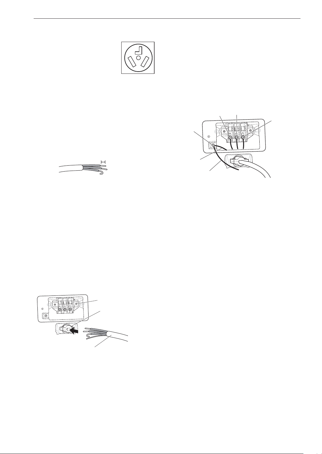
Three-Wire Direct Wire
• A 3-wire connection is NOT
permitted on new construction
after January 1, 1996.
• A UL-listed strain relief is required.
• Use UL-listed 3-wire, #10 AWG-
minimum copper conductor
cable. Allow at least 5 ft. (1.5 m)
length to allow for removal and
installation of dryer.
Remove 3.5-inch (8.9 cm) of the outer
1
covering from the wire. Strip 1 inch (2.5 cm)
insulation from each wire. Bend the ends of
the three wires into a hook shape.
1” (2.5 cm)
Attach the neutral (white) wire to the center
6
terminal block screw.
Connect the external ground (if required by
7
local codes) to the green ground screw.
Tighten all screws securely.
8
Reinstall the terminal block access cover.
9
Hot (Black)
Ground
Screw
White Wire
from Dryer
harness
External Ground Wire (If
required by local codes)
Neutral (White)
Hot (Red)
Remove the terminal block access cover on
2
the upper back of the dryer.
Install a UL-listed strain relief into the power
3
cord through-hole.
Thread the 3-wire, #10 AWG-minimum copper
4
conductor power cable prepared in step 1
through the strain relief.
Terminal Block
UL-Listed
Strain Relief
UL-Listed 3-Wire Power Cord
Attach the two hot leads (black and red) of the
5
power cord to the outer terminal block screws.
Page 27

INSTALLATION
27
Special Electrical Requirements
(For Mobile or Manufactured Homes)
• Any installation in a manufactured or mobile
home must comply with the Manufactured Home
Construction and Safety Standards Title 24
CFR, Part 3280 or Standard CAN/ CSA Z240
MH and local codes and ordinances. If you are
uncertain whether your proposed installation
will comply with these standards, please contact
a service and installation professional for
assistance.
• A 4-wire connection is required for all mobile
and manufactured home installations, as well as
all new construction after January 1, 1996.
• A gas dryer must be permanently attached to
the floor.
• The electrical connection for an electric dryer
must be a 4-wire connection. More detailed
information concerning the electrical connection
is provided in the section Connecting Electric
Dryers.
• To reduce the risk of combustion and fire, the
dryer must be vented to the outside.
• DO NOT vent the dryer under a manufactured
home or mobile home.
• Electric dryers may be vented to the outside
using the back, left, right, or bottom panel.
• Gas dryers may be vented to the outside using
the back, left, or bottom panel. Gas dryers may
not be vented to the outside using the right side
panel because of the burner housing.
• The dryer exhaust duct must be affixed securely
to the manufactured or mobile home structure,
and the exhaust duct must be made of a
material that will resist fire and combustion. It is
recommended that you use a rigid, semi-rigid or
flexible metal duct.
• DO NOT connect the dryer exhaust duct to any
other duct, vent, chimney, or other exhaust duct.
• Make sure the dryer has adequate access to
outside fresh air to ensure proper operation. The
opening for outside fresh air must be at least 25
sq. in (163 cm²).
• It is important that the clearance of the duct
from any combustible construction be at least 2
inches (5 cm), and when venting the dryer to the
outdoors, the dryer should be installed with a
clearance of at least 1 inch (2.5 cm) at the sides
and back of the dryer.
• Please be aware that venting materials are
not supplied with the dryer. You must obtain
the venting materials necessary for proper
installation.
Final Installation Check
Once you have completed the installation of the
dryer and it is in its final location, confirm proper
operation with the following tests and Installation
Test (Duct Check).
Testing Dryer Heating
GAS MODELS
Close the dryer door and press the Power button
to turn the dryer on. Press the Time Dry and Start/
Pause buttons to start the test. When the dryer
starts, the igniter should ignite the main burner.
NOTE
• If all air is not purged from the gas line, the
gas igniter may turn off before the main
burner ignites. If this happens, the igniter will
reattempt gas ignition after approximately two
minutes.
ELECTRIC MODELS
Close the dryer door and press the Power button
to turn the dryer on. Press the Time Dry and Start/
Pause buttons to start the test. The exhaust air
should be warm after the dryer has been operating
for 3 minutes.
Checking Airflow
Effective dryer operation requires proper airflow.
The adequacy of the airflow can be measured
by evaluating the static pressure. Static
pressure in the exhaust duct can be measured
with a manometer, placed on the exhaust duct
approximately 2 ft. (60.9 cm) from the dryer. Static
pressure in the exhaust duct should not exceed
0.6 inch (1.5 cm). The dryer should be checked
while the dryer is running with no load.
ENGLISH
Page 28
INSTALLATION
LED turned on:
RESTRICTED
28
Checking Levelness
Once the dryer is in its final location, recheck the
dryer to be sure it is level. Make sure it is level
front to back and side to side, and that all four
leveling feet are in firm contact with the floor.
Installation Test (Duct Check)
Once you have completed the installation of the
dryer, use this test to make sure the condition
of the exhaust system is adequate for proper
operation of the dryer. This test should be
performed to alert you to any serious problems in
the exhaust system of your home.
• Your dryer features Flow Sense™, an innovative
sensing system that automatically detects
blockages and restrictions in dryer ductwork.
Keeping ductwork clean of lint buildup and free
of restrictions allows clothes to dry faster and
reduces energy use.
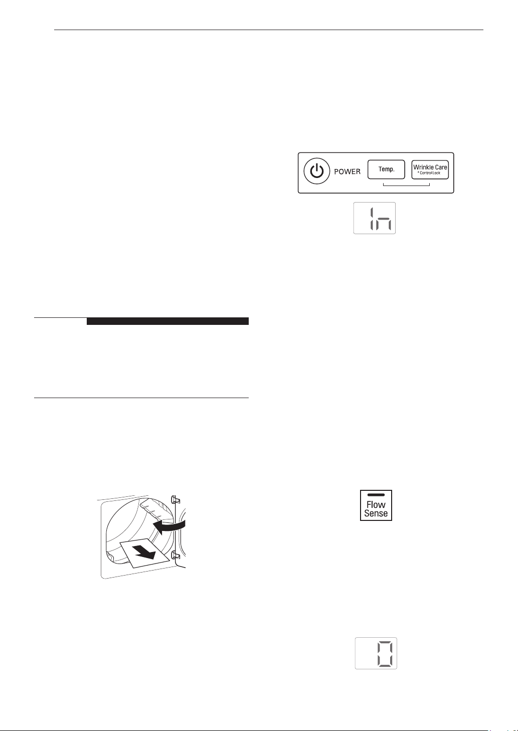
NOTE
Press and hold the Signal and Temp.
2
buttons and then press the Power button.
(On models with a glass touch control panel,
press the Power button then IMMEDIATELY
press and hold the Temp. and Wrinkle Care
buttons.) This button sequence activates the
installation test. The code 1N will display if the
activation is successful.
Press the START/PAUSE button.
3
The dryer will start the test, which will last
a few minutes. The heat will be turned on
and the temperatures in the drum will be
measured.
• The dryer should be cool before starting
this test. If the dryer was warmed up during
installation, run the Air Dry cycle for a few
minutes to reduce the interior temperature.
Activating the Installation Test
Remove the literature, and then close the
1
door.
Do not load anything in the drum for this test,
as it may affect the accuracy of the results.
Check the display for results.
4
During the test cycle, monitor the Flow
Sense™ display on the control panel. If
the Flow Sense™ LED has not turned on
when the cycle ends, the exhaust system is
adequate. If the exhaust system is severely
restricted, the Flow Sense™ LED will turn on.
Other problems may also be shown with error
codes. See the chart on the next page for error
code details and solutions.
End of cycle.
5
At the end of the test cycle, O will display. The
test cycle will end and the dryer will shut off
automatically after a short delay.
Page 29
INSTALLATION
29
Check the Duct Condition
If the Flow Sense™ LED is turned on, check
the exhaust system for restrictions and damage.
Repair or replace the exhaust system as needed.
NOTE
• When the dryer is first installed, this test
should be performed to alert you to any
existing problems with the exhaust duct in
your home. However, since the test performed
during normal operation provides more
accurate information on the condition of the
exhaust duct than the installation test, the
number of bars displayed during the two tests
may not be the same.
• Do not interrupt the test cycle, as this could
result in inaccurate results.
• Even if no bars are displayed during the test
cycle, some restrictions may still be present
in the exhaust system. Refer to the Venting
the Dryer section of this manual for complete
exhaust system and venting requirements.
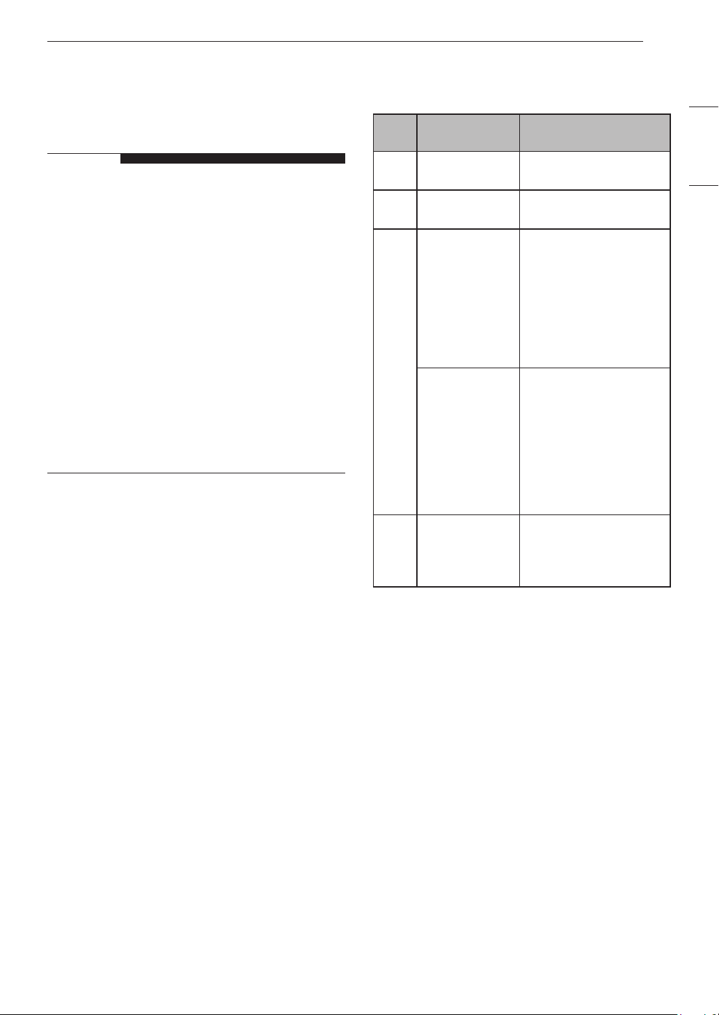
Error Codes
Check the error code before you call for service.
Error
Code
tE1 or
tE2
HS
PS,
PF, or
nP
gAS
Possible
Causes
Temperature
sensor failure.
Humidity sensor
failure.
Electric dryer
power cord is
not connected
correctly, or
house power
supply is
incorrect.
House fuse is
blown, circuit
breaker has
tripped, or
power outage
has occurred.
Gas supply or
service turned
off. (Gas Model
only.)
Solutions
Turn off the dryer and
call for service.
Turn off the dryer and
call for service.
Check the power supply
or the connection of
the power cord to the
terminal block. Refer to
the Connecting Electric
Dryers section of this
manual for complete
instructions.
Reset circuit breaker
or replace fuse. Do
not increase the fuse
capacity.
If the problem is a
circuit overload, have it
corrected by a qualified
electrician.
Confirm that house gas
shutoff and the dryer
gas shutoff are both
fully open.
ENGLISH
Page 30
INSTALLATION
30
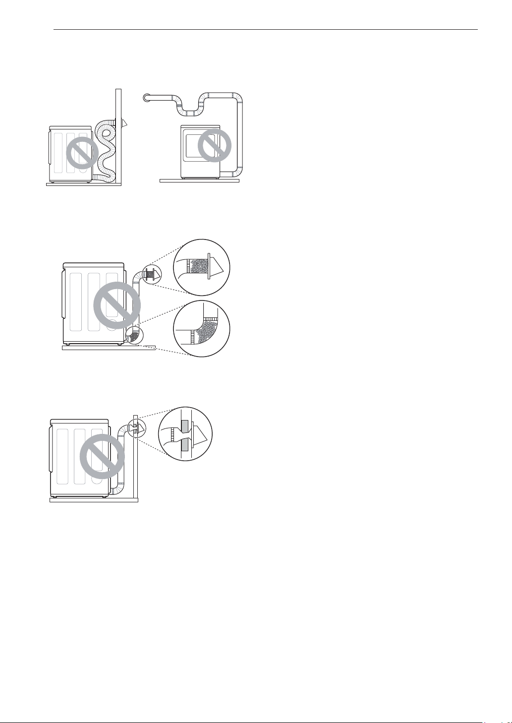
Restricted or Blocked Airflow
Avoid long runs or runs with multiple elbows or
bends.
Excess or crushed
transition duct
Check for blockages and lint buildup.
Lint buildup or blockage
Make sure the ductwork is not crushed or
restricted.
Too many elbows or
exhaust too long
Crushed or damaged
exhaust
Page 31

OPERATION
OPERATION
31
WARNING
• To reduce the risk of fire, electric shock, or injury to persons, read the SAFETY INSTRUCTIONS
before operating this appliance.
Using the Dryer
Clean the Lint Filter
1
If the lint filter has not already been cleaned, lift out the filter and remove
the lint from the last load. This will help ensure the fastest and most efficient
drying performance. Make sure to reinstall the filter, pressing down until it
clicks firmly into place.
Load the Dryer
2
Load the dryer with the wet laundry from the washer. If the load is extra large,
you may need to divide it into smaller loads for proper performance and fabric
care.
Turn on the Dryer
3
Press the Power button to turn on the dryer. The cycle LEDs will illuminate
and a chime will sound.
ENGLISH
Select a Cycle
4
Turn the cycle selector knob in either direction until the LED for the desired
cycle is on. The preset temperature, dry level, and option settings for that
cycle will be shown. Default settings for the selected cycle can now be
changed if desired. Refer to the Cycle Setting and Options page for details.
NOTE
• Not all options or modifiers are available on all cycles. Refer to
the Cycle Guide page for default settings and available options.
A different chime will sound and the LED will not come on if the
selection is not available.
Begin Cycle
5
Press the Start/Pause button to begin the cycle. The cycle can be paused at
any time either by opening the door or by pressing the Start/Pause button.
If the cycle is not restarted within 60 minutes of being paused, the dryer will
shut off and the settings will be lost.
End of Cycle
6
When the cycle is finished, the chime will sound. Immediately remove your
clothing from the dryer to reduce wrinkling. If Wrinkle Care is selected, the
dryer will tumble briefly every few minutes to help prevent wrinkles from
setting in the clothes.
Page 32

OPERATION
32
Check the Lint Filter Before Every Load
Always make sure the lint filter is clean before
starting a new load; a clogged lint filter will
increase drying time. To clean, pull the lint filter
straight up and roll any lint off the filter with your
fingers. Push the lint filter firmly back into place.
See Regular Cleaning for more information.
Always ensure the lint filter is properly installed
before running the dryer. Running the dryer with
a loose or missing lint filter will damage the dryer
and articles in the dryer.
Lint Filter
Grouping Similar Items
For best results, sort clothes into loads that can be
dried with the same drying cycle.
Different fabrics have different care requirements,
and some fabrics will dry more quickly than others.
Loading the Dryer
WARNING
• Check all pockets to make sure that they are
empty. Items such as clips, pens, coins, and
keys can damage both the dryer and your
clothes. Flammable objects such as lighters or
matches could ignite, causing a fire.
• Never dry clothes that have been exposed to
oil, gasoline, or other flammable substances.
Washing clothes will not completely remove oil
residues.
Sorting Laundry
Fabric Care Labels
Many articles of clothing include a fabric care
label. Using the chart below, adjust the cycle
and option selections to care for your clothing
according to the manufacturer’s recommendations.
Tumble dry
Dry Gentle/delicate
Normal
Permanent
Press/ wrinkle
resistant
Heat setting
High Low
Do not tumble
dry
Do not dry (used
with do not wash)
NOTE
Loading Tips
• Combine large and small items in the same
load.
• Damp clothes will expand as they dry. Do not
overload the dryer; clothes require room to
tumble and dry properly.
• Close zippers, hooks, and drawstrings to
prevent these items from snagging or tangling
on other clothes.
Medium No heat/air
Page 33

Control Panel
OPERATION
33
Non-Steam Models (DLE3400*, DLG3401*)
Power Button
a
Press the button to turn the dryer ON. Press
again to turn the dryer OFF.
NOTE
• Pressing the Power button during a
cycle will cancel that cycle and any load
settings will be lost.
Cycle Selector Knob
b
Turn this knob to select the desired cycle.
Once the desired cycle has been selected,
the standard presets will be shown in the
display. On Manual Dry cycles, these settings
can be adjusted using the cycle modifier
buttons anytime before starting the cycle.
Start/Pause Button
c
Press this button to start the selected cycle. If
the dryer is running, use this button to pause
the cycle without losing the current settings.
NOTE
Cycle Modifier Buttons
d
Use these buttons to select the desired cycle
settings for the selected cycle. The current
settings are shown in the display. Press the
button for that option to view and select other
settings.
Cycle Option Buttons
e
Press each of these buttons to select
additional cycle options. Press and hold any
button marked with an asterisk for 3 seconds
to activate a special function.
More Time/Less Time Buttons
f
Use these buttons with the Time Dry and
other Manual Dry cycles to adjust the drying
time. Press the More Time button to increase
the selected manual cycle time by 1 minute;
press the Less Time button to decrease the
cycle time by 1 minute.
Time and Status Display
g
The display shows the settings, estimated
time remaining, options, and status
messages for the dryer.
ENGLISH
• If you do not press the Start/Pause
button to resume a cycle within 60
minutes, the dryer turns off automatically
and all cycle settings are lost.
Page 34

OPERATION
34
Clean Filter Reminder
h
The Clean Filter LED is lit when the dryer is
turned on as a reminder to clean the filter. It
turns off when the START/PAUSE button is
pressed.
Flow Sense Duct Blockage Sensing
i
System Indicator
The Flow Sense™ duct blockage sensing
system detects and alerts you to blockages
in the ductwork that reduce exhaust flow
from the dryer. Maintaining a clean exhaust
system improves operating efficiency and
helps minimize service calls, saving you
money.
Control Lock Indicator
j
When Control Lock is set, the Control
Lock indicator appears and all buttons are
disabled except the POWER button. This
prevents children from changing settings
while the dryer is operating.
Damp Dry Signal Indicator
k
The dryer will signal when the load is
approximately 80% dry. This allows you to
remove faster-drying lightweight items or
items that you would like to iron or hang
while they are still slightly damp.
Estimated Time Remaining
l
This display shows the estimated time
remaining for Sensor Dry cycles or the actual
time remaining for Time Dry or Manual Dry
cycles.
NOTE
• The cycle time on Sensor Dry cycles may
fluctuate as the dryer recalculates drying
time for optimal results.
Cycle Completion Indicator
m
This portion of the display shows which stage
of the drying cycle is currently underway (Dry
or Cool).
Page 35

OPERATION
35
Cycle Guide
Sensor Dry Cycles
Sensor Dry cycles utilize LG’s unique dual sensor
system to detect and compare the moisture level
in clothes and in the air and adjust the drying
time as needed to ensure superior results. The
dryer automatically sets the dryness level and
temperature at the recommended setting for each
cycle. The estimated time remaining will be shown
in the display.
NOTE
• To protect your garments not every dryness
level, temperature, or option is available with
every cycle. See the Cycle Guide for details.
Non-Steam Models (DLE3400*, DLG3401*)
Manual Dry Cycles
Use Manual Dry cycles to select a specific amount
of drying time and a drying temperature. When
a Manual Dry cycle is selected, the Estimated
Time Remaining display shows the actual time
remaining in your cycle. You can change the actual
time in the cycle by pressing the More Time or
Less Time buttons.
NOTE
• The Energy Saver option is turned on by
default in the Normal Cycle. Turn off the
Energy Saver option for a faster Normal cycle
which begins with heated drying. To turn the
Energy Saver default off, press and hold the
Energy Saver button. ON or OFF appears in
the display.
= default setting
# = allowable option
ENGLISH
Cycle Fabric Type
Normal*
Heavy Duty
Bedding
Towels
Perm. Press
Delicates
Speed Dry
Air Dry
Work clothes,
corduroys, etc.
Jeans, heavyweight
Comforters, Pillows,
Shirts
Denims, towels, heavy
cottons
Permanent press,
synthetic items
Lingerie, sheets,
blouses
For small loads with
short drying times
For items that require
heat-free drying such
as plastics or rubber
items
* = Energy Saver on by default
Dry
Level
SENSOR DRY
Normal
Adj.
Normal
Adj.
Normal
Adj.
Normal
Adj.
Normal
Adj.
Normal
Adj.
MANUAL DRY
Off
Off No Heat ●
Temp. Wrinkle Care
Medium ● ●
High ● ●
Medium
Medium ● ●
Medium ● ●
Low ● ●
High
Adj.
Damp Dry
Signal
●
Page 36

OPERATION
36
Cycle Modifier Buttons
Sensor Dry cycles have preset settings that are
selected automatically. Manual Dry cycles have
default settings, but you may also customize the
settings using the cycle modifier buttons. Press
the button for that option to view and select other
settings.
Dry Level
Use this button to select the level of dryness for
the cycle. Press the Dry Level button repeatedly
to scroll through available settings.
• This option is only available with Sensor Dry
cycles.
• The dryer will automatically adjust the cycle
time. Selecting More or Very will increase the
cycle time, while Less or Damp will decrease
the cycle time.
• Use a Less or Damp setting for items that you
wish to iron.
Temp.
Use this button to adjust the temperature setting.
This allows precise care of fabrics and garments.
Press the Temp. button repeatedly to scroll
through available settings.
Option Buttons
The dryer features several additional cycle options
to customize cycles to meet individual needs.
Certain option buttons also feature a special
function that can be activated by pressing and
holding that option button for 3 seconds.
Adding Cycle Options to a Cycle
Turn on the dryer and turn the Cycle selector
1
knob to select the desired cycle.
Use the cycle modifier buttons to adjust the
2
settings for that cycle.
Press the cycle option button(s) to add the
3
desired options. A confirmation message is
shown in the display.
Press the Start/Pause button to start the
4
cycle. The dryer starts automatically.
Wrinkle Care
Selecting this option will tumble the load
periodically for up to 3 hours after the selected
cycle, or until the door is opened. This is helpful
in preventing wrinkles when you are unable to
remove items from the dryer immediately.
Time Dry
Use this button to manually select the drying time,
from 20 to 60 minutes, in 20-minute increments.
Use this for small loads or to remove wrinkles.
Use the More Time/Less Time buttons to add or
reduce the drying time in 1-minute increments.
Energy Saver
This option helps to reduce the energy
consumption of the Normal Cycle, depending on
the load size. When the Energy Saver option is
selected, the cycle begins with an air dry section
and the drying time is increased.
Turn off the Energy Saver option for a faster
Normal cycle which begins with heated drying. To
turn the Energy Saver default off, press and hold
the Energy Saver button. ON or OFF appears in
the display.
Page 37

OPERATION
37
Special Functions
Some cycle option buttons also activate secondary
functions. These special functions are marked with
an asterisk (*). Press and hold the option button
marked with the special function to activate it.
Control Lock
Use this option to prevent unwanted use of the
dryer or to keep cycle settings from being changed
while the dryer is operating.
Activating the Control Lock Function
Press and hold the Wrinkle Care button for 3
seconds.
The Control Lock icon will be shown in the display,
and all controls will be disabled except the Power
button.
Deactivating the Control Lock Function
Press and hold the Wrinkle Care button for 3
seconds.
Default On/Off
This option allows the Energy Saver settings to
be changed. To run a Normal cycle without the
Energy Saver option, press and hold the Energy
Saver button for three seconds. ON or OFF
appears in the display.
ENGLISH
Once set, Control Lock remains active until it is
manually deactivated. Control Lock must be turned
off to run another cycle.
Damp Dry Signal
When this option is selected, the dryer signals
when the load is approximately 80% dry. This
allows you to remove faster-drying lightweight
items or items that you would like to iron or hang
while they are still slightly damp.
SIGNAL
Press and hold the Dry Level button for 3 seconds
to adjust the volume of the signal. Press and hold
the button repeatedly to adjust the volume of the
melody. When no signal is heard, the signal is off.
The volume settings are ON – OFF. The signal
volume can be adjusted at any time as long as the
dryer is turned ON.
Page 38

SMART FUNCTIONS
38
SMART FUNCTIONS
LG ThinQ Application
Installing the LG ThinQ Application
Search for the LG ThinQ application from the
Google Play Store or Apple App Store on a
smartphone. Follow instructions to download and
install the application.
LG ThinQ Application Features
• Smart Diagnosis™
− This function provides useful information
for diagnosing and solving issues with the
appliance based on the pattern of use.
Smart Diagnosis™ Feature
This feature is only available on models with the c
or d logo.
Use this feature to help you diagnose and solve
problems with your appliance.
Press the Power button to turn on the
1
appliance.
• Do not press any other buttons.
Hold the mouthpiece of your phone in front of
2
the c or d logo.
Max.
10 mm
Press and hold the Temp. button for 3
3
seconds or longer while continuing to hold
your phone to the logo.
Keep the phone in place untill the tone
4
transmission has finished. The display will
count down the time. Once the countdown
is over and the tones have stopped, the
diagnosis will be displayed in the application.
NOTE
NOTE
• For reasons not attributable to LGE’s
negligence, the service may not operate due
to external factors such as, but not limited to,
Wi-Fi unavailability, Wi-Fi disconnection, local
app store policy, or app unavailability.
• The feature may be subject to change without
prior notice and may have a different form
depending on where you are located.
Using Audible Diagnosis to
Diagnose Issues
Follow the instructions below to use the audible
diagnosis method.
• Launch the LG ThinQ application and select the
Smart Diagnosis feature in the menu. Follow
the instructions for audible diagnosis provided in
the LG ThinQ application.
• For best results, do not move the phone while
the tones are being transmitted.
Page 39

MAINTENANCE
39
MAINTENANCE
Regular Cleaning
WARNING
• Unplug the dryer before cleaning.
• Never use harsh chemicals, abrasive
cleaners, or solvents to clean the washer.
They will damage the finish.
Cleaning the Exterior
Proper care of your dryer can extend its life.
The outside of the machine can be cleaned with
warm water and a mild, nonabrasive household
detergent. Immediately wipe off any spills with a
soft, damp cloth.
NOTE
Cleaning Around and Under the
Dryer
Vacuum lint and dust from around the dryer and
underneath it regularly. Vent ductwork should be
checked for lint buildup and cleaned at least once
per year. If any noticeable reduction in airflow or
drying performance occurs, immediately check
ductwork for obstructions and blockages.
Maintaining Ductwork
Vent ductwork should be checked for lint buildup
once per month and cleaned at least once per
year. If any noticeable reduction in airflow or drying
performance occurs, immediately check ductwork
for obstructions and blockages. Contact a qualified
technician or service provider.
Cleaning the Lint Filter
Always clean the lint from the filter after every
cycle.
ENGLISH
• Do not use methylated spirits, solvents, or
similar products.
• Never use steel wool or abrasive cleansers;
they can damage the surface.
Cleaning the Interior
Wipe around the door opening and seal with a
soft, damp cloth to prevent lint and dust buildup
that could damage the door seal.
Clean the window with a soft cloth dampened with
warm water and a mild, nonabrasive household
detergent, then wipe dry.
The stainless steel drum can be cleaned with
a conventional stainless steel cleaner, used
according to the manufacturer’s specifications.
Never use steel wool or abrasive cleansers; they
may scratch or damage the surface.
Lint Filter
To clean the lint filter, open the dryer door and pull
the lint filter straight up. Then:
For everyday cleaning, roll any lint off the filter
1
with your fingers, or
Vacuum the lint filter.
2
Page 40

MAINTENANCE
40
If the lint filter has become very dirty or
3
clogged with fabric softener, wash the lint
filter in warm, soapy water and allow it to dry
thoroughly before reinstalling.
NOTE
• NEVER operate the dryer without the lint filter
in place.
Page 41

TROUBLESHOOTING
TROUBLESHOOTING
41
FAQs: Frequently Asked Questions
Q: When I press a button, why does my dryer beep and then nothing happens?
A: The Control Lock feature is turned on. To turn off Control Lock, turn the dryer on, then press and hold
the button that has *Control Lock on or under it for 3 seconds.
Q: Why does my dryer take so long to dry clothes?
A: Proper airflow is critical to the efficient operation of clothes dryers. A lint filter which is full of lint or
clogged with fabric softener sheet residue can reduce the airflow to the point that the time required
to dry clothing will be greatly increased. Another factor affecting dry time is your home exhaust
system. An exhaust system which is dirty and clogged with lint, or is excessively long, needs to be
professionally cleaned or repaired.
Q: Why does my dryer start by itself every few minutes?
A: This is how the Wrinkle Care feature works. The dryer runs briefly every few minutes for up to 3
hours after the cycle finishes. This feature is designed to help prevent wrinkles from setting in when
the dryer is not unloaded immediately after the cycle is finished.
User Support Videos
ENGLISH
For further assistance, there are videos and tutorials available
through the LG.com website.
On the lg.com/us home page, click on the Support
1
menu tab to bring up the menu selections. Select Video
Tutorials.
Type Dryer in the search box on the new page and click
2
the Search button.
Scan this QR code to quickly access the
video search page on the LG website.
Page 42

TROUBLESHOOTING
42
Before Calling for Service
This dryer is equipped with an automatic error-monitoring system to detect and diagnose problems at an
early stage. If the dryer does not function properly or does not function at all, check the following before
you call for service.
Operation
Problem Possible Causes & Solution
The Flow Sense™
indicator remains
active after clearing
the restriction in
the venting.
Dryer will not turn
on
Dryer does not heat
Clothes take too
long to dry
Display show error
code nP
After clearing the restriction, the Flow Sense™ system requires multiple,
consecutive cycles to determine that the performance value has improved
before the Flow Sense™ indicator is reset.
• If the Flow Sense™ indicator remains active for more than five cycles after the
restriction has been cleared, call for service.
Power cord is not properly plugged in.
• Make sure that the plug is securely plugged into a grounded outlet matching the
dryer’s rating plate.
House fuse is blown, circuit breaker has tripped, or power outage has
occurred.
• Reset circuit breaker or replace fuse. Do not increase fuse capacity. If the
problem is a circuit overload, have it corrected by a qualified electrician.
House fuse is blown, circuit breaker has tripped, or power outage has
occurred.
• Reset circuit breaker or replace fuse. Do not increase fuse capacity. If the
problem is a circuit overload, have it corrected by a qualified electrician.
• NOTE: Due to the design of electric dryers, it is possible for a circuit problem to
allow an electric dryer to run without heat.
Gas supply or service is turned off.
• Confirm that the house gas shutoff and the dryer gas shutoff valves are both
fully open. Even if gas is not supplied to the dryer, it will run and no error codes
will display. Verify that other gas appliances in the home are working normally.
ENERGY SAVER option selected (on some models)
• If using the Normal cycle, deselect the ENERGY SAVER option. The Energy
Saver option is selected by default. This option reduces energy use by adding
an air dry section to the beginning of the cycle. It is normal to feel no heat at the
beginning of the cycle while in ENERGY SAVER mode.
Exhaust ducts are blocked, dirty, or duct run is too long.
• Confirm that the exhaust duct is properly configured and free of debris, lint, and
obstructions. Make sure that outside wall dampers can open properly and are
not blocked, jammed, or damaged.
Load is not properly sorted.
• Separate heavy items from lightweight items. Larger and heavier items take
longer to dry. Light items in a load with heavy items can fool the sensor
because the light items dry faster.
Electric dryer power cord is not connected correctly, or house power supply
is incorrect.
• Check the power supply or the connection of the power cord to the terminal
block.
Page 43

TROUBLESHOOTING
Problem Possible Causes & Solution
43
Display show error
code gAS
Clothes take too
long to dry
Drying time is not
consistent
Gas supply or service turned off (gas models only).
• Confirm that house gas shutoff and the dryer gas shutoff are both fully open.
Large load of heavy fabrics.
• Heavy fabrics take longer to dry because they tend to retain more moisture.
To help reduce and maintain more consistent drying times for large and heavy
fabrics, separate these items into smaller loads of a consistent size.
Dryer controls are not set properly.
• Use the appropriate control settings for the type of load you are drying. Some
loads may require an adjustment of the dry level setting for proper drying.
Lint filter needs to be cleaned.
• Remove the lint from the filter before every load. With the lint removed, hold the
filter up to a light to see if it is dirty or clogged. With some loads that produce
high amounts of lint, such as new bath towels, it may be necessary to pause
the cycle and clean the filter during the cycle.
House fuse is blown, circuit breaker has tripped, or power outage has
occurred.
• Reset circuit breaker or replace fuse. Do not increase fuse capacity. If the
problem is a circuit overload, have it corrected by a qualified electrician.
• NOTE: Due to the design of electric dryers, it is possible for a circuit problem to
allow an electric dryer to run without heat.
Dryer is overloaded.
• Divide extra large loads into smaller loads for better drying performance and
efficiency.
Dryer is underloaded.
• If you are drying a very small load, add a few extra items to ensure proper
tumbling action. If the load is very small and you are using SENSOR DRY
cycles, the electronic control cannot properly sense the dryness of the load and
may shut off too soon. Use TIME DRY or add some extra wet clothes to the
load.
ENERGY SAVER option selected (on some models)
• If using the Normal cycle, deselect the ENERGY SAVER option. This option
reduces energy use by adding an air dry section to the beginning of the cycle.
Heat settings, load size, or dampness of clothing is not consistent.
• The drying time for a load will vary depending on the type of heat used (electric,
natural gas, or LP gas), the size of the load, the type of fabrics, the wetness
of the clothes, and the condition of the exhaust duct and lint filter. Even an
unbalanced load in the washer can cause poor spinning, resulting in wetter
clothes which will take longer to dry.
ENGLISH
Page 44

TROUBLESHOOTING
44
Performance
Problem Possible Causes & Solution
Greasy or dirty
spots on clothes
Clothes are
wrinkled
Clothes are
shrinking
Lint on clothes
Fabric softener used incorrectly.
• Confirm and follow the instructions provided with your fabric softener.
Clean and dirty clothes are being dried together.
• Use your dryer to dry only clean items. Soil from dirty clothes can transfer to the
clean clothes in the same or later loads.
Clothes were not properly cleaned or rinsed before being placed in the
dryer.
• Stains on dried clothes could be stains that were not removed during the
washing process. Make sure that clothes are being completely cleaned or
rinsed according to the instructions for your washer and detergent. Some
difficult soils may require pre-treating prior to washing.
Clothes dried too long (over dried).
• Over drying a load of laundry can lead to wrinkled clothes. Try a shorter drying
time or LESS DRY setting and remove items while they still retain a slight
amount of moisture.
Clothes left in dryer too long after cycle ends.
• Use the WRINKLE CARE option. This feature will tumble the clothes briefly
every few minutes for up to 3 hours to help prevent wrinkling.
Garment care instructions are not being followed.
• To avoid shrinking your clothes, always consult and follow fabric care
instructions. Some fabrics will naturally shrink when washed. Other fabrics can
be washed but will shrink when dried in a dryer. Use a low or no heat setting.
Lint filter not cleaned properly.
• Remove the lint from the filter before every load. With the lint removed, hold
the filter up to a light to see if it is dirty or clogged. If it looks dirty, follow the
cleaning instructions. With some loads that produce high amounts of lint, it may
be necessary to clean the filter during the cycle.
Laundry not sorted properly.
• Some fabrics are lint producers (i.e., a fuzzy white cotton towel) and should
be dried separately from clothes that are lint trappers (i.e., a pair of black linen
pants).
Excess static in clothes.
• Use a fabric softener to reduce static electricity. Be sure to follow the
manufacturer’s instructions. Overdrying a load of laundry can cause a buildup
of static electricity. Adjust settings and use a shorter drying time, or use
SENSOR DRY cycles.
Dryer is overloaded.
• Divide extra large loads into smaller loads for drying.
Tissue, paper, etc., left in pockets.
• Check pockets thoroughly before washing and drying clothes.
Page 45

TROUBLESHOOTING
Problem Possible Causes & Solution
45
Excess static in
clothes after drying
Clothes have
damp spots after a
Sensor Dry cycle.
Fabric softener is not used or used incorrectly.
• Use a fabric softener or the REDUCE STATIC option, if equipped, to reduce
static electricity. Be sure to follow the manufacturer’s instructions.
Clothes dried too long (overdried).
• Overdrying a load of laundry can cause a buildup of static electricity. Adjust
settings and use a shorter drying time, or use MANUAL DRY cycles. Select a
LESS DRY setting on SENSOR DRY cycles, if necessary.
Drying synthetics, permanent press, or synthetic blends.
• These fabrics are naturally more prone to static buildup. Try using fabric
softener, or use LESS DRY and/or shorter TIME DRY time settings.
Very large load or very small load.Single large item such as a blanket or
comforter.
• If items are too tightly packed or too sparse the sensor may have trouble
reading the dryness level of the load. Use a TIME DRY cycle for very small
loads.
• Large, bulky items such as blankets or comforters can sometimes wrap
themselves into a tight ball of fabric. The outside layers will dry and register on
the sensors, while the inner core remains damp. When drying a single bulky
item, it may help to pause the cycle once or twice and rearrange the item to
unwrap and expose any damp areas.
• To dry a few remaining damp items from a very large load or a few damp spots
on a large item after a sensor cycle has completed, empty the lint trap, then set
a TIME DRY cycle to finish drying the item(s).
ENGLISH
Error Codes
Problem Possible Causes & Solution
Error code: tE1 through tE7
Display shows error code: PS
*Flow Sense™ indicator
shows four bars during the
drying cycle or the display
shows “d80” after drying
* This warning light is
not a dryer failure and is
not covered by the dryer
warranty. Contact a duct
cleaning service to set up
an appointment to have your
exhaust system cleaned and
inspected.
Temperature sensor failure.
• Turn off the dryer and call for service.
Power cord is connected incorrectly.
• Check the connection of the power cord to the terminal block.
Exhaust system is too long or has too many turns/restrictions.
• Install a shorter or straighter duct run. See the Installation
Instructions for details.
Partial blockage of the ductwork due to lint buildup or other
foreign object.
• Ductwork should be checked/cleaned immediately. Dryer can be
used in this condition, but drying times will be longer and energy
consumption will increase.
The appliance has detected a restriction in the external dryer
venting.
• If exhaust restrictions are sensed by the Flow Sense™ system,
the indicator will remain on for 2 hours after the end of the cycle.
Opening the door or pressing the Power button will turn off the
display.
Page 46

TROUBLESHOOTING
46
Problem Possible Causes & Solution
The Flow Sense™ indicator
remains active after clearing
the restriction in the venting.
The display shows
d, 7s
d, 8O
d, QO
d, Qs
Check filter indicator is on
during the drying cycle
After clearing the restriction, the Flow Sense™ system requires
multiple, consecutive cycles to determine that the performance
value has improved before the Flow Sense™ indicator is reset.
• If the Flow Sense™ indicator remains active for more than five
cycles after the restriction has been cleared, call for service.
The duct work is about 75% - 95% blocked. (“d75”, “d80”, “d90”
or “d95” error code is displayed for 2 hours only)
• Do not use the dryer until the exhaust system has been cleaned
and/or repaired. Using the dryer with a severely restricted exhaust
is dangerous and could result in a fire or other property damage.
Check the outside dryer vent while the dryer is operating to make
sure there is strong airflow. If the exhaust system is extremely long,
have it repaired or rerouted.
House exhaust system blocked.
• Keep the area around the dryer clean and free of clutter. Check vent
hood for damage or lint clogging. Make sure the area around the
vent hood is clear.
Lint filter not cleaned properly.
• Remove the lint from the filter before every load. With the lint
removed, hold the filter up to a light to see if it is dirty or clogged. If
it looks dirty, follow the cleaning instructions. With some loads that
produce high amounts of lint, it may be necessary to clean the filter
during the cycle.
Page 47

WARRANTY
47
WARRANTY
ARBITRATION NOTICE: THIS LIMITED WARRANTY CONTAINS AN ARBITRATION PROVISION
THAT REQUIRES YOU AND LG TO RESOLVE DISPUTES BY BINDING ARBITRATION INSTEAD OF
IN COURT, UNLESS YOU CHOOSE TO OPT OUT. IN ARBITRATION, CLASS ACTIONS AND JURY
TRIALS ARE NOT PERMITTED. PLEASE SEE THE SECTION TITLED “PROCEDURE FOR RESOLVING
DISPUTES” BELOW.
Should your LG Dryer (“Product”) fail due to a defect in materials or workmanship under normal home use,
during the warranty period set forth below, LG will at its option repair or replace the product. This limited
warranty is valid only to the original retail purchaser of the product and applies only when purchased and
used within the United States including U.S. Territories. Proof of original retail purchase is required to
obtain warranty service under this limited warranty.
Warranty Period Scope of Warranty HOW SERVICE IS HANDLED
One (1) year from date of original
retail purchase
Ten (10) years from date of
original retail purchase
• Replacement products and parts are warranted for the remaining portion of the original warranty period
or ninety (90) days, whichever is greater.
• Replacement products and parts may be new or remanufactured.
THIS WARRANTY IS IN LIEU OF ANY OTHER WARRANTY, EXPRESS OR IMPLIED, INCLUDING
WITHOUT LIMITATION, ANY WARRANTY OF MERCHANTABILITY OR FITNESS FOR A PARTICULAR
PURPOSE. TO THE EXTENT ANY IMPLIED WARRANTY IS REQUIRED BY LAW, IT IS LIMITED IN
DURATION TO THE EXPRESS WARRANTY PERIOD ABOVE. NEITHER THE MANUFACTURER NOR
ITS U.S. DISTRIBUTOR SHALL BE LIABLE FOR ANY INCIDENTAL, CONSEQUENTIAL, INDIRECT,
SPECIAL, OR PUNITIVE DAMAGES OF ANY NATURE, INCLUDING WITHOUT LIMITATION, LOST
REVENUES OR PROFITS, OR ANY OTHER DAMAGE WHETHER BASED IN CONTRACT, TORT, OR
OTHERWISE.
Some states do not allow the exclusion or limitation of incidental or consequential damages or limitations
on how long an implied warranty lasts, so the above exclusion or limitation may not apply to you. This
warranty gives you specific legal rights and you may also have other rights that vary from state to state.
THIS LIMITED WARRANTY DOES NOT COVER:
• Service trips to deliver, pick up, or install or repair the product; instruction to the customer on operation
of the product; repair or replacement of fuses or correction of wiring or plumbing, or correction of
unauthorized repairs/installation.
• Failure of the product to perform during power failures and interrupted or inadequate electrical service.
• Damage caused by leaky or broken water pipes, frozen water pipes, restricted drain lines, inadequate or
interrupted water supply or inadequate supply of air.
• Damage resulting from operating the product in a corrosive atmosphere or contrary to the instructions
outlined in the product’s owner’s manual.
• Damage to the product caused by accidents, pests and vermin, lightning, wind, fire, floods, or acts of God.
• Damage or failure caused by unauthorized modification or alteration, or if it is used for other than the
intended purpose, or any water leakage where the unit was not properly installed.
• Damage or failure caused by incorrect electrical current, voltage, or plumbing codes, commercial
or industrial use, or use of accessories, components, or consumable cleaning products that are not
approved by LG.
• Damage caused by transportation and handling, including scratches, dents, chips, and/or other damage
to the finish of your product, unless such damage results from defects in materials or workmanship and
is reported within one (1) week of delivery.
Parts and Labor
Dryer drum
LG will provide parts and labor to repair or
replace defective parts.
Parts only. Customer will be responsible
for any labor or in-home service to replace
defective parts.
ENGLISH
Page 48

WARRANTY
48
• Damage or missing items to any display, open box, discounted, or refurbished product.
• Conversion of product from natural gas or LP gas.
• Products with original serial numbers that have been removed, altered, or cannot be readily determined.
Model and serial numbers, along with original retail sales receipts, are required for warranty validation.
• Increases in utility costs and additional utility expenses.
• Repairs when your product is used for other than normal and usual household use (e.g. commercial
use, in offices and recreational facilities) or contrary to the instructions outlined in the product’s owner’s
manual.
• Costs associated with removal of your product from your home for repairs.
• The removal and reinstallation of the product if it is installed in an inaccessible location or is not installed
in accordance with published installation instructions, including LG’s owner’s and installation manuals.
• Damage resulting from misuse, abuse, improper installation, repair, or maintenance. Improper repair
includes use of parts not approved or specified by LG.
Filter is clogged.
Not heating, long dry time
Duct is clogged.
Not heating, long dry time
Excessive duct length and/
or multiple elbows
Not heating, long dry time
Improperly connected
power cord or electrical
outlet issue.
No Power
Not Heating
Gas valve is not turned on.
(Gas Dryer)
Not heating
Clean the lint filter.
Clean the hood and duct.
Keep exhaust ducts as short as
possible, using as few elbows
and bends as possible.
Reconnect power cord, replace
house fuse or reset breaker. If
outlet is issue, electrician may
be required.
Open the gas valve.
Instructions for door reversal
Door Reversal
The cost of repair or replacement under these excluded circumstances shall be borne by the
consumer.
TO OBTAIN WARRANTY SERVICE AND ADDITIONAL INFORMATION
For additional product information, visit the LG website at http://www.lg.com
For assistance using this product or to schedule service, contact LG Electronics at 1-800-243-0000.
For further assistance, write: LG Electronics, 201 James Record Road, Huntsville, Alabama 35813
can be found in the owner’s
manual.
Page 49

WARRANTY
PROCEDURE FOR RESOLVING DISPUTES:
ALL DISPUTES BETWEEN YOU AND LG ARISING OUT OF OR RELATING IN ANY WAY TO THIS
LIMITED WARRANTY OR THE PRODUCT SHALL BE RESOLVED EXCLUSIVELY THROUGH BINDING
ARBITRATION, AND NOT IN A COURT OF GENERAL JURISDICTION. BINDING ARBITRATION
MEANS THAT YOU AND LG ARE EACH WAIVING THE RIGHT TO A JURY TRIAL AND TO BRING OR
PARTICIPATE IN A CLASS ACTION.
Definitions. For the purposes of this section, references to “LG” mean LG Electronics U.S.A., Inc., its
parents, subsidiaries and affiliates, and each of their officers, directors, employees, agents, beneficiaries,
predecessors in interest, successors, assigns and suppliers; references to “dispute” or “claim” shall
include any dispute, claim or controversy of any kind whatsoever (whether based in contract, tort, statute,
regulation, ordinance, fraud, misrepresentation or any other legal or equitable theory) arising out of or
relating in any way to the sale, condition or performance of the product or this Limited Warranty.
Notice of Dispute. In the event you intend to commence an arbitration proceeding, you must first notify LG
in writing at least 30 days in advance of initiating the arbitration by sending a letter to LG at LG Electronics,
USA, Inc. Attn: Legal Department- Arbitration 1000 Sylvan Ave, Englewood Cliffs 07632. You and LG
agree to engage in good faith discussions in an attempt to amicably resolve your claim. The notice must
provide your name, address, and telephone number; identify the product that is the subject of the claim;
and describe the nature of the claim and the relief being sought. If you and LG are unable to resolve the
dispute within 30 days, either party may proceed to file a claim for arbitration.
Agreement to Binding Arbitration and Class Action Waiver. Upon failure to resolve the dispute during
the 30 day period after sending written notice to LG, you and LG agree to resolve any claims between
us only by binding arbitration on an individual basis, unless you opt out as provided below. Any dispute
between you and LG shall not be combined or consolidated with a dispute involving any other person’s
or entity’s product or claim. More specifically, without limitation of the foregoing, any dispute between you
and LG shall not under any circumstances proceed as part of a class or representative action. Instead
of arbitration, either party may bring an individual action in small claims court, but that small claims court
action may not be brought on a class or representative basis.
49
ENGLISH
Arbitration Rules and Procedures. To begin arbitration of a claim, either you or LG must make a written
demand for arbitration. The arbitration will be administered by the American Arbitration Association (“AAA”)
and will be conducted before a single arbitrator under the AAA’s Consumer Arbitration Rules that are in
effect at the time the arbitration is initiated (referred to as the “AAA Rules”) and under the procedures set
forth in this section. The AAA Rules are available online at www.adr.org/consumer. Send a copy of your
written demand for arbitration, as well as a copy of this provision, to the AAA in the manner described in
the AAA Rules. You must also send a copy of your written demand to LG at LG Electronics, USA, Inc.
Attn: Legal Department- Arbitration 1000 Sylvan Avenue Englewood Cliffs, NJ 07632. If there is a conflict
between the AAA Rules and the rules set forth in this section, the rules set forth in this section will govern.
This arbitration provision is governed by the Federal Arbitration Act. Judgment may be entered on the
arbitrator’s award in any court of competent jurisdiction. All issues are for the arbitrator to decide, except
that issues relating to the scope and enforceability of the arbitration provision and to the arbitrability of the
dispute are for the court to decide. The arbitrator is bound by the terms of this provision.
Governing Law. The law of the state of your residence shall govern this Limited Warranty and any disputes
between us except to the extent that such law is preempted by or inconsistent with applicable federal law.
Page 50

WARRANTY
50
Fees/Costs. You do not need to pay any fee to begin an arbitration. Upon receipt of your written demand
for arbitration, LG will promptly pay all arbitration filing fees to the AAA unless you seek more than
$25,000 in damages, in which case the payment of these fees will be governed by the AAA Rules. Except
as otherwise provided for herein, LG will pay all AAA filing, administration and arbitrator fees for any
arbitration initiated in accordance with the AAA Rules and this arbitration provision. If you prevail in the
arbitration, LG will pay your attorneys’ fees and expenses as long as they are reasonable, by considering
factors including, but not limited to, the purchase amount and claim amount. Notwithstanding the
foregoing, if applicable law allows for an award of reasonable attorneys’ fees and expenses, an arbitrator
can award them to the same extent that a court would. If the arbitrator finds either the substance of your
claim or the relief sought in the demand is frivolous or brought for an improper purpose (as measured
by the standards set forth in Federal Rule of Civil Procedure 11(b)), then the payment of all arbitration
fees will be governed by the AAA Rules. In such a situation, you agree to reimburse LG for all monies
previously disbursed by it that are otherwise your obligation to pay under the AAA Rules. Except as
otherwise provided for, LG waives any rights it may have to seek attorneys’ fees and expenses from you if
LG prevails in the arbitration.
Hearings and Location. If your claim is for $25,000 or less, you may choose to have the arbitration
conducted solely on the basis of (1) documents submitted to the arbitrator, (2) through a telephonic
hearing, or (3) by an in-person hearing as established by the AAA Rules. If your claim exceeds $25,000,
the right to a hearing will be determined by the AAA Rules. Any in-person arbitration hearings will be held
at a location within the federal judicial district in which you reside unless we both agree to another location
or we agree to a telephonic arbitration.
Opt Out. You may opt out of this dispute resolution procedure. If you opt out, neither you nor LG can
require the other to participate in an arbitration proceeding. To opt out, you must send notice to LG no later
than 30 calendar days from the date of the first consumer purchaser’s purchase of the product by either: (i)
sending an e-mail to optout@lge.com, with the subject line: “Arbitration Opt Out” or (ii) calling 1-800-980-
2973. You must include in the opt out e-mail or provide by telephone: (a) your name and address; (b) the
date on which the product was purchased; (c) the product model name or model number; and (d) the serial
number (the serial number can be found (i) on the product; or (ii) online by accessing https://www.lg.com/
us/support/repair-service/schedule-repair-continued and clicking on “Find My Model & Serial Number”).
You may only opt out of the dispute resolution procedure in the manner described above (that is, by e-mail
or telephone); no other form of notice will be effective to opt out of this dispute resolution procedure.
Opting out of this dispute resolution procedure will not affect the coverage of the Limited Warranty in any
way, and you will continue to enjoy the full benefits of the Limited Warranty. If you keep this product and do
not opt out, then you accept all terms and conditions of the arbitration provision described above.
Page 51

51MEMO
Page 52

52 MEMO
Page 53

MANUAL DEL PROPIETARIO
SECADORA
Lea detenidamente el manual del propietario antes de poner el electrodoméstico en
funcionamiento y consérvelo a mano en todo momento para su referencia.
DLE3400*, DLG3401*
www.lg.com
Copyright © 2019 LG Electronics Inc. Todos los derechos reservados.
Page 54

2
TABLA DE CONTENIDOS
3 CARACTERÍSTICAS DEL
PRODUCTO
4 INSTRUCCIONES DE
SEGURIDAD
4 INSTRUCCIONES IMPORTANTES DE
SEGURIDAD
9 DESCRIPCIÓN GENERAL DEL
PRODUCTO
9 Partes
9 Accesorios
10 INSTALACIÓN
10 Descripción general de la instalación
10 Especificaciones del producto
11 Requisitos del lugar de instalación
12 Espacios libres
14 Nivelación de la secadora
15 Inversión de la puerta
16 Instalación del kit de ventilación lateral
17 Apilamiento de la secadora
18 Ventilación de la secadora
20 Conexión de secadoras de gas
22 Conexión de secadoras eléctricas
27 Requisitos eléctricos especiales
27 Revisión final de la instalación
28 Prueba de instalación (Revisión de
conductos)
39 FUNCIONES INTELIGENTES
39 Aplicación LG ThinQ
39 Función Smart Diagnosis™
40 MANTENIMIENTO
40 Limpieza regular
42 SOLUCIÓN DE PROBLEMAS
42 Preguntas frecuentes
42 Videos de soporte para el usuario
43 Antes de llamar al servicio técnico
48 GARANTÍA
31 FUNCIONAMIENTO
31 Cómo usar la secadora
32 Revise el filtro de pelusa antes de cada carga
32 Clasificación de prendas
32 Carga de la secadora
33 Panel de control
35 Guía de ciclos
37 Botones modificadores de ciclo
37 Botones de opción
38 Funciones especiales
Page 55

CARACTERÍSTICAS DEL PRODUCTO
T
I
F
S
I
G
CARACTERÍSTICAS DEL PRODUCTO
Panel de control fácil de usar
Gire la perilla selectora de ciclos para seleccionar el ciclo de secado deseado. Añada opciones de ciclo o
ajuste las configuraciones con solo tocar un botón.
3
Puerta Reversible de Fácil Acceso
La amplia puerta permite acceder fácilmente para la carga y descarga. La bisagra de la puerta puede
invertirse para ajustarse a la ubicación de la instalación.
Indicador del sistema de detección de bloqueo del conducto Flow Sense™
El sistema de detección de bloqueo del conducto Flow Sense™ detecta y alerta en el caso de que haya
restricciones en los conductos domésticos instalados que limiten el flujo de aire de escape de la secadora.
Si ve la alerta: Limpie o repare los conductos para eliminar las restricciones. Mantenga los conductos limpios
para ayudar a aumentar la eficacia y reducir los tiempos de secado prolongados causados por conductos
bloqueados.
Smart Diagnosis™
Si experimenta dificultades técnicas con su secadora, esta cuenta con la capacidad de transmitir datos por
teléfono al Centro de Información al Cliente. El agente del centro de atención registra los datos que transmite
su máquina y los utiliza para analizar el problema, lo que posibilita un diagnóstico rápido y eficaz.
N
E
D
C
E
D
R
E
I
ESPAÑOL
Page 56

INSTRUCCIONES DE SEGURIDAD
4
INSTRUCCIONES DE SEGURIDAD
LEA TODAS LAS INSTRUCCIONES ANTES DE UTILIZAR
Su seguridad y la de los demás son muy importantes.
Tanto en este manual como en el equipo, hemos proporcionado muchos mensajes de seguridad
importantes. Siempre debe leer y respetar todos los mensajes de seguridad.
Este es el símbolo de alerta de seguridad.
Este símbolo le advierte sobre posibles riesgos que pueden ocasionar lesiones o la muerte a
usted o a otros.
El símbolo de alerta de seguridad siempre estará acompañado de las palabras
"ADVERTENCIA" o "PRECAUCIÓN" y seguido de un mensaje de seguridad importante.
Estos términos significan lo siguiente:
ADVERTENCIA
Podría sufrir lesiones graves o la muerte si no sigue las instrucciones.
PRECAUCIÓN
Podría sufrir lesiones leves o dañar el producto si no sigue las instrucciones.
Todos los mensajes de seguridad le indicarán cuál es el riesgo potencial, le indicarán cómo reducir
la probabilidad de lesiones y le proporcionarán información sobre qué podría suceder si no se siguen
las instrucciones.
INSTRUCCIONES IMPORTANTES DE SEGURIDAD
ADVERTENCIA
Para disminuir el riesgo de explosiones, incendios, descargas eléctricas, quemaduras,
lesiones o muerte para las personas que usen este artefacto, siga las precauciones
básicas, incluidas las siguientes:
PELIGRO DE INCENDIO O EXPLOSIÓN
• No almacene ni use gasolina u otros líquidos o vapores inflamables cerca de este artefacto ni de
ningún otro.
• QUÉ HACER SI HUELE GAS
− No intente encender ningún aparato.
− No toque ningún interruptor eléctrico ni use ningún teléfono de su edificio.
− Evacue a todos los ocupantes de la habitación, el edificio o el área.
− Llame a su compañía de gas inmediatamente desde el teléfono de un vecino. Siga las instrucciones
de la compañía de gas.
− Si no puede comunicarse con su compañía de gas, llame al departamento de bomberos.
• La instalación y el servicio deben ser realizados por un técnico calificado, una agencia de servicios o su
compañía de gas.
Page 57

INSTRUCCIONES DE SEGURIDAD
5
INSTALACIÓN
• Antes de ser utilizado, este artefacto debe ser correctamente instalado, conforme a lo descrito en este
manual.
• Debe conectarse a un circuito de alimentación de clasificación y tamaño adecuados y debidamente
protegido para evitar la sobrecarga eléctrica.
• Para reducir el riesgo de lesiones graves o muerte, siga todas las instrucciones de instalación.
• El artefacto debe ser instalado y conectado a tierra por personal de servicio calificado, de acuerdo con
los códigos locales.
• Desconecte el cable de alimentación, el fusible del hogar o el interruptor de corriente antes de instalar
o reparar el artefacto.
• Cuando traslade o instale el producto en un lugar diferente, llame a personal de servicio calificado para
la instalación y el mantenimiento.
• Mantenga los materiales de empaque fuera del alcance de los niños. Los materiales de empaque
pueden ser peligrosos para los niños. Corren riesgo de asfixia.
• El traslado o la instalación del artefacto requieren de dos o más personas.
• Este artefacto no ha sido diseñado para ser usado en embarcaciones o instalaciones móviles, tales
como casas rodantes, remolques o aeronaves.
• Almacene e instale el artefacto donde no esté expuesto a temperaturas bajo cero ni a la intemperie.
• Debe posicionar este artefacto cerca de una fuente de suministro eléctrico.
• Por ninguna razón debe cortar o quitar la tercera clavija (tierra) del cable de alimentación.
• Cuando traslade o instale el aparato, tenga especial cuidado en no apretar, aplastar o dañar el cable de
alimentación.
• No instale el artefacto en lugares húmedos.
• Destruya el cartón, la bolsa de plástico y los demás materiales de empaque luego de desempacar el
artefacto. Estos materiales podrían utilizarlos los niños para jugar. Las cajas de cartón cubiertas con
tapetes, colchas o láminas plásticas pueden convertirse en cámaras herméticas.
• Cumpla con todos los procedimientos de seguridad del sector recomendados, incluido el uso de
guantes de manga larga y gafas de seguridad.
• Nunca intente operar este artefacto si se encuentra dañado, si no funciona correctamente, si no está
ensamblado por completo o si tiene piezas faltantes o rotas, incluido un cable o enchufe dañado.
• No instale la secadora de ropa con materiales de ventilación de plástico flexibles. Si se instala un
conducto flexible metálico (tipo lámina de aluminio), este debe ser de un tipo específico avalado por el
fabricante como apto para el uso con secadoras de ropa. Es sabido que los materiales de ventilación
flexibles se colapsan, se aplastan con facilidad y atrapan pelusas. Estas condiciones obstruirán el flujo
de aire de la secadora y aumentarán el riesgo de incendio.
• Para una instalación en el garaje, coloque la secadora a un altura mínima de 18 pulgadas sobre el piso.
• No utilice tornillos para chapa metálica ni ningún otro tipo de sujetadores que se extiendan dentro del
conducto y puedan atrapar pelusa, y, así, reducir la eficiencia del sistema de escape. Asegure todas las
uniones con cinta adhesiva para conductos.
• Use únicamente conductos de metal semirrígidos o flexibles de 4 pulgadas de diámetro dentro del
gabinete de la secadora o para escape al exterior. El uso de conductos de plástico o de otro material
combustible puede causar incendios. Los conductos agujereados pueden causar incendios si se
colapsan o se restringen de alguna manera durante el uso o la instalación.
• El conducto de escape deberá tener 4 pulgadas (10.2 cm) de diámetro sin obstrucciones. El conducto
de escape deberá mantenerse lo más corto posible. Asegúrese de limpiar los conductos antiguos antes
de instalar su secadora nueva.
• Se recomienda el uso de conductos rígidos, semirrígidos o flexibles entre la secadora y la pared. Todos
los conductos metálicos de transición que no sean rígidos deben estar aprobados por UL. El uso de
otros materiales para el conducto de transición afectará el tiempo de secado.
ESPAÑOL
Page 58

INSTRUCCIONES DE SEGURIDAD
6
• No se suministran los conductos con la secadora; deberá obtenerlos en su localidad. La tapa terminal
deberá tener reguladores de tiro con bisagras para prevenir una contracorriente de aire cuando no se
use la secadora.
• Las secadoras de gas DEBEN tener escape al exterior.
• El sistema de escape de la secadora debe tener salida al exterior de la vivienda. Si la secadora no
tiene salida al exterior, se expulsará pelusa fina y grandes cantidades de humedad al área de lavado.
Una acumulación de pelusa en cualquier parte de la casa puede crear riesgos para la salud y peligro
de incendio.
• No instale la secadora cerca de un elemento que genere calor, como una estufa, un horno o un
calentador.
• Mantenga el área alrededor de la abertura de escape y las áreas adyacentes libres de acumulación de
pelusa, polvo y tierra.
• El electrodoméstico no debe ser suministrado a través de un interruptor externo, como un
temporizador, o conectado a un circuito que sea encendido y apagado regularmente.
FUNCIONAMIENTO
• Repare o reemplace de inmediato todos los cables de alimentación deshilachados o dañados de otra
forma. No use un cable que exhiba roturas o abrasión en su longitud o en sus extremos.
• Si detecta un sonido extraño, olor a quemado o a químico, o humo provenientes del artefacto,
desconéctelo de inmediato y contáctese con un Centro de Información al Cliente de LG Electronics.
• Nunca desconecte el artefacto tirando del cable de alimentación. Sujete siempre con firmeza el enchufe
y tire derecho para extraerlo del tomacorriente.
• No use un cable de extensión ni un adaptador con este artefacto.
• No sujete el cable de alimentación ni toque los controles del artefacto con las manos húmedas.
• No modifique ni extienda el cable de alimentación.
• Si el producto se ha mojado accidentalmente, comuníquese con el Centro de Información al Cliente de
LG Electronics para que le den instrucciones antes de reanudar el uso.
• No almacene ni use gasolina u otros líquidos o vapores inflamables cerca de este artefacto ni de
ningún otro.
• Mantenga el área debajo de los artefactos y sus alrededores libre de materiales combustibles (pelusa,
papel, trapos, etc.), gasolina, productos químicos y otros vapores o líquidos inflamables.
• Este artefacto no ha sido diseñado para ser utilizado por personas con capacidades físicas, sensoriales
o mentales disminuidas (incluidos niños) o que no cuenten con la experiencia o los conocimientos
necesarios para operarlo, salvo que una persona responsable de su seguridad les brinde la supervisión
o la instrucción pertinente en cuanto al uso del artefacto.
• Lea todas las instrucciones antes de usar el artefacto y consérvelas.
• Use el artefacto únicamente para el fin previsto.
• No maltrate la puerta, no se siente ni se pare sobre ella.
• No permita que los niños jueguen con el artefacto. Es necesario supervisar atentamente a los niños
cuando el artefacto esté en funcionamiento cerca de ellos.
• No utilice indebidamente los controles.
• En el caso de que se produzca una fuga de gas (gas propano, gas licuado de petróleo, etc.), no ponga
en funcionamiento este artefacto ni ningún otro. Abra una puerta o una ventana para ventilar el área de
inmediato.
• Bajo ciertas condiciones, podría producirse gas hidrógeno en un sistema de agua caliente que no ha
sido utilizado por dos semanas o más. EL GAS HIDRÓGENO ES EXPLOSIVO. Si el sistema de agua
caliente no se ha usado durante ese período de tiempo, abra todas las llaves de agua caliente y deje
que fluya varios minutos antes de usar el artefacto. Esto eliminará el gas hidrógeno acumulado. Dado
que el gas hidrógeno es inflamable, no fume ni use ninguna llama abierta durante este proceso.
Page 59

INSTRUCCIONES DE SEGURIDAD
• Fije la manguera de desagüe en su sitio de manera segura.
• No coloque prendas aceitosas o grasosas, candelas o materiales inflamables encima del artefacto.
• No use suavizantes para telas ni productos para eliminar estática a menos que hayan sido
recomendados por el fabricante del suavizante o del producto.
• No introduzca las manos en la secadora cuando el tambor esté en movimiento.
• No seque artículos que hayan sido previamente limpiados, lavados o manchados con gasolina,
solventes de limpieza en seco, aceite vegetal, aceite de cocina u otras sustancias inflamables o
explosivas, ni artículos a los cuales se haya sumergido en estos productos o que se hayan ensuciado
con estas sustancias, ya que estas emiten vapores que pueden inflamarse o explotar.
• No use calor para secar prendas que contengan espuma de caucho o materiales de textura similar al
caucho.
• No guarde plásticos, papel o ropa que puedan quemarse o derretirse sobre la secadora en
funcionamiento.
• Siempre revise el interior del aparato para verificar que no haya objetos extraños.
• Los aparatos de gas pueden causar una exposición leve a cuatro de estas sustancias, a saber,
benceno, monóxido de carbono, formaldehído y hollín, generado principalmente por la combustión
parcial del gas natural o combustibles licuados del petróleo.
• Las secadoras correctamente calibradas minimizarán la combustión incompleta. Para minimizar aún
más la exposición a estas sustancias, se puede dotar a la secadora de la ventilación adecuada al
exterior.
• No coloque objetos que han sido expuestos a aceites de cocina en la secadora. Los objetos
contaminados con aceites de cocina pueden contribuir a una reacción química que podría ocasionar un
incendio.
Para reducir el riesgo de incendios ocasionados por una tanda de ropa contaminada, la parte final del
ciclo de secado se lleva a cabo sin calor (período de enfriamiento). Evite detener la secadora antes de
que el ciclo de secado finalice, a menos que retire todas las prendas rápidamente y las separe para
disipar el calor.
7
ESPAÑOL
• No deje que los niños o las mascotas se suban dentro del tambor de su secadora.
• No meta animales vivos como mascotas dentro del aparato.
• No coloque ninguna parte de su cuerpo, ya sean manos o pies, ni objetos de metal debajo del aparato.
• No deje que sus manos se atoren al abrir o cerrar la puerta de su secadora.
MANTENIMIENTO
• No repare ni reemplace ninguna pieza del artefacto. Todas las reparaciones y el servicio de
mantenimiento deben ser realizados por un miembro del personal de servicio calificado, a menos
que se recomiende lo contrario en este Manual del propietario. Use solamente piezas de fábrica
autorizadas.
• No desarme ni repare el artefacto por su cuenta.
• Quite el polvo o los materiales extraños de las clavijas del enchufe de alimentación.
• Desconecte el artefacto del suministro eléctrico antes de limpiarlo o de realizar cualquier tipo de
mantenimiento que pueda realizar el usuario. Colocar los controles en la posición de apagado no
desconecta el artefacto del suministro eléctrico.
• Quite la puerta antes de sacar de servicio o desechar el artefacto para evitar el riesgo de que niños o
animales pequeños queden atrapados adentro.
• Desconecte el artefacto antes de limpiar para evitar el riesgo de descargas eléctricas.
• Limpie el filtro de pelusas antes o después de cada carga.
• El interior del aparato y el conducto de escape deben ser limpiados periódicamente por personal de
mantenimiento calificado.
Page 60

INSTRUCCIONES DE SEGURIDAD
8
INSTRUCCIONES DE CONEXIÓN A TIERRA
• La conexión inadecuada del conductor de conexión a tierra puede resultar en riesgo de choque
eléctrico. Pregunte a un electricista calificado o al personal de servicio si no está seguro si el artefacto
está adecuadamente conectado a tierra. No modifique el enchufe que viene con el artefacto. Si no cabe
en el contacto, pida que un electricista calificado instale un contacto apropiado.
• El artefacto debe estar conectado a tierra. En caso de funcionamiento defectuoso o avería, la conexión
a tierra reduce el riesgo de choque eléctrico al establecer una ruta de menor resistencia para la
corriente eléctrica. El artefacto viene equipado con un cable eléctrico que tiene un conductor para
conexión a tierra y un enchufe con conexión a tierra. El enchufe debe ser conectado a un contacto
apropiado que esté instalado y conectado a tierra de acuerdo con todos los códigos y ordenanzas
locales.
• Esta secadora debe estar conectada a una toma de corriente conectada a tierra adecuadamente.
Si la secadora no se encuentra conectada a tierra adecuadamente, se pueden producir descargas
eléctricas. Contrate a un electricista calificado para que revise la toma de corriente de la pared y el
circuito eléctrico y se asegure de que la toma está correctamente conectada a tierra. Si no se cumplen
estas instrucciones, se podrá causar riesgo de descargas eléctricas y/o incendios.
Riesgo den incendio
Instale la secadora de ropa de acuerdo con las instrucciones del fabricante y los códigos locales.
• La instalación de la secadora de ropa debe ser realizada por un técnico calificado.
• No instale la secadora de ropa con materiales de ventilación de plástico flexibles. Si se instala un
conducto flexible metálico (tipo lámina de aluminio), este debe ser de un tipo específico avalado por el
fabricante como apto para el uso con secadoras de ropa. Es sabido que los materiales de ventilación
flexibles se colapsan, se aplastan con facilidad y atrapan pelusas. Estas condiciones obstruirán el flujo
de aire de la secadora y aumentarán el riesgo de incendio.
• Para reducir el riesgo de lesiones graves o muerte, siga todas las instrucciones de instalación.
• No instale un ventilador auxiliar en el conducto de extracción.
• Instale todas las secadoras de ropa de conformidad con las instrucciones de instalación del fabricante
de la secadora.
GUARDE ESTAS INSTRUCCIONES
Page 61

DESCRIPCIÓN GENERAL DEL PRODUCTO
DESCRIPCIÓN GENERAL DEL PRODUCTO
Partes
9
Puerta
reversible
Panel de
control
Filtro de
pelusa
Patas de
nivelación
Accesorios
Accesorios Opcionales (se vende por separado)
Cable de
alimentación
(Modelos de
gas)
Conexión
de gas
(Modelos
de gas)
Panel de
acceso
del bloque
de bornes
(Modelos
eléctricos)
Salida del conducto de escape
ESPAÑOL
Rejilla de secado Pedestal Kit de apilamiento Paquete de ventilación
lateral alto
N.º de paquete
383EEL9001B
NOTA
• Para su seguridad y con el fin de ampliar la vida útil del producto, utilice solo componentes
autorizados. El fabricante no es responsable del mal funcionamiento del producto ni de accidentes
causados por el uso de componentes o piezas no autorizados.
• Las imágenes de este manual podrían diferir de los componentes y accesorios reales los cuales, con
motivos de mejoras, están sujetos a cambios por el fabricante sin previa notificación.
Page 62

INSTALACIÓN
10
INSTALACIÓN
Descripción general de la instalación
Lea las siguientes instrucciones de instalación inmediatamente después de adquirir este producto o
transportarlo a otra ubicación.
Verifique y elija la
ubicación adecuada
Conecte la secadora de gas Conecte la secadora eléctrica
Secadora de gas Prueba de instalación
Enchufe el cable de alimentación
Secadora eléctrica
Nivele la secadora Ventile la secadora
Haga una prueba
de funcionamiento
Especificaciones del producto
La apariencia y las especificaciones detalladas en este manual podrían variar debido a mejoras
constantes en el producto.
Modelos de secadoras DLE3400* / DLG3401*
Descripción Secadora sin función de vapor
Requisitos eléctricos Consulte la etiqueta de datos de servicio para más información.
Gas natural: 4 a 10,5 pulgadas (10,2 a 26,7 cm) de columna de agua
Requisitos de gas
Dimensiones
Peso neto
Capacidad de
secado
Ciclo
normal
Gas licuado de petróleo: 8 a 13 pulgadas (20,4 a 33,1 cm) de columna de
agua
27” (Ancho) X 30,2” (Prof.) X 39” (Alto), 51,4” (Prof. con la puerta abierta)
68,6 cm (Ancho) X 76,5 cm (Prof.) X 99 cm (Alto), 130,5 cm (Prof. con la
puerta abierta)
Gas: 123,02 lb (55,8kg)
Eléctrica: 120,15 lb (54,5kg)
IEC 7,4 pies cúbicos 22,5 lb (10,2 kg)
NOTA
• Los números de los modelos se encuentran en el gabinete, dentro de la puerta.
Page 63

INSTALACIÓN
11
Requisitos del lugar de instalación
ADVERTENCIA
• ¡Lea todas las instrucciones de instalación antes de instalar y operar su secadora! Es importante que
revise este manual por completo antes de instalar y usar su secadora. En las siguientes páginas, se
proporcionan instrucciones detalladas con respecto a las conexiones eléctricas, a las conexiones de
gas y a los requisitos de escape.
La instalación requiere:
• Un lugar que permita la instalación correcta del sistema de escape. La secadora de gas debe tener un
escape al exterior. Consulte la sección Ventilación de la secadora.
• Una toma de corriente eléctrica conectada a tierra a 2 pies (61 cm) a uno de los lados de la secadora.
Consulte la sección Conexión de secadoras eléctricas.
• Suelo firme para soportar el peso total de la secadora de 200 lb (90.7 kg). Además, se deberá tener en
cuenta el peso combinado de un posible aparato adicional que lo acompañe.
• No se puede instalar ningún aparato de combustión en el mismo armario que la secadora.
• Es posible que sea necesario dejar espacios libres adicionales para las molduras del techo, el suelo o
la pared.
• Además, debe considerarse la separación para un aparato adicional que lo acompañe.
ESPAÑOL
NOTA
• Debajo de la secadora en su conjunto, el suelo debe estar nivelado y no debe tener una inclinación
superior a 1 pulgada (2.5 cm). Si la secadora no está nivelada, las prendas no se centrifugarán
apropiadamente y es posible que los ciclos de sensor automático no funcionen correctamente.
• Para la instalación en un garaje, deberá colocar la secadora un mínimo de 18 pulgadas (45.7 cm) por
encima del suelo. El pedestal convencional de 15 pulgadas (38 cm). Debe dejar una separación de
18 pulgadas (45.7 cm) entre el piso del garaje y la parte inferior de la secadora.
• No utilice la secadora a temperaturas inferiores a 45 °F (7 °C). A temperaturas más bajas, la secadora
puede no apagarse al final de un ciclo automático. Esto puede dar lugar a tiempos de secado más
prolongados.
• La secadora no se debe instalar ni almacenar en una zona donde quede expuesta al agua o a la
intemperie.
• Verifique los requisitos de códigos que limitan, o no permiten, la instalación de la secadora en
garajes, armarios, casas móviles o dormitorios. Comuníquese con el inspector de construcciones de
su localidad.
Page 64

INSTALACIÓN
(
(25 mm)
(25 mm)
(686 mm)
12
Espacios libres
2*
48 in.
2
(310 cm
)
2*
24 in.
155 cm2)
Requisitos de
ventilación de la
puerta del armario
1"*
(25 mm)
3"
*
(76 mm)
3"
*
(76 mm)
1"
18" min.*
(457 mm)
30.2"
(765mm)
14" max.*
(356 mm)
5"**
(127 mm)
27"
1"
0"
(0 mm)
39"
(990 mm)
1"*
(25 mm)
18" min.*
(457 mm)
30.2"
(765mm)
1"
(25 mm)
14" max.*
(356 mm)
5"**
(127 mm)
27"
(686 mm)
1"
(25 mm)
Espacio necesario para la instalación en áreas empotradas o dentro de
armarios
Se recomienda dejar las siguientes separaciones para esta secadora. Esta secadora se ha evaluado
dejando una separación de 1 pulgada (2.5 cm) a ambos lados y en la parte posterior. Se recomienda dejar
los espacios libres indicados por las razones siguientes:
• Se debe considerar dejar espacios libres adicionales para facilitar las tareas de instalación y
mantenimiento.
• Se debe considerar dejar espacios libres adicionales a ambos lados de la secadora para reducir la
transmisión de ruido. Al realizar la instalación en un armario con puerta, debe haber aberturas de
ventilación mínimas en la parte superior e inferior de la puerta. Se permite el uso de puertas de celosía
con aberturas de ventilación equivalentes.
Requisitos de ventilación para armarios
Los armarios con puertas deben tener ventilación tanto en la parte superior como en la inferior para evitar
la acumulación de calor y humedad dentro del armario. Se debe instalar una abertura de ventilación
superior con una apertura mínima de 48 pulgadas cuadradas (310 cm2) a no menos de 6 pies (1,8 m)
del suelo. Se debe instalar una abertura de ventilación inferior con una apertura mínima de 24 pulgadas
cuadradas (155 cm2) a no más de un pie del suelo. Instale rejillas de ventilación o corte la puerta en las
partes superior e inferior para realizar aberturas. También se permite el uso de puertas de celosía con
aberturas de ventilación equivalentes.
Page 65

INSTALACIÓN
(155 cm
7" *
7" *
NOTA
• Se debe dejar al menos un pequeño espacio alrededor de la secadora (o de cualquier otro aparato)
para eliminar la transferencia de vibración de un aparato a otro. Si hubiera bastante vibración, los
aparatos podrían hacer ruido o tocarse, con el consecuente deterioro de la pintura y el incremento del
ruido.
Espacio necesario para la instalación de lavadora y secadora apiladas en
áreas empotradas o dentro de armarios
*
6"
(152 mm)
77 ½"
(1968 mm)
1"
(25 mm)
27"
(686 mm)
1"
(25 mm)
48 in.
(310 cm
24 in.
3"
*
2*
2
)
2*
2
)
(76 mm)
*
3"
(76 mm)
1"
*
(25 mm)
5 ½"
**
(140 mm)
13
ESPAÑOL
* Separación requerida
** Para la ventilación en las partes lateral o inferior, se permite una separación de 2 pulgadas (5.1 cm).
Separación para instalación en gabinetes
Para instalaciones en gabinetes con puerta, se requieren aberturas de ventilación mínimas en la parte
superior del gabinete.
* Separación requerida
(178 mm)
(178 mm)
5"*
(127 mm)
30.2"
(765 mm)
1"*
(25 mm)
1"
(25 mm)
27"
(686 mm)
1"
(25 mm)
9" *
(229 mm)
Page 66

INSTALACIÓN
14
Nivelación de la secadora
ADVERTENCIA
• Use guantes con mangas largas y gafas de
seguridad.
• El aparato es pesado. Se necesitan dos o más
personas para la instalación de la secadora.
NOTA
• Ajuste las patas niveladoras solo en la medida
necesaria para nivelar la secadora. Si se
extienden las patas niveladoras más de lo
necesario, esto puede causar vibración de la
secadora.
• Para asegurar que la secadora brinde un
desempeño óptimo de secado, debe estar
nivelada. Para minimizar la vibración, el
ruido y los movimientos no deseados, el piso
deberá tener una superficie perfectamente
nivelada y sólida.
Utilice una llave de tuercas ajustable para
2
girar las patas niveladoras. Desenrosque las
patas para levantar la secadora o enrósquelas
para bajarla. Suba o baje la secadora con las
patas niveladoras hasta que se encuentre
nivelada de lado a lado y de adelante hacia
atrás. Asegúrese de que las cuatro patas
niveladoras se encuentran haciendo contacto
firme con el piso.
Coloque la secadora en su ubicación
1
definitiva. Coloque un nivelador sobre la parte
superior de la secadora.
Nivel
Patas de
nivelación
• Las cuatro patas niveladoras deberán
apoyarse firmemente en el piso. Empuje
suavemente las esquinas superiores de
la secadora para asegurarse de que la
secadora no se balancea de esquina a
esquina.
NOTA
• Si instalará la secadora sobre el pedestal
opcional, debe utilizar las patas niveladoras
del pedestal para nivelar la secadora. Las
patas niveladoras de la secadora deben estar
completamente retraídas.
Page 67

Inversión de la puerta
Herramientas necesarias
• Destornillador Phillips
• Destornillador de punta plana grande
(recomendado para los tornillos de las bisagras
si están apretados o si su destornillador Phillips
está desgastado)
• Destornillador de punta plana pequeño (para
levantar piezas)
ADVERTENCIA
• Sostenga la puerta con un taburete o una caja
que quepa debajo de la puerta o pida a una
persona que lo asista para soportar el peso de
la misma.
• Evite que la puerta se caiga.
• Desenchufe la secadora o corte la energía
desde el disyuntor principal antes de comenzar
el procedimiento de inversión de la puerta.
• Siempre invierta la puerta ANTES de colocar
la secadora sobre la lavadora.
INSTALACIÓN
Mientras sostiene la puerta, quite los 2
2
tornillos de la bisagra de la puerta. Retire la
puerta.
Voltee la puerta y alinee los orificios de la
3
bisagra con los orificios del gabinete. Vuelva
a instalar la puerta con los tornillos que se
quitaron en el paso 2.
ADVERTENCIA
15
ESPAÑOL
Instrucciones para invertir la puerta
Las instrucciones que aquí se ofrecen son
para modificar la apertura de la puerta de una
posición con las bisagras a la derecha a una
posición con las bisagras a la izquierda. Si la
puerta se invirtió y debe hacerlo nuevamente,
siga estas instrucciones con cuidado. Algunas
de las ilustraciones y las referencias de derecha/
izquierda estarán al revés, por lo que debe leer las
instrucciones con sumo cuidado.
ADVERTENCIA
• Asegúrese de sostener el peso de la puerta
antes de extraer los tornillos de la bisagra.
Abra la puerta y quite los dos tornillos
1
decorativos, dos tornillos del pestillo y
el pestillo del lado de captura con un
destornillador. Guárdelos para el paso 4.
• Asegúrese de soportar el peso de la puerta
antes de instalar los tornillos de las bisagras.
Instale los dos tornillos decorativos, el pestillo,
4
y los dos tornillos del pestillo que extrajo en el
paso 1 del lado opuesto de donde los quitó.
Compruebe que la puerta cierre bien.
5
Page 68

INSTALACIÓN
16
Instalación del kit de ventilación lateral
ADVERTENCIA
• Use guantes con mangas largas y gafas de
seguridad.
• Utilice material para ventilación de metal pesado.
• No utilice conductos de plástico ni de lámina
de metal.
• Limpie los conductos antiguos antes de
instalar esta secadora.
Su nueva secadora está configurada para ventilar
hacia la parte trasera. También puede ventilar
hacia la parte inferior o lateralmente (la ventilación
lateral derecha no está disponible en los modelos
de gas).
Ensamble un codo de 4 pulgadas (10.2 cm)
3
a la siguiente sección de conducto de
4 pulgadas (10.2 cm) y asegure todas
las conexiones con cinta adhesiva para
conductos. Asegúrese de que el extremo
macho del codo apunte hacia FUERA de la
secadora. Inserte el ensamblaje del codo/
conducto a través de la abertura lateral
e introdúzcalo a presión en el conducto
adaptador. Asegúrelo en su lugar con cinta
adhesiva para conductos. Asegúrese de que
el extremo macho del conducto sobresalga
1.5 pulgadas (3.8 cm) para conectar el resto
de los conductos. Coloque la tapa en la parte
trasera de la secadora con el tornillo provisto.
Tapa
Puede adquirirse un kit adaptador, número de
pieza 383EEL9001B, de su distribuidor LG.
Este kit contiene los componentes de conducto
necesarios para cambiar la ubicación de la
ventilación de la secadora.
Retire el tornillo de retención del conducto de
1
escape trasero. Saque el conducto de escape.
Tornillo de
retención
Conducto de escape trasero
Opción 1: Ventilación lateral
Apriete las lengüetas de la tapa del agujero
2
preperforado y quítela cuidadosamente para
lograr la abertura de ventilación deseada. (La
ventilación lateral derecha no está disponible
en los modelos de gas). Introduzca a presión el
conducto adaptador en la carcasa del ventilador
y fíjelo a la base de la secadora como se indica.
Conducto adaptador
Codo
1½" (38 mm)
Opción 2: Ventilación inferior
Introduzca a presión el conducto adaptador en
2
la carcasa del ventilador y fíjelo a la base de la
secadora como se indica.
Conducto adaptador
Soporte
Inserte el codo de 4 pulgadas (10,2 cm) a
3
través de la abertura trasera e introdúzcalo a
presión en el conducto adaptador. Asegúrese
de que el extremo macho del codo apunte
hacia abajo a través del orificio ubicado en
la parte inferior de la secadora. Asegúrelo en
su lugar con cinta adhesiva para conductos.
Coloque la tapa en la parte trasera de la
secadora con el tornillo provisto.
Soporte
Tapa de agujero preperforado
Tapa
Codo
Page 69

INSTALACIÓN
17
Apilamiento de la secadora
Instalación del kit de apilamiento
Este kit de apilamiento incluye:
• Dos (2) rieles laterales
• Un (1) riel frontal
• Cuatro (4) tornillos
Herramientas necesarias para la instalación:
• Destornillador Phillips
ADVERTENCIA
• El peso de la secadora y la altura de la
instalación hacen que este procedimiento de
apilamiento sea demasiado riesgoso para
que lo realice una sola persona. Se necesitan
dos o más personas para instalar el kit de
apilamiento.
• No use el kit de apilamiento con una secadora
de gas en condiciones que puedan ser
inestables, como en una casa móvil.
• Coloque la lavadora sobre un piso sólido,
estable, nivelado y capaz de soportar el peso
de ambos aparatos.
• No coloque la lavadora sobre la secadora.
• Si los aparatos ya están instalados,
desconecte todas las líneas de electricidad,
agua o gas y las conexiones de desagüe o
ventilación.
Para asegurarse de realizar una instalación segura
y sin riesgos, siga las siguientes instrucciones.
Asegúrese de que la superficie de la lavadora
1
esté limpia y seca. Quite el papel protector
de la cinta adhesiva de uno de los soportes
laterales del kit de apilamiento.
Ajuste el soporte lateral al lado de la superficie
2
de la lavadora como se muestra. Presione
firmemente el área adhesiva del soporte a la
superficie de la lavadora. Asegure el soporte
lateral a la lavadora con un tornillo en la parte
trasera del soporte. Repita los pasos 1 y 2
para adherir el soporte del otro lado.
Coloque la secadora sobre la lavadora
3
encajando las patas de la secadora en los
soportes laterales, tal como se muestra. Tenga
cuidado de no lastimarse los dedos; evite que
los dedos queden atrapados entre la lavadora
y la secadora.
Deslice lentamente la lavadora hacia la parte
trasera de la lavadora hasta que los topes del
soporte lateral atrapen la pata de la secadora.
ESPAÑOL
Inserte el riel frontal entre la parte inferior de
4
la secadora y la parte superior de la lavadora.
Empuje el riel frontal hacia la parte posterior
de la lavadora hasta que entre en contacto
con los topes de los rieles laterales.
Instale los dos tornillos restantes para sujetar
el riel frontal a los rieles laterales.
Page 70

INSTALACIÓN
a
a
b
18
Ventilación de la secadora
ADVERTENCIA
• No aplaste ni haga colapsar los conductos.
• No permita que los conductos se apoyen sobre
objetos puntiagudos ni entren en contacto con
ellos.
• Si realiza una conexión a conductos existentes,
asegúrese de que sean los adecuados y de
que estén limpios antes de instalar la secadora.
• El sistema de ventilación debe respetar los
códigos de construcción locales.
• Las secadoras de gas DEBEN tener escape al
exterior.
• Use únicamente conductos de metal rígidos,
semirrígidos o flexibles de 4 pulgadas (10.2 cm)
dentro del gabinete de la secadora o para
ventilación al exterior.
• Para reducir el riesgo de incendio, combustión
o acumulación de gases combustibles, NO
dirija el escape de la secadora hacia un área
cerrada o no ventilada, como desvanes, muros,
cielos rasos, cámaras, chimeneas, conductos
de gas o espacios ocultos de un edificio.
• Para reducir el riesgo de incendio, NO realice
el escape de la secadora con conductos de
plástico ni de lámina metálica fina.
• El conducto de escape debe tener 4 pulgadas
(10.2 cm) de diámetro sin obstrucciones. El
conducto de escape deberá mantenerse lo más
corto posible. Asegúrese de limpiar los conductos
antiguos antes de instalar su secadora nueva.
• Se recomienda el uso de conductos rígidos,
semirrígidos o flexibles entre la secadora y la
pared. Todos los conductos metálicos de transición
que no sean rígidos deben estar aprobados por
UL. El uso de otros materiales para el conducto de
transición afectará el tiempo de secado.
• NO utilice tornillos para chapa metálica
ni ningún otro tipo de sujetadores que se
extiendan dentro del conducto y puedan atrapar
pelusa, y, así, reducir la eficiencia del sistema
de escape. Asegure todas las uniones con cinta
adhesiva para conductos.
• No exceda las limitaciones recomendadas
de longitud de los conductos que se indican
en el cuadro. El incumplimiento de estas
instrucciones podrá producir tiempos de secado
prolongados, un incendio o la muerte.
ADVERTENCIA
• No se proporcionan los conductos con la
secadora. Debe obtener los conductos
necesarios en su localidad. La campana de
ventilación deberá tener reguladores de tiro
con bisagras para prevenir una contracorriente
de aire cuando no se use la secadora.
• La longitud total del conducto metálico flexible
no deberá superar los 8 pies (2.4 m).
Conductos
Longitud
Tipo de tapa de
pared
Recomendado
a: 4" (10,2 cm)
Solo para
instalaciones con
conductos cortos
b: 2.5" (6.35 cm)
Cantidad
de codos
de 90°
0 65 pies (19.8 m)
1 55 pies (16.8 m)
2 47 pies (14.3 m)
3 36 pies (11.0 m)
4 28 pies (8.5 m)
0 55 pies (16.8 m)
1 47 pies (14.3 m)
2 41 pies (12.5 m)
3 30 pies (9.1 m)
4 22 pies (6.7 m)
máxima de
conducto
metálico rígido
de 4" de diám.
NOTA
• Reste 6 pies (1.8 m) por cada codo adicional.
No use más de cuatro codos de 90°.
• En Canadá, solo se deberán usar conductos
flexibles de lámina de metal, si fueran
necesarios, específicamente identificados
por el fabricante para su uso con el aparato.
En los Estados Unidos, solo se deberán
usar conductos flexibles de lámina de metal,
si fueran necesarios, específicamente
identificados por el fabricante para su uso con
el aparato y que cumplan el Esquema para
conductos de transición de secadoras (Outline
for Clothes Dryer Transition Duct), Sección
2158A.
Page 71

INSTALACIÓN
19
Recorrido y conexión de los
conductos
NOTA
Siga las pautas a continuación para
maximizar el rendimiento de secado,
para reducir la acumulación de pelusa y
la condensación en los conductos. Los
conductos y las conexiones NO están
incluidos y deben adquirirse por separado.
• Use conductos metálicos rígidos, semirrígidos
o flexibles de 4 pulgadas (10.2 cm) de
diámetro.
• El tendido del conducto de escape debe ser lo
más corto posible.
• Use la menor cantidad de conexiones de
codos posible.
• El extremo macho de cada sección del
conducto de escape debe apuntar hacia fuera
de la secadora.
• Use cinta adhesiva para conductos en todas
las uniones de los conductos.
• Aísle los conductos que pasen por áreas sin
calefacción para reducir la condensación y la
acumulación de pelusa en las superficies de
los conductos.
• La garantía de la secadora no cubre los
sistemas de escape instalados de manera
inadecuada. La garantía de la secadora no
cubrirá las fallas o el servicio técnico de la
secadora derivados de dichos sistemas de
escape.
Ventilación correcta
ESPAÑOL
Ventilación incorrecta
Page 72

INSTALACIÓN
20
Conexión de secadoras de gas
ADVERTENCIA
Para reducir el riesgo de incendio o
explosión, descargas eléctricas, daños a la
propiedad, lesiones personales o la muerte al
usar este aparato, siga los requisitos de los
siguientes puntos:
Requisitos eléctricos para modelos
de gas únicamente
• Por ninguna razón debe cortar o quitar la
tercera clavija (tierra) del cable de alimentación.
• Por motivos de seguridad personal, esta
secadora debe estar conectada a tierra
adecuadamente.
• Esta secadora se debe enchufar a una toma de
corriente conectada a tierra de 120 V CA, de 60
Hz protegida por un fusible o cortacircuitos de
15 amperios.
PELIGRO DE DESCARGA ELÉCTRICA
No seguir las advertencias de seguridad podría
provocar lesiones graves.
• Esta secadora está equipada con un enchufe
de toma de tierra de tres clavijas para
protección contra el peligro de descargas
eléctricas, y se debe enchufar directamente en
un tomacorriente para tres clavijas que esté
correctamente conectado a tierra. No corte
ni quite la clavija de toma de tierra de este
enchufe.
• En caso de contar con una toma de corriente
de pared estándar de 2 patas, es su
responsabilidad y obligación reemplazarla por
una toma de corriente de 3 patas con su debida
conexión a tierra.
• Un técnico calificado de mantenimiento o de la
compañía de gas debe conectar la secadora al
suministro de gas.
• Aísle la secadora del sistema de suministro
de gas cerrando su válvula de corte manual
individual durante las pruebas de presión del
suministro de gas.
• Requerimientos de la línea de suministro: Su
cuarto de lavandería debe tener una línea de
suministro rígido de gas para su secadora.
En los Estados Unidos, una válvula de cierre
manual individual DEBE ser instalada a menos
de 6 pies (1.8 m) de la secadora, de acuerdo
con el Código de Gas de Combustión Nacional
ANSI Z223.1 o el código canadiense de
instalación de gas CSA B149.1. Un tapón de
cañería de 1/8 pulgadas debe ser instalado.
• Si usa un tubo rígido, este debe ser de 0.5
pulgadas IPS. De ser aceptado bajo los códigos
y decretos locales, así como por su proveedor
de gas, un tubo aprovado de 3/8 pulgadas
podría ser usado donde la longitud sea de
menos de 20 pies (6.1 m). Tubos más largos
podrían ser usados para una longitud que
exceda los 20 pies (6.1 m).
• Para evitar la contaminación de la válvula de
gas, purgue el aire y el sedimento del suministro
de gas antes de conectar el suministro de gas a
la secadora. Antes de ajustar la conexión entre
el suministro de gas y la secadora, purgue el
aire hasta que se detecte olor a gas.
• NO use una llama abierta para inspeccionar si
hay fugas de gas. Use un fluido anticorrosivo
para detección de fugas.
• Utilice únicamente una línea de suministro
de gas nueva certificada por AGA o CSA con
conectores flexibles de acero inoxidable.
• Utilice cinta de teflón o un compuesto para
conexión de tuberías insoluble al gas propano
(LP) en todas las roscas de las tuberías.
Requisitos de suministro de gas
• Esta secadora está configurada de fábrica para
uso con gas natural (NG). Puede convertirse
para uso con gas propano (gas licuado de
petróleo, LP). La presión de gas no debe
superar las 8 pulgadas (20.4 cm) de columna
de agua para el gas natural (NG) ni las
13 pulgadas (33.1 cm) para el gas licuado de
petróleo (LP).
ADVERTENCIA
• NO intente desensamblar la secadora; todo
desmontaje requiere de la atención y las
herramientas de un técnico o una compañía
de mantenimiento autorizado y calificado.
• Ajuste bien todas las conexiones de gas.
• Conecte la secadora al tipo de gas indicado
en la placa de identificación.
Page 73

INSTALACIÓN
21
Conexión del suministro de gas
• La instalación y el mantenimiento deben ser
realizados por un instalador, una agencia
de mantenimiento o una compañía de gas
calificados.
• Utilice únicamente un conector flexible de acero
inoxidable nuevo y un conector certificado por
AGA nuevo.
• Se debe instalar una válvula de corte de gas a
una distancia máxima de 6 pies (1.8 m) de la
secadora.
• La secadora está configurada de fábrica para
uso con gas natural. Asegúrese de que la
secadora esté equipada con la boquilla para
quemador correcta para el tipo de gas que se
usará (gas natural o propano).
• Si fuera necesario, un técnico calificado
deberá instalar la boquilla correcta (para el kit
de boquilla para LP, número de la pieza para
pedidos 383EEL3002D) y se deberá tomar nota
de este cambio en la secadora.
• Se deben realizar todas las conexiones según
los códigos y las regulaciones locales. Las
secadoras de gas DEBEN tener escape al
exterior.
Conecte la secadora al suministro de gas de
3
su cuarto de lavado mediante un conector
flexible de acero inoxidable nuevo con una
conexión de 3/8 pulgadas NPT.
NOTA
• NO use conectores viejos.
Ajuste bien todas las conexiones entre la
4
secadora y el suministro de gas de su cuarto
de lavado.
Abra el suministro de gas de su cuarto de
5
lavado.
Verifique que no haya fugas de gas en
6
ninguna de las conexiones de las tuberías
(tanto interiores como exteriores) mediante un
fluido anticorrosivo para detección de fugas.
Proceda a realizar la ventilación de la
7
secadora.
ESPAÑOL
NOTA
• En la Mancomunidad de Massachusetts: Este
producto debe ser instalado por un plomero o
gasista matriculado. Cuando se usan válvulas
de paso esféricas, estas deben ser de las
que cuentan con mango en T. Si se usa un
conector de gas flexible, este no deberá
superar los 3 pies.
Esta secadora está configurada de fábrica
para uso con gas natural (NG). Si la secadora
se utilizará con gas propano (gas licuado del
petróleo, LP), un técnico calificado deberá realizar
la conversión.
Asegúrese de que el suministro de gas al
1
cuarto de lavado se encuentre APAGADO y de
que la secadora esté desenchufada. Confirme
que el tipo de gas disponible en su cuarto de
lavado sea el adecuado para la secadora.
Quite la tapa de envío de la conexión de gas
2
que se encuentra en la parte trasera de la
secadora. Tenga cuidado de no dañar la rosca
del conector de gas al quitar la tapa de envío.
Conexión
de gas de
3/8" NPT
Conector flexible
de acero inoxidable
certificado por AGA/CSA
Tapón de tubo de 1/8" NPT
Válvula de corte del
suministro de gas
Instalaciones a gran altitud
La capacidad de BTU para esta secadora está
certificada por AGA para elevaciones por debajo
de los 10,000 pies.
Si instalará su secadora a una elevación superior
a los 10,000 pies, la compañía de gas o un técnico
calificado deberán cambiar la capacidad del
equipo.
Page 74

INSTALACIÓN
22
Conexión de secadoras eléctricas
ADVERTENCIA
Para reducir el riesgo de incendio o
explosión, descargas eléctricas, daños a la
propiedad, lesiones personales o la muerte al
usar este aparato, siga los requisitos de los
siguientes puntos:
Requisitos eléctricos para modelos
eléctricos únicamente
• El cableado y la descarga a tierra deben
cumplir con la última edición del Código
Eléctrico Nacional, ANSI/NFPA 70 y todas
las regulaciones locales correspondientes.
Comuníquese con un electricista calificado
para que revise el cableado y los fusibles de su
casa para asegurarse de que su casa posee la
energía eléctrica adecuada para que funcione la
secadora.
• Esta secadora debe estar conectada a un
sistema de cableado de metal permanente con
conexión a tierra o se debe tender un conductor
para la conexión a tierra del equipo con los
conductores del circuito y se debe conectar al
terminal o al cable de tierra del aparato.
• La secadora tiene su propio bloque de bornes,
que debe conectarse a un circuito individual
monofásico de 240 V CA, de 60 Hz, protegido
por un fusible de 30 amperios (el circuito debe
tener protección por fusible a ambos terminales
de la línea). EL SERVICIO ELÉCTRICO DE
LA SECADORA DEBE SER DE LA MÁXIMA
CLASIFICACIÓN DE VOLTAJE INDICADA
EN LA PLACA DE IDENTIFICACIÓN. NO
CONECTE LA SECADORA A UN CIRCUITO DE
110, 115 O 120 VOLTIOS.
• Si el circuito derivado a la secadora es de 15
pies (4.5 m) o de menor longitud, use un cable
UL (Underwriters Laboratories) inscrito No.-10
AWG (únicamente cable de cobre) o uno que
se ajuste a los requerimientos de los códigos
locales. De ser mayor a 15 pies (4.5 m), use
un cable UL inscrito No.-8 AWG (únicamente
cable de cobre) o uno que se ajuste a los
requerimientos de los códigos locales. Deje
suficiente espacio en el alambrado para que
la secadora pueda ser movida de su ubicación
normal en caso sea necesario.
• NO se provee el cable flexible de alimentación
que conecta el receptáculo de la pared y el
bloque de bornes de la secadora. El cable
de conexión flexible y el calibre del alambre
deben cumplir con los códigos locales y con
las instrucciones indicadas en las siguientes
páginas.
• Se requiere una conexión de 4 hilos en
todas las instalaciones de casas móviles
y prefabricadas, así como en todas las
construcciones nuevas posteriores al 1 de enero
de 1996. Se debe usar una conexión de 4 hilos
si los códigos locales no permiten la conexión a
tierra mediante el hilo neutro.
• No modifique el enchufe ni el cable interno
provistos con la secadora.
• La secadora deberá conectarse a una toma de
corriente de 4 agujeros.
• Si el enchufe no coincide con la toma de
corriente, un electricista calificado deberá
instalar una toma de corriente adecuada.
• Conecte el cable de alimentación al bloque de
bornes. Cada alambre de color debe conectarse
al tornillo del mismo color. El alambre del color
indicado en el manual se conecta al tornillo del
bloque del mismo color.
• La conexión a tierra a través del conductor
neutro está prohibido para: (1) nuevas
instalaciones de circuito derivado, (2) casas
móviles, (3) vehículos recreativos y (4) áreas
donde los códigos locales prohíban una
conexión a tierra a través del conductor neutro.
• Esta secadora se proporciona con el alambre
neutro conectado a tierra. Este alambre
conectado a tierra de color blanco DEBE
MOVERSE al terminal neutro si se utilizará un
cable de 4 hilos o si se prohíbe la conexión a
tierra a través del conductor neutro.
NOTA
• Para consultar los requisitos eléctricos para
casas móviles o prefabricadas, diríjase a la
Requisitos eléctricos especiales.
Page 75

INSTALACIÓN
23
Cable de alimentación de cuatro
hilos
• Se requiere una conexión de 4
hilos en todas las instalaciones de
casas móviles y prefabricadas, así
como en todas las construcciones
nuevas posteriores al 1 de enero
de 1996.
• Se requiere un aliviador de
tensión homologado por UL.
• Use un cable de alimentación
de 30 amperios, 240 voltios, de
4 hilos homologado por UL con un
conductor de cobre N.° 10 AWG
como mínimo y terminales de
bucle cerrado o de horquilla con
extremos doblados hacia arriba.
Quite la cubierta de acceso al bloque de
1
bornes localizada en la parte superior trasera
de la secadora.
Conecte el alambre neutro de color blanco al
6
tornillo central del bloque de bornes.
Conecte el alambre de conexión a tierra del
7
cable de alimentación al tornillo de conexión a
tierra de color verde.
Ajuste bien todos los tornillos.
8
Reinstale la cubierta de acceso al bloque de
9
bornes.
Vivo (negro) Neutro (blanco)
Vivo (rojo)
Tornillo de
conexión
a tierra
Alambre de
conexión
a tierra del
cable de
alimentación
Alambre
blanco
movido del
tornillo de
conexión a
tierra
ESPAÑOL
Instale un aliviador de tensión homologado por
2
UL en el orificio por el que pasa el cable de
alimentación.
Pase un cable de alimentación de
3
30 amperios, 240 voltios, de 4 hilos
homologado por UL con un conductor de
cobre N.° 10 AWG como mínimo por el
aliviador de tensión.
Bloque de bornes
Aliviador de tensión
homologado por UL
Cable de alimentación de
4 hilos homologado por UL
Transfiera el alambre de conexión a tierra
4
de la secadora desde detrás del tornillo de
conexión a tierra de color verde al tornillo
central del bloque de bornes.
Conecte los dos conductores vivos del cable
5
de alimentación a los tornillos exteriores del
bloque de bornes.
Page 76

INSTALACIÓN
24
Conexión directa de cuatro hilos
• Se requiere una conexión de 4
hilos en todas las instalaciones de
casas móviles y prefabricadas, así
como en todas las construcciones
nuevas posteriores al 1 de enero
de 1996.
• Se requiere un aliviador de
tensión homologado por UL.
• Use un cable conductor de cobre
de 4 hilos homologado por UL
N.° 10 AWG como mínimo. Deje
un mínimo de 5 pies (1.5 m) de
longitud de cable para poder
retirar y reinstalar la secadora.
Quite 5 pulgadas (12.7 cm) de la cubierta
1
exterior del cable. Quite 5 pulgadas de
aislamiento del cable de conexión a tierra.
Corte aproximadamente 1.5 pulgadas (3.8 cm)
de los otros tres cables y quite 1 pulgada
(2.5 cm) del material aislante de cada uno.
Doble los extremos de los tres alambres más
cortos en forma de gancho.
1" (2,5 cm)
Pase el cable de alimentación de cobre de 4
4
hilos N.° 10 AWG como mínimo que preparó
en el paso 1 por el aliviador de tensión.
Bloque de bornes
Aliviador de tensión
homologado por UL
Cable de alimentación de
4 hilos homologado por UL
Transfiera el alambre de conexión a tierra
5
de la secadora desde detrás del tornillo de
conexión a tierra de color verde al tornillo
central del bloque de bornes.
Conecte los dos conductores vivos del cable
6
de alimentación a los tornillos exteriores del
bloque de bornes.
Conecte el alambre neutro de color blanco al
7
tornillo central del bloque de bornes.
Alambre de
conexión a tierra
5" (12,7 cm)
Quite la cubierta de acceso al bloque de
2
bornes localizada en la parte superior trasera
de la secadora.
Instale un aliviador de tensión homologado por
3
UL en el orificio por el que pasa el cable de
alimentación.
Conecte el alambre de conexión a tierra del
8
cable de alimentación al tornillo de conexión a
tierra de color verde.
Ajuste bien todos los tornillos.
9
Reinstale la cubierta de acceso al bloque de
10
bornes.
Vivo (negro) Neutro (blanco)
Vivo (rojo)
Tornillo de
conexión
a tierra
Alambre de
conexión
a tierra del
cable de
alimentación
Alambre
blanco
movido del
tornillo de
conexión
a tierra
Page 77

INSTALACIÓN
25
Cable de alimentación de tres hilos
• NO se permite una conexión de
3 hilos en construcciones nuevas
posteriores al 1 de enero de 1996.
• Se requiere un aliviador de
tensión homologado por UL.
• Use un cable de alimentación
de 30 amperios, 240 voltios, de
3 hilos homologado por UL con un
conductor de cobre N.° 10 AWG
como mínimo y terminales de
bucle cerrado o de horquilla con
extremos doblados hacia arriba.
Quite la cubierta de acceso al bloque de
1
bornes localizada en la parte superior trasera
de la secadora.
Instale un aliviador de tensión homologado por
2
UL en el orificio por el que pasa el cable de
alimentación.
Conecte el alambre neutro (blanco) al tornillo
5
central del bloque de bornes.
Conecte el cable de conexión a tierra exterior
6
(si así lo requieren los códigos locales) al
tornillo de conexión a tierra de color verde.
Ajuste bien todos los tornillos.
7
Reinstale la cubierta de acceso al bloque de
8
bornes.
Vivo (negro) Neutro (blanco)
Tornillo de
conexión
a tierra
Alambre blanco
del arnés de
cableado de la
secadora
Alambre de conexión a tierra
externo (si lo requieren los
códigos locales)
Vivo (rojo)
ESPAÑOL
Pase un cable de alimentación de
3
30 amperios, 240 voltios, de 3 hilos
homologado por UL con un conductor de
cobre N.° 10 AWG como mínimo por el
aliviador de tensión.
Bloque de bornes
Aliviador de tensión
homologado por UL
Cable de alimentación de
3 hilos homologado por UL
Conecte los dos conductores vivos (negro y
4
rojo) del cable de alimentación a los tornillos
exteriores del bloque de bornes.
Page 78

INSTALACIÓN
26
Conexión directa de tres hilos
• NO se permite una conexión de
3 hilos en construcciones nuevas
posteriores al 1 de enero de 1996.
• Se requiere un aliviador de
tensión homologado por UL.
• Use un cable conductor de cobre
de 3 hilos homologado por UL
N.° 10 AWG como mínimo. Deje
un mínimo de 5 pies (1.5 m) de
longitud de cable para poder
retirar e instalar la secadora.
Quite 3.5 pulgadas (8.9 cm) de la cubierta
1
exterior del cable. Pele 1 pulgada (2.5 cm) del
material aislante de cada alambre. Doble los
extremos de los tres alambres en forma de
gancho.
1" (2,5 cm)
Quite la cubierta de acceso al bloque de
2
bornes localizada en la parte superior trasera
de la secadora.
Conecte los dos conductores vivos (negro y
5
rojo) del cable de alimentación a los tornillos
exteriores del bloque de bornes.
Conecte el alambre neutro (blanco) al tornillo
6
central del bloque de bornes.
Conecte el cable de conexión a tierra exterior
7
(si así lo requieren los códigos locales) al
tornillo de conexión a tierra de color verde.
Ajuste bien todos los tornillos.
8
Reinstale la cubierta de acceso al bloque de
9
bornes.
Vivo (negro)
Tornillo de
conexión a
tierra
Alambre blanco
del arnés de
cableado de la
secadora
Alambre de conexión a tierra
externo (si lo requieren los
códigos locales)
Neutro (blanco)
Vivo (rojo)
Instale un aliviador de tensión homologado por
3
UL en el orificio por el que pasa el cable de
alimentación.
Pase el cable de alimentación de 3 hilos
4
conductores de cobre N.° 10 AWG como
mínimo que preparó en el paso 1 por el
aliviador de tensión.
Bloque de bornes
Aliviador de tensión
homologado por UL
Cable de alimentación de
3 hilos homologado por UL
Page 79

INSTALACIÓN
27
Requisitos eléctricos especiales
(Para casas móviles o prefabricadas)
• Toda instalación en una casa móvil o
prefabricada debe realizarse de conformidad
con los Estándares de seguridad y construcción
de casas prefabricadas, Título 24 CFR, Parte
3280 o el Estándar CAN/CSA Z240 MH y con
los códigos y las ordenanzas locales. Si no está
seguro de que la instalación que pretende utilizar
cumpla con estos estándares, comuníquese con
un profesional de mantenimiento e instalación
para solicitar asistencia.
• Se requiere una conexión de 4 hilos en todas las
instalaciones de casas móviles y prefabricadas,
así como en todas las construcciones nuevas
posteriores al 1 de enero de 1996.
• Una secadora de gas debe estar fija al piso de
forma permanente.
• La conexión eléctrica de una secadora eléctrica
debe ser una conexión de 4 hilos. Se provee
información más detallada sobre la conexión
eléctrica en la sección Conexión de secadoras
eléctricas.
• Para reducir el riesgo de combustión e incendio,
la secadora debe ventilar hacia el exterior.
• NO permita que la secadora ventile hacia la
parte inferior de una casa móvil o prefabricada.
• Las secadoras eléctricas deben ventilar hacia
el exterior mediante el panel trasero, izquierdo,
derecho o inferior.
• Las secadoras de gas deben ventilar al exterior
mediante el panel trasero, izquierdo o inferior.
Las secadoras de gas no deben ventilar hacia el
exterior mediante el panel derecho debido a la
carcasa del quemador.
• El conducto de escape de la secadora debe
estar bien fijado a la estructura de la casa móvil
o prefabricada y el conducto de escape debe
estar hecho con un material resistente al fuego
y a la combustión. Se recomienda el uso de un
conducto de metal rígido, semirrígido o flexible.
• NO conecte el conducto de escape de la secadora
a ningún otro conducto, respiradero, chimenea ni
a ningún otro tipo de conducto de escape.
• Asegúrese de que la secadora disponga del
debido acceso al aire fresco del exterior para
garantizar un funcionamiento adecuado. La
abertura para la toma de aire fresco del exterior
debe ser de, como mínimo, 25 pulgadas
cuadradas (163 cm²).
• Es importante que el espacio libre entre el
conducto y cualquier material de construcción
combustible sea de, al menos, 2 pulgadas (5
cm) y que, cuando la secadora ventile al exterior,
se la instale dejando un espacio libre de, como
mínimo, 1 pulgada (2,5 cm) a ambos lados y en
la parte trasera de la secadora.
• Tenga en cuenta que los materiales de
ventilación no se proveen con la secadora. Debe
obtener los materiales de ventilación necesarios
para una instalación adecuada.
Revisión final de la instalación
Una vez que haya completado la instalación de
la secadora y esta se encuentre en su ubicación
definitiva, verifique si funciona correctamente
realizando las siguientes pruebas y la Prueba de
instalación (Revisión de conductos).
Prueba de calentamiento de la
secadora
MODELOS DE GAS
Cierre la puerta de la secadora y presione el botón
de Power para encender la secadora. Presione
los botones de Time Dry y de Start/Pause para
comenzar la prueba. Cuando la secadora inicie,
el dispositivo de ignición deberá encender el
quemador principal.
NOTA
• Si no se purga todo el aire de la línea de gas,
es posible que se apague el dispositivo de
ignición de gas antes de que se encienda
el quemador principal. Si esto sucede, el
dispositivo de ignición intentará nuevamente
encender el gas luego de aproximadamente
dos minutos.
MODELOS ELÉCTRICOS
Cierre la puerta de la secadora y presione el botón
de Power para encender la secadora. Presione
los botones de Time Dry y de Start/Pause para
comenzar la prueba. El aire de escape deberá
estar tibio después de que la secadora haya
funcionado durante 3 minutos.
ESPAÑOL
Page 80

INSTALACIÓN
28
Revisión del flujo de aire
El funcionamiento efectivo de la secadora requiere
de un flujo de aire adecuado. La adecuación
del flujo de aire puede medirse evaluando
la presión estática. La presión estática del
conducto de escape se puede medir con un
manómetro, colocado en el conducto de escape
a aproximadamente 2 pies (60,9 cm) de distancia
de la secadora. La presión estática del conducto
de escape no debe superar las 0.6 pulgadas (1,5
cm). Se debe revisar la secadora mientras está
funcionando sin carga.
Revisión de nivelado
Una vez que la secadora se encuentre en su
ubicación definitiva, vuelva a revisar que esté
nivelada. Asegúrese de que esté nivelada de
adelante hacia atrás y de lado a lado, y de que
las cuatro patas niveladoras estén firmemente
asentadas en el piso.
Prueba de instalación (Revisión de conductos)
Activación de la prueba de instalación
Retire la documentación, y cierre la puerta.
1
No cargue nada en el tambor para hacer esta
prueba, ya que podría influir en la precisión de
los resultados.
Mantenga presionados los botones
2
Signal y Temp. y luego presione el botón
Encendido.
(En modelos con panel de control táctil
de vidrio, presione el botón Encendido e
INMEDIATAMENTE después mantenga
presionados los botones Temp. y Wrinkle
Care.) Esta secuencia de botones activa la
prueba de instalación. Se visualizará el código
1N si la activación fue exitosa.
Después de completar la instalación de la
secadora, haga esta prueba para asegurarse de
que las condiciones del sistema de escape sean
las adecuadas para el funcionamiento correcto
de la secadora. Esta prueba debe realizarse para
identificar si existe algún problema grave en el
sistema de escape de su casa.
• Su secadora cuenta con Flow Sense™,
un sistema innovador que detecta
automáticamente los bloqueos y las
restricciones en los conductos de la secadora.
Mantener los conductos sin acumulación de
pelusa y sin restricciones le permitirá secar la
ropa más rápido y reducir el uso de energía.
NOTA
• La secadora debe estar fría antes de
comenzar esta prueba. Si la secadora se
calentó durante la instalación, ejecute el ciclo
de SECADO POR AIRE durante unos minutos
para reducir la temperatura interna.
Presione el botón de START/PAUSE.
3
La secadora iniciará la prueba, que durará
unos minutos. Se encenderá el calor y se
medirán las temperaturas en el tambor.
Page 81

INSTALACIÓN
LED turned on:
RESTRICTED
29
Verifique la pantalla para ver los
4
resultados.
Observe la pantalla Flow Sense™ en el
panel de control durante el ciclo de prueba.
Si cuando finalice el ciclo la luz LED Flow
Sense™ no está encendida, el sistema de
escape es adecuado. Si el sistema de escape
está muy restringido, la luz LED Flow Sense™
estará encendida. También podrían reflejarse
otros problemas con códigos de error. Vea el
cuadro a continuación para encontrar detalles
y soluciones relacionados a los códigos de
error.
Fin del ciclo.
5
Al final del ciclo de prueba, se visualizará O.
El ciclo de prueba terminará y la secadora se
apagará de forma automática después de una
breve pausa.
Verifique las condiciones del conducto
Si el LED de Flow Sense™ está encendido, revise
el sistema de escape para verificar que no haya
restricciones ni daños. Repare o reemplace el
sistema de escape según sea necesario.
NOTA
• Cuando recién se instale la secadora, debe
realizarse esta prueba para identificar la
presencia de cualquier problema relacionado
con el conducto de escape de su casa. Sin
embargo, puesto que la prueba realizada
durante un funcionamiento normal ofrece
información más precisa sobre el estado
del conducto de escape que la prueba de
instalación, la cantidad de barras visualizadas
durante las dos pruebas puede no ser la
misma.
• No interrumpa el ciclo de prueba, ya que si
lo hace, la prueba puede arrojar resultados
inexactos.
• Aunque no se haya visualizado ninguna
barra durante el ciclo de prueba, aún puede
haber restricciones en el sistema de escape.
Consulte la sección Ventilación de la secadora
de este manual para obtener detalles sobre
el sistema de escape y los requisitos de
ventilación.
ESPAÑOL
Page 82

INSTALACIÓN
30
Códigos de error
Verifique el código de error antes de llamar al
servicio técnico.
Código
de
error
tE1 o
tE2
HS
PS, PF
o nP
gAS
Causas
posibles
Falla del
sensor de
temperatura.
Falla del
sensor de
humedad.
El cable de
alimentación
de la secadora
eléctrica no
está conectado
correctamente
o el suministro
eléctrico de la
casa no es el
correcto.
Se quemó
el fusible del
hogar, saltó el
interruptor de
corriente o hay
un corte de
energía.
El suministro
o servicio de
gas se ha
desconectado.
(Solo para los
modelos de
gas).
Soluciones
Apague la secadora
y llame al servicio
técnico.
Apague la secadora
y llame al servicio
técnico.
Verifique el suministro
de energía o la
conexión del cable
de alimentación
con el bloque de
bornes. Consulte la
sección Conexión de
secadoras eléctricas
de este manual para
obtener instrucciones
detalladas.
Restablezca el
disyuntor o reemplace
el fusible. No aumente
la capacidad del
fusible.
Si el problema es
una sobrecarga
del circuito, solicite
los servicios de un
electricista calificado.
Confirme que la
válvula de corte de
gas de la vivienda y
la válvula de corte de
gas de la secadora
estén completamente
abiertas.
Flujo de aire restringido o
bloqueado
Evite tendidos largos o con muchos codos o
curvas.
Conducto de transición
muy largo o apretado
Compruebe la presencia de bloqueos y
acumulación de pelusa.
Acumulación de
pelusa o bloqueo
Asegúrese de que los conductos no estén
aplastados ni restringidos.
Demasiado largo o con
demasiados codos
Conducto de escape
aplastado o dañado
Page 83

FUNCIONAMIENTO
FUNCIONAMIENTO
ADVERTENCIA
• Para reducir el riesgo de incendios, descargas eléctricas o lesiones a las personas, lea las
INSTRUCCIONES DE SEGURIDAD antes de operar este artefacto.
Cómo usar la secadora
Limpie el filtro de pelusa
1
Si el filtro de pelusa no se ha limpiado aún, extráigalo y elimine las pelusas de la
última carga. Esto le ayudará a asegurar un rendimiento de secado más rápido
y eficiente. Asegúrese de volver a instalar el filtro, colocándolo en su lugar y
presionando hacia abajo hasta que haga clic.
Cargue la secadora
2
Cargue en la secadora la carga húmeda de la lavadora. Si la carga es muy grande,
es posible que deba dividirla en cargas más pequeñas para obtener un buen
rendimiento y cuidar los tejidos.
31
ESPAÑOL
Encienda la secadora
3
Presione el botón de Power para encender la secadora. Las luces LED de los
ciclos se encenderán y se emitirá un sonido.
Seleccione un ciclo
4
Gire la perilla selectora de ciclos en cualquier dirección hasta que se encienda el
LED del ciclo deseado. Se mostrarán los ajustes predeterminados de temperatura,
nivel de secado y de opciones para dicho ciclo. Los ajustes predeterminados para
el ciclo seleccionado podrán cambiarse ahora si lo desea. Consulte la página
Ajuste y opciones de ciclos para obtener más detalles.
NOTA
• No todas las opciones o los modificadores están disponibles para todos los
ciclos. Consulte la página Guía de ciclos para obtener más detalles sobre
los ajustes predeterminados y las opciones disponibles. Se emitirá un sonido
diferente y la luz LED no se encenderá si la selección no está disponible.
Comienzo del ciclo
5
Presione el botón de Start/Pause para comenzar el ciclo. El ciclo puede pausarse
en cualquier momento abriendo la puerta o presionando el botón Start/Pause. Si el
ciclo no vuelve a iniciarse tras 60 minutos, la secadora se apagará y los ajustes se
perderán.
Fin de ciclo
6
Al finalizar el ciclo, se emitirá un sonido. Retire inmediatamente sus prendas de la
secadora para reducir las arrugas. Si tiene seleccionada la función Prevención de
arrugas, la secadora hará un breve centrifugado cada pocos minutos para ayudar a
prevenir la formación de arrugas en sus prendas.
Page 84

FUNCIONAMIENTO
32
Revise el filtro de pelusa antes de cada carga
Asegúrese siempre de que el filtro de pelusa esté
limpio antes de iniciar una carga nueva; un filtro de
pelusa bloqueado incrementará los tiempos de secado.
Para limpiarlo, tire del filtro de pelusa hacia arriba y,
con los dedos, haga rodar las pelusas para retirarlas
del filtro. Empuje el filtro de pelusa firmemente para
colocarlo en su lugar. Consulte la sección Limpieza
regular para obtener más información.
Asegúrese siempre de que el filtro de pelusa
esté instalado correctamente antes de poner en
funcionamiento la secadora. Hacer funcionar la
secadora sin el filtro o con el filtro de pelusa suelto
podría dañar la secadora y las prendas que se
encuentran en su interior.
Conjuntos de prendas similares
Para lograr mejores resultados, clasifique las
prendas en cargas que puedan secarse con el
mismo ciclo de secado.
Los diferentes tipos de tejidos tienen diferentes
requisitos de cuidado y algunos tejidos se secarán
más rápido que otros.
Carga de la secadora
ADVERTENCIA
• Revise todos los bolsillos para asegurarse de
que estén vacíos. Los artículos como clips,
bolígrafos, monedas y llaves pueden dañar su
secadora y su ropa. Los objetos inflamables,
como encendedores o fósforos podrían
encenderse y provocar un incendio.
• Nunca seque prendas que hayan sido
expuestas a aceite, gasolina u otras sustancias
inflamables. Lavar las prendas no eliminará
completamente los residuos de aceite.
Filtro de pelusa
Clasificación de prendas
Etiquetas de cuidado de las prendas
Muchas prendas incluyen una etiqueta de cuidado de
telas. Utilizando el siguiente cuadro, ajuste el ciclo y
las opciones a manera de cuidar de sus prendas de
acuerdo a las recomendaciones del fabricante.
Secado por centrifugado
Seco Suave/delicado
Normal
(Normal)
Planchado
permanente/
resistente a las
arrugas
Ajuste de calor
No secar por
centrifugado
No secar (usado
junto a no lavar)
NOTA
Consejos para la carga
• Combine prendas grandes y pequeñas en una
misma carga.
• Las prendas húmedas se expandirán cuando
se sequen. No sobrecargue la secadora;
las prendas necesitan espacio para girar y
secarse adecuadamente.
• Cierre las cremalleras, los ganchos y los
cordones para evitar que estos artículos se
enganchen o enreden en otras prendas.
High (Alta) Low (Baja)
Medium
(Media)
Sin calor/aire
Page 85

Panel de control
Modelos sin función de vapor (DLE3400*, DLG3401*)
FUNCIONAMIENTO
33
ESPAÑOL
Botón de Encendido
a
Presione el botón para ENCENDER la
secadora. Presione nuevamente para
APAGAR la secadora.
NOTA
• Al presionar el botón de Power
(Encendido/Apagado) durante un ciclo,
ese ciclo se cancelará y se perderá
cualquier configuración ingresada.
Perilla selectora de ciclos
b
Gire esta perilla para seleccionar el ciclo
deseado. Una vez que haya seleccionado el
ciclo deseado, aparecerán las configuraciones
predeterminadas en la pantalla. En los
ciclos de Manual Dry(Secado Manual), estas
configuraciones pueden ajustarse mediante
los botones de configuración de ciclo en
cualquier momento antes de iniciar el ciclo.
Botón de Inicio/Pausa
c
Presione este botón para iniciar el
ciclo seleccionado. Si la secadora está
funcionando, use este botón para pausar el
ciclo sin perder los ajustes actuales.
NOTA
• Si no presiona el botón de Start/Pause
(Inicio/Pausa) para reanudar un ciclo tras
60 minutos, la secadora se apagará de
forma automática y se perderán todas las
configuraciones del ciclo.
Botones modificadores de ciclo
d
Use estos botones para seleccionar los
ajustes de ciclo deseados para el ciclo
seleccionado. Los ajustes actuales se
muestran en la pantalla. Presione el botón
de la opción deseada para visualizar y
seleccionar otros ajustes.
Botones de opciones de ciclo
e
Presione cada uno de estos botones para
seleccionar opciones de ciclo adicionales.
Mantenga presionado por 3 segundos
cualquier botón marcado con un asterisco
para activar una función especial.
Botones More Time/Less Time
f
(Más tiempo/Menos tiempo)
Use estos botones con el ciclo de Time
Dry(Secado con Temporizador) y otros ciclos
de Manual Dry(Secado Manual) para ajustar
el tiempo de secado. Presione el botón
More Time(Más tiempo) para aumentar el
tiempo del ciclo manual seleccionado en
intervalos de 1 minuto; presione el botón
Less Time(Menos tiempo) para disminuir el
tiempo del ciclo en intervalos de 1 minuto.
Pantalla de tiempo y estado
g
La pantalla muestra los ajustes, el tiempo
restante estimado, las opciones y los
mensajes de estado de la secadora.
Page 86

FUNCIONAMIENTO
34
Recordatorio de Limpieza de Filtro
h
El LED del Clean Filter (Limpieza del Filtro)
se ilumina cuando enciende la secadora
como recordatorio de que se debe limpiar
el filtro. Se apaga cuando el botón Start/
Pause(Inicio/ Pausa) es presionado.
Indicador del sistema de detección de
i
bloqueo del conducto Flow Sense™
El sistema de detección de bloqueo del
conducto Flow Sense™ detecta y alerta
en el caso de que haya bloqueos en los
conductos que reduzcan el flujo de escape
de la secadora. El mantenimiento de un
sistema de escape limpio mejora la eficacia
de funcionamiento y ayuda a minimizar las
llamadas al servicio técnico, lo que le permite
ahorrar dinero.
Indicador de Bloqueo Infantil
j
Cuando se ha establecido Control
Lock(Bloqueo Infantil), el indicador Control
Lock(Bloqueo Infantil) aparece y todos los
botones son deshabilitados a excepción del
botón Power(Encendido). Esto previene que
los niños cambien la configuración mientras
la segadora está en operación.
Indicador de Damp Dry Signal (Señal de
k
secado húmedo)
La secadora emitirá una señal cuando la
carga esté aproximadamente un 80 % seca.
Esta función le permite retirar las prendas
livianas que se secan más rápidamente, o
las que desee planchar o colgar mientras
aún se encuentren ligeramente húmedas.
Tiempo restante estimado
l
Esta pantalla muestra el tiempo restante
estimado de los ciclos de Secado con sensor
o el tiempo restante efectivo de los ciclos de
Secado con temporizador o Secado manual.
NOTA
• El tiempo del ciclo en los ciclos Secado
con sensor puede variar, ya que la
secadora vuelve a calcular el tiempo de
secado para obtener óptimos resultados.
Indicador de Completado de Ciclo con
m
Recordatorio de Limpieza del Filtro
Esta parte de la pantalla muestra la etapa
del ciclo de secado que se está llevando a
cabo actualmente (Revisión de filtro, Secado,
Enfriado).
Page 87

FUNCIONAMIENTO
35
Guía de ciclos
Ciclos de Secado con sensor
Los ciclos de Secado con sensor utilizan el
sistema exclusivo de sensor doble de LG para
detectar y comparar el nivel de humedad en las
prendas y en el aire, y ajustar el tiempo de secado
según sea necesario para garantizar resultados
superiores. La secadora ajusta automáticamente
el nivel de sequedad y la temperatura en el ajuste
recomendado para cada ciclo. El tiempo restante
estimado se mostrará en la pantalla.
NOTA
• Para proteger sus prendas, no todos los
niveles de secado, la temperatura o las
opciones están disponibles en todos los ciclos.
Consulte la Guía de ciclos para obtener más
detalles.
Ciclos de Secado manual
Use los ciclos de Manual Dry(Secado Manual) para
seleccionar una cantidad específica de tiempo de
secado y una temperatura de secado. Cuando
se selecciona un ciclo de Manual Dry(Secado
Manual), la pantalla Tiempo restante estimado
muestra el tiempo efectivo restante de su ciclo.
Puede modificar el tiempo efectivo del ciclo
presionando los botones More Time(Más tiempo)
o Less Time(Menos tiempo).
NOTA
• La opción de Energy Saver(Ahorro de Energía)
se enciende de manera predeterminada en
el ciclo Normal. Apague la opción de Energy
Saver(Ahorro de Energía) para un ciclo más
rápido, que empieza con secado a calor. Para
apagar la opción de Energy Saver(Ahorro
de Energía), mantenga presionado el botón
Energy Saver(Ahorro de Energía). La
palabras On (Encendido) u Off (Apagado)
aparece en pantalla.
ESPAÑOL
Page 88

FUNCIONAMIENTO
36
Modelos sin función de vapor
(DLE3400*, DLG3401*)
Ciclo Tipo de tela
SENSOR DRY (SECADO CON SENSOR)
Normal*
Heavy Duty
(Muy sucia)
Bedding
(Ropa de
cama)
Towels
(Toallas)
Perm Press
(Planchado
permanente)
Delicates
(Delicadas)
Speed Dry
(Secado
rápido)
Air Dry
(Secado por
aire)
Ropa de trabajo, ropa
de pana, etc.
Jeans, prendas
pesadas
Edredones,
Almohadas, Camisas
Tejido de jean, toallas,
tejido de algodón
pesado
Planchado
permanente, prendas
sintéticas
Lencería, sábanas,
blusas
Para cargas pequeñas
con tiempos de secado
cortos
Para prendas que
requieren secado sin
calor, como plásticos o
goma
= configuración predeterminada
# = opción admisible
* = Energy Saver(Ahorro de Energía)
Dry Level
(Nivel de
secado)
Normal
(Normal)
Ajus.
Normal
(Normal)
Ajus.
Normal
(Normal)
Ajus.
Normal
(Normal)
Ajus.
Normal
(Normal)
Ajus.
Normal
(Normal)
Ajus.
MANUAL DRY (SECADO MANUAL)
Apagado
Apagado Sin calor ●
Temp.
(Temperatura)
Medium
(Media)
High (Alta) ● ●
Medium
(Media)
Medium
(Media)
Medium
(Media)
Low (Baja) ● ●
High (Alta)
Ajus.
Wrinkle Care
(Prevención
de arrugas)
● ●
● ●
● ●
●
Damp Dry
Signal
(Señal de
Secado
húmedo)
Page 89

FUNCIONAMIENTO
37
Botones modificadores de ciclo
Los ciclos Secado con sensor tienen ajustes
predeterminados que se seleccionan de manera
automática. Los ciclos de Secado manual
tienen ajustes predeterminados, pero también
pueden personalizarse a través de los botones
de modificación de ciclo. Presione el botón de la
opción deseada para visualizar y seleccionar otros
ajustes.
Dry Level (Nivel de secado)
Use este botón para seleccionar el nivel de
secado para el ciclo. Presione el botón Dry
Level (Nivel de Secado) repetidas veces para
deslizarse por los ajustes disponibles.
• Esta opción solo está disponible con los ciclos
de Secado con sensor.
• La secadora ajustará el tiempo del ciclo de
forma automática. Si se selecciona Más seco
o Muy seco, aumentará el tiempo del ciclo,
mientras que Menos seco o Secado húmedo
disminuirá el tiempo del ciclo.
• Use un ajuste Menos seco o Secado húmedo
para las prendas que desee planchar.
Botones de opción
La secadora cuenta con varias opciones de
ciclo adicionales para personalizar los ciclos y
satisfacer las necesidades individuales. Algunos
botones de opciones también incorporan una
función especial que puede activarse al mantener
presionado el botón de dicha opción durante
3 segundos.
Para añadir opciones de ciclo a un ciclo
determinado
Encienda la secadora y gire la perilla de
1
selección de ciclo para seleccionar el ciclo
deseado.
Use los botones modificadores de ciclo para
2
configurar los ajustes para ese ciclo.
Presione los botones de opción de ciclo para
3
agregar las opciones deseadas. Aparecerá un
mensaje de confirmación en la pantalla.
Presione el botón de Start/Pause(Inicio/
4
Pausa) para iniciar el ciclo. La secadora se
inicia de forma automática.
ESPAÑOL
Temp. (Temperatura)
Use este botón para ajustar la configuración de la
temperatura. Esto permite el cuidado preciso de
sus tejidos y prendas. Presione el botón Temp.
(Temperatura) repetidas veces para deslizarse
por los ajustes disponibles.
Time Dry (Secado con temporizador)
Use este botón para seleccionar el tiempo de
secado de forma manual, de 20 a 60 minutos,
mediante incrementos de 20 minutos. Use esta
opción para cargas pequeñas o para eliminar
arrugas. Use los botones Más tiempo/Menos
tiempo para aumentar o disminuir el tiempo de
secado de un ciclo mediante incrementos de 1
minuto.
Wrinkle Care (Prevención de
arrugas)
Al seleccionar esta opción, la secadora hará un
centrifugado periódico por un período de hasta
3 horas después del ciclo seleccionado o hasta
que se abra la puerta. Esto ayuda a prevenir la
formación de arrugas cuando no le sea posible
retirar las prendas de la secadora inmediatamente.
Energy Saver (Ahorro de energía)
Esta opción ayuda a reducir el consumo de
energía del ciclo Normal, dependiendo del tamaño
de la carga. Cuando ha seleccionado la opción
Ahorro de Energía, el ciclo inicia con una sección
de secado con aire y el tiempo de secado se
incrementa.
Apague la opción de Energy Saver(Ahorro de
Energía) para un ciclo más rápido, que empieza
con secado a calor. Para apagar la opción de
Energy Saver(Ahorro de Energía), mantenga
presionado el botón Energy Saver(Ahorro de
Energía). La palabras On (Encendido) u Off
(Apagado) aparece en pantalla.
Page 90

FUNCIONAMIENTO
38
Funciones especiales
Algunos botones de opciones de ciclo también
activan funciones secundarias. Estas funciones
especiales están marcadas con un asterisco (*).
Mantenga presionado el botón de opción que
indica la función especial para activarla.
Control Lock (Bloqueo infantil)
Use esta opción para evitar un uso no deseado
de la secadora o para evitar modificaciones en
los ajustes de ciclo mientras la secadora está en
funcionamiento.
Activando la Función Bloqueo Infantil
Mantenga presionado el botón Wrinkle
Care(Prevención de Arrugas) por 3 segundos.
El ícono de Bloqueo Infantil se mostrará
en pantalla, y todos los controles serán
deshabilitados a excepción del botón Encendido.
Desactivando la Función Bloqueo Infantil
Mantenga presionado el botón Wrinkle
Care(Prevención de Arrugas) por 3 segundos.
Signal (Señal)
Mantenga presionado el botón Dry Level (Nivel
de secado) durante 3 segundos para ajustar
el volumen de la señal. Presione el botón
repetidamente para ajustar el volumen de la
melodía. Cuando no se escuche ninguna señal,
esta estará apagada. Las configuraciones
del volumen son ON – OFF (ENCENDIDO –
APAGADO). El volumen de la señal se puede
ajustar en cualquier momento siempre y cuando la
secadora esté ENCENDIDA.
Default On/Off (Predeterminado
Encendido/Apagado)
Esta opción permite que se modifiquen los ajustes
de Ahorro de Energía. Para ejecutar un ciclo
Normal sin la opción Energy Saver (Ahorro de
Energía) mantenga presionado el botón Energy
Saver (Ahorro de Energía) por tres segundos.
Las palabras ON (Encendido) y OFF (Apagado)
aparecerán en pantalla.
Una vez seleccionada, la función Bloqueo
Infantil se mantiene activa hasta que ésta se
desactive manualmente. El Bloqueo Infantil debe
desactivarse para ejecutar el siguiente ciclo.
Damp Dry Signal (Señal de Secado
húmedo)
Cuando se seleccione esta opción, la
secadora le indicará cuando la carga esté seca
aproximadamente en un 80 %. Esta función le
permite retirar las prendas livianas que se secan
más rápidamente o las que desee planchar o
colgar mientras aún se encuentren ligeramente
húmedas.
Page 91

FUNCIONES INTELIGENTES
Aplicación LG ThinQ
FUNCIONES INTELIGENTES
Presione el botón Encendido/Apagado para
1
encender el electrodoméstico.
• No presione ningún otro botón.
Mantenga el micrófono de su teléfono en
2
frente del logo c o d.
39
Instalación de la aplicación LG ThinQ
Busque la aplicación LG ThinQ en la tienda
Google Play o App Store desde su teléfono
inteligente. Siga las instrucciones para descargar
e instalar la aplicación.
Funciones de la aplicación LG ThinQ
• Smart Diagnosis™
− Esta función brinda información útil para
diagnosticar y resolver problemas con el
producto conforme a su patrón de uso.
Función Smart Diagnosis™
Esta característica solo está disponible en
modelos con el logo c o d.
Utilice esta función como ayuda para diagnosticar
y resolver problemas con su electrodoméstico.
NOTA
• Por motivos no atribuibles a la negligencia
de LGE, es posible que el servicio no pueda
funcionar debido a factores externos como
por ejemplo, la indisponibilidad de Wi-Fi,
desconexión de Wi-Fi, política de la tienda
de aplicaciones local o indisponibilidad de
aplicaciones, entre otros.
• Esta función puede estar sujeta a cambios
sin previo aviso y puede tener una forma
diferente según dónde se encuentre ubicado.
Max.
10 mm
Pulse y mantenga presionado el botón Temp.
3
(Temperatura) durante 3 segundos o más
mientras sostiene el micrófono del teléfono
inteligente junto al logo.
Mantenga el teléfono allí hasta que la
4
transmisión de tonos haya terminado. La
pantalla contará el tiempo hacia atrás. Una
vez que la cuenta regresiva haya terminado y
se hayan detenido los tonos, el diagnóstico se
mostrará en la aplicación.
NOTA
• Para obtener resultados óptimos, no mueva el
teléfono mientras se transmitan los tonos.
ESPAÑOL
Uso del diagnóstico audible para
diagnosticar problemas
Siga las instrucciones a continuación para utilizar
el método de diagnóstico audible.
• Inicie la aplicación LG ThinQ y seleccione la
función Smart Diagnosis en el menú. Siga
las instrucciones para el diagnóstico audible
provistas en la aplicación LG ThinQ.
Page 92

MANTENIMIENTO
40
MANTENIMIENTO
Limpieza regular
ADVERTENCIA
• Desenchufe la secadora antes de limpiarla.
• Nunca utilice productos químicos agresivos,
limpiadores abrasivos ni solventes para
limpiar la lavadora. Estos productos arruinarán
el acabado.
Limpieza del exterior
El mantenimiento adecuado de su secadora
puede prolongar su vida útil. La parte exterior
de la máquina puede limpiarse con agua tibia y
un detergente para el hogar suave, no abrasivo.
Limpie inmediatamente cualquier derrame con un
paño suave y húmedo.
NOTA
Limpieza alrededor de la secadora y
debajo de ella
Aspire la pelusa y el polvo alrededor de la
secadora y debajo de ella con regularidad. Se
debe revisar que los conductos de ventilación
no tengan acumulación de pelusa y se deben
limpiar, al menos, una vez por año. Si se percibe
una reducción notoria del flujo de aire o del
desempeño de secado, revise los conductos de
inmediato para verificar que no estén bloqueados
ni tengan obstrucciones.
Mantenimiento de los conductos
Se deben revisar los conductos de ventilación
para verificar que no tengan acumulación de
pelusa una vez por mes y se deben limpiar,
al menos, una vez por año. Si se percibe
una reducción notoria del flujo de aire o del
desempeño de secado, revise los conductos de
inmediato para verificar que no estén bloqueados
ni tengan obstrucciones. Llame a un técnico
calificado o a un proveedor de servicios de
mantenimiento.
• No use alcohol metílico, solventes ni
productos similares.
• Nunca use limpiadores abrasivos o de lana
metálica; pueden dañar la superficie.
Limpieza del interior
Limpie con un paño alrededor de la abertura y el
sello de la puerta con un paño suave y húmedo
para prevenir la acumulación de pelusa y polvo
que podrían dañar el sello de la puerta.
Limpie la ventana con un paño suave humedecido
con agua tibia y un detergente para el hogar
suave, no abrasivo; luego, seque con un paño.
Se puede limpiar el tambor de acero inoxidable
con un limpiador para acero inoxidable
convencional según las especificaciones del
fabricante. Nunca use limpiadores abrasivos ni de
lana metálica; pueden rayar o dañar la superficie.
Limpieza del filtro de pelusa
Limpie siempre el filtro de pelusa después de cada
ciclo.
Filtro de pelusa
Para limpiar el filtro de pelusa, abra la puerta de
la secadora y tire del filtro de pelusa hacia arriba.
Luego:
En el caso de una limpieza diaria, con los
1
dedos, haga rodar las pelusas para retirarlas
del filtro.
Page 93

Aspire el filtro de pelusa.
2
Si el filtro de pelusa se ha ensuciado mucho
3
o se ha obstruido con suavizante de ropa,
lávelo en agua tibia jabonosa y déjelo secar
completamente antes de volver a colocarlo.
MANTENIMIENTO
41
ESPAÑOL
NOTA
• NUNCA haga funcionar la secadora sin haber
colocado antes el filtro de pelusa.
Page 94

SOLUCIÓN DE PROBLEMAS
42
SOLUCIÓN DE PROBLEMAS
Preguntas frecuentes
P: Cuando presiono un botón, ¿por qué la secadora emite un pitido y luego no sucede nada?
R: La función Control Lock (Bloqueo Infantil) está activada. Para apagar esta función, encienda la
secadora, y luego mantenga presionado el botón, sobre o bajo el que se muestre *Control Lock
(Bloqueo Infantil), por 3 segundos.
P: ¿Por qué la secadora tarda tanto tiempo en secar la ropa?
R: Un adecuado flujo de aire es esencial para la eficacia del funcionamiento de las secadoras de ropa.
Un filtro de pelusa lleno de pelusa o tapado con una capa de residuos de suavizante para ropa
puede reducir el flujo de aire a tal punto que el tiempo de secado puede incrementarse en gran
medida. Otro factor que afecta el tiempo de secado es el sistema de escape de su casa. Un sistema
de escape sucio y repleto de pelusa o demasiado extenso debe ser limpiado o reparado por un
profesional.
P: ¿Por qué la secadora se inicia sola cada pocos minutos?
R: Así es como funciona la función Wrinkle Care. La secadora funciona por poco tiempo cada pocos
minutos durante un período de hasta 3 horas después de que finaliza el ciclo. Esta función está
diseñada para ayudar a prevenir la formación de arrugas cuando la secadora no se descarga de
inmediato luego de que el ciclo finaliza.
Videos de soporte para el usuario
Si necesita más ayuda, puede encontrar videos y tutoriales en
el sitio web LG.com.
En la página de inicio de lg.com/us, haga clic en la
1
pestaña del menú Soporte para ver las selecciones del
menú. Seleccione Video Tutorials.
Escriba Dryer en el cuadro de búsqueda de la nueva
2
página y haga clic en el botón de Búsqueda.
Escanee este código QR para acceder
rápidamente a la página de búsqueda
de videos en el sitio web de LG. Una vez
que esté allí, escriba Dryer en el cuadro
de búsqueda.
Page 95

SOLUCIÓN DE PROBLEMAS
43
Antes de llamar al servicio técnico
Esta secadora está equipada con un sistema de monitoreo de errores automático para la detección y
el diagnóstico de problemas en una etapa temprana. Si la secadora no funciona correctamente o no
funciona en absoluto, consulte la siguiente información antes de llamar al servicio técnico.
FUNCIONAMIENTO
Problema Posibles causas y soluciones a los problemas
El indicador Flow
Sense™ permanece
activo después
de haber limpiado
la obstrucción
en el sistema de
ventilación.
La secadora no se
enciende
La secadora no
calienta
La ropa tarda
demasiado tiempo
en secarse
Luego de haber limpiado la obstrucción, el sistema Flow Sense™ requiere
múltiples ciclos consecutivos para determinar que el valor de rendimiento
ha mejorado antes de que el indicador Flow Sense™ vuelva a iniciarse.
• Si el indicador Flow Sense™ permanece activo durante más de cinco ciclos
tras haber limpiado la obstrucción, llame al servicio técnico.
El cable de alimentación no está enchufado correctamente.
• Asegúrese de que el enchufe esté conectado firmemente en una toma de
corriente con conexión a tierra que coincida con la placa de datos de servicio.
Se quemó el fusible del hogar, saltó el interruptor de corriente o hay un
corte de energía.
• Restablezca el interruptor de corriente o remplace el fusible. No aumente la
potencia nominal del fusible. Si el problema es una sobrecarga del circuito,
llame a un electricista calificado para que lo solucione.
• NOTA: A causa del diseño de las secadoras eléctricas, es posible que un
problema de circuito permita que la secadora funcione sin calor.
El suministro o el servicio de gas están apagados/
• Verifique que las válvulas de corte del suministro de gas de la secadora y de la
casa estén abiertas por completo. Incluso si no se abastece gas a la secadora,
esta funcionará y no se mostrarán códigos de error. Verifique que los otros
aparatos de gas de la casa estén funcionando normalmente.
Opción de ENERGY SAVER (AHORRO DE ENERGÍA) seleccionada (en
algunos modelos)
• Si está utilizando el ciclo Normal, desactive la opción de ahorro de energía. La
opción ENERGY SAVER (AHORRO DE ENERGÍA) se selecciona de forma
predeterminada. Esta opción reduce la energía utilizada al añadir una sección
de secado con aire al inicio del ciclo. Es normal no sentir calor al inicio del ciclo
mientras está en modo ENERGY SAVER (AHORRO DE ENERGÍA).
Los conductos de escape están bloqueados, sucios o el tendido de los
conductos es demasiado extenso.
• Verifique que los conductos de escape se encuentren configurados
correctamente y no tengan desechos, pelusa ni obstrucciones. Asegúrese de
que los reguladores de tiro de la pared exterior se abran adecuadamente y no
estén bloqueados, atascados ni dañados.
La carga no está clasificada correctamente.
• Separe las prendas pesadas de las livianas. Las prendas más grandes y pesadas
tardan más tiempo en secarse. Una carga con prendas pesadas y livianas puede
engañar al sensor porque las prendas livianas se secan más rápido.
ESPAÑOL
Page 96

SOLUCIÓN DE PROBLEMAS
44
Problema Posibles causas y soluciones a los problemas
La pantalla muestra
el código de error
nP
La pantalla muestra
el código de error
gAS
La ropa tarda
demasiado tiempo
en secarse
El tiempo de secado
no concuerda
El cable de alimentación de la secadora eléctrica no está conectado
correctamente o el suministro eléctrico de la casa no es el correcto.
• Verifique el suministro de energía o la conexión del cable de alimentación con
el bloque de bornes.
Se ha apagado el suministro o servicio de gas(solo modelos a gas).
• Confirme que la válvula de corte de gas de la vivienda y la válvula de corte de
gas de la secadora estén completamente abiertas.
Carga grande de tejidos pesados.
• Los tejidos pesados tardan más tiempo en secarse, ya que tienden a retener
más humedad. Para ayudar a reducir y mantener tiempos de secado más
constantes para tejidos pesados y de mayor tamaño, separe estas prendas en
cargas más pequeñas de un tamaño similar.
No se han ajustado adecuadamente los controles de la secadora.
• Use los ajustes de control adecuados para el tipo de carga que esté secando.
Algunas cargas requieren un ajuste en la configuración de nivel de secado para
un secado adecuado.
Es necesario limpiar el filtro de pelusa.
• Elimine la pelusa del filtro antes de cada carga. Una vez que haya eliminado
las pelusas, sostenga el filtro a contraluz para ver si está sucio o tapado. Con
algunas cargas que producen mucha pelusa, como toallas de baño nuevas,
puede ser necesario pausar el ciclo y limpiar el filtro durante el ciclo.
Se quemó el fusible del hogar, saltó el interruptor de corriente o hay un
corte de energía.
• Restablezca el interruptor de corriente o remplace el fusible. No aumente la
potencia nominal del fusible. Si el problema es una sobrecarga del circuito,
llame a un electricista calificado para que lo solucione.
• NOTA: A causa del diseño de las secadoras eléctricas, es posible que un
problema de circuito permita que la secadora funcione sin calor.
La secadora está sobrecargada.
• Divida las cargas grandes en cargas más pequeñas para realizar el secado.
La secadora tiene muy poca carga.
• Si está secando una carga muy pequeña, añada algunas prendas adicionales
para asegurar una acción de giro apropiada. Si la carga es muy pequeña y
está utilizando los ciclos SENSOR DRY(SECADO CON SENSOR), es posible
que el control electrónico no detecte correctamente el nivel de sequedad de la
carga y se apague antes de tiempo. Use la función TIME DRY(SECADO CON
TEMPORIZADOR) o agregue ropa húmeda adicional a la carga.
Opción de ENERGY SAVER (AHORRO DE ENERGÍA) seleccionada (en
algunos modelos)
• Si está utilizando el ciclo Normal, desactive la opción ENERGY SAVER
(AHORRO DE ENERGÍA). Esta opción reduce el uso de energía al añadir una
sección de secado con aire al inicio del ciclo.
Los ajustes de calor, el tamaño de la carga o la humedad de la ropa no son
constantes.
• El tiempo de secado de una carga variará según el ajuste de calor, el tipo de
calor utilizado (eléctrico, gas natural o gas LP), el tamaño de la carga, el tipo de
tejido, el nivel de humedad de las prendas y la condición de los conductos de
escape y el filtro de pelusa. Incluso una carga desequilibrada en una lavadora
puede producir un centrifugado deficiente, lo cual resulta en ropa más húmeda
que tarda más tiempo en secarse.
Page 97

SOLUCIÓN DE PROBLEMAS
Desempeño
Problema Posibles causas y soluciones a los problemas
No se usó correctamente el suavizante de ropa.
• Confirme y siga las instrucciones provistas por el fabricante del suavizante.
Se están secando juntas ropa limpia y sucia.
• Use la secadora para secar prendas limpias solamente. La suciedad de la
ropa sucia puede transferirse a la ropa limpia en la misma carga o en cargas
Manchas de grasa o
suciedad en la ropa
La ropa está
arrugada
La ropa se encoge
Pelusa en las
prendas
posteriores.
La ropa no se lavó ni se enjuagó correctamente antes de colocarse en la
secadora.
• Las manchas de la ropa seca pueden ser manchas que no se eliminaron durante
el proceso de lavado. Asegúrese de que la ropa esté completamente limpia o
enjuagada de acuerdo con las instrucciones de su lavadora y su detergente.
Algunos tipos de suciedad requieren un tratamiento previo antes de lavarse.
La ropa se secó durante demasiado tiempo (secado excesivo).
• El secado excesivo de la ropa puede dar como resultado ropa arrugada.
Intente seleccionar un tiempo de secado menor o un ajuste MENOS SECO y
retire las prendas cuando aún tengan un poco de humedad.
La ropa se dejó en la secadora durante demasiado tiempo después de que
el ciclo acabó.
• Use la opción PREVENCIÓN DE ARRUGAS. Esta función volteará la ropa
cada pocos minutos en un período de hasta 3 horas para ayudar a prevenir la
formación de arrugas.
No se siguen las instrucciones de cuidado de la prenda.
• Para evitar que la ropa se encoja, consulte y respete siempre las instrucciones
de cuidado de los tejidos. Algunos tejidos se encogen naturalmente cuando se
los lava. Otros tejidos se pueden lavar, pero se encogen cuando se secan en
una secadora. Use un ajuste de calor bajo o sin calor.
No se limpió bien el filtro de pelusa.
• Elimine la pelusa del filtro antes de cada carga. Una vez que haya eliminado
las pelusas, sostenga el filtro a contraluz para ver si está sucio o tapado. Si
se ve sucio, siga las instrucciones para limpiarlo. Con algunas cargas que
producen mucha pelusa, puede ser necesario limpiar el filtro durante el ciclo.
La ropa no se clasificó correctamente.
• Algunos tejidos producen pelusas (p. ej.: una toalla de algodón peluda blanca)
y deben secarse separadas de prendas que atrapen pelusa (p. ej.: un par de
pantalones de lino negro).
Ropa con exceso de estática.
• Use un suavizante de ropa para reducir la electricidad estática. Asegúrese de
seguir las instrucciones del fabricante. El exceso de secado de la ropa puede
producir una acumulación de estática. Ajuste las configuraciones y utilice un
tiempo de secado menor o use los ciclos de SENSOR DRY(SECADO CON
SENSOR).
La secadora está sobrecargada.
• Divida las cargas muy grandes en cargas más pequeñas para realizar el secado.
Pañuelos de papel, papeles, etc., en los bolsillos.
• Revise bien los bolsillos antes de lavar y secar la ropa.
45
ESPAÑOL
Page 98

SOLUCIÓN DE PROBLEMAS
46
Problema Posibles causas y soluciones a los problemas
No se usó suavizante de ropa o no se lo usó adecuadamente.
• Use suavizante de ropa o la opción REDUCE STATIC (ESTÁTICA
REDUCIDA), si su secadora la incluye, para reducir la electricidad estática.
Asegúrese de seguir las instrucciones del fabricante.
La ropa se secó durante demasiado tiempo (secado excesivo).
• El secado en exceso de una carga de lavado podría causar la acumulación de
Exceso de estática
en la ropa después
del secado
La ropa tiene
manchas de
humedad después
de un ciclo de
Secado con sensor.
electricidad estática. Modifique los ajustes y utilice un tiempo de secado menor,
o utilice los ciclos MANUAL DRY (SECADO MANUAL). De ser necesario,
seleccione un ajuste MENOS SECO en los ciclos SENSOR DRY(SECADO
CON SENSOR).
Secado de telas sintéticas, planchado permanente o combinación de
materiales sintéticos.
• Estos tejidos tienden a acumular estática naturalmente. Intente usar un
suavizante de ropa o use el ajuste MENOS SECO y/o ajustes de tiempo
menores en el SECADO CON TEMPORIZADOR.
Carga muy grande o muy pequeña. Una única prenda grande como una
manta o colcha.
• Si las prendas están muy apretadas o son demasiado escasas, el sensor puede
tener problemas para leer el nivel de sequedad de la carga. Use un ciclo de
TIME DRY(SECADO CON TEMPORIZADOR) para las cargas muy pequeñas.
• Las prendas más grandes y voluminosas, como las sábanas o las colchas, a
veces pueden enroscarse ente ellas y formar una gran bola de tela. Las capas
externas se secarán y los sensores las registrarán, mientras que el centro
permanecerá húmedo. Cuando seque una sola prenda voluminosa, puede
ayudar pausar el ciclo una o dos veces y disponer de otro modo la prenda para
desenroscarla y exponer las áreas húmedas.
• Para secar algunas prendas de una carga muy grande que hayan quedado
húmedas o en el caso de que haya algunas manchas de humedad en una
sola prenda voluminosa luego de que un ciclo del sensor haya terminado,
limpie la trampa de pelusa y seleccione un ciclo de TIME DRY(SECADO CON
TEMPORIZADOR) para terminar de secar las prendas.
Códigos de error
Problema Posibles causas y soluciones a los problemas
Código de error: tE1 a tE7
La pantalla muestra el código
de error: PS
Falla del sensor de temperatura.
• Apague la secadora y llame al servicio técnico.
El cable de alimentación no está bien conectado.
• Revise la conexión del cable de alimentación al bloque de bornes.
Page 99

Problema Posibles causas y soluciones a los problemas
* El indicador de Flow
Sense™ muestra cuatro
barras durante el ciclo de
secado o la pantalla indica
"d80" después del secado
* Esta luz de advertencia
no se debe a una falla
de la secadora y no está
cubierta por la garantía de la
secadora. Comuníquese con
un servicio de limpieza de
tuberías para que limpien e
inspeccionen su sistema de
escape.
El indicador Flow Sense™
permanece activo después de
haber limpiado la obstrucción
en el sistema de ventilación.
La pantalla indica
d, 7s
d, 8O
d, QO
d, Qs
Verifique si el indicador del
filtro está encendido durante
el ciclo de secado.
SOLUCIÓN DE PROBLEMAS
El sistema de escape es muy extenso o tiene muchas vueltas u
obstrucciones.
• Instale un tendido de conductos más corto o más recto. Consulte las
Instrucciones de instalación para obtener más detalles.
Hay un bloqueo parcial de los conductos debido a la acumulación
de pelusa u otro objeto extraño.
• Deben revisarse o limpiarse los conductos de inmediato. La
secadora puede utilizarse en estas condiciones, pero los tiempos de
secado serán más prolongados y el consumo de energía aumentará.
El aparato ha detectado una obstrucción en la ventilación exterior
de la secadora.
• Si el sistema Flow Sense™ detecta restricciones en el escape, el
indicador permanecerá encendido durante 2 horas después del
fin del ciclo. Al abrir la puerta o presionar el botón Encendido, se
apagará la pantalla.
Luego de haber limpiado la obstrucción, el sistema Flow Sense™
requiere múltiples ciclos consecutivos para determinar que el
valor de rendimiento ha mejorado antes de que el indicador Flow
Sense™ vuelva a iniciarse.
• Si el indicador Flow Sense™ permanece activo durante más de
cinco ciclos tras haber limpiado la obstrucción, llame al servicio
técnico.
El sistema de conducto está bloqueado en alrededor de 75%95% (El código de error “d75”, “d80”, “d90” o “d95” se muestra
únicamente por 2 horas)
• No utilice la secadora hasta que el sistema de escape haya
sido limpiado y/o reparado. Utilizar la secadora con un escape
notoriamente restringido es peligroso y podría ocasionar un incendio
u otros daños materiales. Revise la ventilación exterior cuando la
secadora esté funcionando para asegurarse de que el flujo de aire
sea potente. Si el sistema de escape es extremadamente largo,
hágalo reparar o desviar.
El sistema de escape de la casa está bloqueado.
• Mantenga la zona alrededor de la secadora limpia y libre de
residuos. Revise la campana de ventilación para comprobar si está
dañada o tapada con pelusas. Asegúrese de que la zona alrededor
de la campana de ventilación esté despejada.
No se limpió bien el filtro de pelusa.
• Elimine la pelusa del filtro antes de cada carga. Una vez que haya
eliminado las pelusas, sostenga el filtro a contraluz para ver si está
sucio o tapado. Si se ve sucio, siga las instrucciones para limpiarlo.
Con algunas cargas que producen mucha pelusa, puede ser
necesario limpiar el filtro durante el ciclo.
47
ESPAÑOL
Page 100

GARANTÍA
48
GARANTÍA
AVISO DE ARBITRAJE: ESTA GARANTÍA LIMITADA CONTINE UNA CLÁUSULA DE ARBITRAJE
QUE LE DEMANDA A USTED Y A LG RESOLVER CONFLICTOS A TRAVÉS DE UN ARBITRAJE
VINCULANTE EN LUGAR DE HACERLO EN LA CORTE, A MENOS QUE USTED DECIDA NO
PARTICIPAR. EN EL ARBITRAJE NO ESTÁN PERMITIDAS LAS ACCIONES COLECTIVAS NI
LOS JUCIOS CON JURADO. POR FAVOR, VEA A CONTINUACIÓN LA SECCIÓN TITULADA
“PROCEDIMIENTO PARA RESOLVER CONFLICTOS”.
Si su secadora LG (el “Producto”) fallara debido a defectos de materiales o de fabricación en el uso
doméstico normal, durante el período de garantía que se establece a continuación, LG tendrá la opción
de reparar o reemplazar el producto. Esta garantía limitada solo es válida para el comprador minorista
original del producto y será vigente solo cuando se compre y use dentro de los Estados Unidos y de los
territorios estadounidenses. Se exige el comprobante de compra minorista original para solicitar servicio
por garantía según esta garantía limitada.
Período de garantía
Un (1) año a partir de la fecha de
compra minorista original
Diez (10) años a partir de la fecha
de compra minorista original
• Los productos y las piezas de repuesto están garantizados durante el tiempo restante del período
original de garantía o noventa (90) días, lo que resulte mayor.
• Los productos y las piezas de repuesto pueden ser nuevos o reparados.
ESTA GARANTÍA REEMPLAZA CUALQUIER OTRA GARANTÍA, EXPRESA O IMPLÍCITA, LO QUE
INCLUYE SIN LÍMITE, LAS GARANTÍAS DE APTITUD COMERCIAL O IDONEIDAD PARA UN FIN EN
PARTICULAR. SALVO POR LAS GARANTÍAS IMPLÍCITAS EXIGIDAS POR LA LEY, SU DURACIÓN
ESTÁ LIMITADA AL PERÍODO DE GARANTÍA EXPRESO MENCIONADO ANTERIORMENTE. NI
EL FABRICANTE NI SU DISTRIBUIDOR EN LOS ESTADOS UNIDOS SERÁN RESPONSABLES
DE NINGÚN DAÑO INCIDENTAL, EMERGENTE, INDIRECTO NI PUNITIVO DE NINGÚN TIPO, LO
QUE INCLUYE SIN LÍMITE, INGRESOS O GANANCIAS PERDIDOS O CUALQUIER OTRO DAÑO
CONTRACTUAL, EXTRACONTRACTUAL O DE OTRO TIPO.
Algunos estados no permiten la exclusión o limitación de daños incidentales o emergentes, o limitaciones
a la duración de la garantía implícita, por lo que la exclusión o limitación anteriormente mencionadas
podrían no corresponder en su caso. Esta garantía le otorga derechos legales específicos y es posible
que usted cuente con otros derechos que varían según el estado.
ESTA GARANTÍA LIMITADA NO CUBRE LO SIGUIENTE:
• Viajes del servicio técnico para entregar, buscar, instalar o reparar el producto; instrucciones al cliente
sobre la operación del producto; reparación o reemplazo de fusibles o corrección de cableado o
fontanería, o corrección de reparaciones/instalaciones no autorizadas.
• Incapacidad del producto para funcionar debido a fallas e interrupciones del suministro eléctrico o a un
servicio eléctrico inadecuado.
• Daños causados por tuberías de agua rotas o con fugas, tuberías de agua congeladas, líneas de
desagüe restringidas, suministro de agua inadecuado o interrumpido, o suministro de aire inadecuado.
• Daños resultantes de operar el producto en una atmósfera corrosiva o contraria a las instrucciones
detalladas en el manual del propietario del producto.
• Daños al producto causados por accidentes, pestes y alimañas, rayos, viento, incendio, inundaciones o
hechos de fuerza mayor.
• Daños o fallas causados por modificaciones o alteraciones no autorizadas, o si se usa para otro fin que
no sea el previsto, o por fugas de agua donde la unidad no se haya instalado correctamente.
Alcance de la
garantía
Piezas y mano de
obra
Tambor de la
secadora
CÓMO SE MANEJA EL SERVICIO TÉCNICO
LG proporcionará las piezas y la mano de obra
para reemplazar piezas defectuosas.
Solo las piezas. El cliente será responsable
de cualquier trabajo o servicio realizado en su
casa para reemplazar las piezas defectuosas.
 Loading...