

LG DFSWLWT0A Instruction Manual

Instruction Manual
Mini-Split Wireless Wall Thermostat Kit
Manuel d’instructions
Kit de thermostat mural sans fil Mini-Split
Manual de instrucciones
Kit de termostato inalámbrico
para pared Mini-Split
DFSWLWT0A
Mini-Split Wireless Wall Thermostat Kit
Your kit includes:
1 Thermostat
1 Battery Backplate
1 Mini-Split Control Card
4 Plastic gyproc screw anchors and 4 screws
4 432 Screws – 1” which anchor the thermostat
to the backplate
MINI-SPLIT THERMOSTAT CONTROL PACKAGE
LG Electronics, Inc.
IMPORTANT – LG Mini-Split UNIT must be
unplugged before starting the installation.
Refer to Mini-Split Owner’s Manual
1 Remove Front Grille Cover by pulling out the bottom of the front
grille and then lift up.
2 Remove Option Cover of the Control Box, located on the right
side, by removing the screw at the top.
3 Power up the LG Mini-Split UNIT.
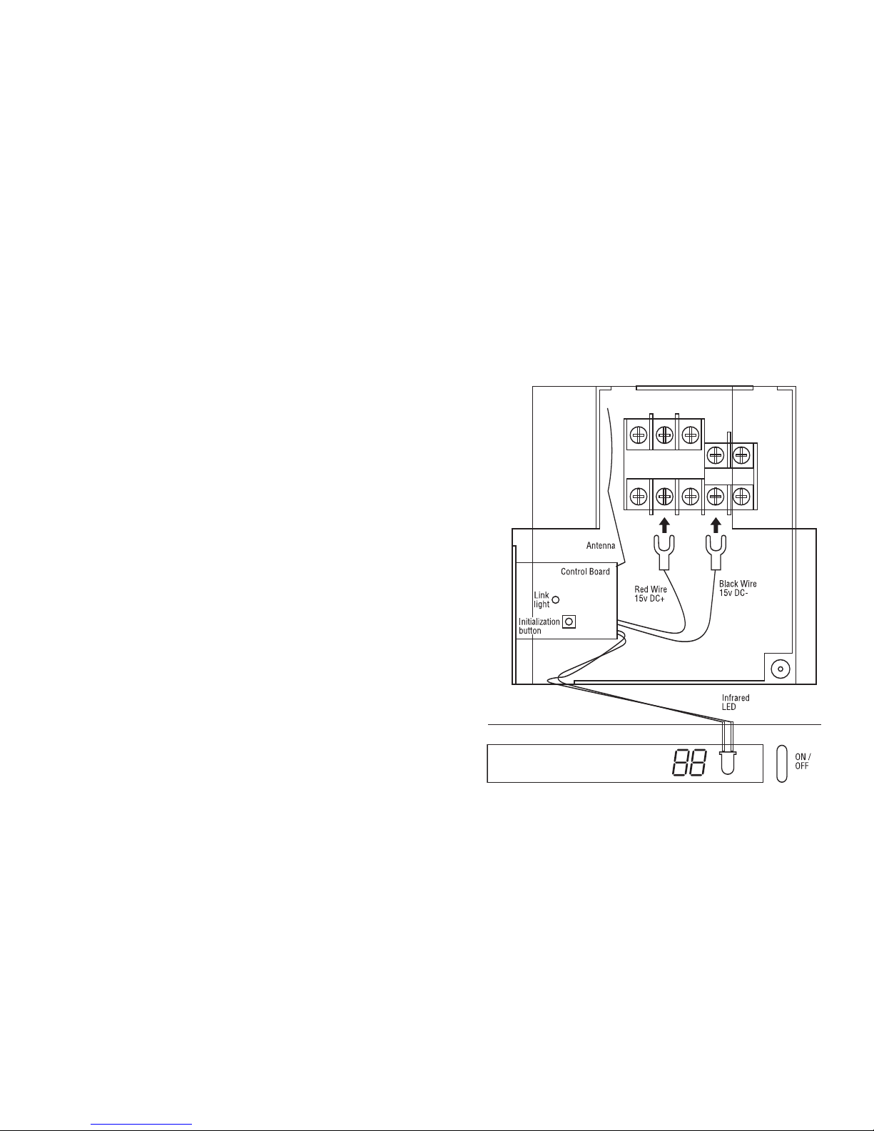
4 Wire the Minisplit Control Card as per the diagram.
Once you have wired the card, place the sensor aligned to
the cover. Remove the adhesive cover and firmly press the
plastic housing to the Mini-split unit.
Installation Diagram of LG Mini-Split Control Board

ADVANCED SETTINGS
The LG Mini-Split Wireless Wall Thermostat Kit is
designed to work seamlessly with the LG Mini-Split
Unit. In many installations multiple units will be
installed so to ensure proper installation and operation each Wireless Wall Thermostat in every room
must be mer
ged within the proximity of the MiniSplit Unit the same room. Follow these steps for
success every time!
STEP 1
On the bottom right of the thermostat touch and release the black
reset button.
• Touch target centre
• When you see the display indicate touch for advanced settings
– touch the screen immediately
•
Now you are ready to setup
the thermostat.
INSTALLING THE THERMOSTAT
Locate your Thermostat approximately 5 ft (1.5m) meters above the
floor. For best results ensure that the thermostat is away from direct
sunlight and on an interior wall.
Using the dimensions 3.2” wide 3.1” (81mm x 78mm) high or the
template included, locate where the thermostat will be placed and cut
out the space on the wall.
Insert the battery backplate into the cut-out area ensuring the top is up
Mark the four inside holes for drilling the 3/16” holes required for the
plastic screw anchors
Remove the battery backplate and drill four (4) 3/16” holes in these
locations.
Insert the plastic gyproc screw anchors and tighten them securely.
Mount the battery backplate using four (4) supplied screws
Insert two (2) D batteries into the recess.
Important: Use only Alkaline
Size D batteries for normal life operation.
Align four (4) pins on the thermostat to the battery backplate and
gently but firmly attach the two units together
Using four (4) 1” screws provided, place them in the four outside
holes and fasten tightly. Replace the top trim.
1 DAYLIGHT TIME : Choose Daylight Time On or Off dependent
on your Time Zone.
ADVANCED SETTINGS - WELCOME
ENERGY WATCH: Enter the HVAC system consumption
parameters (rounded off to kW) as well as your electrical
energy cost (¢/kW) and the ENERGY WATCH feature
will display a real time totals of electrical energy consumption
and cost. To review touch the ENERGY WATCH button on
the MENU SCREEN.
* EXAMPLE: Heat Pump 1kW/ton, 5-30 kW, 7-9¢/kW
ENERGY WATCH feature will run consecutively for 255 days.
If you do not enter your information what will appear on
the display is the total time the Compressor has been
operating.
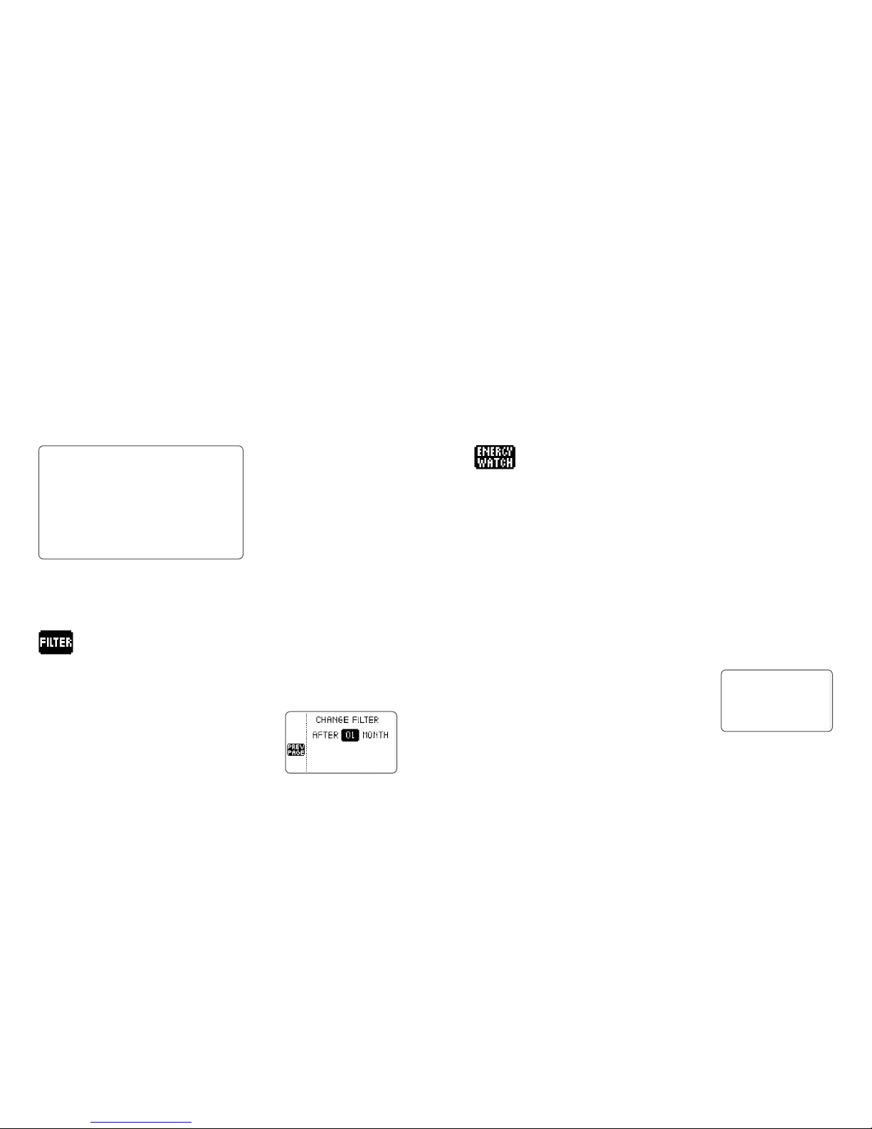
FILTER: Enter the air filter "fan run time" information here.
The Filter Monitor feature uses this information to inform you
when to change or clean your air filter by displaying
CHANGE FILTER icon on the HOME SCREEN.
 Loading...