How it Works
Log In / Sign Up
Buy Points
How it Works
FAQ
Contact Us
Questions and Suggestions
Users
LG
Loading...
D
DCK593W
DCK596MA
DCK787
3
DCS-932L
DD020315PDA
DD127MDWB
DD1411BWM
DD147FDB
DD147FDN
2
DD147MDWB
DD147MWB
DD147MWN
DD147MWWB
DD147MWWM
DD147P3WM
DD148MWB
DD148P2WM
2
DD148P3WM
DD168MPB
DD168MWB
DD168MWN
DD345
DD345-P
DD446-P
DD447-P
DE8421NCA
2
DE8421P
DE8421PCA
2
DE8521P
DE8521PCA
DE8551ECA
DE9353CEM
DE9353UEE
DE9421CPM
DE9453CEM
DE9511CNM
DE9511CPM
DE9513CNM
DE9523P
DE9553CEM
Decoy
5
Decs11ma
Deluxe central controller
DELUXE HIGH WALL MINI SPLIT
3
Des11ea
DES2018EKD
DES2038EKD
2
DF20VVS
DF20WKSE
DF20WKSG
DF20WV
2
DF20WV2EW
DF212FP
DF215FP
4
DF215FW
3
DF22BV2B
DF22RV2S
DF22VV2SB
DF22VV2SBE
DF22VV2SBG
DF22VVS
DF315FPS
DF325FP
DF325FPS
DF325FW
DF415HMS
2
DF415HSS
5
DF425HMS
DF425HSS
DF-599 X
2
DF8901EH
DF8903NH
DF8912NH
DF8945NH
DF9900
DF9900E2H
2
DF9900E4H
2
DF9900NH
2
DF9901P
DF9901PH
DF9911P
DF9911PH
DF9912EH
DF9921N
DF9921P
DF9921PH
DF9933PH
2
DFB227HD
2
DFB325HM
4
DFB415FP
2
DFB425FP
3
DFB512FP
DFB512FW
4
Dfs11ea
DFSWLWT0A
DG
DG1319RD7
DG-9530
DG-9540
DG-979S
Loading...
Loading...
Nothing found
DF20WKSG
Owner's Manual
100 pgs
21.83 Mb
0
Table of contents
Loading...
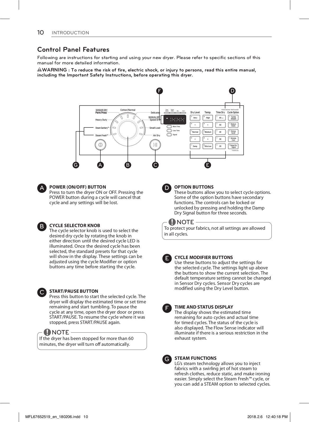
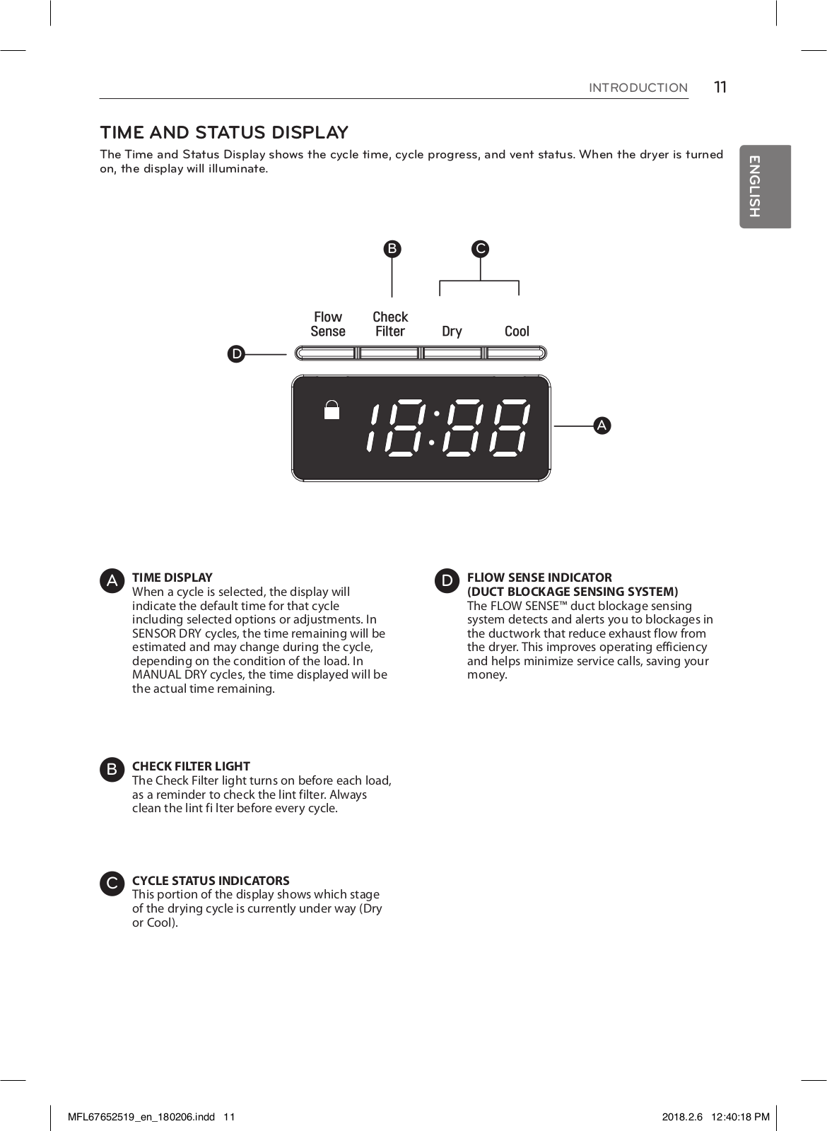
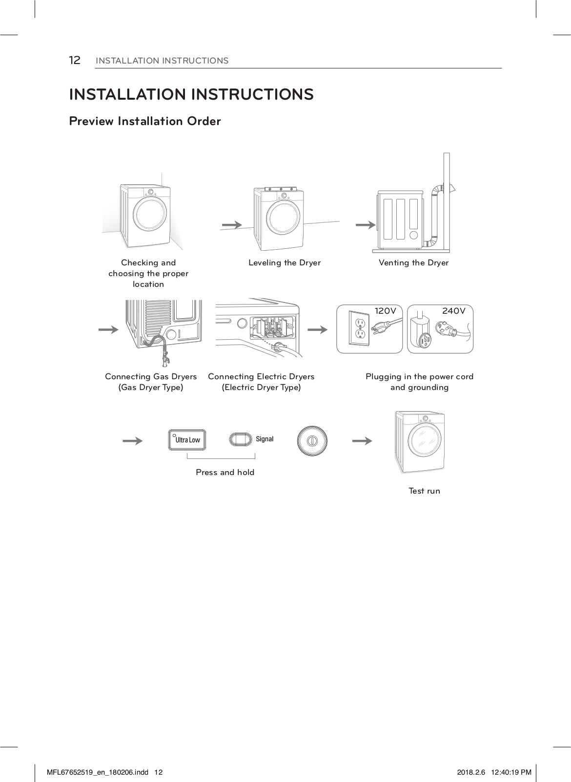
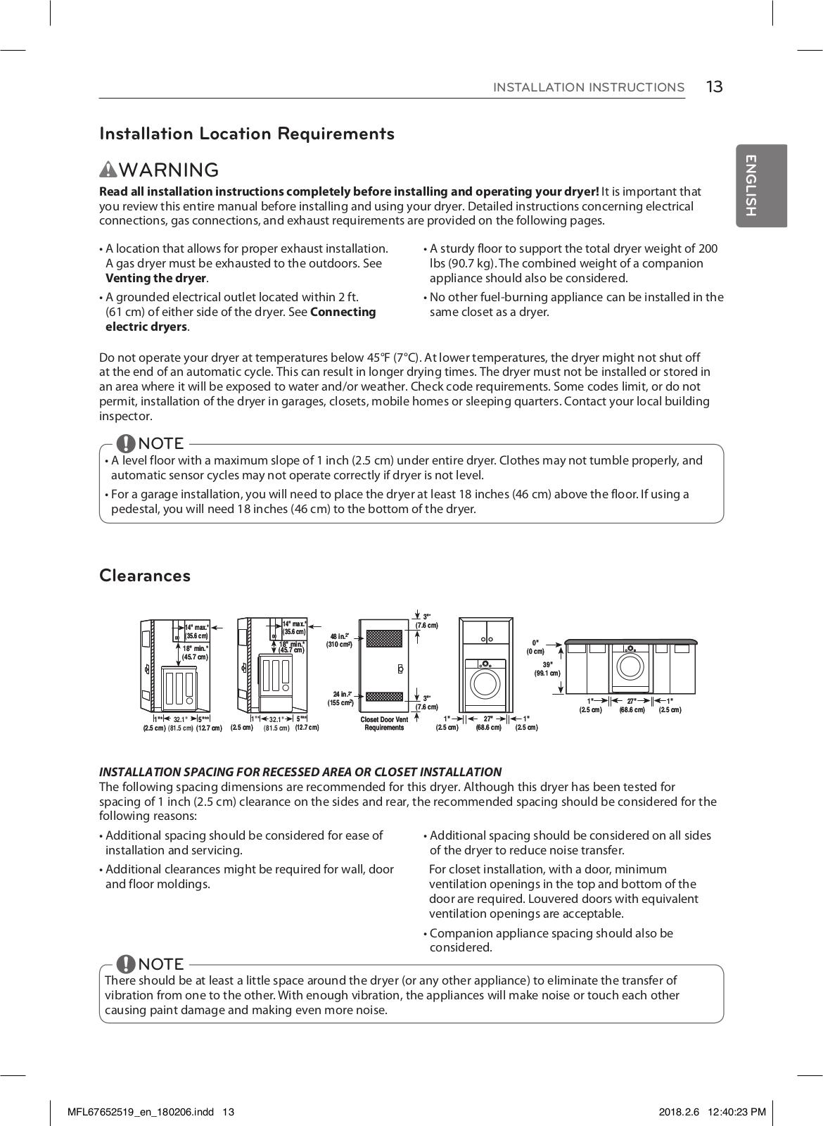
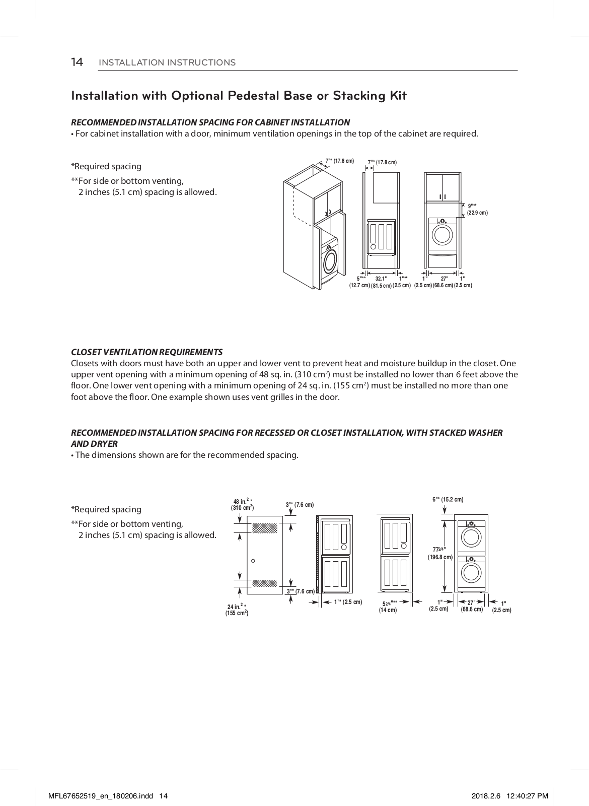
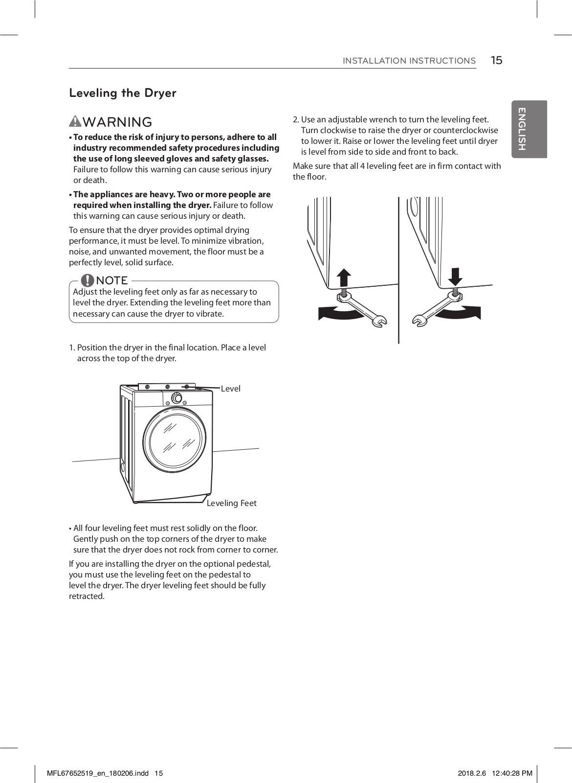
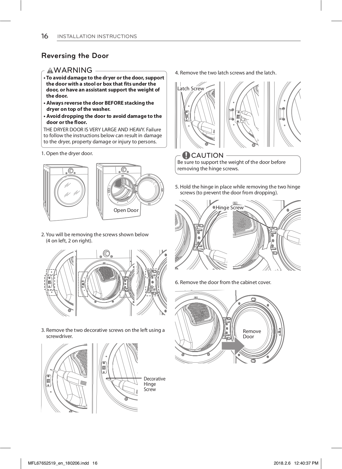
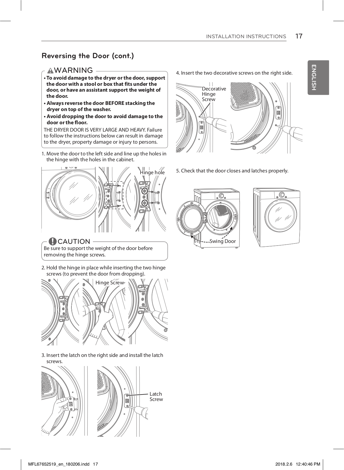
LG DF20WKSG Owner's Manual
...
LG Owner's Manual
Download
Specifications and Main Features
Frequently Asked Questions
User Manual
Download
Loading...
+
70
hidden pages
Unhide
You need points to download manuals.
1 point = 1 manual.
You can buy points or you can get point for every manual you upload.
Buy points
Upload your manuals
 Loading...