

LG Deluxe central controller Installation Manual

LG
Deluxe Central Controller
Installation Manual
LG
IMPORTANT
• Please read this Installation Manual carefully and
thoroughly before installing and operating your room air
conditioner.
• Please retain this Installation Manual for future reference
after reading it thoroughly.
Visit us at : http://www.lgservice.com
ENGLISH ITALIANO ESPAÑOL FRANÇAIS DEUTSCH

2 Deluxe central controller
Deluxe central controller
TABLE OF CONTENTS
■ Safety precautions
............................................................................
3
■ Deluxe Central controller configuration
........................................
7
• Deluxe central controller accessory parts
........................................
7
■ System structure
................................................................................
8
• System configuration
........................................................................
8
■ External wiring diagram
..................................................................
9
•MultiVCRU(N)N
..............................................................................
9
• Multi V Plus & MPS product
...........................................................
10
■ Internal wiring diagram
...................................................................
11
•MultiVCRU(N)N
............................................................................
11
• Multi V Plus & MPS product
...........................................................
12
■ Network interface connection
........................................................
13
• PI 485(M) dip switch configuration
.................................................
13
• CNU connection
..............................................................................
14
■ Indoor unit address setting method
..............................................16
•MultiVCRU(N)N
...........................................................................
16
• Multi V Plus & MPS product
...........................................................
17
■ Installation of Deluxe Central controller program
.......................
19
• Program execution & system set up
...............................................
19
• Program execution procedure
........................................................
20
■ System set-up
..................................................................................
22
• Configuration of system setting screen
..........................................
22
• Example of system setting
.............................................................
25
■ Troubleshooting
..............................................................................
26

Installation manual 3
ENGLISH
Do not operate or stop
the unit by inserting or
pulling out the power
plug.
• It will cause electric shock
or fire due to heat
generation.
Ask for Product
equipment at the service
center or establishment
certainly at the specialty
store.
• It can cause an accident,
electric shock, explosion
or injury.
Use standard parts.
• Use of non standard parts
can cause electric shock,
explosion, injury,
breakdown.
■ Operation
Standard Parts
Safety Precautions
To prevent injury to the user or other people and property damage, the following instructions
must be followed.
■ Incorrect operation due to ignoring instruction will cause harm or damage. The seriousness is
classified by the following indications.
■ Meanings of symbols used in this manual are as shown below.
WARNING
CAUTION
This symbol indicates the possibility of death or serious injury.
This symbol indicates the possibility of injury or damage.
Be sure not to do.
Be sure to follow the instruction.
WARNING
4 Deluxe central controller
If water enters the product, turn the power
switch of the main body of appliance off.
• After taking the power-plug out from the
socket, contact the service center.
Keep the product away from the places
which can have moisture.
• Water may enter the unit and degrade the
insulation. It may cause an electric shock.
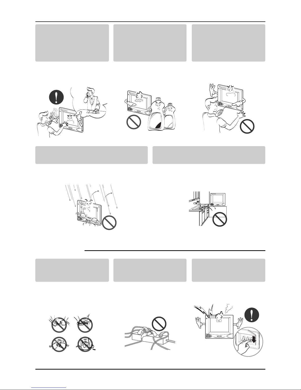
■ During usage
While re-installing the
established product, notify
the service center or
establishment specialty
store.
• It can cause an accident,
electric shock, explosion,
injury.shock.
Do not use the power cord
near Flammable gas or
combustibles, such as
gasoline, benzene, thinner,
etc.
• It may cause an explosion
or fire
Do not disjoint randomly or
repair and remodel the
product.
• It may cause fire and
electric shock
Wax
Thinner
Do not change or extend the
conductor at random.
• It can cause fire and
electric shock.
Do not use concert with in
theoctopus-likelegsway.
• It can cause fire and
electric shock
Unplug the unit if strange
sounds, smell, or smoke
comes from it.
• It may cause fire and
electric shock accident.
Installation manual 5
ENGLISH
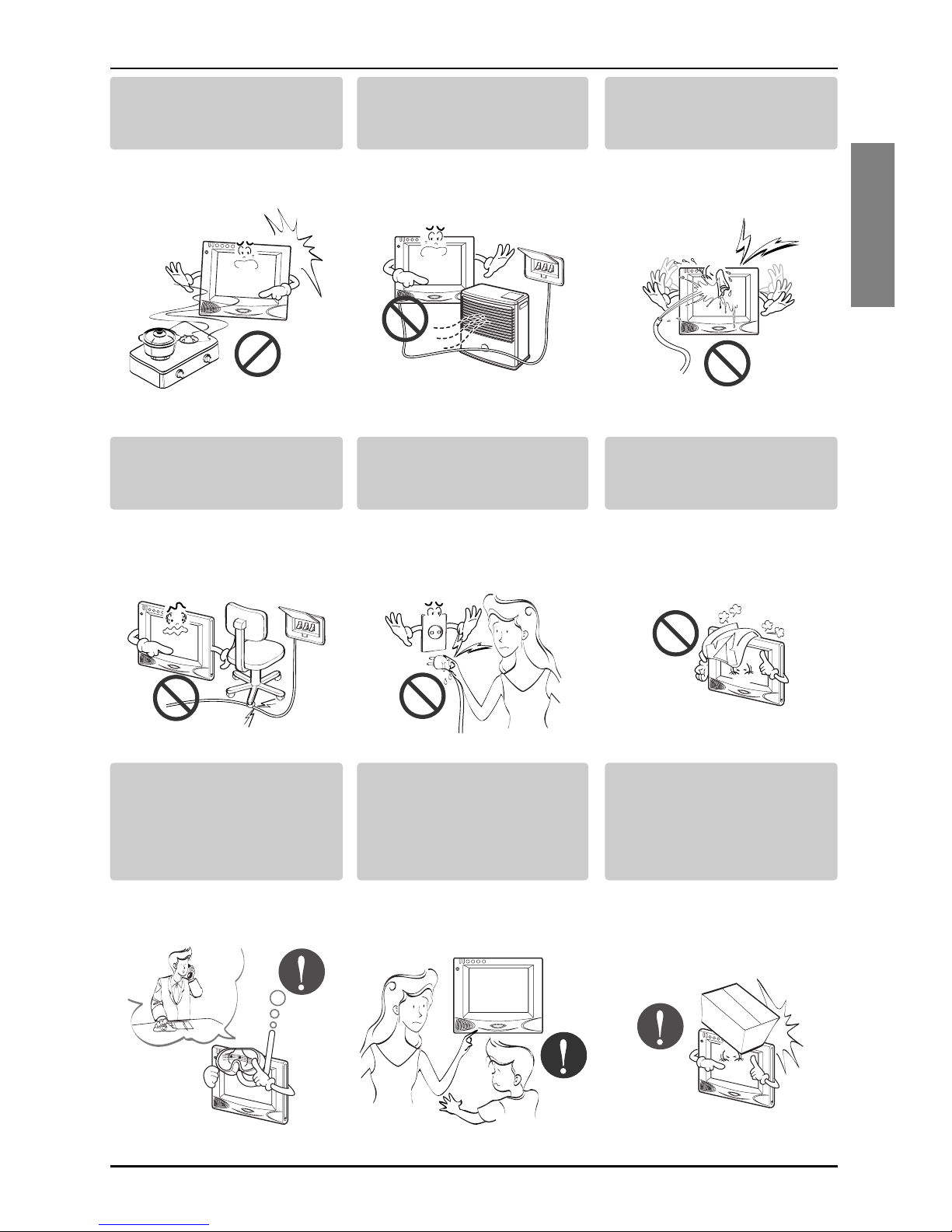
Do not put firearms near
product.
• It can cause fire.
Do not put an electric heater
or conductor near to the
product.
• It can cause fire and
electric shock.
Do not spill water inside
product.
• It can cause electric
shock and breakdown.
Do not place heavy goods
on wire.
• It can cause fire and
electric shock.
Hold the plug by the head of
the power plug when taking
it out.
• It may cause electric
shock and damage.
Do not place heavy goods
on product.
• It can cause product
breakdown.
That increase in case of
product was been flood
certainly in the service
center or establishment
specialty store commit .
• I am responsible for fire
and electric shock.
Protect the product from
handling by a children.
• It can cause accident and
product breakdown.
Do not apply shock to
product.
• I am responsible for
breakdown in case of
shock to product.
6 Deluxe central controller
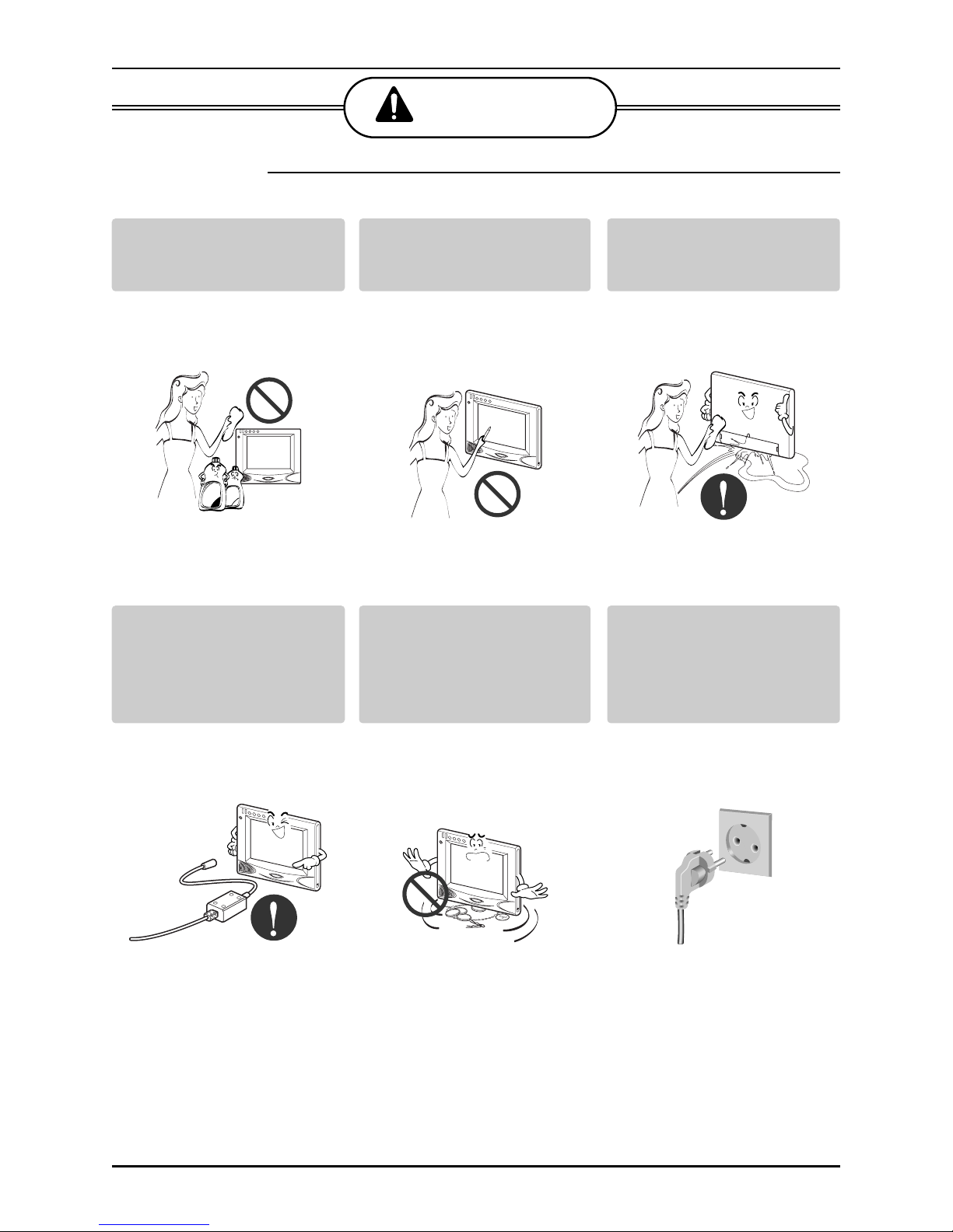
■ During usage
CAUTION
Clean by soft hands using a
cleaning material like a soft
cloth.
• It can result in fire and
product transformation.
Use touch screen with a pen
that product offers.
• Otherwise, there can be
breakdown and damage
to the product.
Do not place any live part on
the surface having water.
• It can cause product
breakdown.
Wax
Thinner
Use recommended Adapter.
• Otherwise it can result in
product breakdown
Avoid contact to the metallic
goods such as necklace,
coin, key, a watch which
may touch the battery even
for a short-time.
• It may cause product
breakdown and injury.
Hold the plug by the head of
the power plug when taking
it out.
• It may cause electric
shock and damage.

Deluxe central controller configuration
Installation manual 7
ENGLISH
Deluxe Central Controller Configuration
Deluxe Central Controller Accessory Parts
210 mm mm
250 mm
22 mm
210 mm
250 mm
Web Pad Frontview Sideview Cradle frontview Sideview
Power Supply External S.M.P.S
Power Cord : 100~250 VAC
50/60 Hz Input
*Note:NotProvided
International standard
IEC320 C8 TYPE
8 Deluxe central controller
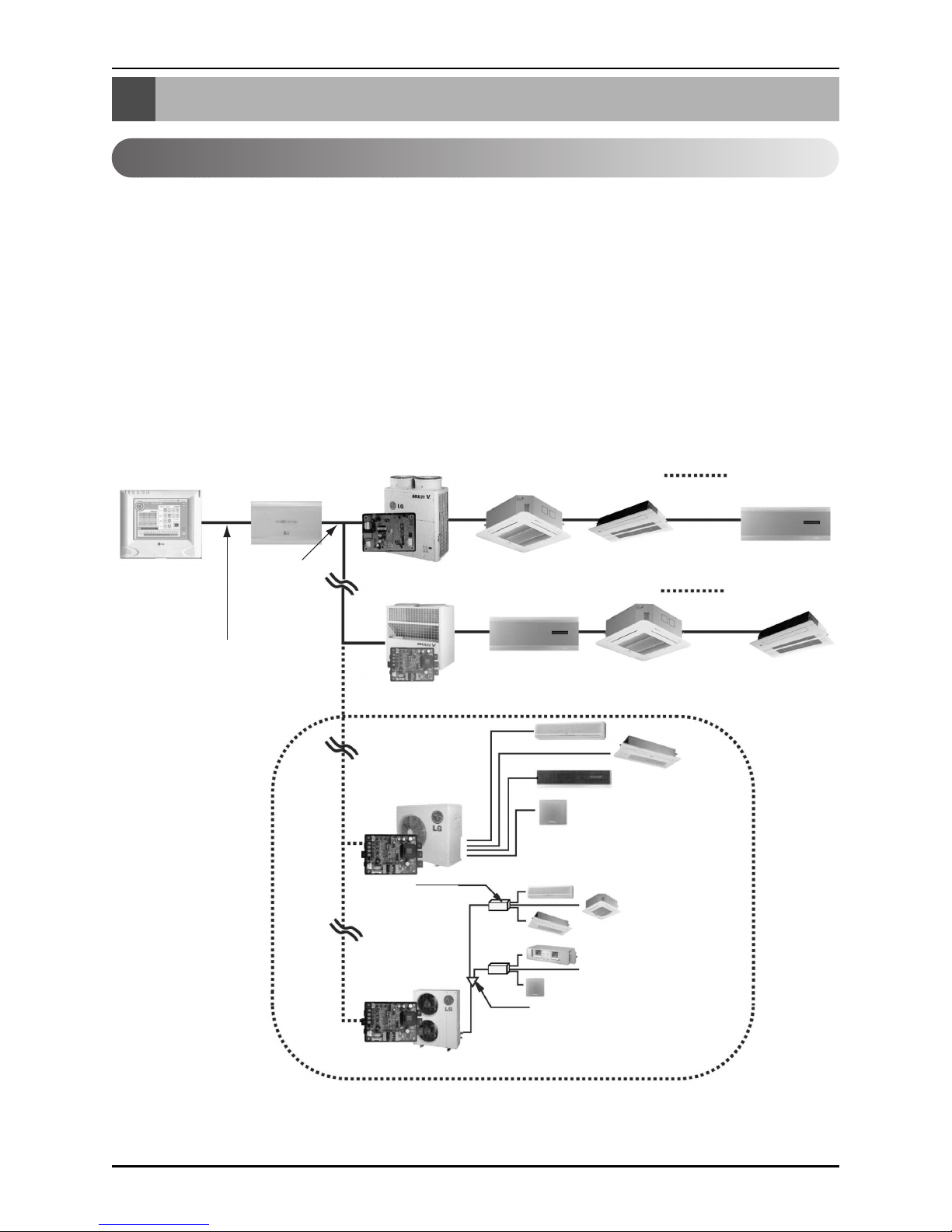
System Structure
System Structure
System Configuration
Deluxe
central
controller
Ethernet
(Cross cable)
PI 485(PQNFP00A0)
PI 485(PMNFP14A0)
MPS Product
PI 485
(PMNFP14A0)
PI 485(PMNFP14A0)
MPS Product
0.75mm
2
X 2C
CNU
(PQNFG00A0)
Multi V
Multi V plus
- 1 Deluxe central controller ↔ 1CNU
-1CNU ↔ 16 PI 485
- 1 PI485 ↔ 1 Outdoor
- 1 Outdoor ↔ 16 Indoors
- The number of maximum indoor units = 256
1. Deluxe central controller
- Centralized control of maximum 256 (16 X 16)
Indoor units
- Simple touch pad control
- GUI setting considering convenience of use
- Power failure compensation with independent
built-in battery (Max. 2 hours)
2. CNU
- Combination of maximum 16 outdoor units
- 485 to ethernet converter built-in
3. PI 485
- 1 pc per outdoor/master unit
If your requirement does not match above mentioned specifications, then please contact LG Airconditioner department for support

Installation manual 9
ENGLISH
External Wiring Diagram
External Wiring Diagram
Multi V CRU(N)N
- Refer the following wiring diagram and connect the communication line accordingly
A, B terminals are connected to Indoor units and C, D terminals are connected to CNU.
* Notice : Indoor unit address setting can be done by rotary switch in the indoor unit pcb
Indoor units
00 01 02 0F
10 11 12 1F
F0 F1 F2 FF
LAN Port
CNU
(PQNFG00A0)
Cross
Cable
Deluxe central controller
BUS A
BUS B
PI 485
PI 485
PI 485
MAIN PCB
Outdoor unit 0
CC
AA
BB
D
VCC VCC
GND GND
D
MAIN PCB
Outdoor unit 1
CC
AA
BB
D
VCC VCC
GND GND
D
MAIN PCB
Outdoor unit 16
CC
AA
BB
D
VCC VCC
GND GND
D
 Loading...