

Page 1
Internal use Only
D4A0081EDF1.C0AAWAA
LG Electronics Technical Service Manual
LED DOWNLIGHT(8W)
MODEL : D4A0081EDF1.C0AAWAA
D4A0083EDF1.C0AAWAA
D4A0085EDF1.C0AAWAA
D4A0081EDF2.C0AAWAA
D4A0083EDF2.C0AAWAA
D4A0085EDF2.C0AAWAA
Caution: Please carefully read the safety precautions within this manual
before operating the product
P/NO : Printed in Korea
Page 2
Revisions
• Established date : 2013. 07. 19
• Revised date : -
• Revision No. : 00
Revision
No.
01 All New 2013.07.19 Hyojin Kim,
Scope Details of revision Revised date Prepared by
Research
Checked by
Document
Management
department
Engineer
-2-
LGE Internal Use Only
Page 3
Before the service
Safety precaution …..........…………………………………………………………………………………… 4
Model name nomenclature ……..………………………………………………………………………… 5
Product specification ………………………………………………………………………………………… 8
During the service
Exploded view ………………………………………………………………………… 10
Service part list …………..…………………………………………………………… 11
Installation environment ……………………………………………………………… 12
Installation method ……………………………………………….…………………… 13
Dimming cable connection … … … … … … … … … … … … … … … … 14
Dimming wiring diagram and capability … … … …… … … … … … … … 15
Incorrect application and use ...........………………………………………………… 16
Troubleshooting ...……………………………………………………………………… 17
Part replacement method …………………………………………………………….. 18
-3-
LGE Internal Use Only
Page 4
Safety Precautions
The meaning of the symbol expressed in this product and manual is as follows.
• The purpose of this symbol is to gain the attention of the user on items or operations that can
cause dangerous situations. To avoid dangerous situations, please read and follow the directions
with the symbol carefully.
• The purpose of this symbol is to show possible electric shock in specific conditions.
Can result in major injury or casualty (death) when the directions are violated.
Can result in minor injury or product damage when directions are violated.
• Do not twist or damage the power cable.
It can cause fire and electric shock.
• When repairing or installing the product, always make sure to turn off the power.
It can cause fire and electric shock.
• Do not connect the polarity of the power arbitrarily.
It can damage the product or cause a safety accident.
• Firmly fixate the product on the ceiling.
It can cause the product to fall down and cause an injury.
• Be careful not to drop or apply impact on the product.
It can cause product failure.
• When the product is turned on, do not directly stare into the lamp.
Strong light can cause visual disorder.
• Do not let any alien particles penetrate into the product, and if alien particles do penetrate
into the product, remove them.
It can cause a safety accident such as electric shock and product damage.
• Do not install the product where the ceiling is uneven.
It can cause the product to fall down, resulting in product damage and injury.
• If the lamp goes off abnormally after the product is installed, check the product according
to the troubleshooting procedure.
Disassembling the product arbitrarily can cause electric shock.
• Have two people install or repair the product if possible.
The product can fall over and cause an injury.
• After installing or repairing the product, make sure that the product is installed
correctly without any gap between the exterior surface and the ceiling. If there is a gap,
rotate the product to check the gap.
• After installing the product, check if there are any alien particles on the surface of the
product.
.
• Do not wipe the product with flammable substance such as alcohol, benzene and acetone
that can degrade the surface of the product.
-4-
LGE Internal Use Only
Page 5
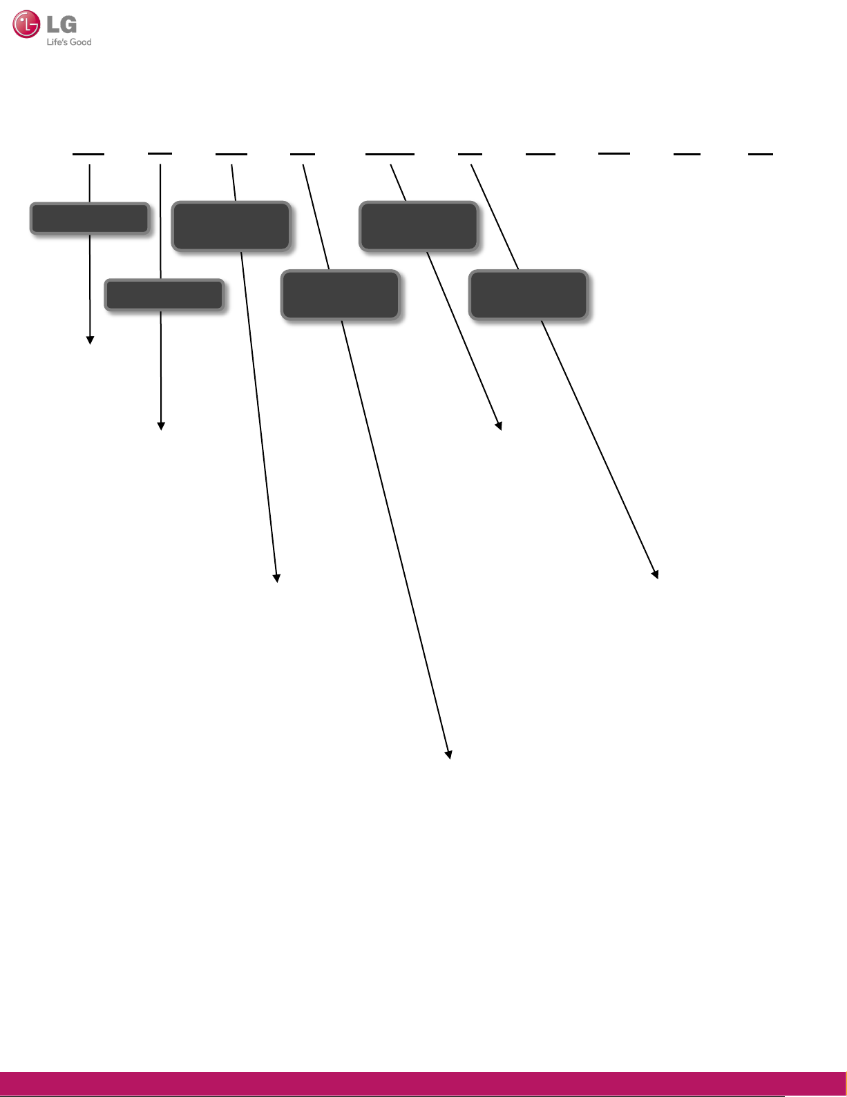
Model name nomenclature (Front)
Classification
DOWNLIGHT
4
Size
3 : 3”
4 : 4”
5 : 5”
6 : 6”
7 : 7”
8 : 8”
9 : 9”
A 0 08 1 F D E
Reflector /
Trim
Installation
Method
Power
Consumption
Color
Temperature
05 : 4.5W
13 : 13W
12 : 120W
D
1
A : White - White
B : White - Silver
C : White - Brushed Nickel
D : Haze Clear - White
E : Haze Clear - Silver
F : Haze Clear - Brushed Nickel
G : Clear - White
H : Clear - Silver
J : Clear - Brushed Nickel
0 : Commercial Power Wire Connection – Round Shape – Fixed Type
1 : Commercial Power Wire Connection – Round Shape – Swivel Type
2 : Commercial Power Wire Connection – Square Shape – Fixed Type
3 : Commercial Power Wire Connection – Square Shape – Swivel Type
0 : 2700K (2725±145)
1 : 3000K (3045±175)
2 : 3500K (3465±245)
3 : 4000K (3985±275)
4 : 4500K (4503±243)
5 : 5000K (5028±283)
6 : 5700K (5665±355)
7 : 6500K (6530±510)
A : Adjustable Color Temperature
-5-
LGE Internal Use Only
Page 6
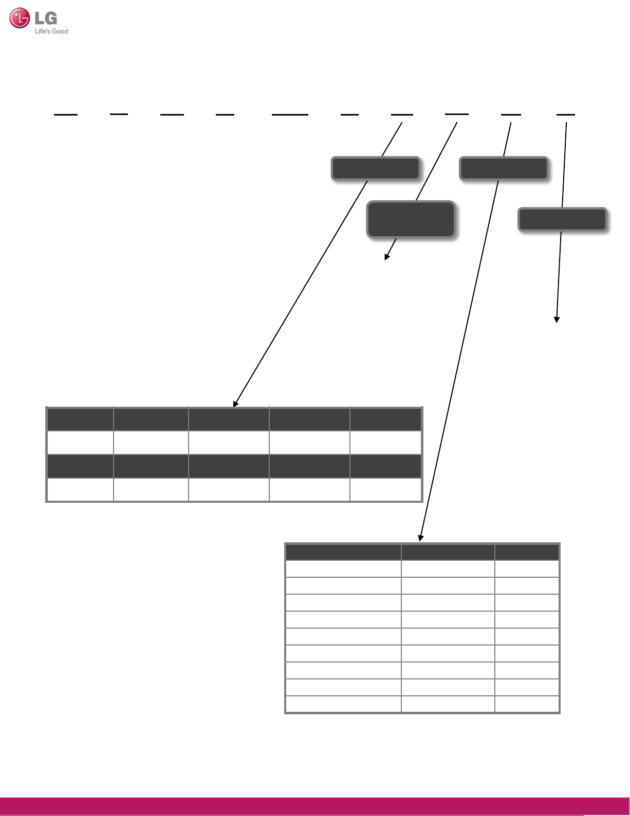
Model name nomenclature (Front)
4
A 0 08 1 F D E
Beam Angle
LED PKG
Maker
A : Cree
B : LiteOn
C : Citizen
D : Innotek
E : Lumileds
F : ILJIN
G : LG Chem
U : UOT- ALEF
H : Seoul Semi
D
Rated Voltage
1
Serial Number
0~9 : Applied according to
the sequential
development
history
Angle[˚] 2Θ½≤20 20<2Θ½ ≤40 40<2Θ½ ≤60 60<2Θ½ ≤80
Model Code A B C D
Angle[˚] 80<2Θ½≤100 100<2Θ½≤120 120<2Θ½≤140 140<2Θ½
Model Code E F G H
Voltage (VAC) Hz Model Code
100V 50/60Hz common A
110V 50/60Hz common B
120V 50/60Hz common C
220V 50/60Hz common D
230V 50/60Hz common E
100 - 240V 50/60Hz common F
220 - 240V 50/60Hz common G
120 - 277V 50/60Hz common H
277V 50/60Hz common J
-6-
LGE Internal Use Only
Page 7

Model name nomenclature (Back)
O
1. Area
2. Branch
CODE Type Language
1 Area English
2 Branch English
AA C W
3,4. Business Type
5. Exterior color
Description
Each area represents a letter written in English should
A : Korea
B : North America
C : Europe
D : Asia
Area (Branch) a letter written in English indicating the referred patients
K : Korea Branch
E ; Middle Southern America
F : Middle East / Africa
6,7. Certification
AA
3, 4
5
6, 7 Certification Number
Business
Type
Exterior
Color
number
English
00 : B2C / B2B / B2G
01 : B2C / B2B
02 : B2G
03 : B2C
04 : B2B
Appearance (body parts) referred to the color of the English abbreviation If you
duplicate the colors indicated with different alphabet letter.
A : Brown
B : Blue
E : Beige
L : Black
P : Pink
R : Red
01 : High Efficiency (Only Korea)
02 : KS (Only Korea)
03 : KC (Only Korea)
04 : High Efficiency / KS (Only Korea)
S : Silver
T : Titan
W : White
X : Bordeaux Purple
0 : No Color
-7-
LGE Internal Use Only
Page 8

Product specification
General specification
This specification applies to all LED flat light models.
1. Electric specification (4” 8W)
Item
Input voltage
(V, rms)
Input current
(A, rms)
Input power
(W, rms)
Input frequency
(Hz)
Test
Min. Typ. Max. Criteria
Conditions
AC 100 230 240
AC 0.027 0.034 0.096
AC (All) 7.2 8 8.64
AC 47 50 53
Rated voltage 10% (230V)
Criteria : 8W + 8%, -10%
Rated Frequency ± 3 Hz
Power factor
Output voltage
(V, rms)
Output current
(A, rms)
Output power
(W, rms)
Efficiency
(%)
AC 0.85
DC 28.00 29.50 30.68
DC 0.191 0.205 0.219
DC 5.34 6.04 6.71
AC (All) 75
Rated Voltage : AC 230V, 50Hz
By LED PKG characteristics change
(bin mixing 4%)
Converter output Tolerance 7%
-8-
LGE Internal Use Only
Page 9

2. Product specification
Classification 4 inch Unit
Watts 8 W
Light Output 520 540 560 lm
Lumens per Watt 65 67 70 lm/W
Light Color 3000 4000 5000 K
Color Accuracy (CRI) > 80
Beam Angle 100 ⁰(angle)
Size
Ф120 ⅹ 88(H)
Product Weight 358 g
AC 230
Input Voltage
(AC 100 – 240)
Input Frequency 50 Hz
Method of Power Input Single Phase Three Wiring System
Dimming 0 - 10V
Operating Temperature -20 ~ 50
mm
V
℃
Power Factor (PF) > 0.85
-9-
LGE Internal Use Only
Page 10

Exploded view
Screw,Machine
Y62708802
V62332001
V62332002
V62332003
SMPS,AC/DC
Screw,Machine
Heat Sink
Spring,Locker
-10-
Case,Body
Cover,Optic
Cover,Guide
LGE Internal Use Only
Page 11

Service Part List
No. Name Applicable model Part No.
1 LED Assembly
D4A0081EDF1.C0AAWAA
D4A0083EDF1.C0AAWAA
D4A0085EDF1.C0AAWAA
D4A0081EDF2.C0AAWAA
D4A0083EDF2.C0AAWAA
D4A0085EDF2.C0AAWAA
D4A0081EDF1.C0AAWAA
EAV62332001
EAV62332002
EAV62332003
EAV62332001
EAV62332002
EAV62332003
2 SMPS, AC/DC
D4A0083EDF1.C0AAWAA
D4A0085EDF1.C0AAWAA
EAY62708802
D4A0081EDF2.C0AAWAA
D4A0083EDF2.C0AAWAA
D4A0085EDF2.C0AAWAA
-11-
LGE Internal Use Only
Page 12

Installation environment
[●:can be installed, ▲: contact manufacturer, X: can not be installed]
Classification 8W
Temperate range (℃) -20 ~ 50℃
Installation
environment
Humidity range (%)
Indoor installation (Fixed facing downward)
Working plant
Indoor gymnasium
Warehouse building
High rise building (Indoor)
Large building (Indoor)
Open square, playground
Park
Large billboard
95% RH <
●
●
●
●
●
●
-
-
-
Large wall
Bridge
Hot and humid environment
Location where gas is used
Location with vibration
Location with metallic dust
Area difficult for A/S
Wireless LAN
-12-
-
-
▲
X
▲
▲
▲
●
LGE Internal Use Only
Page 13

Installation method
-13-
LGE Internal Use Only
Page 14

Dimming Cable Connection
-14-
LGE Internal Use Only
Page 15

Dimming Wiring Diagram and Capability
-15-
LGE Internal Use Only
Page 16

Incorrect Application and Use
※ The following lists incorrect applications/uses.
Please be careful during installation and use in following cases as they can result
in electric shock, injury or skin burn.
No. Incorrect application and use Expected risk
Using product after there was an impact to the product, for example, from dropping
1
Using the product after configuring below the rated current capacity
2
Using the product after disassembling or reconfiguring the product arbitrarily
3
Installing the product in an environment where water can penetrate into the product
Using for underwater lighting purpose
4
(Underwater view, search light, fishing, promotional event etc.)
Using the product without sufficiently drying or repairing the product
5
after the product has been submersed in water
Using the product with excessive power voltage variance. (±10% or more)
6
Fire / Electric shock
Fire / Electric shock
Fire / Electric shock
Electric shock
Fire / Electric shock
Fire / Electric shock
7
8
9
10
11
12
13
14
15
16
17
Using the product with only the power cable connected and without grounding
the product properly
Using the product with excessively bent or damaged power cord
Do not insert pin, coin or metallic wire into the interior/exterior holes on the casing
Using the product while exposed to flammable material nearby
Disassembling the product while in use
Repairing and disassembling the product by unqualified technician
When cleaning, repairing or brushing the product without disconnecting the power
Using for purposes other than lighting. (Heating food, drying clothes, heating etc.)
Moving the product by holding parts other than the main unit.
(Moving the product by holding the reflector etc.)
Moving the product carelessly without considering the weight
Using the product near the heating device
Electric shock
Fire / Electric shock
Fire / Electric shock
Fire / Electric shock
Fire / Electric shock
Fire / Electric shock
Electric shock
Fire / Electric shock
Injury
Injury
Fire / Explosion
18
19
20
21
Using the product in frequently flooding location
Using the product with the power cord arbitrarily cut
Installing and using the product in a humid or wet location
Using the product underwater
-16-
Electric shock
Fire / Electric shock
Fire / Electric shock
Electric shock
LGE Internal Use Only
Page 17

Troubleshooting
No. Problem Checkpoint Resolution
1 Lighting does not work
or flickers
2 Cannot adjust
the brightness
3 Gap between product
and ceiling after
the installation
① Check AC power cable
② Check DC power cable connection
③ Check after replacing LED assembly
④ Check after replacing SMPS
⑤ If abnormal after checking above
① Check connector for dimming
connection
② Check 0~10V interface cable
③ Check after replacing SMPS
④ If abnormal after checking above
① Check if inner side of the ceiling
where product is assembled is even
② Check if the spring is missing
from the heat sink
• Connect the power
• Connect the DC power cable
• Replace LED assembly
• Replace SMPS
• Replace product
• Replace connector for dimming
connection
• Replace 0~10V interface cable
• Replace SMPS
• Request to replace dimmer
• Rotate product to move spring
to location without gap
• After disassembling the product,
reinstall the product after assembling
the spring on the heat sink
4 Weld line or alien
particle is visible on the
surface of cover and
guide after the
installation
5 Hot spot is visible
③ Check if the tension of the spring
is sufficient
④ Check the deformation of cover
and guide
⑤ If abnormal after checking above
① Check the surface of the product
(Scratch, flow mark etc.)
① Check after replacing cover and optic
② Check after replacing LED assembly
③ If abnormal after checking above
※ SMPS is supplied by LG and is replaced on 1:1 product basis.
• Replace spring
• Replace cover and guide
• Connect facility personnel
or call center
• Replace cover and guide
• Replace cover and optic
• Replace LED assembly
• Replace product
-17-
LGE Internal Use Only
Page 18

Part replacement method
Part Picture Direction
SMPS
Case, Body
Cover, Optic
Cover, Guide
Spring
①
①,②,③
①
②
③,④
⑥,⑦,⑧,⑨
④
⑤
① Use electric or manual driver to loosen 2 M3*6
machine screws assembled on SMPS and heat sink.
② Replace the SMPS.
① Use the electric driver to loosen the M3*30
tapping screw assembled on the heat sink
and main unit (Case body, cover guide).
(M3*30 4 screws)
② Disassemble the heat sink from the case body.
③ Disassemble the case body from the cover guide.
④ Disassemble the cover optic from the cover guide.
⑤ Remove the part to replace and replace it with a new part.
⑥ Place the cover optic on the cover guide.
⑦ Place the case body on the cover guide.
⑧ Align the case body groove to that of the heat sink
and place the heat sink on top of the case body.
⑨ Use the electric or manual driver to tighten the M3*30
tapping screw to assemble the heat sink and main unit
(Case body, cover guide). (M3*30 4 screws)
① Use the electric driver to loosen the M3*30 tapping screw
assembled on the heat sink and main unit
(Case body, cover guide). (M3*30 3 screws)
② Disassemble the heat sink from the case body.
③ Separate the heat sink and the spring, and replace
the spring. (2 springs)
④ Align the case body groove to that of the heat sink
and place the heat sink on top of the case body.
⑤ Use the electric or manual driver to tighten the M3*30
tapping screw to assemble the heat sink and main unit
(Case body, cover guide). (M3*30 4 screws)
LED Assembly
Base Assembly,
Rear
①,②,③
①,②,③,④
① Use the electric driver to loosen the M3*30 tapping screw
assembled on the heat sink and main unit
(Case body, cover guide). (M3*30 4 screws)
② Disassemble the heat sink from the case body
③ Disassemble the LED PCB from the heat sink.
(M2*4 4 locations)
④ Replace the LED PCB with a new one. If the insulator is
damaged, replace it as well.
① Use the electric driver to loosen the M3*30 tapping screw
assembled on the heat sink and main unit
(Case body, cover guide). (M3*30 4 screws)
② Disassemble the heat sink from the case body.
③ Disassemble the LED PCB from the heat sink.
(M2*4 4 locations)
④ Replace heat sink, bush or insulator with a new part.
-18-
LGE Internal Use Only
 Loading...