How it Works
Log In / Sign Up
Buy Points
How it Works
FAQ
Contact Us
Questions and Suggestions
Users
LG
Loading...
D
D150
2
D160
7
D160F
D160F-LG
D160G
D160J
D165G
D179NAA
D18AN
D18CN
D18G1N
D18GN
D18HN
D18LV SC0
D18RX
D18RX SC0
D18-SCA6MN
D18-SCB6PN
D18SMV
D18TEH
D18YXA
D19DAH1
D19RIV3
D2000N-PN
2
D2051W
D20F45G
D2102L
D2102R
D2102S
D2102W
2
D213C
D213CJ
D213F
D213n
3
D2141W
D221C
D2241W
2
D2242P
8
D2242P-PN
8
D2242PY
D2302R
D2302W
D2330RW908B
D2340RW908B
D2341P
D2341P-BN
D2341PY
D2342P
21
D2342PB-PN
D2342P-PN
11
D2342PY
D2343P
5
D2343PB
2
D2343PB-BN
D2343P-BN
3
D2350RW908B
D2351R
D2351W
D237IPS
2
D237IPS-PN
2
D242AC
2
D242AC1
D242AH1
D242BC1
D242BF
D242BH1
D242BR
D242EC1
D242EH1
D246RP
2
D2482-60021
D24AN
D24AWN-ND11
D24H1N
D24HN
D24-SCA6MN
D24TEH
D24TFH
D2500N
2
D2500N-PN
10
D2511W
D2522W
2
D2524W
D2525S
D2526W
2
D2532W
D2542P
7
D2542P-PN
8
D2542PY
D2602R
D2602W
D2702V
2
D2702W
D2743P
3
D2743PB
2
D2770P
2
D2770P-PN
6
D2792P-SN
2
D27B48T
D27D51
Loading...
Loading...
Nothing found
D2342PY
User Manual
24 pgs
4.55 Mb
0
Table of contents
Loading...
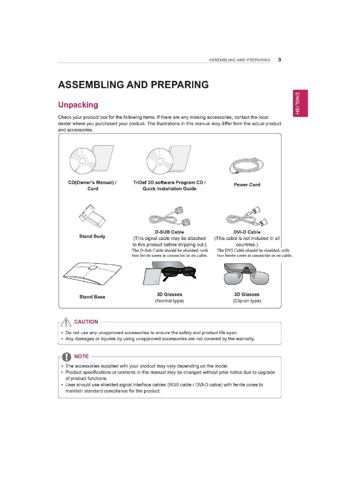
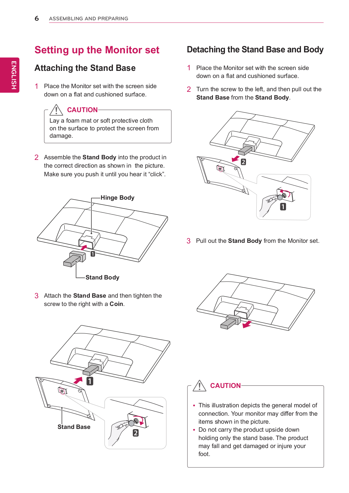
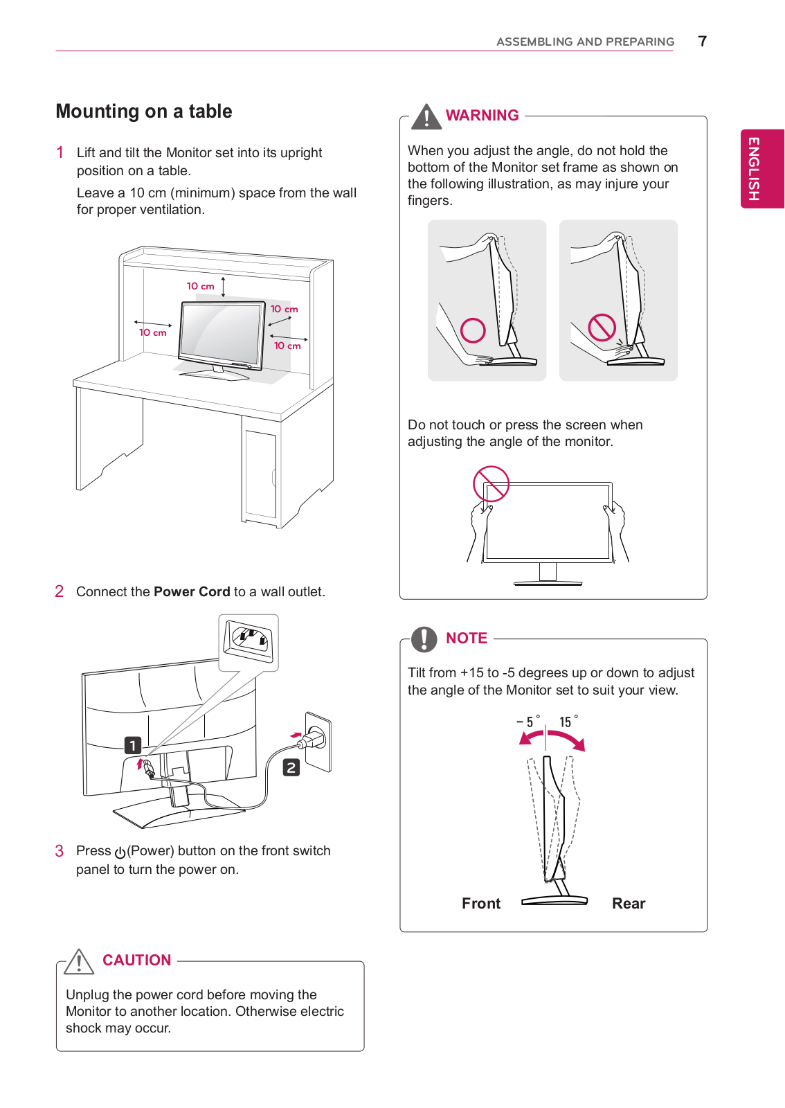
LG D2342PY User Manual
...
LG User Manual
Download
Specifications and Main Features
Frequently Asked Questions
User Manual
Download
Loading...
+
16
hidden pages
Unhide
You need points to download manuals.
1 point = 1 manual.
You can buy points or you can get point for every manual you upload.
Buy points
Upload your manuals
 Loading...