

Page 1
Internal use Only
D2330RW908A.ALWE000
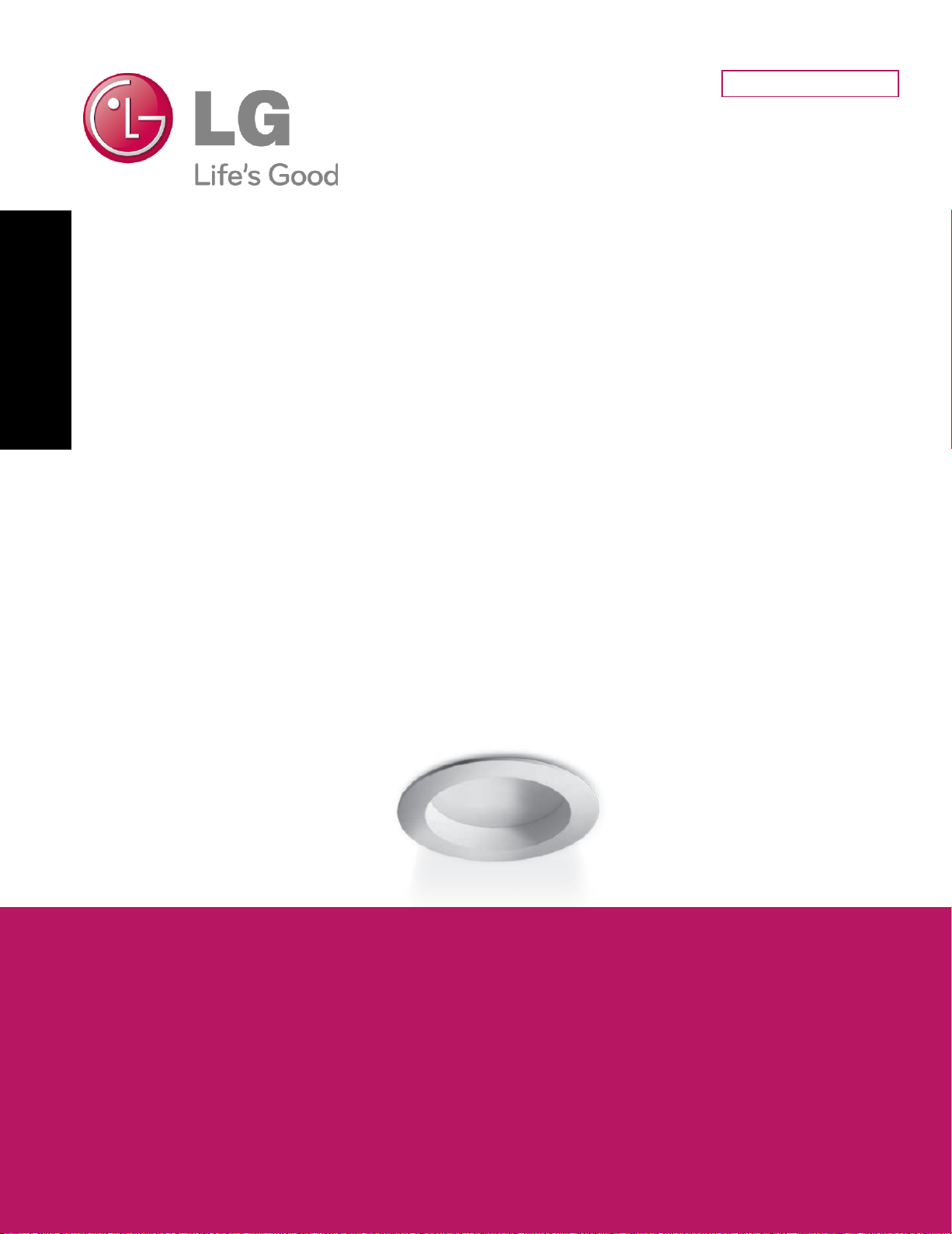
LG Electronics Technical Service Manual
LED DOWNLIGHT(23W)
MODEL : D2330RW908A.ALWE000
D2340RW908A.ALWE000
D2350RW908A.ALWE000
D2330RW908B.ALWE000
D2340RW908B.ALWE000
D2350RW908B.ALWE000
Caution: Please carefully read the safety precautions within this manual
before operating the product
P/NO : Printed in Korea
Page 2
Revisions
• Established date : 2013. 07. 19
• Revised date : -
• Revision No. : 00
Revision
No.
01 All New 2013.07.19 Hyojin Kim,
Scope Details of revision Revised date Prepared by
Research
Checked by
Document
Management
department
Engineer
-2-
LGE Internal Use Only
Page 3

Before the service
Safety precaution …..........…………………………………………………………………………………… 4
Model name nomenclature ……..………………………………………………………………………… 5
Product specification ………………………………………………………………………………………… 9
During the service
Exploded view ………………………………………………………………………… 11
Service part list …………..…………………………………………………………… 12
Installation environment ……………………………………………………………… 13
Installation method ……………………………………………….…………………… 14
Dimming cable connection ………………………………………… 15
Dimming wiring diagram and capability……………………………………… 16
Incorrect application and use ...........………………………………………………… 17
Troubleshooting ...……………………………………………………………………… 18
Part replacement method …………………………………………………………….. 19
-3-
LGE Internal Use Only
Page 4
Safety Precautions
The meaning of the symbol expressed in this product and manual is as follows.
• The purpose of this symbol is to gain the attention of the user on items or operations that can
cause dangerous situations. To avoid dangerous situations, please read and follow the directions
with the symbol carefully.
• The purpose of this symbol is to show possible electric shock in specific conditions.
Can result in major i nj ur y or casual ty (death) when t he dir ec ti ons are violated.
Can result in minor i nj ur y or product damage when di rec ti ons are violated.
• Do not twist or damage the power cable.
It can cause fire and electric shock.
• When repairing or installing the produc t, always make sure to turn off the power.
It can cause fire and electric shock.
• Do not connect the polarity of the power arbitrarily.
It can damage the product or cause a safety accident.
• Firmly fixate the product on the ceiling.
It can cause the product to fall down and cause an injury.
• Be careful not to drop or apply impact on the product.
It can cause product failure.
• When the product is turned on, do not directly stare into the lamp.
Strong light can cause vi sual disorder.
• Do not let any alien particles penetrate into the product, and if alien particles do penetrate
into the product, remove them.
It can cause a safety accident such as elec tr i c s hock and pr oduc t damage.
• Do not install the product where the ceiling is uneven.
It can cause the product to fall down, resulting in product damage and injur y.
• If the lamp goes off abnormally after the product is installed, check the product according
to the troubleshooting procedure.
Disassembling the pr oduc t arbitrarily can cause electric s hock .
• Have two people install or repair the product if possible.
The product can fall over and cause an injury.
• After installing or repairing the product, make sure that the product is installed
correctly without any gap between the exterior surface and the ceiling. If there is a gap,
rotate the product to check the gap.
• After installing the product, check if there are any alien particles on the surface of the
product.
.
• Do not wipe the product with flammable substance such as alcohol, benzene and acetone
that can degrade the surface of the product.
-4-
LGE Internal Use Only
Page 5
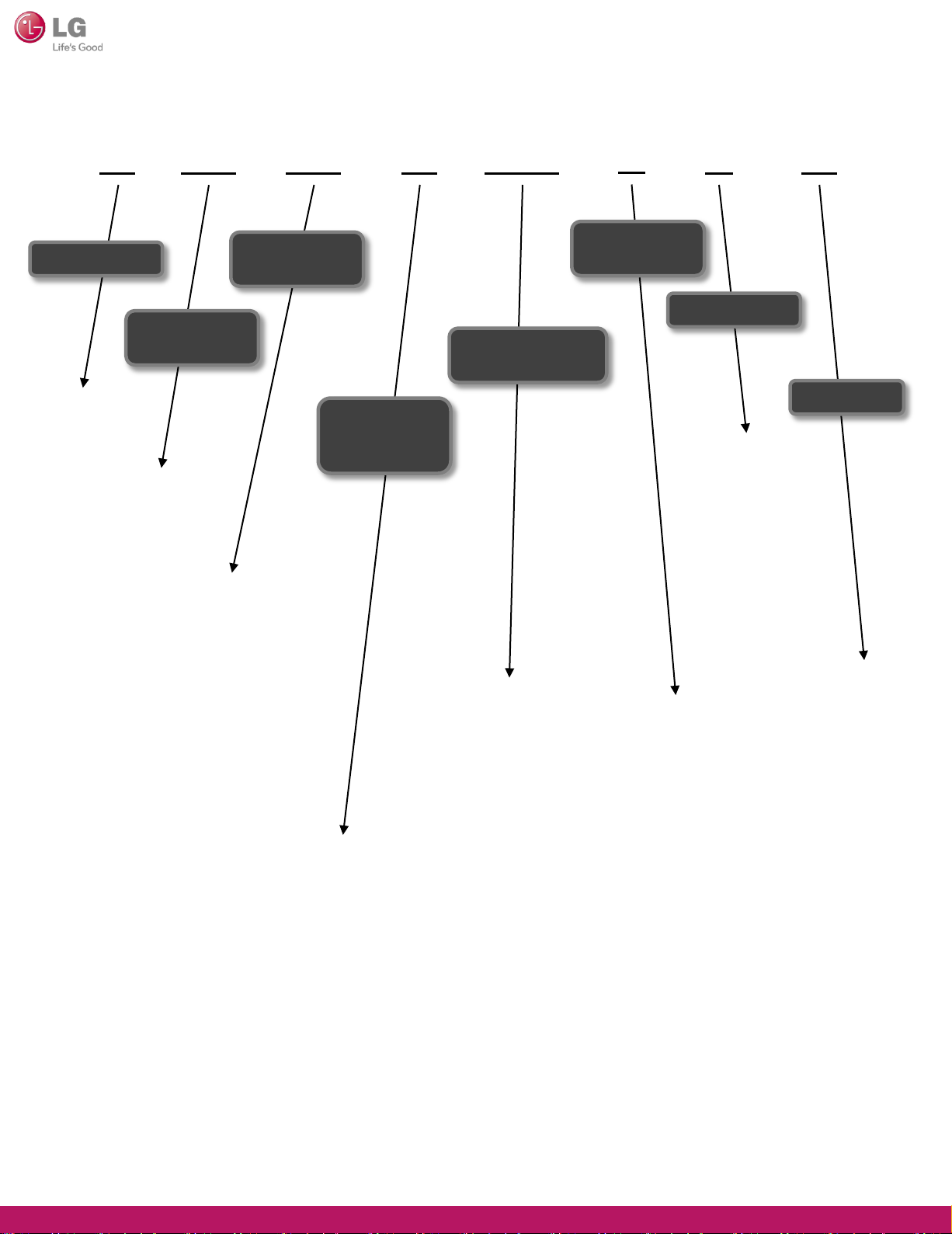
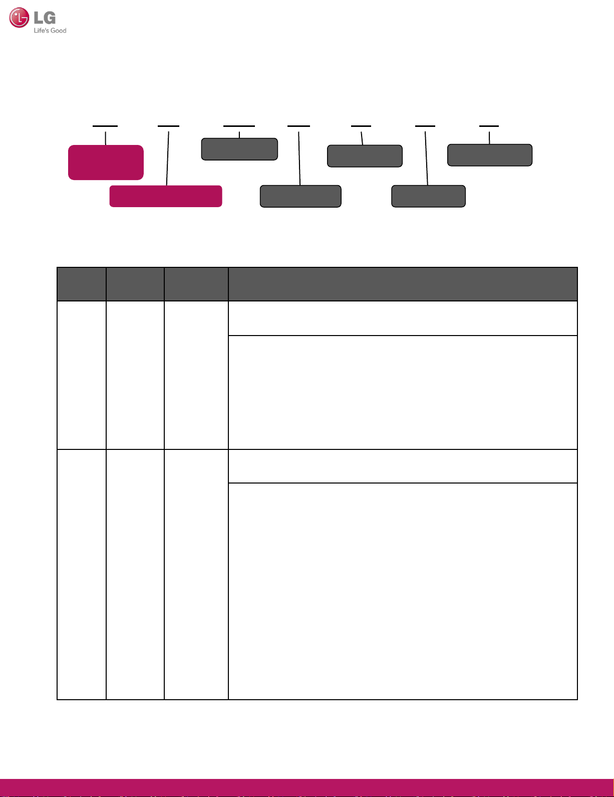
Model name nomenclature (Front)
Classification
DOWNLIGHT
27 : 2700K (2725±145)
30: 3000K (3045±175)
35 : 3500K (3465±245)
40: 4000K (3985±275)
45 : 4500K (4503±243)
50: 5000K (5028±283)
57 : 5700K (5665±355)
65 : 6500K (6530±510)
A : Adjus table Color Temperature
23
Power
Consumption
13 : 13W
23 : 23W
30 R
Color
Temperature
Socket /
Installation
Form
Included Mount Frame
B : Bar Hanger (US)
C : C – Channel (US)
D : Remodel (US)
M : etc. Mount Frame
Excluded Mount Frame
E : E26 Retrofit(US)
R : Recessed
S : Surface
W9 8 D
Reflector Type /
Trim
C : Specular
(Clear)
S : Semi-Specular
H : Haze
B : Baffle
W : White plastic
1 : 10 ≤ 2Θ½ <20
2 : 20 ≤ 2Θ½ <30
3 : 30 ≤ 2Θ½ <40
4 : 40 ≤ 2Θ½ <50
5 : 50 ≤ 2Θ½ <60
6 : 60 ≤ 2Θ½ <70
7 : 70 ≤ 2Θ½ <80
8 : 80 ≤ 2Θ½ <90
9 : 90 ≤ 2Θ½
W : Wall washer
0
Extra
Function
0 : 0~10V
2 : RS-232
4 : RS-485
5 : DMX512
T : Triac
D : DALI
E : Ethernet
U : fUll-2way
Z : Zigbee
F : wi-Fi
R : Radio
frequency
W : z-Wave
Y : Infrared
raYs
A
Platform Size
4 : 4 inch(Round)
5 : 5 inch(Round)
6 : 6 inch(Round)
7 : 7 inch(Round)
8 : 8 inch(Round)
Serial
A : 1st
Development
(In-house)
nd
B : 2
Development
(In-house)
C : 3
Development
(In-house)
rd
-5-
LGE Internal Use Only
Page 6
Model name nomenclature (Back)
L
1. Product
Type
2. Origin Country
CODE Type Language Description
1
Product
Type
Eng.
W E 0 A 0
3.Look/Color
4. Area
• Classified by product types
ex) A : Set (Set Supply)
C : CKD (Part Supply)
S : SKD ( Module and Half-Product Supply)
5. Branch
0
6.MKT Serial
7.Certification
2
Origin
Country
Eng.
Number
• Classified with Manufacturer and Origin Country.
L : LG Korea (Included Gumi,
ex)
Chang-Won, Pyeong-Taek)
C : China
D : Indonesia
K : Turkey
M : Mesico
N : India
P : Polland
T : Thailand
U : United States of America
V : Vietnam
Z : Brazil
-6-
LGE Internal Use Only
Page 7

Model name nomenclature (Back)
1. Product
CODE
L
Type
2. Origin
Country
Type Language Description
W A
3.Look/Color
• Appearance (body parts) referred to the color of the English
abbreviation If you duplicate the colors indicated with different
alphabet letter.
• Exterior Color
예)
E 0 0
5. Branch
4. Area
N : browN
L : bLue
E : bEige
B : Black
P : Pink
R : Red
0
7.Certification
6.MKT Serial
S : Silver
T : Titan
W : White
X : bordeauX purple
Z : Non
3
Look/
Color
Eng.
-7-
LGE Internal Use Only
Page 8

Model name nomenclature (Back)
L
1. Product
Type
2. Origin
Country
CODE Type Language Description
4 Area Eng,
W A
3.Look/Color
• Only one letter representative of origin country
A : Korea
E 0 0
5. Branch
4. Area
0
6.MKT Serial
7.Certification
5 Branch Eng.
6
7 Certification
MKT
Serial
Eng.
Number /
Eng.
• Only one letter representative of Branch
K : Korea branch
• Serial classification at Korea marketing
• Applied sequentially according to Marketing Issue
• Classification of development process and method
: Number(Out-Sourcing), Eng.(In-house)
0 : KC, High efficiency, KS (non-compulsory certification will
obtain)
1 : High efficiency Only (KC included)
2 : KS Only (KC included)
3 : KC Only
4 : High efficiency / KS (KC included)
-8-
LGE Internal Use Only
Page 9

Product specification
General specification
This specificati on applies to all LED flat light models.
1. Electric specification (8” 23W)
Item
Input voltage
(V, rms)
Input current
(A, rms)
Input power
(W, rms)
Input frequency
(Hz)
Tes t
Min. Typ. Max. Criteria
Conditions
AC 100 230 240
AC 0.086 0.105 0.25
AC (All) 20.7 23 25.07
AC 57 60 63
Rated voltage ± 10% (230V)
Criteria : 23W +9% -10%
Rated Frequency ± 3 Hz
Power factor
Output voltage
(V, rms)
Output current
(A, rms)
Output power
(W, rms)
Efficiency
(%)
AC 0.9
DC 28.27 29.45 30.63
DC 0.608 0.640 0.672
DC 27.32 30.97 34.45
AC (All) 80 85
Rated Voltage : AC 230V, 50Hz
By LED PKG characteristics change
(bin mixing ± 4%)
Converter Output Tolerance ± 5%
-9-
LGE Internal Use Only
Page 10

2. Product specification
Classification 8 inch Unit
Watts 23 W
Light Output 1800 1900 1950 lm
Lumens per Watt 78 82 84 lm/W
Light Color 3000 4000 5000 K
Color Accuracy (CRI) 82
Beam Angle 100 ⁰(Degree)
Size
Ф223 ⅹ 85(H)
Product Weight 1263 g
AC 230
Input Vol tage
(AC 100 – 240)
Input Frequency 50 Hz
Method of Power I nput Single Phase Three Wiring Sys tem
Dimming 0 - 10V
Operating Temperature -20 ~ 50
mm
V
℃
Power Factor (PF) More than 0.90
-10-
LGE Internal Use Only
Page 11

Exploded view
Y63032801
1
SMPS,AC/DC
7
Harness
11
SMPS,AC/DC
2
Heat Sink
V62271901
V62271902
V62271903
Screw,Machine
4
Insulator Sealing
8
Case,Body
Cover Bracket
3
Bush
5
Spring,Locker
6
LED Module
9
Cover,Optic
10
Cover,Guide
-11-
12
Gasket
LGE Internal Use Only
Page 12

Service Part List
No. Name Applicable model Part No.
1 LED Assembly
D2330RW908A.ALWE000
D2340RW908A.ALWE000
D2350RW908A.ALWE000
D2330RW908B.ALWE000
D2340RW908B.ALWE000
D2350RW908B.ALWE000
D2330RW908A.ALWE000
EAV62271901
EAV62271902
EAV62271903
EAV62271901
EAV62271902
EAV62271903
2 SMPS, AC/DC
D2340RW908A.ALWE000
D2350RW908A.ALWE000
EAY63032801
D2330RW908B.ALWE000
D2340RW908B.ALWE000
D2350RW908B.ALWE000
-12-
LGE Internal Use Only
Page 13

Installation environment
[●:can be installed, ▲: contact manufacturer, X: can not be installed]
Classification 8W
Temperate range (℃) -20 ~ 50℃
Installation
environment
Humidity range (%)
Indoor installation (Fixed facing downward)
Working plant
Indoor gymnasium
Warehouse building
High rise building (Indoor)
Large building (Indoor)
Open square, playground
Park
Large billboard
95% RH
●
●
●
●
●
●
-
-
-
<
Large wall
Bridge
Hot and humid environment
Location where gas is used
Location with vibration
Location with metallic dust
Area difficult for A/S
Wireless LAN
-13-
-
-
▲
X
▲
▲
▲
●
LGE Internal Use Only
Page 14

Installation method
-14-
LGE Internal Use Only
Page 15

Dimming Cable Connection
-15-
LGE Internal Use Only
Page 16

Dimming Wiring Diagram and Capability
-16-
LGE Internal Use Only
Page 17

Incorrect Application and Use
※ The following lis ts incorrect appl icati ons /uses .
Please be careful during installation and use i n foll owing cases as they can result
in electric shock, injury or skin burn.
No. Incorrect applica tion and us e Expected risk
1
2
3
4
5
6
7
8
9
10
11
Using product after there w as an impact to the product, f or example, from dropping
Using the product after configuring below the rated current capacity
Using the product after disassembling or reconfiguring the product arbitr arily
Installing the product in an environment where water can penetrate into the product
Using for underwater lighting purpose
(Underwater view, search light, fishing, promotional event etc.)
Using the product without sufficiently drying or repairing the product
after the product has been submersed in water
Using the product with excessive power voltage variance. (±10% or more)
Using the product with only the power cable c onnected and without grounding
the product properly
Using the product with excessively bent or damaged power cord
Do not insert pin, coin or metallic w ire into the interior/exterior holes on the casing
Using the product while exposed to flammable material nearby
Disassembling the product w hile in use
Fire / Electric shock
Fire / Electric shock
Fire / Electric shock
Electric shock
Fire / Electric shock
Fire / Electric shock
Electric shock
Fire / Electric shock
Fire / Electric shock
Fire / Electric shock
Fire / Electric shock
12
13
14
15
16
17
18
19
20
21
Repairing and disassembling the product by unqualified technician
When cleaning, repairing or brushing the product without disconnecting the power
Using for purposes other than lighting. (Heating food, drying clothes, heating etc.)
Moving the product by holding parts other than the main unit.
(Moving the product by holding the reflector etc.)
Moving the product carelessly without considering the weight
Using the product near the heating dev ice
Using the product in frequently flooding location
Using the product with the power cord arbitrarily cut
Installing and using the product in a humid or wet location
Using the product underwater
-17-
Fire / Electric shock
Electric shock
Fire / Electric shock
Injury
Injury
Fire / Explosion
Electric shock
Fire / Electric shock
Fire / Electric shock
Electric shock
LGE Internal Use Only
Page 18

Troubleshooting
No. Problem Checkpoint Resolution
1 Lighting does not work
or flickers
2 Cannot adjust
the brightness
3 Gap between product
and ceiling after
the installation
① Check AC power cable
② Check DC power cable connection
③ Check after replacing LED assembly
④ Check after replacing SMPS
⑤ If abnormal after checking above
① Check connector for dimming
connection
② Check 0~10V interface cable
③ Check after replacing SMPS
④ If abnormal after checking above
① Check if inner side of the ceiling
where product is assembled is even
② Check if the spring is missing
from the heat sink
• Connect the power
• Connect the DC power cable
• Replace LED assembly
• Replace SMPS
• Replace product
• Replace connector for dimming
connection
• Replace 0~10V interface cable
• Replace SMPS
• Request to replace dimmer
• Rotate product to move spring
to location without gap
• After disassembling the product,
reinstall the product after assembling
the spring on the heat sink
4 Weld line or alien
particle is visible on the
surface of cover and
guide after the
installation
5 Hot spot is visible
③ Check if the tension of the spring
is sufficient
④ Check the deformation of cover
and guide
⑤ If abnormal after checking above
① Check the surface of the product
(Scratch, flow mark etc.)
① Check after replacing cover and optic
② Check after replacing LED assembly
③ If abnormal after checking above
※ SMPS is supplied by LG and is replaced on 1:1 product basis.
• Replace spring
• Replace cover and guide
• Connect facility personnel
or call center
• Replace cover and guide
• Replace cover and optic
• Replace LED assembly
• Replace product
-18-
LGE Internal Use Only
Page 19

Part replacement method
Part Picture Direction
SMPS
Case, Body
Cover, Optic
Cover, Guide
Spring
①
①
①,②,③
②
③,④
⑥,⑦
④
⑤
① SMPS is a form that is separate from the module..
① Use the electric driver to loosen the M 3* 30
tapping screw assembled on the heat sink
and main unit (Al plate, cover guide).
(M3*30 4 screws)
② Disassemble the heat sink from the Al plate.
③ Disassemble the heat sink from the cover guide.
④ Disassemble the cover optic fr om the cover guide.
⑤ Remove the part to replace and replace it with a new part.
⑥ Place the cover optic on the cover guide.
⑦ tapping screw to assemble the heat sink and main unit
(Case body, cover guide). (M3*30 4 screws)
① Use the electric driver to loosen the M 3* 30 tapping screw
assembled on the heat sink and main unit
(Case body, cover guide). (M3*30 3 screws)
② Disassemble the heat sink from the case body .
③ Separate the heat sink and the spring, and replace
the spring. (2 springs)
④ Align the case body groove to that of the heat sink
and place the heat sink on top of the case body.
⑤ Use the electric or manual driver to tighten the M3*30
tapping screw to assemble the heat sink and main unit
(Case body, cover guide). (M3*30 4 screws)
LED Assembly
Base Assembly,
Rear
①,②,③
①,②,③,④
① Use the electric driver to loosen the M 3* 30 tapping screw
assembled on the heat sink and main unit
(Case body, cover guide). (M3*30 4 screws)
② Disassemble the heat sink from the case body
③ Disassemble the LED PCB from the heat sink.
(M2*4 4 locations)
④ Replace the LED PCB with a new one. If the insulator is
damaged, replace it as well.
① Use the electric driver to loosen the M 3* 30 tapping screw
assembled on the heat sink and main unit
(Case body, cover guide). (M3*30 4 screws)
② Disassemble the heat sink from the case body .
③ Disassemble the LED PCB from the heat sink.
(M2*4 4 locations)
④ Replace heat sink, bush or insulator with a new part.
-19-
LGE Internal Use Only
 Loading...