

Page 1
ADJUSTMENT INSTRUCTION
These instructions are applied to only NC-5AA chassis.
Notes
1.So this is a hot chassis, you must be careful, and be caution
not to touch 1st and 2nd concurrently.
2.Adjustment must be done in the correct order.
3.Power supply of a SET which is adjusted is 100~240V
A.C./50~60Hz.
4.The receiver must be operated for about 30 minutes proir to
the adjustment.
CONTENTS
1) VIF, AFT and SIF Adjustment
2) Sound Multiplex Adjustment
3) FOCUS Adjustment
4) AGC Adjustment
4)-1 Picture AGC Adjustment
5) V-Size and V-Center Adjustment
6) Horizontal Size, Center and Side Pincushion Adjustment
7) Purity and Convergence Adjustment
8) White Balance Adjustment
9) SUB-Bright Adjustment
10) Vertical Center Adjustment
11) Horizontal Center Adjustment
1. VCO and AFT Adjustment
This Adjustment must be applied only to PCB Assy.
1.1. Necessary Instruments
1) Sweamer Generator : can sweep 35MHz~55MHz(over
120dBu)
2) PLUG in Unit : With PIF(45.75MHz), SIF(41.25MHz) Marker
3) Alignment Scope : X-Y mode, 10mV~20V Variable
4) D.C. Power Supply : 0~12V Variable
5) D.C. Power Supply : 13.5V±0.2V (over 300mA)
6) Digital Multimeter
1.2. Preliminary Steps
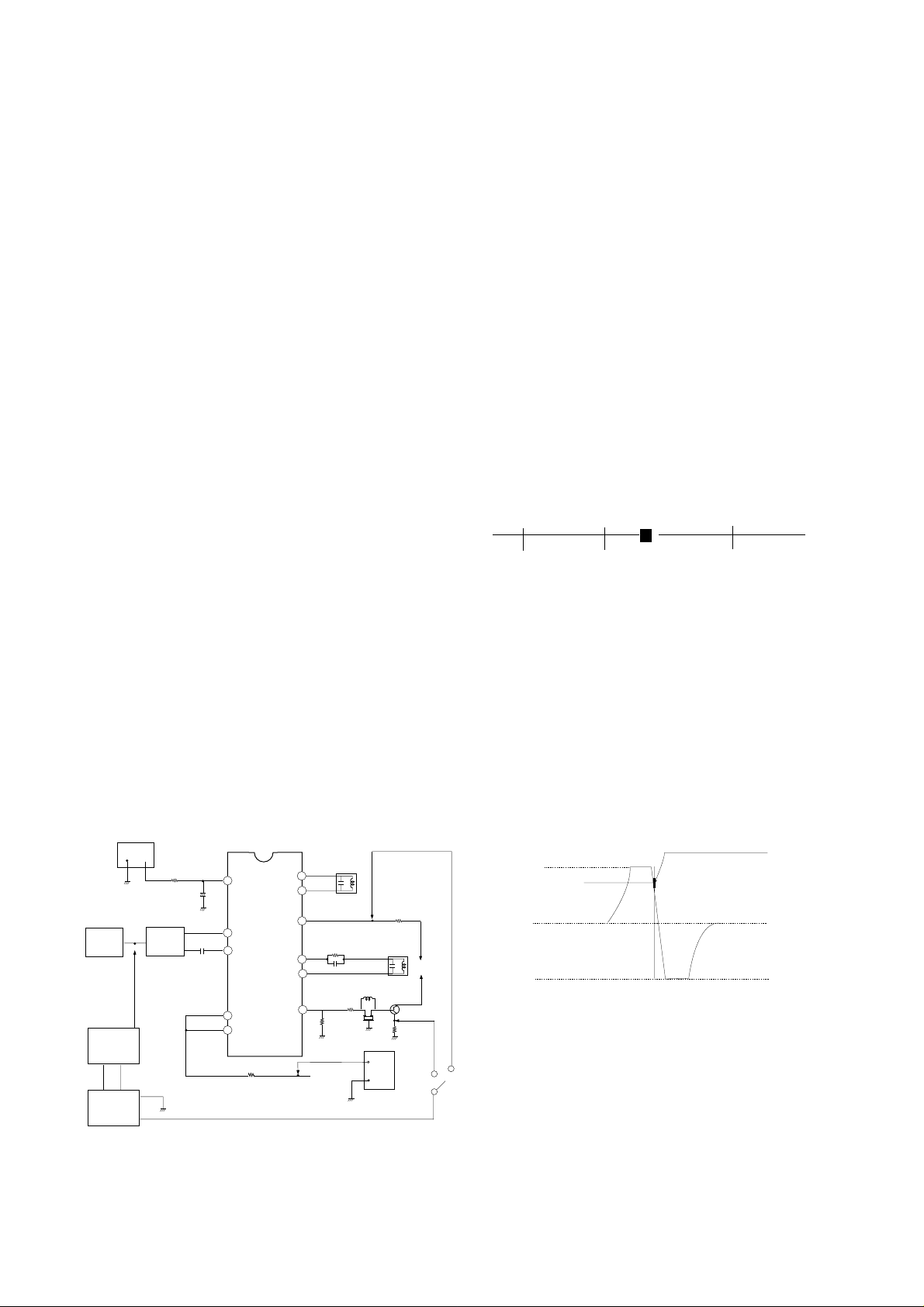
1) Connect the output of Sweamer Generator like <Fig 1>.
Here, set the output of Sweamer Gen. to 100±5dBu.
POWER
SUPPLY
-
TUNER
IF
SWEEMAR
GENERATOR
+
ALIGNMENT
SCOPE
TP2
+
SAW
FILTER
470/0.5W
7.5V
TP11
+
C122
2
C508
8
9
IC501
LA7674
11
14
R591
TP12
<Figure 1>
L501
VCO COIL
51
50
47
R520
46
C521
45
44
R518
TP4
R507
L506
AFT COIL
9V
Q503
R517
L503
Z502
TP3
L502
12.5V
+
POWER
-
SUPPLY
D502
+B
2) Connect H.Scope and Pulse output of Sweamer Generator
to H.Input and Marker input of Alignment Scope,
respectively.
3) Apply AGC Voltage(D.C.) to TP11 of IC201.(7.5±0.05V)
4) Apply B+ of IC201 to TP12 of R591.(12.0±0.1V)
5) Set VR526(AGC Adjustment) to mechanical center.
1.3. Adjustment
A. VCO
1) Set the vertical range of Alignment Scope to 1V/DIV and
CAL position, and, by applying D.C. 0~9V, do DC
Calibration to place D.C 4.5V point of waveform to center of
Screen.
2) Connect the Input terminal of Alignment Scope to
TP3(Video Detection Output), and set Vertical Variable
Switch to CAL position.
3) Apply AGC Voltage to TP11 of IC201 through 470§to be
7.5±0.05V
4) Adjust L501 so that BEAT appears on 45.75MHz Marker
like <Fig 2> If not, adjust again after attenuating output 10
~20dBu.
42.75
B. AFT
1) Connect the Input of Alignment Scope to TP4 with keeping
DC voltage of 2pin of IC201.
2) Keep the output of Sweamer Generator 100±5dBu.
3) Adjust L506 so that waveform of Alignment Scope to be
that of <Fig 3>.
4) Adjust Vertical Volume of Alignment Scope to place DC
level of waveform to center (4.5V) and 45.75MHz Marker to
7.5V¡0.5V.
9V
8V
AFT
0V
2. SIF Adjustment
VCO
2.1. Necessary Instruments
1) Sweamer Generator : can sweep 3~6MHz
2) Plug In Unit : with 4.5MHz Marker
3) Alignment Scope : X-Y mode(can measurable 10mV~
20Vp-p)
4) DC Power Supply : 13.5V, over 300mA
5) DC Power Supply : 0~12V variable
f (MHz)
45.0 47.25
45.75MHz
(Turn L105 so that the position of Beat
is same with 45.75MHz Marker)
<Figure 2>
45.75 MARKER
<Figure 3>
- 1-
Page 2
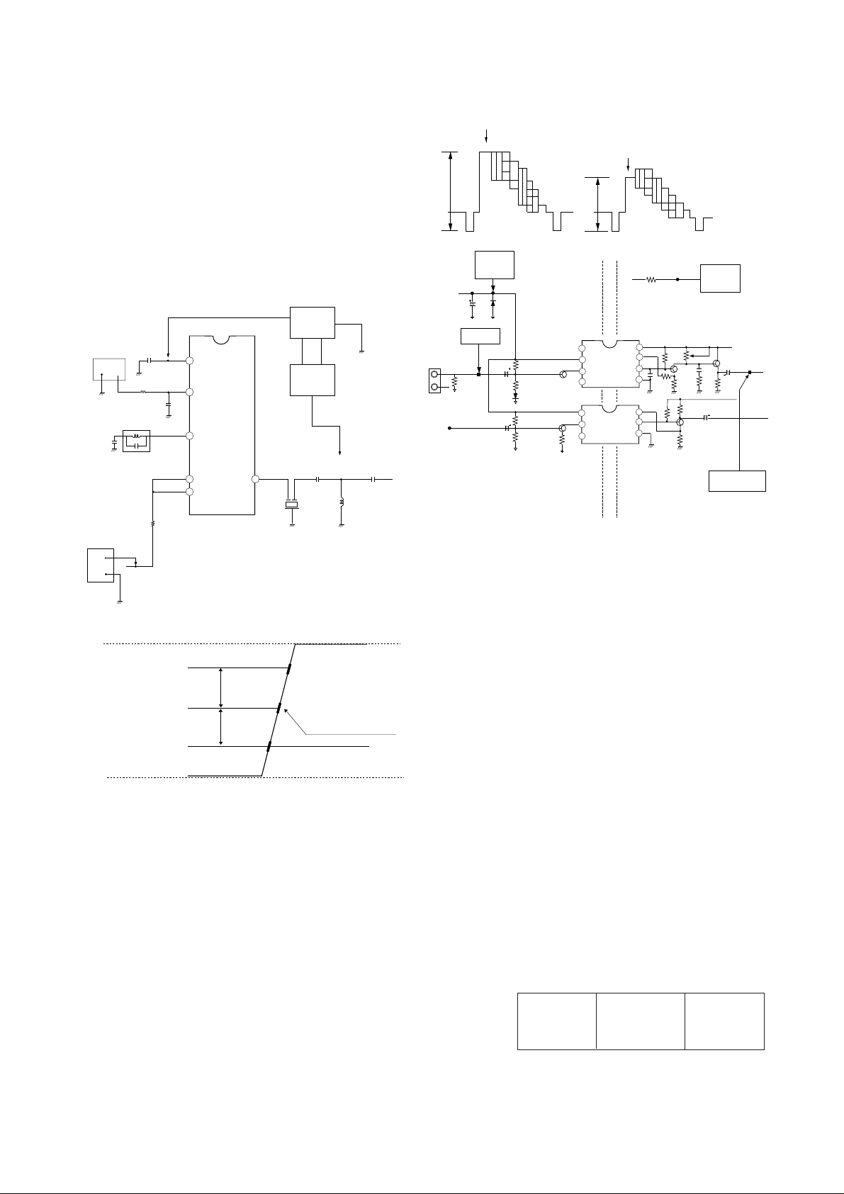
2.2. Adjustment
1) Connect Sweamer Generator and Alignment Scope the
same method of VIF adjustment.
2) Connect the output of Sweamer Generator to TP5 like <Fig 4 >.
3) Connect the Input of Alignment Scope to TP6.
4) Apply AGC voltage of IC201 to TP11(7.5±0.05V).
5) Apply B+ of IC201 to TP12.
6) Adjust L502 S-shaped waveform of Alignment Scope to be
that of <Fig 5>.
Adjust (A=B)
Because 4.5MHz Marker doesn’t with horizontal line, apply
(a) marker(4.5MHz) to be the center of (b), (c)Markers.
100% WHITE
75% WHITE
A
B
DC POWER
SUPPLY
DC 12V
TP13
R591
TP12
<Figure 6>
DC POWER
SUPPLY
DC 12.5V
12.5V
POWER
SUPPLY
9V
A = B
+B
POWER
-
+
ALIGNMENT
SCOPE
TP6
7.5V
TP11
+
C508
1
2
4
11
14
IC501
LA7674
SWEEMAR
GENERATOR
TP5
45
C515
C516
Z501
SUPPLY
C509
+
470/0.5W
L502
SIF COIL
R591
-
TP12
C206
ZD201
PATTERN
A/V IN
VIDEO
SOUND
R609
GENERATOR
TP8
A
R210
1
2
Q206
IC202
C204
C507
3
4
1
Q603
2
IC601
3
COLD
8
7
6
5
8
7
6
HOT
VR202
Q201
R618
Q601
Q202
L201
C510
OSCILLOSCOPE
C201
6.0MHz
VIDEO
SOUND
TP10
D
<Figure 7>
3.3 Adjustment
Adjust VR202 to get Luminance signal(Color Bar) level like
below. ( Refer to <Fig 6> )
1) White 100% modulated 1.78±0.1Vp-p
<Figure 4>
2) White 75% modulated 1.46±0.1Vp-p
4. Automatic Gain Control(AGC) Adjustment
4.1Turn on a SET and receive Digital Pattern of 65¡1dB through
A
(b)
(a)
B
4.5 MARKER
75§Ant. terminal.
4.2 Connect DMM(Digital Multi-Meter) to J27.
4.3 Adjust VR101 to read 5.7±0.05V of DMM.
(Where, you can set proper AGC voltage according to signal
condition.)
0V
(c)
<Figure 5>
3. Composite Video Signal Adjustment
3.1.Necessary Instruments
1) Pattern Generator : PM5518(PHILIPS) or Equivalents
7 Step Color Bar Pattern with 75§out
2) Oscilloscope : VP-5650A or Equivalents
can measure over 1.0Vp-p
Vertical Freq. : over 4MHz
3) DC Power Supply : 12.2±0.2V/400mA 2EA
3.2. Preliminary Steps
1) Connect the output of Pattern Generator to TP8 like <Fig 7>.
Where, the output of Pattern Generator is 1.0Vp-p.(Point
position “A”)
2) Connect DC Power Supply to TP12 and TP13.
Where, devide Ground of TP12 and TP13(HOT/COLD).
3) Connect probe to TP10(point “D”).
- 2-
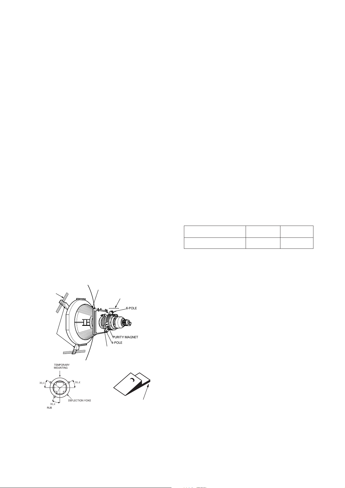
5. Purity and Convergence Adjustment
This adjustment should be made when a complete re-alignment
is required or a new picture tube is installed.
5.1 Purity Adjustment
5.1.1 Necessary instruments and Preliminary steps
1) Pattern Generator : 216/1 or Equivalents
2) Degauss CPT and Cabinet with Degaussing coil.
3) Maximize Contrast level.
4) Pre-adjust the DY.
5.1.2 Adjustment
1) Receive Raster signal(Red).
2) Push the DY to get Picture like <Fig 8>.
3) Adjust 2-pole magnet to place RED center of screen
orthogonally.
B
<Figure 8>
RG
Page 3
4) Pre-fix 2-pole magnet after adjustment with Lock Ring.
,,,,,
5) Pull the DY back slowly to get uniformly RED picture and fix
it.
5.2 Convergence Adjustment
5.2.1 Necessary Instruments
1) Pattern Generator : 216/1 or Equivalents
2) Degaussing coil
5.2.2 Preliminary Steps
1) Do this adjustment after operating the SET more than 30
minutes.
2) Degauss CPT and Cabinet with Degaussing coil.
3) Receive Cross hatch pattern.
4) Adjust Contrast and Bright properly.
5) Untighten half-fixed Magnet Assy lock ring
5.2.3 Adjustment
A. Center(Static) Convergence Adjustment
1) Unify Red and Blue vertical lines at center of screen by
varying the angle of two tabs of 4-pole magnet.
2) Rotate tab with sustaining the angle of item 1) and unify
Red and Blue vertical lines at center of screen.
3) Unify Red,Blue and Green vertical lines by adjusting two
tab2 of 6-pole magnet.
4) Rotate tab with sustaining the angle of item 3) and unify
Red,Blue and Green vertical lines.
5) To get more detail adjustment repeat 1),2) with
remembering changes of Red,Blue and Green.
6) Fix magnet assy lock ring.
B. Dynamic Convergence Adjustment
1) Prepare bonded rubber wedge.
2) Adhere rubber wedge to “A” part halfly.
(Don’t remove paper of bonding part.)
3) Move the DY every direction to get best convergence in
every corner.
4) Adhere rubber wedge to bottom of CPT.(Refer <Fig 9>).
5) After checking the locatons of 3 wedges and check
Convergence.
6) Paint white lacquer on DY fixing nut and magnet.
ADHESIVE TAPE
RUBBER
WEDGES
TEMPORARY
MOUNTING
DEFLECTION YOKE
PURITY &CONVERGENCE
MAGNET ASSEMBLY
,,,
,,
,,
,,,
PURITY MAGNET
4-POLE
GLASS CLOTH TAPE
6-POLE
6. White Balance
6.1 White Balance Adjustment
6.1.1 Necessary Instrument
1) White BAlance Meter
6.1.2 Preliminary Steps
1) Do this adjustment after operating the SET more than 30
minutes.
2) Receive Standard White pattern.
3) Adjust under “APC ON” condition.
4) Turn Screen VR CCW.
5) Set Red driver(VR571) and Blue driver(VR572) to
mechanical center.
6) Set Red Bias(VR574) ,Blue Bias(VR575) and Green
Bias(VR573) to 1/3 point to Clock-wise from full CCW.
7) Set SVC SW to “SVC” to get Horizontal line.
6.1.3 Adjustment
1) Turn screen VR slowly to see first horizontal line on screen
2) Make horizontal line white with 2 Bias VRs which aren’t
displayed in 1).
3) Vary screen VR to get very dim horizontal line.
4) Set SVC SW to “Normal” position.
5) Receive adjustment signal-White in upper and Black in
Lower.
6) Vary Red driver(VR571) and Blue driver(VR572) to get
White screen in White.
7) Vary Bias and Drivers to get the best screen in White and
Black.
8) Check adjustment condition with White Balance Meter.
9) Refer below for Adjustment
Color Temperature
10,000K
High Light : 40fl
Low Right : 4fl
X
0.281
Y
0.288
7. Focus Adjustment
1) Receive Digital pattern.
2) Set screen conditon to “APC ON”.
3) Turn Focus VR to get the best condition in center and
every corner.
8. Sub-Bright Adjustment
1) Receive Digital pattern.
2) Do this adjustment after operating the SET more than 30
minutes.
3) After selecting Sub-mode with SVC Remocon and vary to
distinguish 4 and 5 step of Gray scale.
9. Vertical Size Adjustment
1) Receive Digital pattern and set screen conditon to “APC
ON”.
2) Vary Vertical Size adjustment VR(VR301) to reach inner
circle of large circle to edge of frame.
30¡£
RUBBER WEDGES
LOCATION
30¡£
30¡£
DEFLECTION YOKE
<Figure 9>
ADHESIVE
10. Vertical Center Adjustment
1) Receive Digital pattern and set screen condition to “APC
ON”.
2) Adjust the center of screen with SVC SW(SW301) to place
center.
11. Horizontal Center Adjustment
1) Receive Digital pattern and set screen condition to “APC
ON”.
2) Adjust the center of screen with VR505 to place center.
- 3-
Page 4

- 1 -
BLOCK DIAGRM
TUNER
HOT
COLD
TU100
IC2
D801
IC301
IC801
RL801
D/G
COIL
IC1
PA1
5V 12V 33V
LOCK
CLOCK
DATA
CS
35
3
1
2
5
39 41
SDA/SCL
R, G, B, Ys
Q806
Q10
Q401
Q402
1877
H. D. T
Q805
TMP67CC31
IC501
8
9
50
51
45
46
44
48
T402
FBT
1
3
40
34
6
21
23 28
LA7674
SMPS TRANS
TX
IC601
PRE-AMP
EEPROM
12V
R-Y, B-Y, G-Y
5V
24V
180V
STR50092K
PWR
Q11
FBP
FROM FBT
H.Vcc of
IC501
AFT
HV
Z101
VIF
SIF
VCO
AFT
SHARP
BRI
COLOR
TINT
CONT
PRE-AMP.
Q102
SIF-IN
DET-OUT
SFE4.5
TPS4.5
SP
AUDIO IN VIDEO IN
2 12
IC602
CPT
1 4
T403
-Y
TDA
2006
IC202
Q208
Q603
3
2
9
5
6
10
HT
24V
12V
FBP
B+
COL
CPT
TO IC1
TO CPT
TO T403
CPT
JA001
PCB
13
26
D/G
3
1
6
5
8
Page 5

- 1 -
1. No Raster
Check if FBT PIN3 is 112V.
Check Power circuit
IC801 and its peripheral
circuit.
Check R410,D811
Check IC501 and its
peripheral circuit.
Check the IC602.
Check IC501 and its
peripheral sound
circuit.
Replace the
defective parts.
Check the position
of SW201 and
Heater and High voltage.
Check if the voltage of IC601
Pin2 is 12V DC.
Replace the
defective
parts.
2. No Sound
Does T402(FBT)
oscillate?
Check each
+B voltages.
(12V,24V,180V)
Check
FR526,D503,FR315,
D303,FR528,D504 and their
peripheral
circuit.
Check if the
voltage of IC501 Pin30
is 7.5V?
Check
if the H-Osc. circuit of
IC501 operates.
Check
if there is a click
sound touching the pin3
of IC602 by a screw-
driver.
Check
if there is a click
sound touching pin1 or
6 of IC501 by a screw-
driver.
Check
C817, D817.
Is there
DC voltage at + terminal
of C801.
Check
F801,R801 and
rectification
circuit.
Check
AC input.
YES
YES
YES
YES
YES
NO
NO
NO
NO
NO
NG
NG
NG
NG
NG
OK
OK
OK
TROUBLESHOOTING HINTS
Page 6

- 2 -
Check the DC voltage of
IC01 pin25 and peripherals.
Replace IC01.
Check C554, ZD506 and the
pheripherals.
Check
PIF,AFT circuitry.
Check Q2,L2, C14 & C15
Replace
IC01.
3. On-Screen is not displayed
YES
Does
YES
YES
YES
NO
No
NO
NO
Do H-Pulse
and V-Pulse appear at
IC01 Pin26 and 27. And does
oscillation wave at IC01
pins 28 and 29?
When
channel selection
knob is turned for TV signal
reception does AFT signal appear
at IC501 Pin47? Does 1
to 9V change
appear?
Does on
screen character pulse
appear at IC01
pin22, 23, 24?
4. Inoperative AFT
Does
H-sync pulse
appear at IC01
pin 36?
Does
DC voltage of IC501
pin 18 be "0" V?
Page 7

 Loading...