

Page 1
Installation
Power
This set operates on an AC mains supply, the voltage is as indicated on the label on the back cover.
Never apply DC power to the set. In the event of thunderstorms or powercuts, please pull out the
aerial and mains plugs.
Warning
To prevent fire or shock hazard, do not expose the set to rain or moisture.
Service
Never remove the back cover of the set as this can expose you to very high voltage and other
hazards. If the set does not operate properly, unplug it and call your dealer.
Aerial
Connect the aerial cable to the socket marked +75¥ on the back cover. For the best reception an
outdoor aerial should be used.
Location
Position your set so that no bright light or sunlight falls directly onto the screen. Care should be taken
not to expose the set to any unnecessary vibration, moisture, dust or heat. Also ensure that the set is
placed in a position to allow a free flow of air. Do not cover the ventilation openings on the back cover.
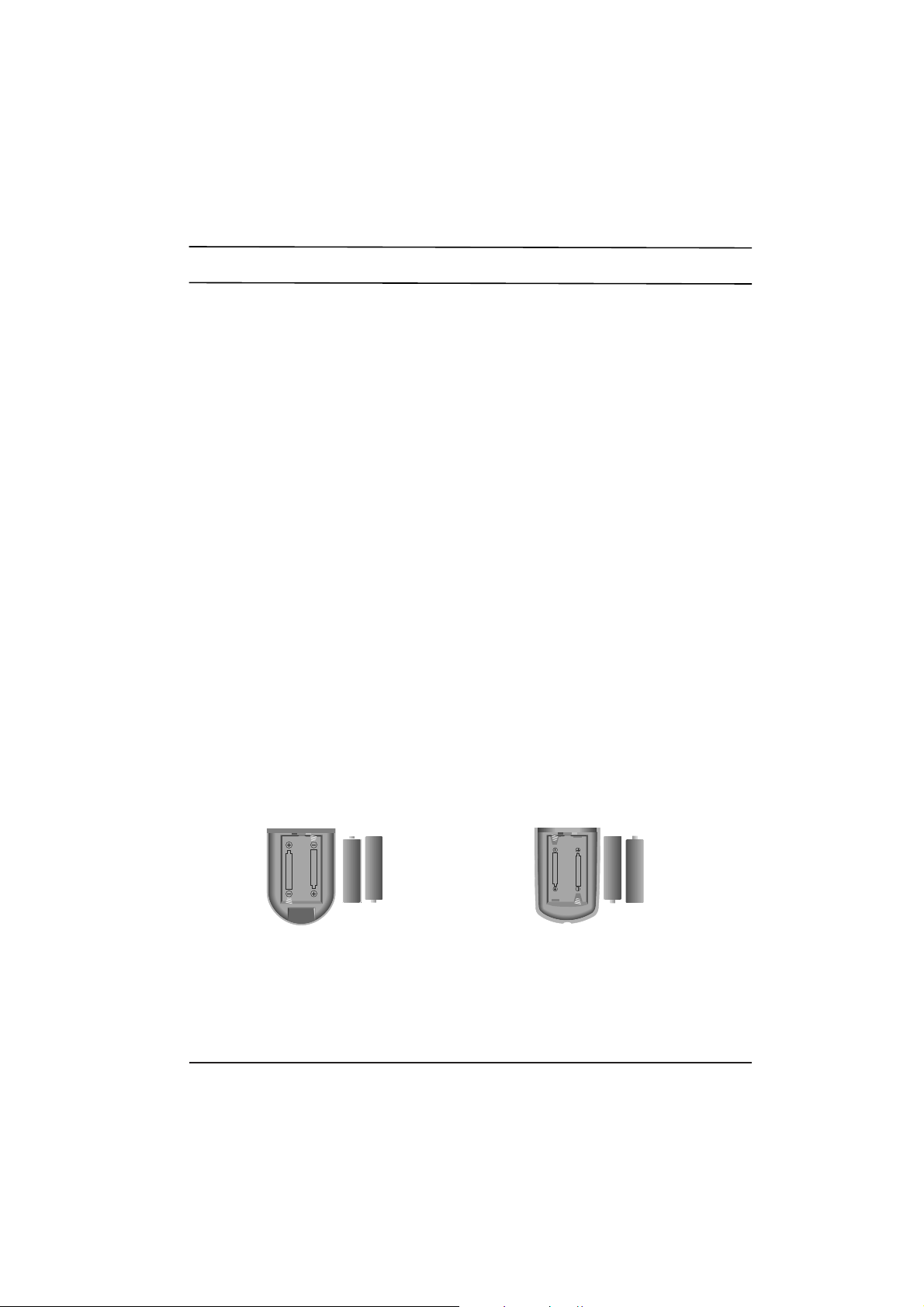
Battery installation
The remote control handset is powered by two AA type batteries. Gently pull down the cover of the
remote control handset until the battery compartment is exposed. Install two batteries as indicated by
the polarity symbols(§]and §^) marked inside the compartment.
Note : To avoid damage from possible battery leakage, remove the batteries if you do not plan to use
the remote control handset for an extended period of time.
Page 2
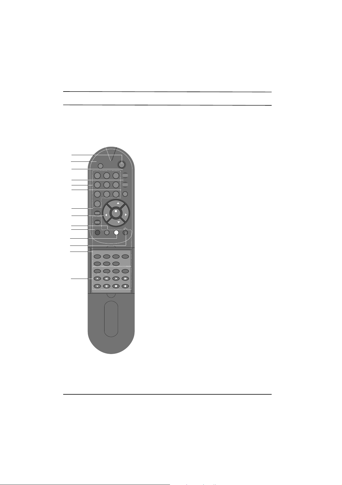
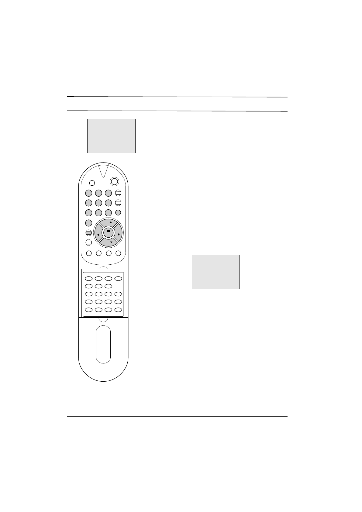
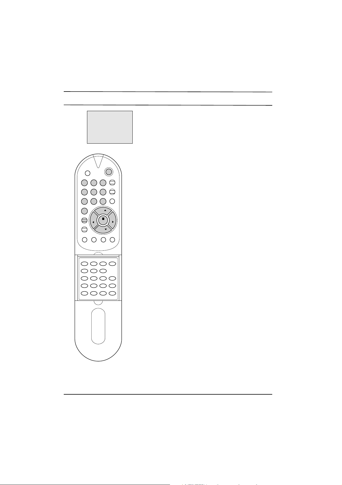
Location and function of controls
All the functions can be controlled with the remote control
handset. Some functions can also be adjusted with the
buttons on the front panel of the set.
Before you use the remote control handset, please install
the batteries.
1. POWER
switches the set on from standby or off to standby.
2. MUTE
switches the sound on or off.
3. PSM (Picture Status Memory)
recalls your preferred picture setting.
4. QUICK VIEW
returns to the previously viewed programme.
5. NUMBER BUTTONS
switch the set on from standby or directly select a
number.
6. TV/AV
selects TV or AV mode.
7. MENU
selects a menu.
8. ¡ª/¡ (Programme Up/Down)
switches the set on from standby.
selects a programme or a menu item.
¢‚/¢” (Volume Down/Up)
adjusts the volume.
adjusts menu settings.
OK
accepts your selection or displays the current mode.
9. UBB (option)
switches the UBB sound on or off.
10. SYSTEM
displays the system selection mode.
1 2 3
4 5 6
7 8 9
0
OK
VOL VOL
REW
PLAY FF
CH P/STILL STOP REC
START LENGTH SP/LP ON/OFF
QSR
TV/AV
MENU
TEXT
UBB
SLEEP
PR
PR
MUTE
POWER
PSM
Q.VIEW
MIX
EXPAND
HOLD UPDATE
TIME REVEAL INDEX
SYSTEM
1
2
3
4
5
6
7
10
8
9
11
12
13
14
(With TELETEXT)
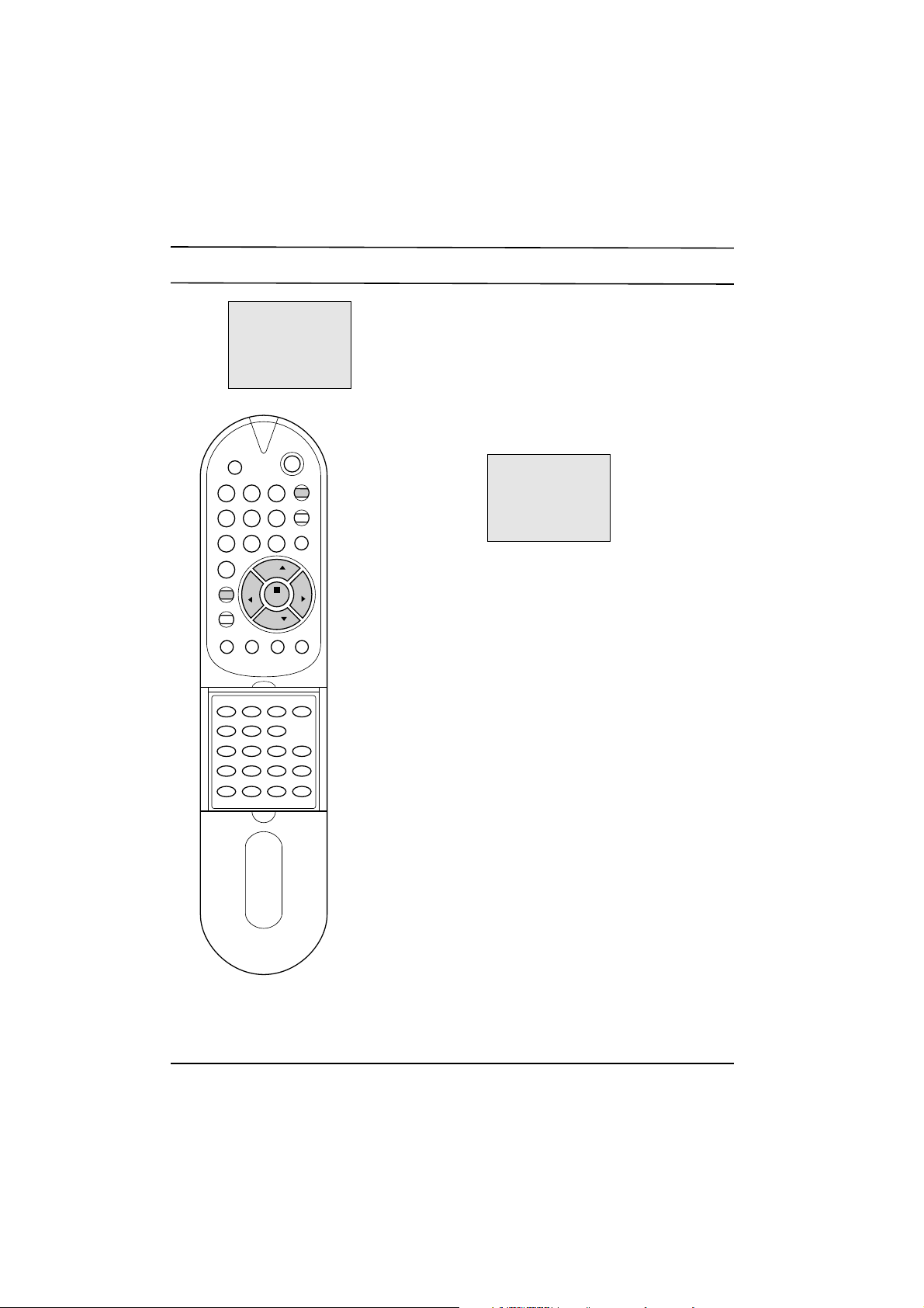
Remote control handset
Page 3
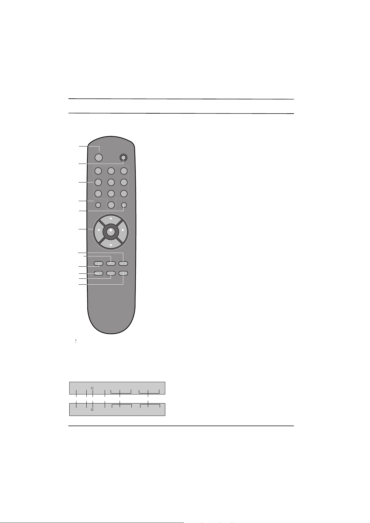
Location and function of controls
11. SLEEP
sets the sleep timer.
12. UNIT
selects single or double digit.
13. TELETEXT BUTTONS (option)
These buttons are used for teletext.
For further details, see the 'Teletext' section.
14. VCR BUTTONS (option)
control the video cassette recorder of our brand.
15. MAIN POWER (vv)
switches the set on or off.
16. STANDBY INDICATOR
illuminates red when the set is in standby mode.
flashes when a button on the remote control handset
is pressed.
17. REMOTE CONTROL SENSOR
18. KARAOKE (option)
These controls are used for karaoke function.
See the 'Karaoke' section.
Remote control handset
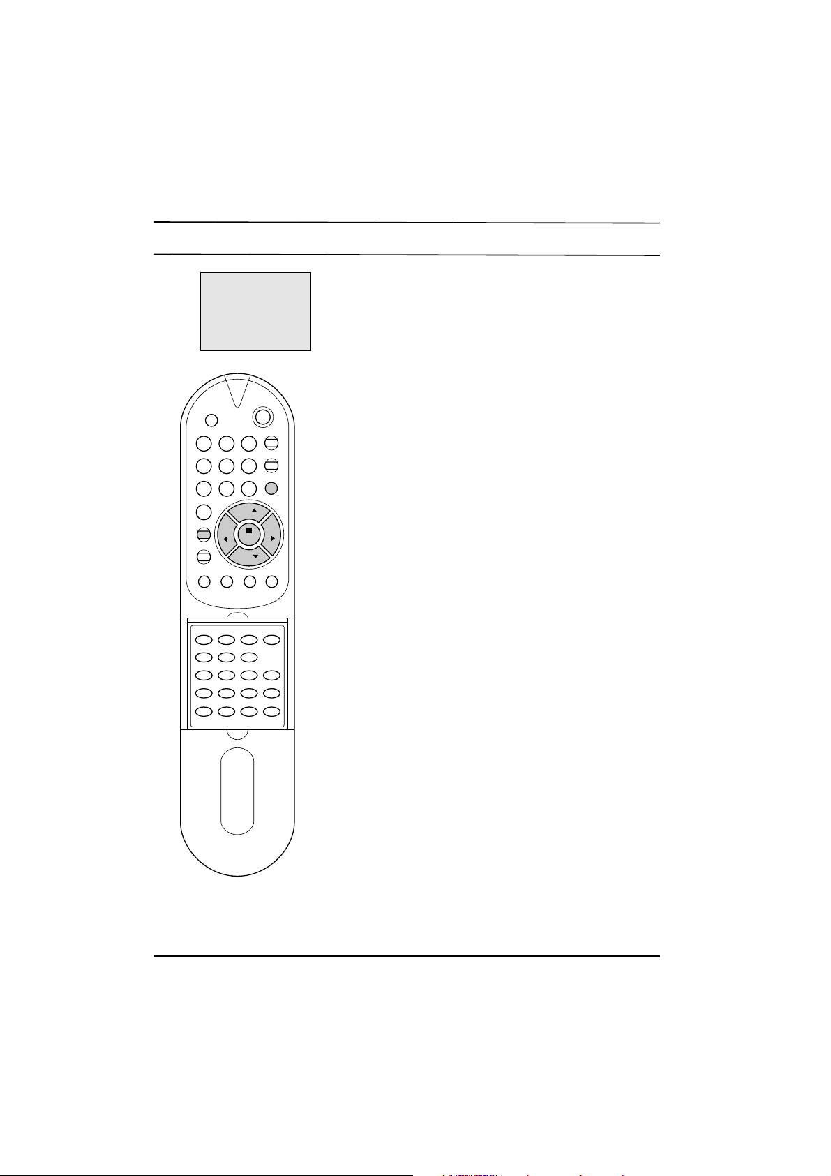
Front panel
Shown is a simplified representation of
front panel. Here shown may be somewhat
different from your set.
1 2 3
4 5 6
7 8 9
0
OK
PR
PR
MENU
PSM
UBBQ.VIEW
SLEEP
POWER
MUTE
¤ :
VOL VOL
TV/AV
SYSTEM
-/--
(Without TELETEXT)
1
2
5
12
10
8
3
7
6
11
4
9
POWER r MENU OK ¢‚VOL¢” ¡ PR¡ª M.VOL ECHO MIC
POWER r MENU OK -VOL+-PR+ M.VOL ECHO MIC
15 1617 7 8 18
Page 4

Basic operation
On and off
1. Press the main power button to switch the set on.
2. If the set is in standby mode, press the POWER, ¡ª/¡ , TV/AV
or NUMBER buttons on the remote control handset to switch it
on fully.
3. Press the POWER button on the remote control handset.
The set reverts to standby mode.
4. Press the main power button again to switch the set off.
Note : If, while the set is switched on, the mains plug is disconnected the set will switch to standby when the mains plug is
replaced in the mains power socket.
Programme selection
You can select a programme number with the ¡ª/¡ or NUMBER
buttons.
Before entering double digit programme numbers, press the -/--
button until the display __ appears on the screen.
Volume adjustment
Press the ¢‚/¢”button to adjust the volume.
Mute function
Press the MUTE button. The sound is switched off and the display
WW
appears. You can cancel it by pressing the MUTE or ¢‚/¢”
button.
Quick view
Press the Q.VIEW button to view the last programme you were
watching.
On screen language selection (option)
This is an optional function. In the models which have on screen
language function, the menu can be displayed on the screen in the
desired language. First select your language.
1. Repeatedly press the MENU button to select MENU 3.
2. Press the ¡ª/¡ button to select LANGUAGE.
3. Press the OK button to display the sub menu.
4. Press the ¡ª/¡ button to select the desired language.
All the on screen displays will appear in the selected language.
5. Press the MENU button repeatedly or TV/AV button once to
return to normal TV viewing.
1 2 3
4 5 6
7 8 9
0
VOL VOL
TV/AV
PR
PR
MUTE
POWER
MENU
TEXT
ON/OFF
MIX
EXPAND HOLD UPDATE MODE
TIME REVEAL INDEX
CH+ REW
PLAY FF
CH- P/STILL STOP REC
START LENGTH SP/LP
QSR
UBB
SLEEP
PSM
Q.VIEW
OK
Page 5
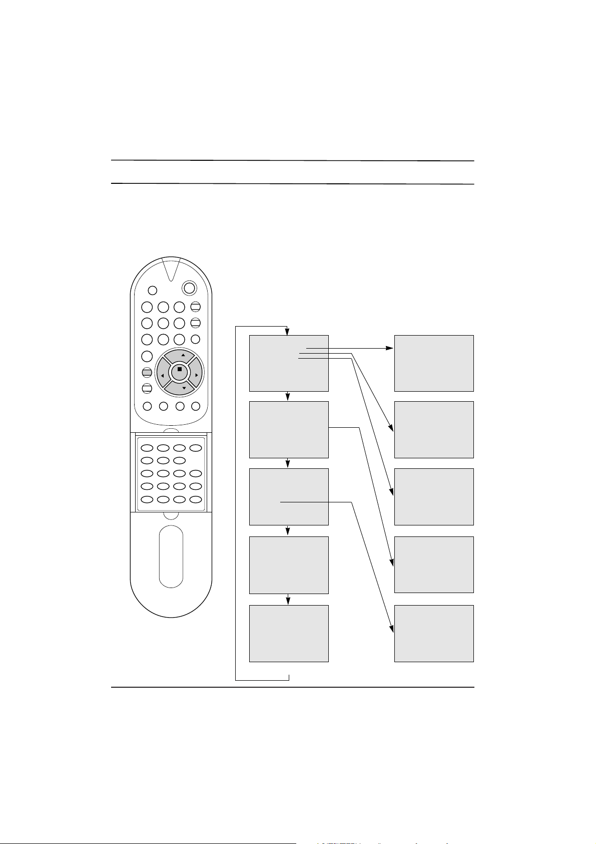
On screen menus
The dialogue between you and your set takes place on screen with an operator
menu. The buttons required for the operating steps are also displayed.
Menu selection
1. Repeatedly press the MENU button to display each menu.
2. Press the ¡ª/¡ button to select a menu item.
The selected menu item changes from green to purple.
3. Press the ¢‚/¢” button to change the setting of a menu item or OK
button to display the sub menu.
Note :
a. The menus automatically disappear in about 12 seconds if you do not
press a button.
b. In the AV mode, MENU 1 is not displayed.
c. In the teletext mode, MENUs are not displayed.
d. In some models, the menu item
LANGUAGE
is also displayed on the
screen in MENU 3.
e. In some models, the menu item
TETRIS
is also displayed on the
screen in MENU 3.
1 2 3
4 5 6
7 8 9
0
VOL VOL
TV/AV
PR
PR
MUTE
POWER
MENU
TEXT
ON/OFF
MIX
EXPAND HOLD UPDATE MODE
TIME REVEAL INDEX
CH+ REW
PLAY FF
CH- P/STILL STOP REC
START LENGTH SP/LP
QSR
UBB
SLEEP
PSM
Q.VIEW
OK
MANUALOPROGRAM
AUTO OPROGRAM
PROGRAMOEDIT
()OOKOMENU
‚O80OCONTRAST
'O60OBRIGHTNESS
·O50OCOLOROOOOOOOO
≥O50OSHARPNESS
O
¥¥¥¥¥¥¥¥¥¥¥¥....
()O}{OOKOMENU
OOOOOOOOOO
INPUTOOOOOOTV
CHILDOLOCKOOFF
AUTOOSLEEPOOFF
SYSTEMOOOOOOOOOO
()OOKOMENU
MENU 1
MENU 2
MENU 3
MENU 4
TV programme
VHF_LOOOOOOOOOOO1
¥...............
MENU
PROGRAMOOOOOOOO1
FINEOOOOOOOOO{{{
SEARCHOOOOOOO{{{
BANDOOOOOOOVHF_L
¥..............
()O}{O0_9OOKOMENU
PR.OOO1OOOPR.OO__
SKIPOOOOOO OOOOOFF
()O}{O0_9OOKOMENU
FAVORITEO1
FAVORITEO2
()OOKOMENU
<
>
CLOCKOOOOOO__:__OO
OFFOTIMEOOO__:__O
ONOOTIMEOOO__:__OO
ONOOPR.OOOOO1
()O}{O0_9OOKOMENU
AUTO
PAL
SECAM
NTSC4.43
NTSC3.58
()OOKOMENU
Page 6
Setting up TV stations
Up to 80 or 100 TV stations can be stored in this set by programme numbers
(0 to 79 or 99). Once you have preset the stations, you will be able to use the
¡ª/¡ or NUMBER buttons to scan the stations you programmed.
Stations can be tuned using an automatic or a manual mode.
Auto programme tuning
All stations that can be received are stored by this method. It is recommended that
you use auto programme during installation of this set.
1. Press the MENU button to select MENU 1.
2. Press the ¡ª/¡ button to select AUTO PROGRAM.
3. Press the OK button to begin auto programming.
The band automatically changes
VHF-L ¤AVHF-H ¤AUHF.
When auto programming is completed, the station stored into pro-gramme
number 1 will appear on the screen.
To stop auto programming, press the MENU button. The active station at
that time will be displayed.
Note : Some undesired stations may be stored, such as noisy or unclear
signals from distant transmitters. You can easily skip these stations by
entering
PROGRAM EDIT
mode.
Manual programme tuning
Manual programme lets you manually tune and arrange the stations in
whatever order you desire.
1. Press the MENU button to select MENU 1.
2. Press the ¡ª/¡ button to select MANUAL PROGRAM.
3. Press the OK button to display the MANUAL PROGRAM mode.
4. Press the ¡ª/¡ button to select PROGRAM. Select the desired
programme number with the ¢‚/¢” or NUMBER buttons.
5. Press the ¡ª/¡ button to select BAND. Press the ¢‚/¢” button to
select VHF-L, VHF-H or UHF as required.
6. Press the ¡ª/¡ button to select SEARCH. Press the ¢‚/¢” button to
commence searching. To stop the search at any time press the MENU
or ¡ª/¡ button.
7. If this station is the one required store it with the OK button, if not press
the ¢‚/¢” button again.
8. To store another station repeat steps 4 to 7.
9. Press the MENU button repeatedly or TV/AV button once to return to
normal TV viewing.
Fine tuning
Normally fine tuning is only necessary if reception is poor.
1. Repeat steps 1 to 3 above.
2. Press the ¡ª/¡ button to select FINE.
3. Press the ¢‚/¢” button to fine tune for the best picture and sound. If
the ¢” button is pressed, the display {{{ will appear. And if the ¢‚
button is pressed, the display }}} will appear.
4. Press the OK button to store the new setting. The display STORED will
appear.
5. Press the MENU button repeatedly or TV/AV button once to return to
normal TV viewing.
The finely tuned programme will be indicated by yellow number during
programme selection.
VOL VOL
TV/AV
PR
PR
MUTE
POWER
MENU
TEXT
ON/OFF
MIX
EXPAND HOLD UPDATE MODE
TIME REVEAL INDEX
CH+ REW
PLAY FF
CH- P/STILL STOP REC
START LENGTH SP/LP
QSR
UBB
SLEEP
PSM
Q.VIEW
1 2 3
4 5 6
7 8 9
0
OK
MENU 1
MANUALOPROGRAM
AUTO OPROGRAM
PROGRAMOEDIT
()OOKOMENU
PROGRAMOOOOOOOO1
FINEOOOOOOOOO{{{
SEARCHOOOOOOO{{{
BANDOOOOOOOVHF_L
¥..............
()O}{O0_9OOKOMENU
Page 7

Setting up TV stations
Programme edit
This function enables you to rearrange the programmes stored by
auto programming in whatever order you desire. Also you can skip
particular programme numbers stored by auto programming.
1. Press the MENU button to select MENU 1.
2. Press the ¡ª/¡ button to select PROGRAM EDIT.
3. Press the OK button, and the PROGRAM EDIT mode will
appear.
Exchanging programmes
1. Press the ¢‚/¢” button to change the left hand programme
number. The viewing station corresponding to the new programme number is shown on the screen.
2. Press the NUMBER buttons to enter the desired right hand
programme number. Any number under 10 is entered with a
numeric '0' in front of it, i.e. '05' for 5.
3. Press the OK button. The station stored in the right hand
programme number will now appear as the left hand
programme number.
4. Repeat steps 1 to 3 to exchange other programmes.
Skipping the stored programme
1. Press the ¢‚/¢” button to select the programme you want to
skip. The viewing station corresponding to the selected
programme number is shown on the screen.
2. Press the ¡ª/¡ button to select SKIP.
3. Press the ¢‚/¢”button to select ON or OFF.
If you select ON, the selected station is skipped.
4. Press the OK button. The display STORED will appear.
5. Press the ¡ª/¡ button to select first menu item then repeat
steps 1 to 4 to skip another programme.
The selection of the skipped programme numbers with the
NUMBER buttons is still possible and they will be indicated by cyan
numbers during programme selection.
Note : You cannot skip the programme number 1.
Press the MENU button repeatedly or TV/AV button once to return
to normal TV viewing.
VOL VOL
TV/AV
PR
PR
MUTE
POWER
MENU
TEXT
ON/OFF
MIX
EXPAND HOLD UPDATE MODE
TIME REVEAL INDEX
CH+ REW
PLAY FF
CH- P/STILL STOP REC
START LENGTH SP/LP
QSR
UBB
SLEEP
PSM
Q.VIEW
1 2 3
4 5 6
7 8 9
0
OK
MENU 1
MANUALOPROGRAM
AUTO OPROGRAM
PROGRAMOEDIT
()OOKOMENU
PR.OOO1OOOPR.OO__
SKIPOOOOOO OOOOOFF
()O}{O0_9OOKOMENU
<
>
Page 8
Picture adjustment
You can adjust picture contrast, brightness, colour intensity,
sharpness and tint (NTSC input only) to the levels you prefer.
1. Repeatedly press the MENU button to select MENU 2.
2. Press the ¡ª/¡ button to select the desired picture item.
3. Press the ¢‚/¢”button to make appropriate adjustments.
At this point you can complete your adjustments or store your
setting for immediate recall by following steps 4 to 6.
4. Press the OK button.
5. Select FAVORITE 1 or FAVORITE 2 with the ¡ª/¡ button.
The FAVORITE 1 or FAVORITE 2 options allow you to
programme two entirely different picture settings for various
lighting conditions such as day and night.
6. Press the OK button. The display STORED will appear.
To recall your preferred setting, press the PSM button until the
desired picture (STANDARD, FAVORITE 1 or FAVORITE 2)
appears. The STANDARD picture is programmed for good picture
reproduction at the factory and cannot be changed.
1 2 3
4 5 6
7 8 9
0
VOL VOL
PR
PR
MUTE
POWER
MENU
TEXT
ON/OFF
MIX
EXPAND HOLD UPDATE MODE
TIME REVEAL INDEX
CH+ REW
PLAY FF
CH- P/STILL STOP REC
START LENGTH SP/LP
QSR
SLEEP
PSM
Q.VIEW
OK
MENU 2
‚O80OCONTRAST
'O60OBRIGHTNESS
·O50OCOLOROOOOOOOO
≥O50OSHARPNESS
O
¥¥¥¥¥¥¥¥¥¥¥¥....
()O}{OOKOMENU
FAVORITEO1
FAVORITEO2
()OOKOMENU
Page 9
Other functions
TETRIS game (option)
In the set with TETRIS function, the set can be used TETRIS
game. You can enjoy the TETRIS game with this set. To make a
good score, try to pile up bricks neatly without leaving empty
spaces.
1. Repeatedly press the MENU button to select MENU 3.
2. Press the ¡ª/¡ button to select TETRIS.
3. Press the OK button to display the TETRIS mode.
4. Select and adjust SPEED (1 to 9), LEVEL (1 to 5) or MODE (0 to
1) with the ¡ª/¡ and ¢‚/¢” button. As the background of
TETRIS game mode, the TV reception mode in MODE 0 and
the muted picture in MODE 1 will appear.
5. Select START with the ¡ª/¡ button then press the OK button
to start the game.
6. Rotate bricks with the OK button, move them to left or right
direction with the ¢‚/¢” button, and set them down straightly
with the ¡ button when playing the game. The game score will
automatically be displayed.
If you want to exit this mode while the game is being played
press the TV/AV button.
7. When the game is finished, select EXIT with the ¡ª/¡ button if
you want to exit the TETRIS game. If not, select START.
8. Press the OK button.
TV and AV modes
Inputs can be set for TV or AV mode. AV mode is used when a video
cassette recorder (VCR), or other equipment is connected to the set.
Note : When a VCR is connected via the aerial socket the set is used
in TV mode. See the 'Connection of external equipment' section.
1. Repeatedly press the MENU button to select MENU 3.
2. Press the ¡ª/¡ button to select INPUT.
3. Press the ¢‚/¢”button to select TV or AV.
4. Press the OK button.
Alternatively you can select the TV or AV mode by pressing the
TV/AV button.
Child lock
The TV can be set so that the remote control handset is needed to
control it. This feature can be used to prevent unauthorised viewing.
1. Repeatedly press the MENU button to select MENU 3.
2. Press the ¡ª/¡ button to select CHILD LOCK.
3. Press the ¢‚/¢”button on the remote control handset to select ON.
4. Press the OK button to return to normal TV viewing.
With the lock on, the display CHILD LOCK ON appears on the screen
if any button on the front panel is pressed while viewing the TV.
Auto sleep
If you select AUTO SLEEP ON the set will automatically switch
itself to standby mode approximately ten minutes after a TV station
stops broadcasting.
1. Repeatedly press the MENU button to select MENU 3.
2. Press the ¡ª/¡ button to select AUTO SLEEP.
3. Press the ¢‚/¢”button to select ON.
4. Press the OK button to return to normal TV viewing.
VOL VOL
TV/AV
PR
PR
MUTE
POWER
MENU
TEXT
ON/OFF
MIX
EXPAND HOLD UPDATE MODE
TIME REVEAL INDEX
CH+ REW
PLAY FF
CH- P/STILL STOP REC
START LENGTH SP/LP
QSR
UBB
SLEEP
PSM
Q.VIEW
OK
MENU 3
OOOOOOOOO
INPUTOOOOOOTV
CHILDOLOCKOOFF
AUTOOSLEEPOOFF
SYSTEMOOOOOOOOOO
() OOKOMENU
Page 10
Other functions
Colour system setting
This set is adjusted for the main TV system in your area. Under
normal circumstances, select AUTO. If necessary (if input signal is
weak, colour and sound are poor), change the colour system by
using the instructions below.
1. Repeatedly press the MENU button to select MENU 3.
2. Press the ¡ª/¡ button to select SYSTEM .
3. Press the OK button to display the sub menu .
4. Press the ¡ª/¡ button to select the correct colour system.
5. Press the OK button to store the setting. The display STORED
will appear.
You can directly display the system selection mode by pressing the
SYSTEM button. And then repeat steps 4 to 5 above.
Note :
a. If you adjusted the system as shown steps above, the colour
system appears in cyan when the current mode is displayed by
pressing the OK button.
b. The colour system which the set cannot receive could be
selected but not operated.
Sleep timer
You don't have to remember to switch the set off before you go to
sleep. The sleep timer automatically switches the set to standby
after the preset time elapses.
For selecting your desired number of minutes, press the SLEEP
button several times or continuously. --- will appear on the screen,
followed by 120, 90, 60, 30, 20 and 10.
The timer begins to count down from the number of minutes selected.
Note :
a. To view the remaining sleep time, press the SLEEP button once.
b. To cancel the sleep time, repeatedly press the SLEEP button
until the display
SLEEP---
appears.
c. When you switch the set off, the set releases the preset sleep time.
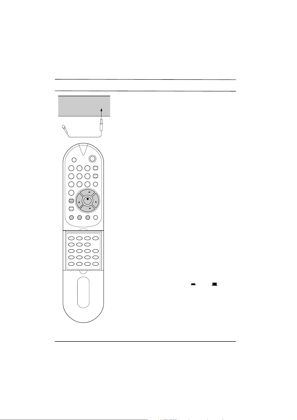
Karaoke (option)
In the set with karaoke function, the set can be used as a karaoke
monitor by connecting a microphone (not supplied) and using a
VCR or VDP etc.
1. Connect a microphone (¥ 6.3 mm) to the MIC socket on the
front panel.
2. Switch the microphone on.
3. Turn the M.VOL knob clockwise to increase the microphone
volume or counterclockwise to decrease.
4. Press the ECHO button to switch on ( ) or off ( ) the echo
effect function.
Note : When a microphone connected to the set is moved too close to
the set, high-pitched feedback may be heard. Then, move the
microphone further from the set or decrease the microphone volume.
UBB sound (option)
In the set with UBB function, the set can be used UBB sound. Only
a set with UBB sound option can perform this function. UBB (Ultra
Bass Booster) sound stresses and emphasizes heavy sound.
Press the UBB button to switch on or off the UBB sound. The display UBB ON or UBB OFF will appear.
1 2 3
4 5 6
7 8 9
0
VOL VOL
PR
PR
MUTE
POWER
MENU
TEXT
ON/OFF
MIX
EXPAND HOLD UPDATE MODE
TIME REVEAL INDEX
CH+ REW
PLAY FF
CH- P/STILL STOP REC
START LENGTH SP/LP
QSR
SLEEP
PSM
Q.VIEW
OK
UBB
SYSTEM
M.VOL ECHO
MIC
Page 11
Time setting
Clock
The clock uses the 24 hour system, and must be set to the correct
time before operating the set. You must set the clock correctly
before using on/off time functions.
1. Repeatedly press the MENU button to select MENU 4.
2. Press the ¡ª/¡ button to select CLOCK.
3. Adjust hour and minute with the ¢‚/¢” button or NUMBER
buttons.
4. Press the OK button to return to normal TV viewing.
Off time
The set automatically switches off at the preset time.
1. Repeatedly press the MENU button to select MENU 4.
2. Press the ¡ª/¡ button to select OFF TIME .
3. Adjust hour and minute with the ¢‚/¢” button or NUMBER
buttons.
4. Press the OK button to return to normal TV viewing.
On time
The set automatically switches on at the preset time and station.
1. Repeatedly press the MENU button to select MENU 4.
2. Press the ¡ª/¡ button to select ON TIME.
3. Adjust hour and minute with the ¢‚/¢” button or NUMBER
buttons.
4. Press the ¡ª/¡ button to select ON PR. then press the ¢‚/¢”
button or NUMBER buttons to select the desired programme
number.
5. Press the OK button to return to normal TV viewing.
Note :
a. In the event of power interruption (disconnection or power
failure), the clock, on time and off time must be reset.
b. If the same time is set for the on time and the off time, only the
off time operates.
c. This set must be put into standby mode with the POWER button
on the remote control handset to operate the on time function.
d. If the on time function activates, the TV will automatically switch
to the on time programme number, even during viewing.
e. Two hours after the set is turned on by the on time function it
will automatically switch back to standby mode unless a button
has been pressed.
f. Once the on or off time is set, these functions operate daily at
the preset time.
TV/AVTV/AV
VOL VOL
PR
PR
MUTE
POWER
MENU
TEXT
ON/OFF
MIX
EXPAND HOLD UPDATE MODE
TIME REVEAL INDEX
CH+ REW
PLAY FF
CH- P/STILL STOP REC
START LENGTH SP/LP
QSR
UBB
SLEEP
PSM
Q.VIEW
1 2 3
4 5 6
7 8 9
0
OK
CLOCKOOOOOO__:__OO
OFFOTIMEOOO__:__O
ONOOTIMEOOO__:__OO
ONOOPR.OOOOO1
()O}{O0_9OOKOMENU
MENU 4
Page 12
Teletext (option)
Teletext is an optional function, therefore only a set with the
teletext system can receive the teletext broadcast.
Teletext is a free service broadcast by most TV stations which
gives up-to-the-minute information on news, weather, television
programmes, share prices and many other topics.
The teletext decoder of this TV can support the Simple, TOP and
FASTEXT systems. Simple mode consists of a number of pages which
are selected by directly entering the corresponding page number. TOP
and FASTEXT are more modern methods allowing quick and easy
selection of teletext information.
Switch on/off
Press the TEXT button to switch to teletext. The initial page or last
selected page appears on the screen.
Two page numbers, TV station name, date and time are displayed
on the screen headline. The first page number indicates your
selection, while the second shows the current page displayed.
Press the TEXT or TV/AV button to switch off teletext. The previous
mode reappears.
Simple mode
Page selection
1. Enter the desired page number as a three digit number with the
NUMBER buttons. If during selection you press a wrong
number, you must complete the three digit number and then reenter the correct page number.
2. The ¡ª/¡ button can be used to select the preceding or
following page.
TOP mode
The user guide displays four fields-red, green, yellow and blue at
the bottom of the screen. The yellow field denotes the next group
and the blue field indicates the next block.
Block/group/page selection
1. With the BLUE button you can progress from block to block.
2. Use the YELLOW button to proceed to the next group with
automatic overflow to the next block.
3. With the GREEN button you can proceed to the next existing
page with automatic overflow to the next group. Alternatively the
¡ªbutton can be used.
4. The RED button permits to return to previous selection. Alternatively
the ¡ button can be used.
Direct page selection
Corresponding to the Simple mode, you can select a page by
entering it as a three digit number using the NUMBER buttons in
TOP mode.
FASTEXT mode
The teletext pages are colour coded along the bottom of the screen
and are selected by pressing the corresponding coloured button.
Page selection
1. Press the INDEX button to select the index page.
2. You can select the pages which are colour coded along the
bottom line with the same coloured buttons.
3. Corresponding to the Simple mode, you can select a page by
entering its three digit page number with the NUMBER buttons
in FASTEXT mode.
4. The ¡ª/¡ button can be used to select the preceding or
following page.
OK
VOL VOL
TV/AV
PR
PR
MUTE
POWER
MENU
TEXT
ON/OFF
MIX
EXPAND HOLD UPDATE
TIME REVEAL INDEX
CH+ REW
PLAY FF
CH- P/STILL STOP REC
START LENGTH SP/LP
QSR
UBB
SLEEP
PSM
Q.VIEW
1 2 3
4 5 6
7 8 9
0
Page 13
Teletext (option)
Special teletext functions
REVEAL
Press this button to display concealed information, such as
solutions of riddles or puzzles.
Press this button again to remove the information from the display.
EXPAND
Selects double height text.
Press this button to enlarge the top half of the page.
Press this button again to enlarge the bottom half of the page.
Press this button again to return to the normal display.
UPDATE
Displays the TV picture on the screen while waiting for the new
teletext page. The display will appear at the top left hand
corner of the screen. When the updated page is available then
display will change to the page number.
Press this button to view the updated teletext page.
HOLD
Stops the automatic page change which will occur if a teletext page
consists of 2 or more sub pages. The number of sub pages and the
sub page displayed is, usually, shown on the screen below the
time. When this button is pressed the stop symbol is displayed at
the top left-hand corner of the screen and the automatic page
change is inhibited.
To continue press this button again.
MIX
Displays the teletext pages superimposed on the TV picture.
To switch the TV picture off press this button again.
TIME
When viewing a TV programme, press this button to display the
time at the top right hand corner of the screen. Press this button
again to remove the display. In the teletext mode, press this button
to select a sub page number. The sub page number is displayed at
the bottom of the screen. To hold or change the sub page, press
the RED/GREEN, ¡ª/¡ or NUMBER buttons. Press again to exit
this function.
1 2 3
4 5 6
7 8 9
0
VOL VOL
TV/AV
PR
PR
MUTE
POWER
MENU
TEXT
ON/OFF
INDEX
CH+ REW
PLAY FF
CH- P/STILL STOP REC
START LENGTH SP/LP
QSR
UBB
SLEEP
PSM
Q.VIEW
MIX
EXPAND
HOLD UPDATE
TIME REVEAL
Page 14
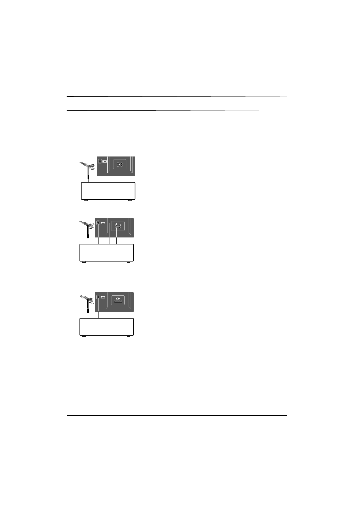
Connection of external equipment
You can connect additional equipment, such as VCRs, camcorders
etc. to your set. Here shown may be somewhat different from your
set.
Aerial socket
1. Connect the RF out socket of the VCR to the aerial socket on
the back of the set.
2. Connect the aerial cable to the RF aerial in socket of the VCR.
3. Store the VCR channel on a desired programme number using
the 'Manual programme tuning' section.
4. Select the programme number where the VCR channel is stored.
5. Press the PLAY button on the VCR.
Audio/Video in/out sockets
1. Connect the audio/video out sockets of the VCR to audio/video
in sockets of the set and in sockets of the VCR to out sockets of
the set.
2. Press the TV/AV button to select AV.
3. Press the PLAY button on the VCR.
The VCR playback picture appears on the screen.
You can also record programmes received by the TV on video
tape via audio/video out sockets.
Euro scart socket
If your set has the Euro scart socket,
1. Connect the euro scart socket of the VCR to the Euro scart
socket of the set.
2. Press the PLAY button on the VCR.
If your VCR outputs a switching voltage the set will switch to AV
mode automatically.
Otherwise, press the TV/AV button on the remote control
handset to select AV. The VCR playback picture appears on
the screen.
VCR
75Ω
OUT
AUDIO
IN
OUT
VIDEO
IN
VCR
75Ω
OUT
AUDIO
IN
OUT
VIDEO
IN
VCR
75Ω
Page 15
Troubleshooting check list
The mains plug-(plugged in and
switched on)
Is the TV switched on
Try another channel (weak signal)
Check aerial (plugged into TV?)
Check aerial (broken lead?)
Check aerial
Check for local interference
Adjust contrast
Adjust brightness
Adjust colour
Adjust volume
Check the batteries in remote control
Check Audio/Video sockets (VCR only)
Check these items and try to
adjust these
Symptoms
No picture, no sound
Sound OK, poor picture
Picture OK, poor sound
Picture blurred
Lines or streaks in picture
Poor reception on some channels
No colour
Poor colour
Remote control does not work
Page 16
Troubleshooting Guide
DEAD SET
(NO RASTER/NO SOUND)
Check +B voltage at J131
112V(or 118V)
0V
Check the heater elements
of CPT are lighting or not
No
Check/Replace FR423
Yes
Check the voltage at
C430(+)
0.1V
Check/Replace IC430
R430, IC401, D411, FR422
0.1V
Check/Replace IC501
8V
Check the voltage
at pin21 of IC501
over 0.4V
Check/Replace IC01
(IC202, IC01T, IC02T:
in case of with TXT)
Check the rectified voltage
of main power at C817(+)
0V
Check/Replace
F801, DB813, R821, T801
150~380V
Check the voltage
at pin9 of IC802
Lower than 6V
Check/Replace
D810, ZD810, Q810
6~8V
Check/Replace
IC802, D806, D811.
Check the secondary
voltage are short
Page 17

NO PICTURE/NO SOUND
Check the voltage of
TUNER MB(12V)
Check/Replace
Tuner
Check the tuning
condition
Check the 33V at C416(+)
Check/Replace
R421, ZD404
Check/Replace
FR422, D411, IC401
(RASTER OK)
11.8~ 12.2V
0V
Page 18

NO RASTER(SOUND OK)
Check heater elements of
CRT are lighting
Check the AC voltage at
H/T pin of CPT SOCKET
on CPT board
Check/Replace
CPT
Check/Replace
FR423, 420
The screen is
blinking
Check replace
IC501
Readjust White
Balance
Check the 180V
line at C418(+)
Check/Replace
D413
Retrace line
is visible
Check the screen voltage (G2)
alignment is correct or not
Check the screen colour
Check the base voltage
of Q901-Q903
Check/Replace
D901~ D903
Check/Replace
R918-920 or
soldering
condition on
CPT board.
No
Yes
Abnormal
White
Abnormal
R/G/B
Normal
12V 4~ 5V
6.0~ 6.5Vrms
0Vrms
Page 19

NO SOUND(PICTURE OK)
Check the voltage(SMPS 25V)
at pin5 of IC601
Check/Replace of
FR804, D804
Check the soldering
state around IC601
Check/Replace
IC01
Check/Replace IC430
Check/Replace IC601
Check the voltage at
pin16 of IC501
Check/Replace Q508
(TV/AV, TXT switch)
Check the voltage
at pin 10 of IC501
Check the voltage
at pin 5 of IC501
Check whether the
voltage is swing or not at
pin3 of IC01 when turning
the volume up
Check/Replce IC01
Abnormal
Abnormal
Normal(20~ 27V)
10~12V
Normal
7~9V
0V
Page 20

NO COLOR
Check the frequency(4.43/3.58MHz)
at pin 34.35 of IC501
Check/Replace
X501, 502
Check/Replace
IC501
Check/Replace
IC01
Check/Replace
IC501
Check/Replace
IC503
Check/Replace
IC502
Check the voltage
of PIN27 of IC501.
Check whether the voltage is swing
or not at the pin5 of IC01 according to
changing colour up/down
Check whether R-Y and B-Y are
out from pin30 and pin31 of IC501
Check whether R-Y and B-Y are
out from pin9 and pin10 of IC503
Check whether R-Y and B-Y are
out from pin11 and pin12 of IC502
Check wheter R/G/B is out from
pin20, pin19 and pin18 of IC501
Check/Replace
IC501
Abnormal
Abnormal
Swing
Swing
Yes
Yes
No
Below 5V
Not
Not
No
No
Normal
Page 21

NO TELETEXT
Check the voltage 12V at C403(+)
Check the 12V line
to be correct
Check/Replace
IC04T
Check/Replace
Q21T
- Check/Replace
IC01T, IC02T
µ-COM(IC01)
- Check all the connections
of SDA SCL
Check the voltage of
C21T(+)
Check video signal is
normal at the pin3 of
IC01T
Check I2C Bus (SDA, SCL)
Check/Replace X01T
Abnormal
Abnormal
Normal
4.8~ 5.2V
Yes
Yes
NO
NO
Page 22

ADJUSTMENT INSTRUCTIONS
* Safety precautions
1. It is safe to adjust after using insulating transformer
between the power supply line and chassis input to
prevent the risk of electric shock and protect the
instrument.
2.Never disconnect leads while the TV receiver is on.
3. Don't short any portion of circuits while power is on.
4. The adjustment must be done by the correct appliances.
But this is changeable in view of productivity.
5. Unless otherwise noted, set the line voltage to 220Vac+_
20%, 50/60Hz.
* Test Equipment required
1. Swee p Generator
2. Marker Generator(38.0MHz: Picture/32.5MHz: Sound)
3. Alignmen t Scope(5121A)
4. Patter n Generator(PAL/SECAM)
5. DC Power Supply
6.Color analyzer
7.Multimeter(Volt meter)
Preparation for VCO Adjustment
1. Connect the measuring equipment to the TV as shown in
Fig. 1
2. Set RF output level of Sweep Generator to 90dBuV.
* VCO (Voltage Controlled Oscillator)
Adjustment
Test Point : JP4(L504)
Adjust : VL501
1) Turn on DC power supplies.
2) Adjust VCO ADJ.
Carrier (PC) may be at the lowest position as shown Fig.
2.
Fig. 2: Output waveform on Alignment Scope
NOTE: When performing this adjustment, if there are 2
adjusted point in VL501, select the lower core
position.
coil(L501)so that the level of Picture
SC (Sound Carrier)
: 32.5 MHz
PC (Picture Carrier)
: 38.0 MHz
MAIN BOARD
C533
(JP 3)
J9
AGC
ADJ.
RF
out
SWEEP S.G
with Marker
CK
0.01uF
TUNER
Z101
(JP 1)
Hor
Ver
5
VL501
VCO ADJ.
48
Alignment
Scope
IC501
7
L504
(JP 4)
3.3K
DC POWER
SUPPLY
5.0 +0.1V
Fig. 1: Connection Diagram of Equipment for VCO Adjustment
IC401
1
(JP 6)
DC POWER
SUPPLY
16 +0.5V
* RF AGC (Auto Gain Control)
Adjustment
Test Point :
Adjust : VR501
The RF AGC control VR501 was aligned at the time of
manufacture for optimum performance over a wide range
conditions. Readjust
unless unusual local conditions exist, such as;
1)Channel interference in a CATV system
2)Picture bending and/or color beats, which are unusually
due to excessive RF signal input when the reciever is
too close to a transmitting tower or when the receiver
is connected to an antenna distribution system where
the RF signal has been amplified.
In this case, the input signal should be attenuated(with
pad or filter) to a satisfactory level.
Picture noise caused by "broadcast noise" or weak
3)
signal.
If the broadcast is "clean" and the RF signal is at least
1mV (60dBu), the picture will be noise free in any area.
J9(AGC ADJ.) or Observing Display
VR501 should not be necessary
- 1-
Page 23

Adjusting the VR501(RF AGC)control to one end of
rotation will usually cause a relatively poor signal to noise
ratio;
Adjusting to the other end of rotation will usually cause a
degradation of over load capabilities resulting on color
beats or adjacent channel interference.
For the best results, adju
performing on all other local channels, or Refer to the
following Table 1.
st VR501contol while
* Screen & White Balance
(color temperatur e) Adjustment
NOTE:
1. This adjustment should be performed after
warming up for 20 minutes.
2.The color bias controls (VR901, VR902, VR903)
affect the low light (dark) area of the picture
while the color drive controls (VR904, VR905)
affect the high light (white) areas.
Tuner P/N
113-118C/D/F
113-238H
6700VMV001A
Maker
LG-ALPS
LG-ALPS
SANYO
Adjustment Voltage
5.7+_0.1Vdc
6.0+_0.1Vdc
4.9+_0.1Vdc
<Table 1>
REMARK
0+_1dBuV
RF 6
RF 60+_1dBuV
RF 60+_1dBuV
* Vertical Height, Center Adjustment
Test Poin t:Observing display
Adjust : VR301(Vertical Height)
VR302 (Vertical Center)
1) Tune the TV set to receive a digital test pattern.
2) Set standard picture mode(contrast: 80, bright :60,
color: 50).
3)Adjust the Vertical height co
circle of a digital test pattern may be located within
the effective screen of the CPT.
4) Adjust the Vertical center
obtaining geometric center of valuable display
vertically.
ntrol (VR301)so that the
control (VR302)for
1) Set all the controls (VR901-VR905) on CPT Board to
geometric center position.
Set the standard mode (contrast : 80, bright : 60, color : 50).
2)
3) Set the AV mode, adjust and set the screen volume of
FBT at just cut-off position(No AV input signal).
4)Set the TV mode, tune the TV set to receive white
pattern.
By using color analyzer (white balance checker), adjust
5)
X position equals to
+_8, it means that color temperature is 10,000+_800 at
low light (4.
5ftL) and high light (over 45ftL).
281+_8 and Y position equals to 288
* Focus Adjustment
NOTE: This adjustment should be performed after
warming up for 10 minutes.
Test Poin t: Observing display
Adjust : Focus control of FBT
1) Tune the TV set to receive a digital test pattern.
2)Adjust the Focus control for the best overall focus.
* Horizontal Center Adjustment
Test Poin t: Observing display
Adjust : VR502
1) Tune the TV set to receive a PAL digital pattern.
2) Adjust the Horizontal center co
obtaining geometric center of valubale display
horizontally.
ntrol(VR502)for
- 2-
Page 24

PURITY & CONVERGENCE ADJUSTMENT
Caution:
Convergence and Purity have been factory aligned. Do not
attempt to tamper with these alignments.
However, the effects of adjacent receiver components, or
replacement of picture tube or deflection yoke may require the
need to readjust purity any convergence.
DEFLECTION YOKE
PURITY &CONVERGENCE
MAGNET ASSEMBLY
6-POLE
,,,
RUBBER
WEDGES
,,
,,
,,,
PURITY MAGNET
4-POLE
GLASS CLOTH TAPE
X-AXIS YOKE
POSITIONING
(L/R PURITY)
5.Reconnect the internal degaussing coil.
6. Position the beam bender locking rings at the 9 o'clock
position and the other three pairs of tabs (2,4 and 6 pole
magnets) at the 12 o'clock position.
6-POLE
6-POLE
MAGNETS
4-POLE
MAGNET
MAGNES
CONVERGENCE MAGNET ASSEMBLY
CONVERGENCE MAGNET ASSEMBLY
PURITY MAGNET(2-POLE)
* Purity Adjustment
This procedure DOES NOT apply to bonded yoke and picture
tube assemblies.
The instrument should be at room temperature (60 degrees F or
above) for six (6) hours and be operating at low beam current
(dark background) for approximately 20 to 30 minutes before
performing purity adjustments.
CAUTION:Do not remove any trim magnets that may be
attached to the bell of the picture tube.
1. Remove the AC power and disconnect the internal
degaussing coil.
2. Remove the yoke from the neck of the picture tube.
3. If the yoke has the tape version beam bender, remove it and
replace it with a adjustable type beam bender (follow the
instructions provided with the new beam bender)
4. Replace the yoke on the picture tube neck, temporarily
remove the three (3) rubber wedges from the bell of the
picture tube and then slide the yoke completely forward.
7. Perform the following steps, in the order given, to prepare the
receiver for the purity adjustment procedure.
a. Face the receiver in the "magnetic north" direction.
b. Externally degauss the receiver screen with the television
power turned off.
c. Turn the television on for approximately 10 seconds to
perform internal degaussing and then turn the TV off.
d. Unplug the internal degaussing coil. This allows the
thermistor to cool down while you are performing the purity
adjustment. DO NOT MOVE THE RECEIVER FROM ITS
"MAGNETIC NORTH" POSITION.
e. Turn the receiver on and obtain a red raster by increasing
the red bias control (CW) and decreasing the bias controls
for the remaining two colors (CCW).
f. Attach two round magnets on the picture tube screen at 3
o'clock and 9 o'clock positions, approximately one (1) inch
from the edge of the mask (use double-sided tape).
3-2
Page 25

1.ADJUST YOKE Z-AXIS FIRST
TO GET EQUAL BLUE
COLOR CIRCLES
MAGNETS
RED RED
2 .ADJUST BEAM BENDER 2 POLE
MAGNET TO GET FOUR EQUAL
COLOR CIRCLES
8. Referring to above, perform the following two steps:
a. Adjust the yoke Z-axis to obtain equal blue circles.
b. Adjust the appropriate beam bender tabs to obtain correct
purity (four equal circles).
9. After correct purity is set, tighten the yoke clamp screw and
remove the two screen magnets.
10.Remove the AC power and rotate the receiver 180 degrees
(facing "magnetic south").
11. Reconnect the internal degaussing coil.
12. Turn the receiver on for 10 seconds (make sure the receiver
came on) to perform internal degaussing, and then turn the
receiver off.
13. Unplug the internal degaussing coil.
14. Turn on the receiver and check the purity by holding one (1)
round magnet at the 3 o'clock and a second round magnet at
9 o'clock position. If purity is not satisfactory, repeat steps 8
through 14.
15. Turn off the receiver and reconnect the internal degaussing
coil.
* Convergence Adjustment
Caution:This procedure DOES NOT apply to bonded yoke and
picture tube assemblies.
Do not use screen magnets during this adjustment
procedure. Use of screen magnets will cause an
incorrect display.
1. Remove AC power and disconnect the internal degaussing
coil.
2. Apply AC Power and set the brightness to the Picture Reset
condition. Set the Color control to minimum.
3. Apply 8V to the pin.
6. Reconnect the internal degaussing coil and apply AC power.
7. Turn the receiver on for 10 seconds to perform internal
degaussing and then turn the receiver off again.
8. Unplug the internal degaussing-coil.
9. Turn on the receiver, connect a signal generator to the VHF
antenna terminal and apply a crosshatch signal.
Caution:During the convergence adjustment procedure, be
very careful not to disturb the purity adjustment tabs
are accidentally move, purity should be confirmed
before proceeding with the convergence adjustments.
Note:
Make sure the focus is set correctly on this instrument
before proceeding with the following adjustment.
10. Converge the red and blue vertical lines to the green vertical
line at the center of the screen by performing the following
steps (below TABLE).
a. Carefully rotate both tabs of the 4-pole ring magnet
simultaneously in opposite directions from the 12 o'clock
position to converge the red and blue vertical lines.
b. Carefully rotate both tabs of the 6-pole ring magnet
simultaneously in opposite directions form the 12 o'clock
position to converge the red and blue (now purple)
vertical lines with the green vertical line.
11. Converge the red and blue horizontal with the green line at
the center of the screen by performing the following steps.
(below TABLE)
a. Carefully rotate both tabs of the 4-pole ring magnet
simultaneously in the same direction (keep the spacing
between the two tabs the same) to converge the red and
blue horizontal lines.
b. Carefully rotate both tabs of the 6-pole ring magnet
simultaneously in same direction (keep the spacing
between the two tabs the same) to converge the red and
blue (now purple) horizontal lines with the green
horizontal line.
c. Secure the tabs previsouly adjusted by locking them in
place with the locking tabs on the beam bender.
4. Adjust the Red, Green and Blue Bias controls to get a dim
white line.
5. Remove the AC power and 8V from the pin.
3-3
Page 26

3-4
RING
PAIRS
4
POLE
ROTATION DIRECTION
OF BOTH TABS
OPPOSITE
SAME
OPPOSITE
SAME
MOVEMENT OF RED
AND BLUE BEAMS
B B
RR
OR
OR
B R B R
OR
B
R
B
R
B R
OR
B
R
6
POLE
12. While watching the 6 o'clock positions on the screen, rock the
front of the yoke in a vertical (up/down) direction to converge
the red and blue vertical lines. (Fig upper left)
13. Temporarily place a rubber wedge at the 12 o'clock position
to hold the vertical position or the yoke.
14.
Check the 3 o'clock and 9 o'clock areas to confirm that the red
and blue horizontal lines are converged.
If the lines are not converged, slightly offset the vertical tilt of the
yoke (move the rubber wedge if necessary) to equally balance the
convergence error of the horizontal lines at 3 o'clock and 9 o'clock
and the vertical lines at 6 o'clock and 12 o'clock.
15. Place a 1.5 inch piece of glass tape over the rubber foot at
the rear of the 12 o'clock wedge.
16. While watching the 6 o'clock and 12 o'clock areas of the
screen, rock the front of the yoke in the horizontal (left to
right) motion to converge the red and blue horizontal lines.
(Fig. upper right)
17. Temporarily place a rubber wedge at the 5 o'clock and 7
o'clock positions to hold the horizontal position of the yoke.
18. Check the 3 o'clock and 9 o'clock areas to confirm that the
red and blue vertical lines are converged. If the lines are not
converged, slightly offset the horizontal tilt of the yoke (move
the temporary rubber wedges if necessary) to equally
balance the convergence error of the horizontal lines at 6
o'clock and 12 o'clock and the vertical lines at 3 o'clock and 9
o'clock.
19. Using a round magnet confirm purity at the center, right and
left sides and corners. See Purity Adjustment Procedure.
20. Reconfirm convergence and apply a 1.5 inch piece of glass
tape over the rubber foot at the rear of the 5 o'clock and the 7
o'clock wedges.
RED
BLUE
RED BLUE
BLUE
RED
GREEN
GREEN
BLUE RED
GREEN
GREEN
ADJUSTMENT
VIEWING
AREA
UP/DOWN ROCKING OF THE YOKE
CAUSES OPPOSITE ROTATION OF RED
AND BLUE RASTERS
ADJUSTMENT
VIEWING
AREA
RED
RED
GREEN
TV
SCREEN
LEET/RIGHT ROCKING OF THE YOKE
CAUSES OPPOSITE SIZE CHANGE OF
THE RED AND BLUE RASTERS
UP/DOWN ROCKING OF THE YOKE
CAUSES OPPOSITE ROTATION OF RED
AND BLUE RASTERS
LEFT/RIGHT ROCKING OF THE YOKE
CAUSES OPPOSITE SIZE CHANGE OF THE
RED AND BLUE RASTERS
Page 27

- 16 -
100
200
200-01
200-02
200-03
200-05
300-01
301
300
200-04
OPTION
OPTION
400
400-01
302
100-01
100-02
100-03
100-04
100-05
100-06
100-07
100-08
100-09
500
1 2 3
4 5 6
7 8 9
0
OK
PR
PR
MENU
PSM
UBBQ.VIEW
SLEEP
POWER
MUTE
VOL VOL
TV/AV
SYSTEM
-/--
EXPLODED VIEW
Page 28

- 17 -
EXPLODED VIEW PARTS LIST
LOCA. NO PART NO DESCRIPTIONS
100 300-B81Y CABINET ASSY KCA14A86 HXLRG7
100-01 441-494A BUTTON, POWER
100-02 320-070G SPRING, COIL
100-03 316-410C WINDOW, FILTER
100-04 454-027A INDICATOR, PRE-AMP
100-05 313-263Y PANEL ASSY, CONTROL
100-06 314-284B GRILL, SPEAKER
100-07 441-308A BUTTON,CONTROL
100-08 120-D04C SPEAKER C072P(8 OHM)
100-09 341-745B HOLDER, PCB
200 2055-00781U CPT A34KVK02XX 00S7ND(-0.5G)
200-01 341-721A HOLDER, D-COIL (FOR AUTO.L=65)
200-02 332-057B SCREW ASSY,HEXAGON HEAD
200-03 150-D02B COIL, DEGAUSSING,CU 14Ó 42T 5.7OHM
200-04 170-A01A LEAD SET,CPT EARTH(14Ó)
200-05 341-721B HOLDER, D-COIL (FOR AUTO.L=130)
300 6871VMM071A PWB ASSY,MAIN (64A) 4ANSNPBREN
6871VMM071U PWB ASSY, MAIN(64A)4ANHNPBREN, MT-RK
300-01 341-783A HOLDER, LED
301 303-F62A COVER, TUNER
302 174-222A CORD ASSY, POWER(174-219A,L=220)
400 303-H59A COVER ASSY,BACK(A/V-IN-OUT)
400-01 1PPF0403116 SCREW,PAN HEAD D4 L16
500 105-230M REMOTE CONTROLLER MC-64A,W/O TXT,LG
105-230D TRANSMITTER MC64A W/O TXT, G/S
The components identified by shading and
mark are critical for safety.
Replace only with part number specified.
The parts which are marked with "ƒN" are
Local parts.
ƒN
ƒN
ƒN
ƒN
ƒN
Page 29

REPLACEMENT PARTS LIST
- 18 -
The components identified by shading and
mark are critical for safety.
Replace only with part number specified.
LOCA. NO PART NO DESCRIPTION
IC01
IC02
IC03
IC201
IC301
IC401
IC430
IC501
IC502
IC601
IC801
IC802
IC840
DB813
D01
D101
D301
D401
D406
D408
D410
D411
D413
D415
D416
D501
D601
D801
D805
D806
D809
D810
D811
D812
D901
D902
D903
LD01
ZD01
ZD02
ZD03
ZD401
ZD402
ZD404
ZD551
ZD801
ZD810
Q01
0IGS863415D
0IAL240210A
0IKE704200B
0ISA722200A
0ISA783300A
0IKE781200C
0IKE780800A
0IPH836255B
0IPH466500B
0ISG200600A
0ITF435000A
0ISK570700A
0IKE780500K
0DD260000BD
0DD414809ED
0DD414809ED
0DD400509AA
0DD414809ED
0DD060009AC
0DD414809ED
0DD060009AC
0DD150009CA
0DD060009AC
0DD414809ED
0DD414809ED
0DD414809ED
0DD414809ED
0DD150009CA
0DD060009AC
0DD560009AA
0DD100009AM
0DD100009AM
0DD060009AC
0DD060009AC
0DD414809ED
0DD414809ED
0DD414809ED
0DD000000BA
0DZ750009AA
0DZ750009AA
0DZ750009AA
0DZ910009BA
0DZ510009AB
0DZ330009BA
0DZ510009AB
0DZ910009BA
0DZ750009AA
0TR126609AA
IC,LG8634-15D
IC,AT24C02-10PC 8D EEPROM(2K,IIC)
IC,KIA7042P 3P 4.2V RESET
IC,LA7222 (1280 AUDIO)
IC,LA7833 7SIP V/OUT 2.2A(P-P)
IC,KIA7812PI 3P(TO-220IS) 12V,1A
IC,KIA7808PI 3P(TO-220IS) 1A,8V
IC,TDA8362B/N5 52SD P/N/S 1CHIP
IC,TDA4665-V4 16D 1H D/L(TAIWAN)
IC,TDA2006,SOUND
IC,4N35(G)V 6D PHOTO COUPLER
IC,STR/S5707(LF.953) 9P SMPS-CNTR
IC,KIA7805PI 3P(TO-220IS) 5V,1A
DIODE BRIDGE D2SBA60
DIODE DS4148
DIODE DS4148
DIODE 1N4005 GP
DIODE DS4148
DIODE TVR06J 0.6A/600V 250NS
DIODE DS4148
DIODE TVR06J 0.6A/600V 250NS
DIODE RGP15J
DIODE TVR06J 0.6A/600V 250NS
DIODE DS4148
DIODE DS4148
DIODE DS4148
DIODE DS4148
DIODE RGP15J
DIODE TVR06J 0.6A/600V 250NS
DIODE BYT56M TEMIC TP TEMIC
DIODE EU1ZV
DIODE EU1ZV
DIODE TVR06J 0.6A/600V 250NS
DIODE TVR06J 0.6A/600V 250NS
DIODE DS4148
DIODE DS4148
DIODE DS4148
DIODE LAMP(DIFFUSION TYPE)
DIODE ZENER MTZ7.5B
DIODE ZENER MTZ7.5B
DIODE ZENER MTZ7.5B
DIODE ZENER MTZ9.1B
DIODE ZENER MTZ5.1B
DIODE ZENER HZT33
DIODE ZENER MTZ5.1B
DIODE ZENER MTZ9.1B
DIODE ZENER MTZ7.5B
TRANSISTOR KTA1266-TP-Y (KTA1015)
LOCA. NO PART NO DESCRIPTION
Q02
Q101
Q102
Q180
Q181
Q182
Q201
Q202
Q220
Q301
Q302
Q303
Q401
Q402
Q503
Q508
Q512
Q513
Q514
Q515
Q517
Q601
Q802
Q803
Q804
Q810
Q901
Q902
Q903
C01
C02
C03
C04
C05
C06
C08
C09
C10
C103
C11
C111
C112
C113
C12
C13
C14
C16
C17
C181
C182
C183
0TR319809AA
0TR319809AB
0TR319709AB
0TR126609AA
0TR126609AA
0TR126609AA
0TR126609AA
0TR319809AA
0TR319809AA
0TR319809AA
0TR319809AA
0TR319809AA
0TR102609AA
0TR525000AA
0TR126609AA
0TR102009AB
0TR126609AA
0TR126609AA
0TR126609AA
0TR319809AA
0TR126609AA
0TR102009AB
0TR320209AA
0TR319809AB
0TR319809AA
0TR102609AA
0TR322900AA
0TR322900AA
0TR322900AA
0CN1030F679
0CN4710K519
0CN3910K519
0CQ4731N509
0CN1010K519
0CN2710K519
0CC2200K415
0CC2200K415
0CC1500K415
0CQ1041N509
0CC1000K115
0CN1030F679
0CN1030F679
0CN1030F679
0CN1030F679
0CE335DK618
0CE475DK618
0CN1030F679
0CQ1041N509
0CE475DK618
0CE475DK618
0CQ1041N509
TRANSISTOR KTC3198-TP-Y (KTC1815)
TRANSISTOR KTC3198-TP-GR (KTC1815)
TRANSISTOR KTC3197,TP(KTC388A)
TRANSISTOR KTA1266-TP-Y (KTA1015)
TRANSISTOR KTA1266-TP-Y (KTA1015)
TRANSISTOR KTA1266-TP-Y (KTA1015)
TRANSISTOR KTA1266-TP-Y (KTA1015)
TRANSISTOR KTC3198-TP-Y (KTC1815)
TRANSISTOR KTC3198-TP-Y (KTC1815)
TRANSISTOR KTC3198-TP-Y (KTC1815)
TRANSISTOR KTC3198-TP-Y (KTC1815)
TRANSISTOR KTC3198-TP-Y (KTC1815)
TRANSISTOR KTC1026-Y TP(KTC2230A)
TRANSISTOR 2SC5250 TO-3PFM
TRANSISTOR KTA1266-TP-Y (KTA1015)
TRANSISTOR KRC102M,TP(KRC1202)
TRANSISTOR KTA1266-TP-Y (KTA1015)
TRANSISTOR KTA1266-TP-Y (KTA1015)
TRANSISTOR KTA1266-TP-Y (KTA1015)
TRANSISTOR KTC3198-TP-Y (KTC1815)
TRANSISTOR KTA1266-TP-Y (KTA1015)
TRANSISTOR KRC102M,TP(KRC1202)
TRANSISTOR KTC3202-TP-Y (KTC1959)
TRANSISTOR KTC3198-TP-GR (KTC1815)
TRANSISTOR KTC3198-TP-Y (KTC1815)
TRANSISTOR KTC1026-Y TP(KTC2230A)
TRANSISTOR KTC3229 (KTC2068)
TRANSISTOR KTC3229 (KTC2068)
TRANSISTOR KTC3229 (KTC2068)
C,TUBULA(HIGH DIELE) 0.01MF 16V M
C,TUBULA(HIGH DIELE) 470PF 50V K
C,TUBULA(HIGH DIELE) 390P 50V K
C,POLYESTER(MYLAR) 0.047U 100V K
C,TUBULA(HIGH DIELE) 100PF 50V K
C,TUBULA(HIGH DIELE) 270PF 50V K
C,CERAMIC(TEMP COMP) 22P 50V J
C,CERAMIC(TEMP COMP) 22P 50V J
C,CERAMIC(TEMP COMP) 15P 50V J
C,POLYESTER(MYLAR) 0.1MF 100V L
C,CERAMIC(TEMP COMP) 10PF 50V D
C,TUBULA(HIGH DIELE) 0.01MF 16V M
C,TUBULA(HIGH DIELE) 0.01MF 16V M
C,TUBULA(HIGH DIELE) 0.01MF 16V M
C,TUBULA(HIGH DIELE) 0.01MF 16V M
C,ELECTROLYTIC 3.3UF STD 50V M
C,ELECTROLYTIC 4.7UF STD 50V M
C,TUBULA(HIGH DIELE) 0.01MF 16V M
C,POLYESTER(MYLAR) 0.1MF 100V L
C,ELECTROLYTIC 4.7UF STD 50V M
C,ELECTROLYTIC 4.7UF STD 50V M
C,POLYESTER(MYLAR) 0.1MF 100V L
ICs
DIODES
CAPACITORS
TRANSISTORS
Page 30

- 19 -
The components identified by shading and
mark are critical for safety.
Replace only with part number specified.
LOCA. NO PART NO DESCRIPTION
C184
C185
C186
C187
C188
C189
C20
C203
C21
C218
C219
C22
C220
C221
C222
C223
C224
C226
C227
C228
C23
C301
C303
C304
C305
C306
C308
C310
C311
C312
C314
C402
C403
C404
C407
C408
C409
C411
C412
C413
C414
C416
C418
C419
C420
C421
C422
C430
C501
C502
C503
0CQ1042K439
0CE475DK618
0CE106DF618
0CE337DF618
0CE107DF618
0CN1030F679
0CN2210K519
0CE107DF618
0CN1010K519
0CE227DD618
0CE226DF618
0CN1010K519
0CE106DF618
0CE106DF618
0CN1030F679
0CE107DF618
0CE106DF618
0CE106DF618
0CQ1021N509
0CE107DD618
0CN1010K519
0CN3310K519
0CC5600K415
0CQ1021N509
0CE227DJ618
0CQ6831N509
181-0322
0CQ1041N509
0CE476DF618
0CQ1041N509
0CE108DH618
0CQ1531N509
0CE227DF618
0CE225DK618
0CE475DP618
0CE105DP618
0CQ3931N509
0CK4710W515
0CE108DJ618
0CK4710W515
0CE337DH618
0CE475DK618
0CE1061R618
0CK4710W515
181-013H
181-015E
181-009V
0CE227DD618
0CQ2721N409
0CX1000K409
0CN1030F679
C,POLYESTER(MYLAR) 0.1UF S 50V J
C,ELECTROLYTIC 4.7UF STD 50V M
C,ELECTROLYTIC 10UF STD 16V M
C,ELECTROLYTIC 330UF STD 16V M
C,ELECTROLYTIC 100UF STD 16V M
C,TUBULA(HIGH DIELE) 0.01MF 16V M
C,TUBULA(HIGH DIELE) 220PF 50V K
C,ELECTROLYTIC 100UF STD 16V M
C,TUBULA(HIGH DIELE) 100PF 50V K
C,ELECTROLYTIC 220UF STD 10V M
C,ELECTROLYTIC 22UF STD 16V M
C,TUBULA(HIGH DIELE) 100PF 50V K
C,ELECTROLYTIC 10UF STD 16V M
C,ELECTROLYTIC 10UF STD 16V M
C,TUBULA(HIGH DIELE) 0.01MF 16V M
C,ELECTROLYTIC 100UF STD 16V M
C,ELECTROLYTIC 10UF STD 16V M
C,ELECTROLYTIC 10UF STD 16V M
C,POLYESTER(MYLAR) 0.001U 100V K
C,ELECTROLYTIC 100UF STD 10V M
C,TUBULA(HIGH DIELE) 100PF 50V K
C,TUBULA(HIGH DIELE) 330P 50V K
C,CERAMIC(TEMP COMP) 56P 50V J
C,POLYESTER(MYLAR) 0.001U 100V K
C,ELECTROLYTIC 220UF STD 35V M
C,POLYESTER(MYLAR) 0.068U 100V K
C,TANTAL 2.2MF 25V K
C,POLYESTER(MYLAR) 0.1MF 100V L
C,ELECTROLYTIC 47UF STD 16V M
C,POLYESTER(MYLAR) 0.1MF 100V L
C,ELECTROLYTIC 1000UF STD 25V M
C,POLYESTER(MYLAR) 0.015MF 100V K
C,ELECTROLYTIC 220UF STD 16V M
C,ELECTROLYTIC 2.2UF STD 50V M
C,ELECTROLYTIC 4.7000UF STD 160V M
C,ELECTROLYTIC 1UF STD 160V M
C,POLYESTER(MYLAR) 0.039UF 100V K
C,CERAMIC(HIGH DIELE) 470PF 500V K
C,ELECTROLYTIC 1000UF STD 35V M
C,CERAMIC(HIGH DIELE) 470PF 500V K
C,ELECTROLYTIC 330UF STD 25V M
C,ELECTROLYTIC 4.7UF STD 50V M
C,ELECTROLYTIC 10M SM 250V M
C,CERAMIC(HIGH DIELE) 470PF 500V K
C,MPP 200V 0.62UF J
C,MPP 1600V 0.0068UF H
CAPACITOR PP 200V 0.047UF K
C,ELECTROLYTIC 220UF STD 10V M
C,POLYESTER(MYLAR) 2700PF 100V J
C,TUBULA(T.C) 10P 50V J
C,TUBULA(HIGH DIELE) 0.01MF 16V M
LOCA. NO PART NO DESCRIPTION
C505
C507
C508
C509
C510
C511
C512
C513
C514
C515
C516
C517
C518
C519
C520
C521
C522
C523
C524
C525
C526
C527
C528
C529
C530
C531
C532
C533
C534
C535
C536
C537
C538
C539
C551
C552
C553
C554
C555
C556
C557
C601
C602
C603
C604
C605
C606
C607
C608
C609
C610
C658
0CE106DF618
0CN1040K949
0CN2230H949
0CE107DF618
0CQ1041N509
0CQ1041N509
0CE106DF618
0CQ1042K439
0CE476DF618
0CQ1041N509
0CQ1041N509
0CQ1041N509
0CE476DF618
0CE106DF618
0CE475DK618
0CQ4721N509
0CQ1041N509
0CC1300K415
0CC1300K415
0CN2230H949
0CE476DF618
0CQ4721N509
0CE105DK618
0CQ4721N509
0CQ1041N509
0CN1030F679
0CQ2231N509
0CE225DK618
0CQ1041N509
0CE106DF618
0CE106DF618
0CN2230H949
0CE225DK618
0CQ3321N509
0CE476DF618
0CN2230H949
0CQ1041N509
0CQ1041N509
0CQ1021N509
0CQ1021N509
0CN2230H949
0CE108DJ618
0CQ1031N509
0CE477DF618
0CQ1041N509
0CE225DK618
0CE336DK618
0CQ1031N509
0CE475DK618
0CE475DK618
0CE226DK618
0CN1020K519
C,ELECTROLYTIC 10UF STD 16V M
C,TUBULA(HIGH DIELE) 0.1M 50V Z
C,TUBULA(HIGH DIELE) 22000P 25V Z F
C,ELECTROLYTIC 100UF STD 16V M
C,POLYESTER(MYLAR) 0.1MF 100V L
C,POLYESTER(MYLAR) 0.1MF 100V L
C,ELECTROLYTIC 10UF STD 16V M
C,POLYESTER(MYLAR) 0.1UF S 50V J
C,ELECTROLYTIC 47UF STD 16V M
C,POLYESTER(MYLAR) 0.1MF 100V L
C,POLYESTER(MYLAR) 0.1MF 100V L
C,POLYESTER(MYLAR) 0.1MF 100V L
C,ELECTROLYTIC 47UF STD 16V M
C,ELECTROLYTIC 10UF STD 16V M
C,ELECTROLYTIC 4.7UF STD 50V M
C,POLYESTER(MYLAR) 0.0047U 100V K
C,POLYESTER(MYLAR) 0.1MF 100V L
C,CERAMIC(TEMP COMP) 13P 50V J
C,CERAMIC(TEMP COMP) 13P 50V J
C,TUBULA(HIGH DIELE) 22000P 25V Z F
C,ELECTROLYTIC 47UF STD 16V M
C,POLYESTER(MYLAR) 0.0047U 100V K
C,ELECTROLYTIC 1UF STD 50V M
C,POLYESTER(MYLAR) 0.0047U 100V K
C,POLYESTER(MYLAR) 0.1MF 100V L
C,TUBULA(HIGH DIELE) 0.01MF 16V M
C,POLYESTER(MYLAR) 0.022MF 100V K
C,ELECTROLYTIC 2.2UF STD 50V M
C,POLYESTER(MYLAR) 0.1MF 100V L
C,ELECTROLYTIC 10UF STD 16V M
C,ELECTROLYTIC 10UF STD 16V M
C,TUBULA(HIGH DIELE) 22000P 25V Z F
C,ELECTROLYTIC 2.2UF STD 50V M
C,POLYESTER(MYLAR) 0.0033U 100V K
C,ELECTROLYTIC 47UF STD 16V M
C,TUBULA(HIGH DIELE) 22000P 25V Z F
C,POLYESTER(MYLAR) 0.1MF 100V L
C,POLYESTER(MYLAR) 0.1MF 100V L
C,POLYESTER(MYLAR) 0.001U 100V K
C,POLYESTER(MYLAR) 0.001U 100V K
C,TUBULA(HIGH DIELE) 22000P 25V Z F
C,ELECTROLYTIC 1000UF STD 35V M
C,POLYESTER(MYLAR) 0.01U 100V K
C,ELECTROLYTIC 470UF STD 16V M
C,POLYESTER(MYLAR) 0.1MF 100V L
C,ELECTROLYTIC 2.2UF STD 50V M
C,ELECTROLYTIC 33UF STD 50V M
C,POLYESTER(MYLAR) 0.01U 100V K
C,ELECTROLYTIC 4.7UF STD 50V M
C,ELECTROLYTIC 4.7UF STD 50V M
C,ELECTROLYTIC 22UF STD 50V M
C,TUBULA(HIGH DIELE) 1000PF 50V K
Page 31

- 20 -
The components identified by shading and
mark are critical for safety.
Replace only with part number specified.
LOCA. NO PART NO DESCRIPTION
C664
C665
C667
C804
C805
C810
C811
C812
C813
C814
C817
C818
C819
C820
C822
C823
C824
C825
C826
C827
C828
C830
C832
C833
C834
C835
C840
C841
C901
C902
C903
C904
C905
J103
J106
L01
L103
L103
L181
L402
L403
L501
L504
L653
L654
L802
L803
L804
L805
L901
T402
0CN1030F679
0CX5600K409
0CX4700K409
0CK4710W515
0CE477DJ618
181-120E
0CE475DK618
0CK4710W515
0CK47101515
0CE227DP650
181-001W
0CK47102515
0CK4710W515
0CE227DJ618
0CQZVBK002B
0CN1020K519
0CE475DK618
0CE227DJ618
181-120E
0CE1071P650
0CQZVBK002B
0CE477DF618
0CK10201515
0CK10201515
0CK10201515
0CK10201515
0CE227DD618
0CN1030F679
0CN2710K519
0CN2710K519
0CN3310K519
0CE476DF618
181-033S
0LA0102K119
0LA0102K119
0LA0392K119
0LA0101K119
150-C01D
0LA0331K119
150-L01W
125-022K
0LA1000K119
0LA0331K119
0LA0681K119
0LA0122K119
150-C02F
125-022K
125-123A
125-022K
150-C02A
151-C02H
C,TUBULA(HIGH DIELE) 0.01MF 16V M
C,TUBULA(T.C) 56P 50V J
C,TUBULA(T.C) 47PF 50V J
C,CERAMIC(HIGH DIELE) 470PF 500V K
C,ELECTROLYTIC 470UF STD 35V M
C,ACT 4KV E 222M FL10
C,ELECTROLYTIC 4.7UF STD 50V M
C,CERAMIC(HIGH DIELE) 470PF 500V K
C,CERAMIC 470P 1KV K
C,ELECTROLYTIC 220UF STD 160V M
C,AL.ELECTROLYTIC CE 450V 220UF M
C,CERAMIC(HIGH DIELE) 470P 2KV K
C,CERAMIC(HIGH DIELE) 470PF 500V K
C,ELECTROLYTIC 220UF STD 35V M
C,POLYESTER A.C 275V 0.15UF K
C,TUBULA(HIGH DIELE) 1000PF 50V K
C,ELECTROLYTIC 4.7UF STD 50V M
C,ELECTROLYTIC 220UF STD 35V M
C,ACT 4KV E 222M FL10
C,ELECTROLYTIC 100M SM 160V M
C,POLYESTER A.C 275V 0.15UF K
C,ELECTROLYTIC 470UF STD 16V M
C,CERAMIC(HIGH DIELE) 1000P 1KV K
C,CERAMIC(HIGH DIELE) 1000P 1KV K
C,CERAMIC(HIGH DIELE) 1000P 1KV K
C,CERAMIC(HIGH DIELE) 1000P 1KV K
C,ELECTROLYTIC 220UF STD 10V M
C,TUBULA(HIGH DIELE) 0.01MF 16V M
C,TUBULA(HIGH DIELE) 270PF 50V K
C,TUBULA(HIGH DIELE) 270PF 50V K
C,TUBULA(HIGH DIELE) 330P 50V K
C,ELECTROLYTIC 47UF STD 16V M
CAPACITOR 2KV B 122K TP7.5
INDUCTOR 10UH K
INDUCTOR 10UH K
INDUCTOR 39UH K
INDUCTOR 1.0UH K
COIL, CHOKE 0.55UH A 1105 *HYPER TUNER
INDUCTOR 3.3UH K 2.3*3.4 TP
COIL, H-LINEARITY 57UH
CORE, FERRITE 1UH
INDUCTOR 100UH K
INDUCTOR 3.3UH K 2.3*3.4 TP
INDUCTOR 6.8UH K
INDUCTOR 12UH K
COIL, CHOKE 82UH R1217
CORE, FERRITE 1UH
CORE, FERRITE BFD3565R2F
CORE, FERRITE 1UH
COIL, CHOKE 10UH R0814
TRANSFORMER, H-DRIVE,EI-19,BULK
LOCA. NO PART NO DESCRIPTION
T801
T802
VL501
FR421
FR422
FR423
FR804
FR812
J94
R02
R03
R04
R05
R06
R07
R08
R105
R106
R107
R108
R11
R112
R113
R114
R116
R116
R117
R118
R118
R12
R13
R14
R15
R16
R17
R18
R180
R181
R182
R183
R184
R185
R186
R187
R187
R188
R20
R201
R203
R204
150-F06N
151-B06Q
150-E08N
0RF0101J607
0RF0470J607
180-D02P
0RF0201K607
0RF0470H609
0RD1503F609
0RD2702F609
0RD9101F609
0RD2200F609
0RD0912F609
0RD1001F609
0RD3300F609
0RD4700F609
0RD3302F609
0RD1003F609
0RD3302F609
0RD2402F609
0RD5601F609
0RD2200F609
0RD5101F609
0RD6800F609
0RD0682F609
0RD1200F609
0RD1001F609
0RD0562F609
0RD0392F609
0RD1001F609
0RD1601F609
0RD1201F609
0RD2001F609
0RD3901F609
0RD2201F609
0RD1001F609
0RD4702F609
0RD4702F609
0RD4702F609
0RD3302F609
0RD9102F609
0RD1003F609
0RD1002F609
0RD1802F609
0RD2402F609
0RD1202F609
0RD8201F609
0RD0752F609
0RD3300F609
0RD3300F609
COIL,LINE FILTER SQE2424 7MH
TRANSFORMER, SMPS EER4215 STR-S5707 W
COIL, VAR,07S 1B 38.9MHZ
R,FUSIBLE 1 1W 5%
R,FUSIBLE 0.47 1W 5%
R,RNF RND(S) CR 2W 3.0 J
R,FUSIBLE 2 2W 5%
R,FUSIBLE 0.47 1/2W 5
R,CARBON FILM 150K 1/6W 5
R,CARBON FILM 27K 1/6W 5
R,CARBON FILM 9.1K 1/6W 5
R,CARBON FILM 220 1/6W 5
R,CARBON FILM 91 1/6W 5
R,CARBON FILM 1.0K 1/6W 5
R,CARBON FILM 330 1/6W 5
R,CARBON FILM 470 1/6W 5
R,CARBON FILM 33K 1/6W 5
R,CARBON FILM 100K 1/6W 5
R,CARBON FILM 33K 1/6W 5
R,CARBON FILM 24K 1/6W 5
R,CARBON FILM 5.6K 1/6W 5
R,CARBON FILM 220 1/6W 5
R,CARBON FILM 5.1K 1/6W 5
R,CARBON FILM 680 1/6W 5
R,CARBON FILM 68 1/6W 5
R,CARBON FILM 120 1/6W 5 *HYPER TUNER
R,CARBON FILM 1.0K 1/6W 5
R,CARBON FILM 56 1/6W 5
R,CARBON FILM 39 1/6W 5 *HYPER TUNER
R,CARBON FILM 1.0K 1/6W 5
R,CARBON FILM 1.6K 1/6W 5
R,CARBON FILM 1.2K 1/6W 5
R,CARBON FILM 2.0K 1/6W 5
R,CARBON FILM 3.9K 1/6W 5
R,CARBON FILM 2.2K 1/6W 5
R,CARBON FILM 1.0K 1/6W 5
R,CARBON FILM 47K 1/6W 5
R,CARBON FILM 47K 1/6W 5
R,CARBON FILM 47K 1/6W 5
R,CARBON FILM 33K 1/6W 5
R,CARBON FILM 91K 1/6W 5
R,CARBON FILM 100K 1/6W 5
R,CARBON FILM 10K 1/6W 5
R,CARBON FILM 18K 1/6W 5
R,CARBON FILM 24K 1/6W 5 *HYPER TUNER
R,CARBON FILM 12K 1/6W 5
R,CARBON FILM 8.2K 1/6W 5
R,CARBON FILM 75 1/6W 5
R,CARBON FILM 330 1/6W 5
R,CARBON FILM 330 1/6W 5
RESISTORS
COILS & TRANSFORMERS
Page 32

- 21 -
LOCA. NO PART NO DESCRIPTION
R205
R21
R212
R217
R218
R22
R220
R221
R224
R225
R226
R227
R228
R229
R23
R230
R231
R232
R26
R27
R29
R30
R301
R302
R303
R304
R305
R306
R307
R308
R309
R31
R310
R311
R312
R313
R314
R315
R316
R317
R32
R33
R34
R35
R36
R37
R38
R39
R40
R410
R411
R412
R413
0RD0822F609
0RD2702F609
0RD2202F609
0RD4700F609
0RD3001F609
0RD1502F609
0RD1001F609
0RD1001F609
0RD2001F609
0RD4700F609
0RD1101F609
0RD2001F609
0RD0562F609
0RD3900F609
0RD6801F609
0RD3301F609
0RD6801F609
0RD2200F609
0RD1001F609
0RD4701F609
0RD6802F609
0RD1001F609
0RD6200F609
0RD8200H609
0RD1203F609
0RD0822F609
0RD4700F609
0RD3002F609
0RN2402F409
0RD6800F609
0RD1202F609
0RD1201F609
0RS3300J607
0RD0221H609
0RD3902F609
0RD4702F609
0RD2002F609
0RD4701H609
0RD1002F609
0RD0471H609
0RD3002F609
0RD4702F609
0RD1002F609
0RD2200F609
0RD4701F609
0RD4701F609
0RD4701F609
0RD3301F609
0RD1002F609
0RD3903H609
180-B01U
0RD1202F609
0RS3901J607
R,CARBON FILM 82 1/6W 5
R,CARBON FILM 27K 1/6W 5
R,CARBON FILM 22K 1/6W 5
R,CARBON FILM 470 1/6W 5
R,CARBON FILM 3.0K 1/6W 5
R,CARBON FILM 15K 1/6W 5
R,CARBON FILM 1.0K 1/6W 5
R,CARBON FILM 1.0K 1/6W 5
R,CARBON FILM 2.0K 1/6W 5
R,CARBON FILM 470 1/6W 5
R,CARBON FILM 1.1K 1/6W 5
R,CARBON FILM 2.0K 1/6W 5
R,CARBON FILM 56 1/6W 5
R,CARBON FILM 390 1/6W 5
R,CARBON FILM 6.8K 1/6W 5
R,CARBON FILM 3.3K 1/6W 5
R,CARBON FILM 6.8K 1/6W 5
R,CARBON FILM 220 1/6W 5
R,CARBON FILM 1.0K 1/6W 5
R,CARBON FILM 4.7K 1/6W 5
R,CARBON FILM 68K 1/6W 5
R,CARBON FILM 1.0K 1/6W 5
R,CARBON FILM 620 1/6W 5
R,CARBON FILM 820 1/2W 5
R,CARBON FILM 120K 1/6W 5
R,CARBON FILM 82 1/6W 5
R,CARBON FILM 470 1/6W 5
R,CARBON FILM 30K 1/6W 5
R,METAL FILM 24K 1/6W 1% TA52
R,CARBON FILM 680 1/6W 5
R,CARBON FILM 12K 1/6W 5
R,CARBON FILM 1.2K 1/6W 5
R,METAL FILM OXIDE 330 1W 5%
R,CARBON FILM 2.2 1/2W 5
R,CARBON FILM 39K 1/6W 5
R,CARBON FILM 47K 1/6W 5
R,CARBON FILM 20K 1/6W 5
R,CARBON FILM 4.7K 1/2W 5
R,CARBON FILM 10K 1/6W 5
R,CARBON FILM 4.7 1/2W 5
R,CARBON FILM 30K 1/6W 5
R,CARBON FILM 47K 1/6W 5
R,CARBON FILM 10K 1/6W 5
R,CARBON FILM 220 1/6W 5
R,CARBON FILM 4.7K 1/6W 5
R,CARBON FILM 4.7K 1/6W 5
R,CARBON FILM 4.7K 1/6W 5
R,CARBON FILM 3.3K 1/6W 5
R,CARBON FILM 10K 1/6W 5
R,METAL FILM OXIDE 390K 1/2W 5
R,CEMENT RS RECT S 5W 4.7K J
R,CARBON FILM 12K 1/6W 5
R,METAL FILM OXIDE 3.90K 1W 5% TA62
LOCA. NO PART NO DESCRIPTION
R414
R416
R417
R421
R422
R423
R424
R425
R426
R430
R48
R49
R501
R503
R504
R505
R506
R508
R509
R510
R511
R512
R513
R514
R515
R516
R517
R518
R519
R520
R521
R522
R523
R524
R525
R526
R527
R528
R535
R536
R538
R539
R54
R540
R541
R542
R543
R544
R545
R546
R547
R548
R549
0RD2701H609
0RD2702F609
0RD1000F609
0RS1802K607
0RD1003H609
0RD1003H609
0RD1002F609
0RS1002K607
0RD0392H609
0RS0681K607
0RD1002F609
0RD4701F609
0RD1001F609
0RN3903F609
0RD1000F609
0RD1501F609
0RD3300F609
0RD1001F609
0RD1001F609
0RD1001F609
0RD1001F609
0RD1002F609
0RD1500F609
0RD1001F609
0RD4702F609
0RD2002F609
0RD2701F609
0RD1201F609
0RD1203F609
0RD2403F609
0RD2001F609
0RD1202F609
0RD1003F609
0RD1002F609
0RD1000F609
0RD1502F609
0RD6203F609
0RD1002F609
0RD8200F609
0RD2002F609
0RD4700F609
0RD1500F609
0RD1002F609
0RD5600F609
0RD5600F609
0RD5600F609
0RD6803F609
0RD2401F609
0RD2401F609
0RD2401F609
0RD1000F609
0RD3301F609
0RD2401F609
R,CARBON FILM 2.7K 1/2W 5
R,CARBON FILM 27K 1/6W 5
R,CARBON FILM 100 1/6W 5
R,METAL FILM OXIDE 18K 2W 5%
R,CARBON FILM 100K 1/2W 5
R,CARBON FILM 100K 1/2W 5
R,CARBON FILM 10K 1/6W 5
R,METAL FILM OXIDE 10K 2W 5%
R,CARBON FILM 39 1/2W 5
R,METAL FILM OXIDE 6.8 2W 5%
R,CARBON FILM 10K 1/6W 5
R,CARBON FILM 4.7K 1/6W 5
R,CARBON FILM 1.0K 1/6W 5
R,METAL FILM OXIDE 390K 1/6W 5% TA52
R,CARBON FILM 100 1/6W 5
R,CARBON FILM 1.5K 1/6W 5
R,CARBON FILM 330 1/6W 5
R,CARBON FILM 1.0K 1/6W 5
R,CARBON FILM 1.0K 1/6W 5
R,CARBON FILM 1.0K 1/6W 5
R,CARBON FILM 1.0K 1/6W 5
R,CARBON FILM 10K 1/6W 5
R,CARBON FILM 150 1/6W 5
R,CARBON FILM 1.0K 1/6W 5
R,CARBON FILM 47K 1/6W 5
R,CARBON FILM 20K 1/6W 5
R,CARBON FILM 2.7K 1/6W 5
R,CARBON FILM 1.2K 1/6W 5
R,CARBON FILM 120K 1/6W 5
R,CARBON FILM 240K 1/6W 5
R,CARBON FILM 2.0K 1/6W 5
R,CARBON FILM 12K 1/6W 5
R,CARBON FILM 100K 1/6W 5
R,CARBON FILM 10K 1/6W 5
R,CARBON FILM 100 1/6W 5
R,CARBON FILM 15K 1/6W 5
R,CARBON FILM 620K 1/6W 5
R,CARBON FILM 10K 1/6W 5
R,CARBON FILM 820 1/6W 5
R,CARBON FILM 20K 1/6W 5
R,CARBON FILM 470 1/6W 5
R,CARBON FILM 150 1/6W 5
R,CARBON FILM 10K 1/6W 5
R,CARBON FILM 560 1/6W 5
R,CARBON FILM 560 1/6W 5
R,CARBON FILM 560 1/6W 5
R,CARBON FILM 680K 1/6W 5
R,CARBON FILM 2.4K 1/6W 5
R,CARBON FILM 2.4K 1/6W 5
R,CARBON FILM 2.4K 1/6W 5
R,CARBON FILM 100 1/6W 5
R,CARBON FILM 3.3K 1/6W 5
R,CARBON FILM 2.4K 1/6W 5
Page 33

- 22 -
The components identified by shading and
mark are critical for safety.
Replace only with part number specified.
LOCA. NO PART NO DESCRIPTION
R551
R56
R57
R58
R59
R60
R601
R602
R603
R604
R605
R606
R607
R608
R609
R61
R610
R611
R62
R63
R64
R65
R66
R665
R67
R671
R675
R677
R68
R72
R73
R74
R75
R77
R79
R80
R803
R804
R805
R806
R81
R811
R814
R817
R818
R819
R82
R820
R821
R822
R823
R824
0RD1200F609
0RD1000F609
0RD1002F609
0RD1000F609
0RD1002F609
0RD1002F609
0RD1201F609
0RD0221H609
0RD9102F609
0RD1003F609
0RD1003F609
0RD6201F609
0RD1003F609
0RD1001F609
0RD2001F609
0RD1000F609
0RD8201F609
0RD2001F609
0RD1000F609
0RD1002F609
0RD1000F609
0RD2701F609
0RD2701F609
0RD1501F609
0RD2701F609
0RD1500F609
0RD2200F609
0RD2200F609
0RD2701F609
0RD1001F609
0RD1202F609
0RD1202F609
0RD1202F609
0RD2200F609
0RD1000F609
0RD1000F609
0RD3302F609
0RD3302F609
0RD2001F609
0RD0102F609
0RD3301F609
180-C02H
0RD9100F609
0RD3001H609
0RD3902H609
0RD1601F609
0RD2200F609
0RD1001F609
180-A03Q
0RD1000H609
0RD5601H609
0RS0182J607
R,CARBON FILM 120 1/6W 5
R,CARBON FILM 100 1/6W 5
R,CARBON FILM 10K 1/6W 5
R,CARBON FILM 100 1/6W 5
R,CARBON FILM 10K 1/6W 5
R,CARBON FILM 10K 1/6W 5
R,CARBON FILM 1.2K 1/6W 5
R,CARBON FILM 2.2 1/2W 5
R,CARBON FILM 91K 1/6W 5
R,CARBON FILM 100K 1/6W 5
R,CARBON FILM 100K 1/6W 5
R,CARBON FILM 6.2K 1/6W 5
R,CARBON FILM 100K 1/6W 5
R,CARBON FILM 1.0K 1/6W 5
R,CARBON FILM 2.0K 1/6W 5
R,CARBON FILM 100 1/6W 5
R,CARBON FILM 8.2K 1/6W 5
R,CARBON FILM 2.0K 1/6W 5
R,CARBON FILM 100 1/6W 5
R,CARBON FILM 10K 1/6W 5
R,CARBON FILM 100 1/6W 5
R,CARBON FILM 2.7K 1/6W 5
R,CARBON FILM 2.7K 1/6W 5
R,CARBON FILM 1.5K 1/6W 5
R,CARBON FILM 2.7K 1/6W 5
R,CARBON FILM 150 1/6W 5
R,CARBON FILM 220 1/6W 5
R,CARBON FILM 220 1/6W 5
R,CARBON FILM 2.7K 1/6W 5
R,CARBON FILM 1.0K 1/6W 5
R,CARBON FILM 12K 1/6W 5
R,CARBON FILM 12K 1/6W 5
R,CARBON FILM 12K 1/6W 5
R,CARBON FILM 220 1/6W 5
R,CARBON FILM 100 1/6W 5
R,CARBON FILM 100 1/6W 5
R,CARBON FILM 33K 1/6W 5
R,CARBON FILM 33K 1/6W 5
R,CARBON FILM 2.0K 1/6W 5
R,CARBON FILM 10 1/6W 5
R,CARBON FILM 3.3K 1/6W 5
R,CARBON COMPOSIT C12GK825V(RC 1/2W 8.2M K)
R,CARBON FILM 910 1/6W 5
R,CARBON FILM 3.0K 1/2W 5
R,CARBON FILM 39K 1/2W 5
R,CARBON FILM 1.6K 1/6W 5
R,CARBON FILM 220 1/6W 5
R,CARBON FILM 1.0K 1/6W 5
R,RW RECT G 7W 1.0 J DOUBLE(SP)
R,CARBON FILM 100 1/2W 5
R,CARBON FILM 5.6K 1/2W 5
R,METAL FILM OXIDE 18 1W 5% TA62
LOCA. NO PART NO DESCRIPTION
R825
R827
R828
R829
R83
R830
R84
R85
R86
R901
R902
R903
R904
R905
R906
R907
R908
R909
R910
R911
R912
R913
R914
R915
R916
R917
R921
R922
R923
VR301
VR302
VR501
VR502
VR901
VR902
VR903
VR904
VR905
SW01
SW02
SW03
SW04
SW05
SW06
SW801
X01
X501
X502
180-A01E
0RS2202K607
0RN0680H609
0RS2202K607
0RD1801F609
0RS0152H609
0RD4701F609
0RD4701F609
0RD4701F609
0RD1000F609
0RD1000F609
0RD1000F609
0RS1002K607
0RS1002K607
0RS1002K607
0RD2701H609
0RD2701H609
0RD2701H609
0RD1801F609
0RD1801F609
0RD1801F609
0RD3000F609
0RD3900F609
0RD3000F609
0RD1800F609
0RD1000F609
0RD0562F609
0RD0562F609
0RD0562F609
180-F03A
180-F03H
180-F03G
180-F03H
180-F03G
180-F03G
180-F03G
180-F03C
180-F03C
140-315A
140-315A
140-315A
140-315A
140-315A
140-315A
140-343A
156-A01U
156-A01B
156-A01H
R,RW ROUND G 2W 0.33 J
R,METAL FILM OXIDE 22K 2W 5%
R,METAL FILM 0.68 1/2W 5
R,METAL FILM OXIDE 22K 2W 5%
R,CARBON FILM 1.8K 1/6W 5
R,METAL FILM OXIDE 15 1/2W 5
R,CARBON FILM 4.7K 1/6W 5
R,CARBON FILM 4.7K 1/6W 5
R,CARBON FILM 4.7K 1/6W 5
R,CARBON FILM 100 1/6W 5
R,CARBON FILM 100 1/6W 5
R,CARBON FILM 100 1/6W 5
R,METAL FILM OXIDE 10K 2W 5%
R,METAL FILM OXIDE 10K 2W 5%
R,METAL FILM OXIDE 10K 2W 5%
R,CARBON FILM 2.7K 1/2W 5
R,CARBON FILM 2.7K 1/2W 5
R,CARBON FILM 2.7K 1/2W 5
R,CARBON FILM 1.8K 1/6W 5
R,CARBON FILM 1.8K 1/6W 5
R,CARBON FILM 1.8K 1/6W 5
R,CARBON FILM 300 1/6W 5
R,CARBON FILM 390 1/6W 5
R,CARBON FILM 300 1/6W 5
R,CARBON FILM 180 1/6W 5
R,CARBON FILM 100 1/6W 5
R,CARBON FILM 56 1/6W 5
R,CARBON FILM 56 1/6W 5
R,CARBON FILM 56 1/6W 5
R,SEMI-FIX(H) EVN-DJAA03 B201
R,SEMI-FIX(H) EVN-DJAA03 B103
R,SEMI-FIX(H) EVN-DJAA03 B502
R,SEMI-FIX(H) EVN-DJAA03 B103
R,SEMI-FIX(H) EVN-DJAA03 B502
R,SEMI-FIX(H) EVN-DJAA03 B502
R,SEMI-FIX(H) EVN-DJAA03 B502
R,SEMI FIX(H) EVN-DJAA03 B501
R,SEMI FIX(H) EVN-DJAA03 B501
SWITCH, TACT VERT
SWITCH, TACT VERT
SWITCH, TACT VERT
SWITCH, TACT VERT
SWITCH, TACT VERT
SWITCH, TACT VERT
SWITCH 70063-001(TV5/120A/250V)
CRYSTAL 3.6 15PF 90 OHM BULK
CRYSTAL 3.579545 16PF 90 OHM
CRYSTAL 4.433619 16PF 80 OHM BULK
SWITCHES
FILTERS & OSCILLATORS
Page 34

- 23 -
The components identified by shading and
mark are critical for safety.
Replace only with part number specified.
LOCA. NO PART NO DESCRIPTION
Z101
Z654
Z657
F801
PA01
PJ201
P901
TH801
TU181
TU181
T401
VD801
166-A01S
166-B02C
166-C02C
153-113V
327-062G
341-242F
450-018C
131-098B
106-049A
380-397A
381-100F
163-012C
6700VMV001A
113-238H
154-064P
164-003D
FILTER OFWK2958M
FILTER B.P FILTER SFSH5.5MCB-TF21
FILTER TRAP TPS5.5MB-TF21
DY DCAD2*113V-14SNAB
SEAT, RUBBER
HOLDER, POWER CORD
ADAPTER, ANT.(300 TO 75) PAL
FUSE 4A/250V HBC TIME DELAY 5X20
PRE-AMP LIM 9051-4(38.0KHZ),LITEON
JACK, PHONE 4P(AUDIO MONO) PJ
SOCKET, CPT 022.5 S/LESS PCS625-11A
THERMISTOR J502P54E180M220
TUNER 115-B-4101SP
TUNER, TUKG4-C07M(HYPER)
FBT FCB2-14SP3
VARISTOR SVC 561D-14A
MISCELLANEOUS
ƒN
The parts which are marked with "ƒN" are
Local parts.
Page 35

Page 36

Page 37

ADJUSTMENT INSTRUCTIONS
* Safety precautions
1. It is safe to adjust after using insulating transformer
between the power supply line and chassis input to
prevent the risk of electric shock and protect the
instrument.
2.Never disconnect leads while the TV receiver is on.
3. Don't short any portion of circuits while power is on.
4. The adjustment must be done by the correct appliances.
But this is changeable in view of productivity.
5. Unless otherwise noted, set the line voltage to 220Vac+_
20%, 50/60Hz.
* Test Equipment required
1. Swee p Generator
2. Marker Generator(38.0MHz: Picture/32.5MHz: Sound)
3. Alignmen t Scope(5121A)
4. Patter n Generator(PAL/SECAM)
5. DC Power Supply
6.Color analyzer
7.Multimeter(Volt meter)
Preparation for VCO Adjustment
1. Connect the measuring equipment to the TV as shown in
Fig. 1
2. Set RF output level of Sweep Generator to 90dBuV.
* VCO (Voltage Controlled Oscillator)
Adjustment
Test Point : JP4(L504)
Adjust : VL501
1) Turn on DC power supplies.
2) Adjust VCO ADJ.
Carrier (PC) may be at the lowest position as shown Fig.
2.
Fig. 2: Output waveform on Alignment Scope
NOTE: When performing this adjustment, if there are 2
adjusted point in VL501, select the lower core
position.
coil(L501)so that the level of Picture
SC (Sound Carrier)
: 32.5 MHz
PC (Picture Carrier)
: 38.0 MHz
MAIN BOARD
C533
(JP 3)
J9
AGC
ADJ.
RF
out
SWEEP S.G
with Marker
CK
0.01uF
TUNER
Z101
(JP 1)
Hor
Ver
5
VL501
VCO ADJ.
48
Alignment
Scope
IC501
7
L504
(JP 4)
3.3K
DC POWER
SUPPLY
5.0 +0.1V
Fig. 1: Connection Diagram of Equipment for VCO Adjustment
IC401
1
(JP 6)
DC POWER
SUPPLY
16 +0.5V
* RF AGC (Auto Gain Control)
Adjustment
Test Point :
Adjust : VR501
The RF AGC control VR501 was aligned at the time of
manufacture for optimum performance over a wide range
conditions. Readjust
unless unusual local conditions exist, such as;
1)Channel interference in a CATV system
2)Picture bending and/or color beats, which are unusually
due to excessive RF signal input when the reciever is
too close to a transmitting tower or when the receiver
is connected to an antenna distribution system where
the RF signal has been amplified.
In this case, the input signal should be attenuated(with
pad or filter) to a satisfactory level.
Picture noise caused by "broadcast noise" or weak
3)
signal.
If the broadcast is "clean" and the RF signal is at least
1mV (60dBu), the picture will be noise free in any area.
J9(AGC ADJ.) or Observing Display
VR501 should not be necessary
- 1-
Page 38

Adjusting the VR501(RF AGC)control to one end of
rotation will usually cause a relatively poor signal to noise
ratio;
Adjusting to the other end of rotation will usually cause a
degradation of over load capabilities resulting on color
beats or adjacent channel interference.
For the best results, adju
performing on all other local channels, or Refer to the
following Table 1.
st VR501contol while
* Screen & White Balance
(color temperatur e) Adjustment
NOTE:
1. This adjustment should be performed after
warming up for 20 minutes.
2.The color bias controls (VR901, VR902, VR903)
affect the low light (dark) area of the picture
while the color drive controls (VR904, VR905)
affect the high light (white) areas.
Tuner P/N
113-118C/D/F
113-238H
6700VMV001A
Maker
LG-ALPS
LG-ALPS
SANYO
Adjustment Voltage
5.7+_0.1Vdc
6.0+_0.1Vdc
4.9+_0.1Vdc
<Table 1>
REMARK
0+_1dBuV
RF 6
RF 60+_1dBuV
RF 60+_1dBuV
* Vertical Height, Center Adjustment
Test Poin t:Observing display
Adjust : VR301(Vertical Height)
VR302 (Vertical Center)
1) Tune the TV set to receive a digital test pattern.
2) Set standard picture mode(contrast: 80, bright :60,
color: 50).
3)Adjust the Vertical height co
circle of a digital test pattern may be located within
the effective screen of the CPT.
4) Adjust the Vertical center
obtaining geometric center of valuable display
vertically.
ntrol (VR301)so that the
control (VR302)for
1) Set all the controls (VR901-VR905) on CPT Board to
geometric center position.
Set the standard mode (contrast : 80, bright : 60, color : 50).
2)
3) Set the AV mode, adjust and set the screen volume of
FBT at just cut-off position(No AV input signal).
4)Set the TV mode, tune the TV set to receive white
pattern.
By using color analyzer (white balance checker), adjust
5)
X position equals to
+_8, it means that color temperature is 10,000+_800 at
low light (4.
5ftL) and high light (over 45ftL).
281+_8 and Y position equals to 288
* Focus Adjustment
NOTE: This adjustment should be performed after
warming up for 10 minutes.
Test Poin t: Observing display
Adjust : Focus control of FBT
1) Tune the TV set to receive a digital test pattern.
2)Adjust the Focus control for the best overall focus.
* Horizontal Center Adjustment
Test Poin t: Observing display
Adjust : VR502
1) Tune the TV set to receive a PAL digital pattern.
2) Adjust the Horizontal center co
obtaining geometric center of valubale display
horizontally.
ntrol(VR502)for
- 2-
Page 39

PURITY & CONVERGENCE ADJUSTMENT
Caution:
Convergence and Purity have been factory aligned. Do not
attempt to tamper with these alignments.
However, the effects of adjacent receiver components, or
replacement of picture tube or deflection yoke may require the
need to readjust purity any convergence.
DEFLECTION YOKE
PURITY &CONVERGENCE
MAGNET ASSEMBLY
6-POLE
,,,
RUBBER
WEDGES
,,
,,
,,,
PURITY MAGNET
4-POLE
GLASS CLOTH TAPE
X-AXIS YOKE
POSITIONING
(L/R PURITY)
5.Reconnect the internal degaussing coil.
6. Position the beam bender locking rings at the 9 o'clock
position and the other three pairs of tabs (2,4 and 6 pole
magnets) at the 12 o'clock position.
6-POLE
6-POLE
MAGNETS
4-POLE
MAGNET
MAGNES
CONVERGENCE MAGNET ASSEMBLY
CONVERGENCE MAGNET ASSEMBLY
PURITY MAGNET(2-POLE)
* Purity Adjustment
This procedure DOES NOT apply to bonded yoke and picture
tube assemblies.
The instrument should be at room temperature (60 degrees F or
above) for six (6) hours and be operating at low beam current
(dark background) for approximately 20 to 30 minutes before
performing purity adjustments.
CAUTION:Do not remove any trim magnets that may be
attached to the bell of the picture tube.
1. Remove the AC power and disconnect the internal
degaussing coil.
2. Remove the yoke from the neck of the picture tube.
3. If the yoke has the tape version beam bender, remove it and
replace it with a adjustable type beam bender (follow the
instructions provided with the new beam bender)
4. Replace the yoke on the picture tube neck, temporarily
remove the three (3) rubber wedges from the bell of the
picture tube and then slide the yoke completely forward.
7. Perform the following steps, in the order given, to prepare the
receiver for the purity adjustment procedure.
a. Face the receiver in the "magnetic north" direction.
b. Externally degauss the receiver screen with the television
power turned off.
c. Turn the television on for approximately 10 seconds to
perform internal degaussing and then turn the TV off.
d. Unplug the internal degaussing coil. This allows the
thermistor to cool down while you are performing the purity
adjustment. DO NOT MOVE THE RECEIVER FROM ITS
"MAGNETIC NORTH" POSITION.
e. Turn the receiver on and obtain a red raster by increasing
the red bias control (CW) and decreasing the bias controls
for the remaining two colors (CCW).
f. Attach two round magnets on the picture tube screen at 3
o'clock and 9 o'clock positions, approximately one (1) inch
from the edge of the mask (use double-sided tape).
3-2
Page 40

1.ADJUST YOKE Z-AXIS FIRST
TO GET EQUAL BLUE
COLOR CIRCLES
MAGNETS
RED RED
2 .ADJUST BEAM BENDER 2 POLE
MAGNET TO GET FOUR EQUAL
COLOR CIRCLES
8. Referring to above, perform the following two steps:
a. Adjust the yoke Z-axis to obtain equal blue circles.
b. Adjust the appropriate beam bender tabs to obtain correct
purity (four equal circles).
9. After correct purity is set, tighten the yoke clamp screw and
remove the two screen magnets.
10.Remove the AC power and rotate the receiver 180 degrees
(facing "magnetic south").
11. Reconnect the internal degaussing coil.
12. Turn the receiver on for 10 seconds (make sure the receiver
came on) to perform internal degaussing, and then turn the
receiver off.
13. Unplug the internal degaussing coil.
14. Turn on the receiver and check the purity by holding one (1)
round magnet at the 3 o'clock and a second round magnet at
9 o'clock position. If purity is not satisfactory, repeat steps 8
through 14.
15. Turn off the receiver and reconnect the internal degaussing
coil.
* Convergence Adjustment
Caution:This procedure DOES NOT apply to bonded yoke and
picture tube assemblies.
Do not use screen magnets during this adjustment
procedure. Use of screen magnets will cause an
incorrect display.
1. Remove AC power and disconnect the internal degaussing
coil.
2. Apply AC Power and set the brightness to the Picture Reset
condition. Set the Color control to minimum.
3. Apply 8V to the pin.
6. Reconnect the internal degaussing coil and apply AC power.
7. Turn the receiver on for 10 seconds to perform internal
degaussing and then turn the receiver off again.
8. Unplug the internal degaussing-coil.
9. Turn on the receiver, connect a signal generator to the VHF
antenna terminal and apply a crosshatch signal.
Caution:During the convergence adjustment procedure, be
very careful not to disturb the purity adjustment tabs
are accidentally move, purity should be confirmed
before proceeding with the convergence adjustments.
Note:
Make sure the focus is set correctly on this instrument
before proceeding with the following adjustment.
10. Converge the red and blue vertical lines to the green vertical
line at the center of the screen by performing the following
steps (below TABLE).
a. Carefully rotate both tabs of the 4-pole ring magnet
simultaneously in opposite directions from the 12 o'clock
position to converge the red and blue vertical lines.
b. Carefully rotate both tabs of the 6-pole ring magnet
simultaneously in opposite directions form the 12 o'clock
position to converge the red and blue (now purple)
vertical lines with the green vertical line.
11. Converge the red and blue horizontal with the green line at
the center of the screen by performing the following steps.
(below TABLE)
a. Carefully rotate both tabs of the 4-pole ring magnet
simultaneously in the same direction (keep the spacing
between the two tabs the same) to converge the red and
blue horizontal lines.
b. Carefully rotate both tabs of the 6-pole ring magnet
simultaneously in same direction (keep the spacing
between the two tabs the same) to converge the red and
blue (now purple) horizontal lines with the green
horizontal line.
c. Secure the tabs previsouly adjusted by locking them in
place with the locking tabs on the beam bender.
4. Adjust the Red, Green and Blue Bias controls to get a dim
white line.
5. Remove the AC power and 8V from the pin.
3-3
Page 41

3-4
RING
PAIRS
4
POLE
ROTATION DIRECTION
OF BOTH TABS
OPPOSITE
SAME
OPPOSITE
SAME
MOVEMENT OF RED
AND BLUE BEAMS
B B
RR
OR
OR
B R B R
OR
B
R
B
R
B R
OR
B
R
6
POLE
12. While watching the 6 o'clock positions on the screen, rock the
front of the yoke in a vertical (up/down) direction to converge
the red and blue vertical lines. (Fig upper left)
13. Temporarily place a rubber wedge at the 12 o'clock position
to hold the vertical position or the yoke.
14.
Check the 3 o'clock and 9 o'clock areas to confirm that the red
and blue horizontal lines are converged.
If the lines are not converged, slightly offset the vertical tilt of the
yoke (move the rubber wedge if necessary) to equally balance the
convergence error of the horizontal lines at 3 o'clock and 9 o'clock
and the vertical lines at 6 o'clock and 12 o'clock.
15. Place a 1.5 inch piece of glass tape over the rubber foot at
the rear of the 12 o'clock wedge.
16. While watching the 6 o'clock and 12 o'clock areas of the
screen, rock the front of the yoke in the horizontal (left to
right) motion to converge the red and blue horizontal lines.
(Fig. upper right)
17. Temporarily place a rubber wedge at the 5 o'clock and 7
o'clock positions to hold the horizontal position of the yoke.
18. Check the 3 o'clock and 9 o'clock areas to confirm that the
red and blue vertical lines are converged. If the lines are not
converged, slightly offset the horizontal tilt of the yoke (move
the temporary rubber wedges if necessary) to equally
balance the convergence error of the horizontal lines at 6
o'clock and 12 o'clock and the vertical lines at 3 o'clock and 9
o'clock.
19. Using a round magnet confirm purity at the center, right and
left sides and corners. See Purity Adjustment Procedure.
20. Reconfirm convergence and apply a 1.5 inch piece of glass
tape over the rubber foot at the rear of the 5 o'clock and the 7
o'clock wedges.
RED
BLUE
RED BLUE
BLUE
RED
GREEN
GREEN
BLUE RED
GREEN
GREEN
ADJUSTMENT
VIEWING
AREA
UP/DOWN ROCKING OF THE YOKE
CAUSES OPPOSITE ROTATION OF RED
AND BLUE RASTERS
ADJUSTMENT
VIEWING
AREA
RED
RED
GREEN
TV
SCREEN
LEET/RIGHT ROCKING OF THE YOKE
CAUSES OPPOSITE SIZE CHANGE OF
THE RED AND BLUE RASTERS
UP/DOWN ROCKING OF THE YOKE
CAUSES OPPOSITE ROTATION OF RED
AND BLUE RASTERS
LEFT/RIGHT ROCKING OF THE YOKE
CAUSES OPPOSITE SIZE CHANGE OF THE
RED AND BLUE RASTERS
Page 42

302
100
100-06
100-04
100-05
100-03
100-02
100-01
100
20"&21"
20" &21"
14"
100-04
100-03
100-05
100-07
100-02
100-01
400-01
200
200-01
200-02
200-03
200-05
300-01
301
300
200-04
OPTION
OPTION
400
14"
400
400-01
500
Without TXT.
With TXT.
1 2 3
4 5 6
7 8 9
0
OK
PR
PR
MENU
PSM
UBBQ.VIEW
SLEEP
POWER
MUTE
VOL VOL
TV/AV
SYSTEM
-/--
- 17 -
EXPLODED VIEW : CF-14/20/21E20X
Page 43

- 18 -
EXPLODED VIEW PARTS LIST : CF-14/20/21E20X
LOCA. NO PART NO DESCRIPTIONS
100 300-C65P CABINET ASSY(LG) 14"
300-C65A CABINET ASSY(G/S) 14"
300-C59S CABINET ASSY 20"
300-C58J CABINET ASSY 21"
100-01 441-542A BUTTON, POWER 14"
441-540A BUTTON, POWER 20"
441-544A BUTTON, POWER 21"
100-02 320-062H SPRING, COIL 14"
320-062F SPRING, COIL 20"&21"
100-03 314-393A GRILL, SPEAKER 14"
314-391A GRILL, SPEAKER 20"
314-394A GRILL, SPEAKER 21"
100-04 441-543A BUTTON, CONTROL 14"
441-541A BUTTON, CONTROL 20"
441-545A BUTTON, CONTROL 21"
100-05 120-D04C SPEAKER C072P(8 OHM) 14"
120-C93F SPEAKER 05F14BRC 8OHM 3W*5W 20"&21"
100-06 343-B40A SUPPORTER, PCB
100-07 341-898A HOLDER, PCB RAIL
200 6335V14002A CPT ASSY A34JLL90X P50L(ORION)14"
2055-V0952D CPT A34KPU02XX A0N7ND(+0.4G) 14"
2055-V0952E CPT A34KPU02XX A0L7ND(+0.5G) 14"
2055-V0952F CPT A34KPU02XX A0M7ND(+0.3G) 14" *SBITANY
2055-V1221B CPT A48QAD220X 03N7ND(+0.4G) 20"
2055-V0672L CPT A51KPD12XX 00N7KR(+0.4G) 21"
200-01 341-721A HOLDER, D-COIL (FOR AUTO.L=65)
200-02 332-057A SCREW ASSY,HEXAGON HEAD 14"
332-057B SCREW ASSY,HEXAGON HEAD 20"&21"
200-03 150-D02B COIL, DEGAUSSING,CU 14" 42T 5.7OHM
150-D02M COIL, DEGAUSSING,CU 20" 60T 15OHM
150-D02N COIL, DEGAUSSING,CU 21" 60T 12OHM
200-04 170-851A LEAD SET ASSY,CPT EARTH(L=460) 14"
170-851B LEAD SET ASSY,CPT EARTH(L=640) 20"&21"
200-05 341-721B HOLDER, D-COIL (FOR AUTO.L=130)
300 6871VMM052B PWB ASSY, MAIN (64A)4FNCCPBRRS 14"(ORION CPT)
6871VMM041T PWB ASSY, MAIN (64A)4FNHESBRES 14" *ENG.OSD
6871VMM050Z PWB ASSY, MAIN (64A)4FNCCPBRRS 14" *CIS
6871VMM129R PWB ASSY, MAIN (64A)4FNHNSBRAS 14" *SBITANY
6871VMM041U PWB ASSY, MAIN (64A)4FNHCSBRRS 14" *RUSSIA OSD
6871VMM085K PWB ASSY, MAIN (64A)4FNHNSBRRS 14" *RUS.OSD,W/O TETRIS.LGS
6871VMM041C PWB ASSY, MAIN (64A)9FNHESBRES 20" *ENG.OSD
6871VMM041Q PWB ASSY, MAIN (64A)9FNHCSBRRN 20" *RUSSIA OSD
6871VMM041K PWB ASSY, MAIN (64A)1FNHESBREN 21" *ENG.OSD
6871VMM041S PWB ASSY, MAIN (64A)1FNHCSBRRS 21" *RUSSIA OSD
300-01 341-783A HOLDER, LED
301 303-F62A COVER, TUNER
302 174-315G CORD, POWER,VDE L=160(LINETEK) 14"
174-009E CORD, POWER(W/HOLD,HOUSING L=200)
400 303-L40A COVER ASSY,BACK 14"(A/V IN/OUT)
303-L40B COVER ASSY,BACK 14" (SCART)
303-L34B COVER ASSY,BACK 20"
303-L32B COVER ASSY,BACK 21"
400-01 1PPF0403116 SCREW,PAN HEAD D4 L16
500 6710V00004M REMOTE CONTROL MC-64A,W/TXT,LG,UNIFIED
105-230D TRANSMITTER MC-64A,W/O TXT,G/S
105-230H TRANSMITTER MC-64A,W/O TXT,L/G
The components identified by shading and
mark are critical for safety.
Replace only with part number specified.
Page 44

REPLACEMENT PARTS LIST
- 19 -
The components identified by shading and
mark are critical for safety.
Replace only with part number specified.
LOCA. NO PART NO DESCRIPTION
ZD02
ZD03
ZD401
ZD402
ZD404
ZD551
ZD801
ZD810
Q01
Q02
Q101
Q102
Q180
Q181
Q182
Q201
Q202
Q220
Q301
Q302
Q303
Q401
Q402(14")
"(20",21")
Q503
Q508
Q509
Q510
Q511
Q512
Q513
Q514
Q515
Q517
Q601
Q650
Q651
Q654
Q802
Q803
Q804
Q810
Q901
Q902
Q903
C01
C02
C03
C04
C05
0DZ750009AA
0DZ750009AA
0DZ910009BA
0DZ510009AB
0DZ330009BA
0DZ510009AB
0DZ910009BA
0DZ750009AA
0TR126609AA
0TR319809AA
0TR319809AB
0TR319709AB
0TR126609AA
0TR126609AA
0TR126609AA
0TR126609AA
0TR319809AA
0TR319809AA
0TR319809AA
0TR319809AA
0TR319809AA
0TR102609AA
0TR525000AA
0TR249900AA
0TR126609AA
0TR102009AB
0TR319809AB
0TR319809AB
0TR319809AB
0TR126609AA
0TR126609AA
0TR126609AA
0TR319809AA
0TR126609AA
0TR102009AB
0TR319809AA
0TR319809AA
0TR319809AA
0TR320209AA
0TR319809AB
0TR319809AA
0TR102609AA
0TR322900AA
0TR322900AA
0TR322900AA
0CN1030F679
0CN4710K519
0CN3910K519
0CQ4731N509
0CN1010K519
DIODE ZENER MTZ7.5B
DIODE ZENER MTZ7.5B
DIODE ZENER MTZ9.1B
DIODE ZENER MTZ5.1B
DIODE ZENER HZT33
DIODE ZENER MTZ5.1B
DIODE ZENER MTZ9.1B
DIODE ZENER MTZ7.5B
TRANSISTOR KTA1266-TP-Y (KTA1015)
TRANSISTOR KTC3198-TP-Y (KTC1815)
TRANSISTOR KTC3198-TP-GR (KTC1815)
TRANSISTOR KTC3197,TP(KTC388A)
TRANSISTOR KTA1266-TP-Y (KTA1015)
TRANSISTOR KTA1266-TP-Y (KTA1015)
TRANSISTOR KTA1266-TP-Y (KTA1015)
TRANSISTOR KTA1266-TP-Y (KTA1015)
TRANSISTOR KTC3198-TP-Y (KTC1815)
TRANSISTOR KTC3198-TP-Y (KTC1815)
TRANSISTOR KTC3198-TP-Y (KTC1815)
TRANSISTOR KTC3198-TP-Y (KTC1815)
TRANSISTOR KTC3198-TP-Y (KTC1815)
TRANSISTOR KTC1026-Y TP(KTC2230A)
TRANSISTOR 2SC5250 TO-3PFM
TRANSISTOR KTD2499 TO-3P(H)IS
TRANSISTOR KTA1266-TP-Y (KTA1015)
TRANSISTOR KRC102M,TP(KRC1202)
TRANSISTOR KTC3198-TP-GR (KTC1815)
TRANSISTOR KTC3198-TP-GR (KTC1815)
TRANSISTOR KTC3198-TP-GR (KTC1815)
TRANSISTOR KTA1266-TP-Y (KTA1015)
TRANSISTOR KTA1266-TP-Y (KTA1015)
TRANSISTOR KTA1266-TP-Y (KTA1015)
TRANSISTOR KTC3198-TP-Y (KTC1815)
TRANSISTOR KTA1266-TP-Y (KTA1015)
TRANSISTOR KRC102M,TP(KRC1202)
TRANSISTOR KTC3198-TP-Y (KTC1815)
TRANSISTOR KTC3198-TP-Y (KTC1815)
TRANSISTOR KTC3198-TP-Y (KTC1815)
TRANSISTOR KTC3202-TP-Y (KTC1959)
TRANSISTOR KTC3198-TP-GR (KTC1815)
TRANSISTOR KTC3198-TP-Y (KTC1815)
TRANSISTOR KTC1026-Y TP(KTC2230A)
TRANSISTOR KTC3229 (KTC2068)
TRANSISTOR KTC3229 (KTC2068)
TRANSISTOR KTC3229 (KTC2068)
C,TUBULA(HIGH DIELE) 0.01MF 16V M
C,TUBULA(HIGH DIELE) 470PF 50V K
C,TUBULA(HIGH DIELE) 390P 50V K
C,POLYESTER(MYLAR) 0.047U 100V K
C,TUBULA(HIGH DIELE) 100PF 50V K
LOCA. NO PART NO DESCRIPTION
IC01
"
"
IC02
IC03
IC201
IC202
IC301
IC401
IC430
IC501
IC502
IC503
IC601
IC801
IC802
IC840
DB813
D01
D101
D301
D401
D406
D408
D410
D411
D413
D415
D416
D501
D502
D503
D504
D505
D506
D507
D508
D601
D801
D805
D806
D809
D810
D811
D812
D901
D902
D903
LD01
ZD01
0IGS863415E
0IGS863420A
0IGS863416C
0IAL240210A
0IKE704200B
0ISA722200A
0ISG511400A
0ISA783300A
0IKE781200C
0IKE780800A
0IPH836255B
0IPH466500B
0IPH839520A
0ISG200600A
0ITF435000A
0ISK570700A
0IKE780500K
0DD260000BD
0DD414809ED
0DD414809ED
0DD400509AA
0DD414809ED
0DD060009AC
0DD414809ED
0DD060009AC
0DD150009CA
0DD060009AC
0DD414809ED
0DD414809ED
0DD414809ED
0DD414809ED
0DD414809ED
0DD414809ED
0DD414809ED
0DD414809ED
0DD414809ED
0DD414809ED
0DD414809ED
0DD150009CA
0DD060009AC
0DD560009AA
0DD100009AM
0DD100009AM
0DD060009AC
0DD060009AC
0DD414809ED
0DD414809ED
0DD414809ED
0DD000000BA
0DZ750009AA
IC,LG8634-15E(GMS84512-TA012)52SD *ENG.OSD
IC,LG8634-20A(GMS84512-TA022) *LANG.EAST,TETRIS
IC,LG8634-16C(GMS84512-TA013)52SD *RUSSIA OSD
IC,AT24C02-10PC 8D EEPROM(2K,IIC)
IC,KIA7042P 3P 4.2V RESET
IC,LA7222 (1280 AUDIO)
IC,TEA5114
IC,LA7833 7SIP V/OUT 2.2A(P-P)
IC,KIA7812PI 3P(TO-220IS) 12V,1A
IC,KIA7808PI 3P(TO-220IS) 1A,8V
IC,TDA8362B/N5 52SD P/N/S 1CHIP
IC,TDA4665-V4 16D 1H D/L(TAIWAN)
IC,TDA8395P/N2 16D SECAM DETECT.
IC,TDA2006,SOUND
IC,4N35(G)V 6D PHOTO COUPLER
IC,STR/S5707(LF.953) 9P SMPS-CNTR
IC,KIA7805PI 3P(TO-220IS) 5V,1A
DIODE BRIDGE D2SBA60 SHINDENKEN
DIODE DS4148
DIODE DS4148
DIODE 1N4005 GP
DIODE DS4148
DIODE TVR06J 0.6A/600V 250NS
DIODE DS4148
DIODE TVR06J 0.6A/600V 250NS
DIODE RGP15J
DIODE TVR06J 0.6A/600V 250NS
DIODE DS4148
DIODE DS4148
DIODE DS4148
DIODE DS4148
DIODE DS4148
DIODE DS4148
DIODE DS4148
DIODE DS4148
DIODE DS4148
DIODE DS4148
DIODE DS4148
DIODE RGP15J
DIODE TVR06J 0.6A/600V 250NS
DIODE BYT56M TEMIC TP TEMIC
DIODE EU1ZV
DIODE EU1ZV
DIODE TVR06J 0.6A/600V 250NS
DIODE TVR06J 0.6A/600V 250NS
DIODE DS4148
DIODE DS4148
DIODE DS4148
DIODE LAMP(DIFFUSION TYPE)
DIODE ZENER MTZ7.5B
ICs
DIODES
TRANSISTORS
CAPACITORS
Page 45

- 20 -
The components identified by shading and
mark are critical for safety.
Replace only with part number specified.
LOCA. NO PART NO DESCRIPTION
C06
C08
C09
C10
C103
C11
C111
C112
C113
C12
C13
C14
C16
C17
C18
C180
C181
C182
C183
C184
C185
C186
C187
C188
C189
C20
C203
C204
C205
C206
C207
C208
C209
C21
C210
C218
C219
C22
C220
C221
C222
C223
C224
C226
C227
C228
C23
C301
C303
C304
C305
C306
C308
0CN2710K519
0CC2200K415
0CC2200K415
0CC1500K415
0CQ1041N509
0CC1000K115
0CN1030F679
0CN1030F679
0CN1030F679
0CN1030F679
0CE335DK618
0CE475DK618
0CN1030F679
0CQ1041N509
0CE107DD618
0CN1040K949
0CE475DK618
0CE475DK618
0CQ1041N509
0CQ1042K439
0CE475DK618
0CE106DF618
0CE337DF618
0CE107DF618
0CN1030F679
0CN2210K519
0CE227DF618
0CE106DF618
0CE106DF618
0CE106DF618
0CE106DF618
0CE106DF618
0CE106DF618
0CN1010K519
0CE336DF618
0CE227DD618
0CE226DF618
0CN1010K519
0CE106DF618
0CE106DF618
0CN1030F679
0CE107DF618
0CE106DF618
0CE106DF618
0CQ1021N509
0CE107DD618
0CN1010K519
0CN3310K519
0CC5600K415
0CQ1021N509
0CE227DJ618
0CQ6831N509
181-0322
C,TUBULA(HIGH DIELE) 270PF 50V K
C,CERAMIC(TEMP COMP) 22P 50V J
C,CERAMIC(TEMP COMP) 22P 50V J
C,CERAMIC(TEMP COMP) 15P 50V J
C,POLYESTER(MYLAR) 0.1MF 100V L
C,CERAMIC(TEMP COMP) 10PF 50V D
C,TUBULA(HIGH DIELE) 0.01MF 16V M
C,TUBULA(HIGH DIELE) 0.01MF 16V M
C,TUBULA(HIGH DIELE) 0.01MF 16V M
C,TUBULA(HIGH DIELE) 0.01MF 16V M
C,ELECTROLYTIC 3.3UF STD 50V M
C,ELECTROLYTIC 4.7UF STD 50V M
C,TUBULA(HIGH DIELE) 0.01MF 16V M
C,POLYESTER(MYLAR) 0.1MF 100V L
C,ELECTROLYTIC 100UF STD 10V M
C,TUBULA(HIGH DIELE) 0.1M 50V Z
C,ELECTROLYTIC 4.7UF STD 50V M
C,ELECTROLYTIC 4.7UF STD 50V M
C,POLYESTER(MYLAR) 0.1MF 100V L
C,POLYESTER(MYLAR) 0.1UF S 50V J
C,ELECTROLYTIC 4.7UF STD 50V M
C,ELECTROLYTIC 10UF STD 16V M
C,ELECTROLYTIC 330UF STD 16V M
C,ELECTROLYTIC 100UF STD 16V M
C,TUBULA(HIGH DIELE) 0.01MF 16V M
C,TUBULA(HIGH DIELE) 220PF 50V K
C,ELECTROLYTIC 220UF STD 16V M
C,ELECTROLYTIC 10UF STD 16V M
C,ELECTROLYTIC 10UF STD 16V M
C,ELECTROLYTIC 10UF STD 16V M
C,ELECTROLYTIC 10UF STD 16V M
C,ELECTROLYTIC 10UF STD 16V M
C,ELECTROLYTIC 10UF STD 16V M
C,TUBULA(HIGH DIELE) 100PF 50V K
C,ELECTROLYTIC 33UF STD 16V M
C,ELECTROLYTIC 220UF STD 10V M
C,ELECTROLYTIC 22UF STD 16V M
C,TUBULA(HIGH DIELE) 100PF 50V K
C,ELECTROLYTIC 10UF STD 16V M
C,ELECTROLYTIC 10UF STD 16V M
C,TUBULA(HIGH DIELE) 0.01MF 16V M
C,ELECTROLYTIC 100UF STD 16V M
C,ELECTROLYTIC 10UF STD 16V M
C,ELECTROLYTIC 10UF STD 16V M
C,POLYESTER(MYLAR) 0.001U 100V K
C,ELECTROLYTIC 100UF STD 10V M
C,TUBULA(HIGH DIELE) 100PF 50V K
C,TUBULA(HIGH DIELE) 330P 50V K
C,CERAMIC(TEMP COMP) 56P 50V J
C,POLYESTER(MYLAR) 0.001U 100V K
C,ELECTROLYTIC 220UF STD 35V M FL TP5
C,POLYESTER(MYLAR) 0.068U 100V K
C,TANTAL 2.2MF 25V K
LOCA. NO PART NO DESCRIPTION
C310
C311
C312
C314
C402
C403
C404
C407
C408
C409(14")
"(20"&21")
C411
C412
C413
C414
C416
C418
C419
C420(14")
" (14")
" (20")
" (21")
C421(14")
" (20"&21")
C422
C430
C501
C502
C503
C505
C507
C508
C509
C510
C511
C512
C513
C514
C515
C516
C517
C518
C519
C520
C521
C522
C523
C524
C525
C526
C527
C528
0CQ1041N509
0CE476DF618
0CQ1041N509
0CE108DH618
0CQ1531N509
0CE227DF618
0CE225DK618
0CE475DP618
0CE105DP618
0CQ3931N509
0CQ2231N509
0CK4710W515
0CE108DJ618
0CK4710W515
0CE337DH618
0CE475DK618
0CE1061R618
0CK4710W515
181-013H
181-013B
181-013B
181-013E
181-015E
181-015J
181-009V
0CE227DD618
0CQ2721N409
0CX1000K409
0CN1030F679
0CE106DF618
0CN1040K949
0CN2230H949
0CE107DF618
0CQ1041N509
0CQ1041N509
0CE106DF618
0CQ1042K439
0CE476DF618
0CQ1041N509
0CQ1041N509
0CQ1041N509
0CE476DF618
0CE106DF618
0CE475DK618
0CQ4721N509
0CQ1041N509
0CC1300K415
0CC1300K415
0CN2230H949
0CE476DF618
0CQ4721N509
0CE105DK618
C,POLYESTER(MYLAR) 0.1MF 100V L
C,ELECTROLYTIC 47UF STD 16V M
C,POLYESTER(MYLAR) 0.1MF 100V L
C,ELECTROLYTIC 1000UF STD 25V M
C,POLYESTER(MYLAR) 0.015MF 100V K
C,ELECTROLYTIC 220UF STD 16V M
C,ELECTROLYTIC 2.2UF STD 50V M
C,ELECTROLYTIC 4.7U STD 160V
C,ELECTROLYTIC 1UF STD 160V M
C,POLYESTER(MYLAR) 0.039UF 100V K
C,POLYESTER(MYLAR) 0.022UF 100V K
C,CERAMIC(HIGH DIELE) 470PF 500V K
C,ELECTROLYTIC 1000UF STD 35V M
C,CERAMIC(HIGH DIELE) 470PF 500V K
C,ELECTROLYTIC 330UF STD 25V M
C,ELECTROLYTIC 4.7UF STD 50V M
C,ELECTROLYTIC 10M SM 250V M
C,CERAMIC(HIGH DIELE) 470PF 500V K
CAPACITOR MPP 200V 0.62uF J
CAPACITOR MPP 200V 0.36uF J *ORION CPT
CAPACITOR MPP 200V 0.36uF J
CAPACITOR MPP 200V 0.47uF J
CAPACITOR MPP 1600V 0.0068UF H
CAPACITOR MPP 1600V 0.0086UF H
CAPACITOR PP 200V 0.047UF K
C,ELECTROLYTIC 220UF STD 10V M
C,POLYESTER(MYLAR) 2700PF 100V J
C,TUBULA(T.C) 10P 50V J
C,TUBULA(HIGH DIELE) 0.01MF 16V M
C,ELECTROLYTIC 10UF STD 16V M
C,TUBULA(HIGH DIELE) 0.1M 50V Z
C,TUBULA(HIGH DIELE) 22000P 25V Z F
C,ELECTROLYTIC 100UF STD 16V M
C,POLYESTER(MYLAR) 0.1MF 100V L
C,POLYESTER(MYLAR) 0.1MF 100V L
C,ELECTROLYTIC 10UF STD 16V M
C,POLYESTER(MYLAR) 0.1UF S 50V J
C,ELECTROLYTIC 47UF STD 16V M
C,POLYESTER(MYLAR) 0.1MF 100V L
C,POLYESTER(MYLAR) 0.1MF 100V L
C,POLYESTER(MYLAR) 0.1MF 100V L
C,ELECTROLYTIC 47UF STD 16V M
C,ELECTROLYTIC 10UF STD 16V M
C,ELECTROLYTIC 4.7UF STD 50V M
C,POLYESTER(MYLAR) 0.0047U 100V K
C,POLYESTER(MYLAR) 0.1MF 100V L
C,CERAMIC(TEMP COMP) 13P 50V J
C,CERAMIC(TEMP COMP) 13P 50V J
C,TUBULA(HIGH DIELE) 22000P 25V Z F
C,ELECTROLYTIC 47UF STD 16V M
C,POLYESTER(MYLAR) 0.0047U 100V K
C,ELECTROLYTIC 1UF STD 50V M
Page 46

- 21 -
The components identified by shading and
mark are critical for safety.
Replace only with part number specified.
LOCA. NO PART NO DESCRIPTION
C529
C530
C531
C532
C533
C534
C535
C536
C537
C538
C539
C551
C552
C553
C554
C555
C556
C557
C561
C562
C563
C564
C601
C602
C603
C604
C605
C606
C607
C608
C609
C610
C650
C651
C652
C653
C654
C655
C656
C657
C658
C662
C663
C664
C665
C666
C667
C804
C805
C810
C811
C812
0CQ4721N509
0CQ1041N509
0CN1030F679
0CQ2231N509
0CE225DK618
0CQ1041N509
0CE106DF618
0CE106DF618
0CN2230H949
0CE225DK618
0CQ3321N509
0CE476DF618
0CN2230H949
0CQ1041N509
0CQ1041N509
0CQ1021N509
0CQ1021N509
0CN2230H949
0CE476DF618
0CQ2231N509
0CQ1041N509
0CQ2242L439
0CE108DJ618
0CQ1031N509
0CE477DF618
0CQ1041N509
0CE225DK618
0CE336DK618
0CQ1031N509
0CE475DK618
0CE475DK618
0CE226DK618
0CN1020K519
0CN1510K519
0CN1030F679
0CC3910K405
0CQ3321N509
0CX2200K409
0CQ1042K439
0CN1030F679
0CN1020K519
0CX4700K409
0CX3300K409
0CN1030F679
0CX5600K409
0CN1030F679
0CX4700K409
0CK4710W515
0CE477DJ618
181-120E
0CE475DK618
0CK4710W515
C,POLYESTER(MYLAR) 0.0047U 100V K
C,POLYESTER(MYLAR) 0.1MF 100V L
C,TUBULA(HIGH DIELE) 0.01MF 16V M
C,POLYESTER(MYLAR) 0.022MF 100V K
C,ELECTROLYTIC 2.2UF STD 50V M
C,POLYESTER(MYLAR) 0.1MF 100V L
C,ELECTROLYTIC 10UF STD 16V M
C,ELECTROLYTIC 10UF STD 16V M
C,TUBULA(HIGH DIELE) 22000P 25V Z F
C,ELECTROLYTIC 2.2UF STD 50V M
C,POLYESTER(MYLAR) 0.0033U 100V K
C,ELECTROLYTIC 47UF STD 16V M
C,TUBULA(HIGH DIELE) 22000P 25V Z F
C,POLYESTER(MYLAR) 0.1MF 100V L
C,POLYESTER(MYLAR) 0.1MF 100V L
C,POLYESTER(MYLAR) 0.001U 100V K
C,POLYESTER(MYLAR) 0.001U 100V K
C,TUBULA(HIGH DIELE) 22000P 25V Z F
C,ELECTROLYTIC 47UF STD 16V M
C,POLYESTER(MYLAR) 0.022MF 100V K
C,POLYESTER(MYLAR) 0.1MF 100V L
C,POLYESTER(MYLAR) 0.22UF S 63V J
C,ELECTROLYTIC 1000UF STD 35V M
C,POLYESTER(MYLAR) 0.01U 100V K
C,ELECTROLYTIC 470UF STD 16V M
C,POLYESTER(MYLAR) 0.1MF 100V L
C,ELECTROLYTIC 2.2UF STD 50V M
C,ELECTROLYTIC 33UF STD 50V M
C,POLYESTER(MYLAR) 0.01U 100V K
C,ELECTROLYTIC 4.7UF STD 50V M
C,ELECTROLYTIC 4.7UF STD 50V M
C,ELECTROLYTIC 22UF STD 50V M
C,TUBULA(HIGH DIELE) 1000PF 50V K
C,TUBULA(HIGH DIELE) 150P 50V K
C,TUBULA(HIGH DIELE) 0.01MF 16V M
C,CERAMIC(TEMP COMP) 390P 50V J SL TP
C,POLYESTER(MYLAR) 0.0033U 100V K
C,TUBULA(T.C) 22PF 50V J
C,POLYESTER(MYLAR) 0.1UF S 50V J
C,TUBULA(HIGH DIELE) 0.01MF 16V M
C,TUBULA(HIGH DIELE) 1000PF 50V K
C,TUBULA(T.C) 47PF 50V J
C,TUBULA(T.C) 33PF 50V J
C,TUBULA(HIGH DIELE) 0.01MF 16V M
C,TUBULA(T.C) 56P 50V J
C,TUBULA(HIGH DIELE) 0.01MF 16V M
C,TUBULA(T.C) 47PF 50V J
C,CERAMIC(HIGH DIELE) 470PF 500V K
C,ELECTROLYTIC 470UF STD 35V M
C,ACT 4KV E 222M FL10
C,ELECTROLYTIC 4.7UF STD 50V M
C,CERAMIC(HIGH DIELE) 470PF 500V K
LOCA. NO PART NO DESCRIPTION
C813
C814
C817
C818
C819
C820
C822
C823
C824
C825
C826
C827
C828
C830
C832
C833
C834
C835
C840
C841
C901(14")
"(20"&21")
C902
C903
C904
C905
C906
J103
J106
L01
L103
L181
L182
L402(14")
" (20"&21")
L403
L501
L504
L650
L652
L653
L654
L802
L803
L804
L805
L901
T402
T801
T802(14"&20")
181-091C
0CE227DP650
181-001V
0CK47102515
0CK4710W515
0CE227DJ618
181-506B
0CN1020K519
0CE475DK618
0CE227DJ618
181-120E
0CE1071P650
181-506B
0CE477DF618
0CK10201515
0CK10201515
0CK10201515
0CK10201515
0CE227DD618
0CN1030F679
0CN2710K519
0CN3310K519
0CN2710K519
0CN3310K519
0CE476DF618
181-033S
0CN1810K519
0LA0102K119
0LA0102K119
0LA0392K119
150-C01D
0LA0331K119
0LA0222K119
150-L01W
150-L02C
125-022K
0LA1000K119
0LA0331K119
0LA0821K119
0LA0182K119
0LA0681K119
0LA0122K119
150-C02F
125-022K
125-123A
125-022K
150-C02A
151-C02H
150-F06N
151-B06Q
CAPACITOR 471K 1KV R
C,ELECTROLYTIC 220UF STD 160V M
C,AL.ELECTROLYTIC CE 450V 220UF M LUG(85)
C,CERAMIC(HIGH DIELE) 470P 2KV K
C,CERAMIC(HIGH DIELE) 470PF 500V K
C,ELECTROLYTIC 220UF STD 35V M FL TP5
C,ECQ U 2A154MVZ
C,TUBULA(HIGH DIELE) 1000PF 50V K
C,ELECTROLYTIC 4.7UF STD 50V M
C,ELECTROLYTIC 220UF STD 35V M FL TP5
C,ACT 4KV E 222M FL10
C,ELECTROLYTIC 100M SM 160V M
C,ECQ U 2A154MVZ
C,ELECTROLYTIC 470UF STD 16V M
C,CERAMIC(HIGH DIELE) 1000P 1KV K
C,CERAMIC(HIGH DIELE) 1000P 1KV K
C,CERAMIC(HIGH DIELE) 1000P 1KV K
C,CERAMIC(HIGH DIELE) 1000P 1KV K
C,ELECTROLYTIC 220UF STD 10V M
C,TUBULA(HIGH DIELE) 0.01MF 16V M
C,TUBULA(HIGH DIELE) 270PF 50V K
C,TUBULA(HIGH DIELE) 330PF 50V K
C,TUBULA(HIGH DIELE) 270PF 50V K
C,TUBULA(HIGH DIELE) 330P 50V K
C,ELECTROLYTIC 47UF STD 16V M
CAPACITOR 2KV B 122K TP7.5
C,TUBULA(HIGH DIELE) 180PF 50V K
INDUCTOR 10UH K
INDUCTOR 10UH K
INDUCTOR 39UH K
COIL, CHOKE 0.55UH A 1105
INDUCTOR 3.3UH K 2.3*3.4 TP
INDUCTOR 22UH K
COIL, H-LINEARITY 57UH
COIL, H-LINEARITY 170UH
CORE, FERRITE 1UH
INDUCTOR 100UH K
INDUCTOR 3.3UH K 2.3*3.4 TP
INDUCTOR 8.2UH K
INDUCTOR 18UH K
INDUCTOR 6.8UH K
INDUCTOR 12UH K
COIL, CHOKE 82UH R1217
CORE, FERRITE 1UH
CORE, FERRITE BFD3565R2F
CORE, FERRITE 1UH
COIL, CHOKE 10UH R0814
TRANSFORMER, H-DRIVE,EI-19,BULK
COIL,LINE FILTER SQE2424 7MH
TRANSFORMER, SMPS FOIL EER4215 STR-S5707 W
COILS & TRANSFORMERS
Page 47

- 22 -
The components identified by shading and
mark are critical for safety.
Replace only with part number specified.
LOCA. NO PART NO DESCRIPTION
" (21")
VL501
FR421
FR422
FR423(14")
" (14")
" (20")
" (21")
FR804
FR812
J94
R02
R03
R04
R05
R06
R07
R08(14")
" (20")
R105
R106
R107
R108
R11
R112
R113
R114
R116
"
R117
R118
"
R12
R13
R14
R15
R16
R17
R18
R180
R181
R182
R183
R184
R185
R186
R187
"
R188
R19
151-B06L
150-E16C
0RF0101J607
0RF0470J607
0RF0331K607
180-D02P
180-D02K
180-D02J
0RF0201K607
0RF0470H609
0RD1503F609
0RD2702F609
0RD9101F609
0RD2200F609
0RD0912F609
0RD1001F609
0RD3300F609
0RD4700F609
0RD1501F609
0RD3302F609
0RD1003F609
0RD3302F609
0RD2402F609
0RD5601F609
0RD2200F609
0RD5101F609
0RD6800F609
0RD1200F609
0RD0682F609
0RD1001F609
0RD0392F609
0RD0562F609
0RD1001F609
0RD1601F609
0RD1201F609
0RD2001F609
0RD3901F609
0RD2201F609
0RD1001F609
0RD4702F609
0RD4702F609
0RD4702F609
0RD3302F609
0RD9102F609
0RD1003F609
0RD1002F609
0RD2402F609
0RD1802F609
0RD1202F609
0RD6802F609
TRANSFORMER, SMPS FOIL EER4215 STR-S5707 W
COIL, VAR,07S 1B 38.9MHZ
R,FUSIBLE 1 1W 5%
R,FUSIBLE 0.47 1W 5%
R,FUSIBLE 3.30 2W 5%
R,RNF RND(S) CR 2W 3.0 J *ORION CPT
R,RNF RND(S) CR 2W 1.8 J
R,RNF RND(S) CR 2W 1.6 J
R,FUSIBLE 2 2W 5%
R,FUSIBLE 0.47 1/2W 5
R,CARBON FILM 150K 1/6W 5
R,CARBON FILM 27K 1/6W 5
R,CARBON FILM 9.1K 1/6W 5
R,CARBON FILM 220 1/6W 5
R,CARBON FILM 91 1/6W 5
R,CARBON FILM 1.0K 1/6W 5
R,CARBON FILM 330 1/6W 5
R,CARBON FILM 470 1/6W 5
R,CARBON FILM 1.5K 1/6W 5
R,CARBON FILM 33K 1/6W 5
R,CARBON FILM 100K 1/6W 5
R,CARBON FILM 33K 1/6W 5
R,CARBON FILM 24K 1/6W 5
R,CARBON FILM 5.6K 1/6W 5
R,CARBON FILM 220 1/6W 5
R,CARBON FILM 5.1K 1/6W 5
R,CARBON FILM 680 1/6W 5
R,CARBON FILM 120 1/6W 5 *HYPER TUNER
R,CARBON FILM 68 1/6W 5
R,CARBON FILM 1.0K 1/6W 5
R,CARBON FILM 39 1/6W 5
*HYPER TUNER
R,CARBON FILM 56 1/6W 5
R,CARBON FILM 1.0K 1/6W 5
R,CARBON FILM 1.6K 1/6W 5
R,CARBON FILM 1.2K 1/6W 5
R,CARBON FILM 2.0K 1/6W 5
R,CARBON FILM 3.9K 1/6W 5
R,CARBON FILM 2.2K 1/6W 5
R,CARBON FILM 1.0K 1/6W 5
R,CARBON FILM 47K 1/6W 5
R,CARBON FILM 47K 1/6W 5
R,CARBON FILM 47K 1/6W 5
R,CARBON FILM 33K 1/6W 5
R,CARBON FILM 91K 1/6W 5 *HYPER TUNER
R,CARBON FILM 100K 1/6W 5 *HYPER TUNER
R,CARBON FILM 10K 1/6W 5
R,CARBON FILM 24K 1/6W 5 *HYPER TUNER
R,CARBON FILM 18K 1/6W 5 *RUSSIA OSD
R,CARBON FILM 12K 1/6W 5
R,CARBON FILM 68K 1/6W 5
LOCA. NO PART NO DESCRIPTION
R20
R201
R202
R203
R204
R205
R206
R207
R208
R209
"
R21
R210
"
R211
"
R212
R213
R214
R215
R216
R217
R218
R219
R22
R220
R221
R222
R224
R225
R226
"
R227
R228
R229
R23
R230
R231
R232
R26
R27
R29
R30
R301
R302
R303(14"&20")
"(21")
R304(14")
"
"(20")
"(21")
R305
0RD8201F609
0RD0752F609
0RD3300F609
0RD3300F609
0RD3300F609
0RD0822F609
0RD0752F609
0RD0752F609
0RD0752F609
0RD2200F609
0RD1501F609
0RD2702F609
0RD2200F609
0RD1501F609
0RD2200F609
0RD1501F609
0RD2202F609
0RD3000F609
0RD3000F609
0RD3000F609
0RD4700F609
0RD4700F609
0RD4700F609
0RD4700F609
0RD1502F609
0RD1001F609
0RD1001F609
0RD0752F609
0RD2001F609
0RD4700F609
0RD1201F609
0RD1101F609
0RD2001F609
0RD0562F609
0RD3900F609
0RD6801F609
0RD3301F609
0RD6801F609
0RD2200F609
0RD1001F609
0RD4701F609
0RD6802F609
0RD1001F609
0RD6200F609
0RD8200H609
0RD1203F609
0RD9102F609
0RD0822F609
0RD4700F609
0RD3000F609
0RD3600F609
0RD4700F609
R,CARBON FILM 8.2K 1/6W 5
R,CARBON FILM 75 1/6W 5
R,CARBON FILM 330 1/6W 5
R,CARBON FILM 330 1/6W 5
R,CARBON FILM 330 1/6W 5 *A/V JACK
R,CARBON FILM 82 1/6W 5
R,CARBON FILM 75 1/6W 5
R,CARBON FILM 75 1/6W 5
R,CARBON FILM 75 1/6W 5
R,CARBON FILM 220 1/6W 5
R,CARBON FILM 1.5K 1/6W 5 *A/V JACK
R,CARBON FILM 27K 1/6W 5
R,CARBON FILM 220 1/6W 5
R,CARBON FILM 1.5K 1/6W 5 *A/V JACK
R,CARBON FILM 220 1/6W 5
R,CARBON FILM 1.5K 1/6W 5 *A/V JACK
R,CARBON FILM 22K 1/6W 5
R,CARBON FILM 300 1/6W 5
R,CARBON FILM 300 1/6W 5
R,CARBON FILM 300 1/6W 5
R,CARBON FILM 470 1/6W 5
R,CARBON FILM 470 1/6W 5
R,CARBON FILM 470 1/6W 5
R,CARBON FILM 470 1/6W 5
R,CARBON FILM 15K 1/6W 5
R,CARBON FILM 1.0K 1/6W 5
R,CARBON FILM 1.0K 1/6W 5
R,CARBON FILM 75 1/6W 5
R,CARBON FILM 2.0K 1/6W 5
R,CARBON FILM 470 1/6W 5
R,CARBON FILM 1.2K 1/6W 5
R,CARBON FILM 1.1K 1/6W 5 *A/V JACK
R,CARBON FILM 2.0K 1/6W 5
R,CARBON FILM 56 1/6W 5
R,CARBON FILM 390 1/6W 5
R,CARBON FILM 6.8K 1/6W 5
R,CARBON FILM 3.3K 1/6W 5
R,CARBON FILM 6.8K 1/6W 5
R,CARBON FILM 220 1/6W 5
R,CARBON FILM 1.0K 1/6W 5
R,CARBON FILM 4.7K 1/6W 5
R,CARBON FILM 68K 1/6W 5
R,CARBON FILM 1.0K 1/6W 5
R,CARBON FILM 620 1/6W 5
R,CARBON FILM 820 1/2W 5
R,CARBON FILM 120K 1/6W 5
R,CARBON FILM 91K 1/6W 5
R,CARBON FILM 82 1/6W 5
R,CARBON FILM 470 1/6W 5 *ORION CPT
R,CARBON FILM 300 1/6W 5
R,CARBON FILM 360 1/6W 5
R,CARBON FILM 470 1/6W 5
RESISTORS
Page 48

- 23 -
The components identified by shading and
mark are critical for safety.
Replace only with part number specified.
LOCA. NO PART NO DESCRIPTION
R306
R307
R308(14")
"
"(20"&21")
R309
R31
R310
R311
R312
R313
R314
R315
R316
R317
R32
R33
R34
R35
R36
R37
R38
R39
R40
R410
R411(14")
"(20"&21")
R412
R413
R414
R416
R417
R421
R422(14")
"(20")
"(21")
R423(14")
"(20"&21")
R424
R425
R426
R430
R44
R45
R48
R49
R50
R501
R502
R503
R504
R505
0RD3002F609
0RN2402F409
0RD6800F609
0RD1001F609
0RD1101F609
0RD1202F609
0RD1201F609
0RS3300J607
0RD0221H609
0RD3902F609
0RD4702F609
0RD2002F609
0RD4701H609
0RD1002F609
0RD0471H609
0RD3002F609
0RD4702F609
0RD1002F609
0RD2200F609
0RD4701F609
0RD4701F609
0RD4701F609
0RD3301F609
0RD1002F609
0RD3903H609
180-B01U
180-B01W
0RD1202F609
0RS3901J607
0RD2701H609
0RD2702F609
0RD1000F609
0RS1802K607
0RD1003H609
0RD9102H609
0RD7502H609
0RD1003H609
0RD8202H609
0RD1002F609
0RS1002K607
0RD0392H609
0RS0681K607
0RD1002F609
0RD1002F609
0RD1002F609
0RD4701F609
0RD1003F609
0RD1001F609
0RD1002F609
0RN3903F609
0RD1000F609
0RD1501F609
R,CARBON FILM 30K 1/6W 5
R,METAL FILM 24K 1/6W 1% TA52
R,CARBON FILM 680 1/6W 5
R,CARBON FILM 1K 1/6W 5 *ORION CPT
R,CARBON FILM 1.1K 1/6W 5
R,CARBON FILM 12K 1/6W 5
R,CARBON FILM 1.2K 1/6W 5
R,METAL FILM OXIDE 330 1W 5%
R,CARBON FILM 2.2 1/2W 5
R,CARBON FILM 39K 1/6W 5
R,CARBON FILM 47K 1/6W 5
R,CARBON FILM 20K 1/6W 5
R,CARBON FILM 4.7K 1/2W 5
R,CARBON FILM 10K 1/6W 5
R,CARBON FILM 4.7 1/2W 5
R,CARBON FILM 30K 1/6W 5
R,CARBON FILM 47K 1/6W 5
R,CARBON FILM 10K 1/6W 5
R,CARBON FILM 220 1/6W 5
R,CARBON FILM 4.7K 1/6W 5
R,CARBON FILM 4.7K 1/6W 5
R,CARBON FILM 4.7K 1/6W 5
R,CARBON FILM 3.3K 1/6W 5
R,CARBON FILM 10K 1/6W 5
R,METAL FILM OXIDE 390K 1/2W 5 TA52
R,CEMENT RS RECT S 5W 4.7K J DOUBLE
R,CEMENT RS RECT S 5W 4.3K J DOUBLE
R,CARBON FILM 12K 1/6W 5
R,METAL FILM OXIDE 3.90K 1W 5% TA62
R,CARBON FILM 2.7K 1/2W 5
R,CARBON FILM 27K 1/6W 5
R,CARBON FILM 100 1/6W 5
R,METAL FILM OXIDE 18K 2W 5%
R,CARBON FILM 100K 1/2W 5
R,CARBON FILM 91K 1/2W 5
R,CARBON FILM 75K 1/2W 5
R,CARBON FILM 100K 1/2W 5
R,CARBON FILM 82K 1/2W 5
R,CARBON FILM 10K 1/6W 5
R,METAL FILM OXIDE 10K 2W 5%
R,CARBON FILM 39 1/2W 5
R,METAL FILM OXIDE 6.8 2W 5%
R,CARBON FILM 10K 1/6W 5
R,CARBON FILM 10K 1/6W 5
R,CARBON FILM 10K 1/6W 5 *ENG.OSD
R,CARBON FILM 4.7K 1/6W 5
R,CARBON FILM 100K 1/6W 5
R,CARBON FILM 1.0K 1/6W 5
R,CARBON FILM 10K 1/6W 5
R,METAL FILM OXIDE 390K 1/6W 5% TA52
R,CARBON FILM 100 1/6W 5
R,CARBON FILM 1.5K 1/6W 5
LOCA. NO PART NO DESCRIPTION
R506
R508
R509
R510
R511
R512
R514
R515
R516
R517
R518
R519
R520
R521
R522
R523
R524
R525
R526
R527(14"&21")
"(14")
"(20")
R528
R535
R536
R538
R54
R540
R541
R542
R543
R544
R545
R546
R547
R548
R549
R551
R56
R561
R562
R57
R573
"
R574
"
R575
"
R576
R577
R578
R58
0RD3300F609
0RD1001F609
0RD1001F609
0RD1001F609
0RD1001F609
0RD1002F609
0RD1001F609
0RD4702F609
0RD2002F609
0RD2701F609
0RD1201F609
0RD1203F609
0RD2403F609
0RD2001F609
0RD1202F609
0RD1003F609
0RD1002F609
0RD1000F609
0RD1502F609
0RD6203F609
0RD1004F609
0RD8203F609
0RD1002F609
0RD8200F609
0RD2002F609
0RD7500F609
0RD1002F609
0RD5600F609
0RD5600F609
0RD5600F609
0RD6803F609
0RD2401F609
0RD2401F609
0RD2401F609
0RD1000F609
0RD3301F609
0RD2401F609
0RD1200F609
0RD1000F609
0RD1003F609
0RD1103F609
0RD1002F609
0RD3901F609
0RD9101F609
0RD3901F609
0RD9101F609
0RD3901F609
0RD9101F609
0RD2001F609
0RD2001F609
0RD2001F609
0RD1000F609
R,CARBON FILM 330 1/6W 5
R,CARBON FILM 1.0K 1/6W 5
R,CARBON FILM 1.0K 1/6W 5
R,CARBON FILM 1.0K 1/6W 5
R,CARBON FILM 1.0K 1/6W 5
R,CARBON FILM 10K 1/6W 5
R,CARBON FILM 1.0K 1/6W 5
R,CARBON FILM 47K 1/6W 5
R,CARBON FILM 20K 1/6W 5
R,CARBON FILM 2.7K 1/6W 5
R,CARBON FILM 1.2K 1/6W 5
R,CARBON FILM 120K 1/6W 5
R,CARBON FILM 240K 1/6W 5
R,CARBON FILM 2.0K 1/6W 5
R,CARBON FILM 12K 1/6W 5
R,CARBON FILM 100K 1/6W 5
R,CARBON FILM 10K 1/6W 5
R,CARBON FILM 100 1/6W 5
R,CARBON FILM 15K 1/6W 5
R,CARBON FILM 620K 1/6W 5 TA52
R,CARBON FILM 1M 1/6W 5 *ORION CPT
R,CARBON FILM 820K 1/6W 5 TA52
R,CARBON FILM 10K 1/6W 5
R,CARBON FILM 820 1/6W 5
R,CARBON FILM 20K 1/6W 5
R,CARBON FILM 750 1/6W 5
R,CARBON FILM 10K 1/6W 5
R,CARBON FILM 560 1/6W 5
R,CARBON FILM 560 1/6W 5
R,CARBON FILM 560 1/6W 5
R,CARBON FILM 680K 1/6W 5
R,CARBON FILM 2.4K 1/6W 5
R,CARBON FILM 2.4K 1/6W 5
R,CARBON FILM 2.4K 1/6W 5
R,CARBON FILM 100 1/6W 5
R,CARBON FILM 3.3K 1/6W 5
R,CARBON FILM 2.4K 1/6W 5
R,CARBON FILM 120 1/6W 5
R,CARBON FILM 100 1/6W 5
R,CARBON FILM 100K 1/6W 5
R,CARBON FILM 110K 1/6W 5
R,CARBON FILM 10K 1/6W 5
R,CARBON FILM 3.9K 1/6W 5
R,CARBON FILM 9.1K 1/6W 5 *A/V JACK
R,CARBON FILM 3.9K 1/6W 5
R,CARBON FILM 9.1K 1/6W 5 *A/V JACK
R,CARBON FILM 3.9K 1/6W 5
R,CARBON FILM 9.1K 1/6W 5 *A/V JACK
R,CARBON FILM 2.0K 1/6W 5
R,CARBON FILM 2.0K 1/6W 5
R,CARBON FILM 2.0K 1/6W 5
R,CARBON FILM 100 1/6W 5
Page 49

- 24 -
The components identified by shading and
mark are critical for safety.
Replace only with part number specified.
LOCA. NO PART NO DESCRIPTION
R59
R60
R601
R602
R603
R604
R605
R606
R607
R608
R609
R61
R610
R611
R62
R63
R64
R65
R650
R651
R653
R654
R655
R656
R657
R658
R66
R665
R669
R67
R670
R671
R672
R673
R674
R675
R676
R677
R68
R71
R72
R73
R74
R75
R77
R79
R80
R803
R804
R805
R806
R81
0RD1002F609
0RD1002F609
0RD1201F609
0RD0221H609
0RD9102F609
0RD1003F609
0RD1003F609
0RD6201F609
0RD1003F609
0RD1001F609
0RD2001F609
0RD1000F609
0RD8201F609
0RD2001F609
0RD1000F609
0RD1002F609
0RD1000F609
0RD2200F609
0RD1001F609
0RD1001F609
0RD6801F609
0RD1501F609
0RD0752F609
0RD8202F609
0RD1003F609
0RD1000F609
0RD2200F609
0RD1501F609
0RD4700F609
0RD2200F609
0RD3301F609
0RD1500F609
0RD4700F609
0RD4700F609
0RD1501F609
0RD1500F609
0RD9101F609
0RD2200F609
0RD2200F609
0RD1002F609
0RD1001F609
0RD1202F609
0RD1202F609
0RD1202F609
0RD2200F609
0RD1000F609
0RD1000F609
0RD3302F609
0RD3302F609
0RD2001F609
0RD0102F609
0RD3301F609
R,CARBON FILM 10K 1/6W 5
R,CARBON FILM 10K 1/6W 5
R,CARBON FILM 1.2K 1/6W 5
R,CARBON FILM 2.2 1/2W 5
R,CARBON FILM 91K 1/6W 5
R,CARBON FILM 100K 1/6W 5
R,CARBON FILM 100K 1/6W 5
R,CARBON FILM 6.2K 1/6W 5
R,CARBON FILM 100K 1/6W 5
R,CARBON FILM 1.0K 1/6W 5
R,CARBON FILM 2.0K 1/6W 5
R,CARBON FILM 100 1/6W 5
R,CARBON FILM 8.2K 1/6W 5
R,CARBON FILM 2.0K 1/6W 5
R,CARBON FILM 100 1/6W 5
R,CARBON FILM 10K 1/6W 5
R,CARBON FILM 100 1/6W 5
R,CARBON FILM 220 1/6W 5
R,CARBON FILM 1.0K 1/6W 5
R,CARBON FILM 1.0K 1/6W 5
R,CARBON FILM 6.8K 1/6W 5
R,CARBON FILM 1.5K 1/6W 5
R,CARBON FILM 75 1/6W 5
R,CARBON FILM 82K 1/6W 5
R,CARBON FILM 100K 1/6W 5
R,CARBON FILM 100 1/6W 5
R,CARBON FILM 220 1/6W 5
R,CARBON FILM 1.5K 1/6W 5
R,CARBON FILM 470 1/6W 5
R,CARBON FILM 220 1/6W 5
R,CARBON FILM 3.3K 1/6W 5
R,CARBON FILM 150 1/6W 5
R,CARBON FILM 470 1/6W 5
R,CARBON FILM 470 1/6W 5
R,CARBON FILM 1.5K 1/6W 5
R,CARBON FILM 150 1/6W 5
R,CARBON FILM 9.1K 1/6W 5
R,CARBON FILM 220 1/6W 5
R,CARBON FILM 220 1/6W 5
R,CARBON FILM 10K 1/6W 5
R,CARBON FILM 1.0K 1/6W 5
R,CARBON FILM 12K 1/6W 5
R,CARBON FILM 12K 1/6W 5
R,CARBON FILM 12K 1/6W 5
R,CARBON FILM 220 1/6W 5
R,CARBON FILM 100 1/6W 5
R,CARBON FILM 100 1/6W 5
R,CARBON FILM 33K 1/6W 5
R,CARBON FILM 33K 1/6W 5
R,CARBON FILM 2.0K 1/6W 5
R,CARBON FILM 10 1/6W 5
R,CARBON FILM 3.3K 1/6W 5
LOCA. NO PART NO DESCRIPTION
R811
R814
R817
R818
R819
R82
R820
R821
R822
R823
R824
R825
R827
R828
R829
R83
R830
R84
R85
R86
R901
R902
R903
R904(14")
"(20"&21")
R905(14")
"(20"&21")
R906(14")
"(20"&21")
R907
R908
R909
R910
R911
R912
R913
R914
R915
R916
R917
R921
R922
R923
R930
VR301
VR302
VR501
VR502
VR901
VR902
VR903
VR904
180-C02H
0RD9100F609
0RD3001H609
0RD3902H609
0RD1601F609
0RD2200F609
0RD1001F609
180-A03Q
0RD1000H609
0RD5601H609
0RS0182J607
180-A01E
0RS2202K607
0RN0680H609
0RS2202K607
0RD1801F609
0RS0152H609
0RD4701F609
0RD4701F609
0RD4701F609
0RD1000F609
0RD1000F609
0RD1000F609
0RS1002K607
0RS1202K607
0RS1002K607
0RS1202K607
0RS1002K607
0RS1202K607
0RD2701H609
0RD2701H609
0RD2701H609
0RD1801F609
0RD1801F609
0RD1801F609
0RD3000F609
0RD3900F609
0RD3000F609
0RD1800F609
0RD1000F609
0RD0562F609
0RD0562F609
0RD0562F609
0RD1004H609
180-F03A
180-F03H
180-F03G
180-F03H
180-F03G
180-F03G
180-F03G
180-F03C
R,CARBON COMPOSIT C12GK825V(RC 1/2W 8.2M K)
R,CARBON FILM 910 1/6W 5
R,CARBON FILM 3.0K 1/2W 5 TA52
R,CARBON FILM 39K 1/2W 5
R,CARBON FILM 1.6K 1/6W 5
R,CARBON FILM 220 1/6W 5
R,CARBON FILM 1.0K 1/6W 5
R,RW RECT G 7W 1.0 J DOUBLE(SP)
R,CARBON FILM 100 1/2W 5
R,CARBON FILM 5.6K 1/2W 5
R,METAL FILM OXIDE 18 1W 5% TA62
R,RW ROUND G 2W 0.33 J
R,METAL FILM OXIDE 22K 2W 5%
R,METAL FILM 0.68 1/2W 5
R,METAL FILM OXIDE 22K 2W 5%
R,CARBON FILM 1.8K 1/6W 5
R,METAL FILM OXIDE 15 1/2W 5
R,CARBON FILM 4.7K 1/6W 5
R,CARBON FILM 4.7K 1/6W 5
R,CARBON FILM 4.7K 1/6W 5
R,CARBON FILM 100 1/6W 5
R,CARBON FILM 100 1/6W 5
R,CARBON FILM 100 1/6W 5
R,METAL FILM OXIDE 10K 2W 5%
R,METAL FILM OXIDE 12K 2W 5%
R,METAL FILM OXIDE 10K 2W 5%
R,METAL FILM OXIDE 12K 2W 5%
R,METAL FILM OXIDE 10K 2W 5%
R,METAL FILM OXIDE 12K 2W 5%
R,CARBON FILM 2.7K 1/2W 5
R,CARBON FILM 2.7K 1/2W 5
R,CARBON FILM 2.7K 1/2W 5
R,CARBON FILM 1.8K 1/6W 5
R,CARBON FILM 1.8K 1/6W 5
R,CARBON FILM 1.8K 1/6W 5
R,CARBON FILM 300 1/6W 5
R,CARBON FILM 390 1/6W 5
R,CARBON FILM 300 1/6W 5
R,CARBON FILM 180 1/6W 5
R,CARBON FILM 100 1/6W 5
R,CARBON FILM 56 1/6W 5
R,CARBON FILM 56 1/6W 5
R,CARBON FILM 56 1/6W 5
R,CARBON FILM 1M 1/2W 5
R,SEMI-FIX(H) EVN-DJAA03 B201
R,SEMI-FIX(H) EVN-DJAA03 B103
R,SEMI-FIX(H) EVN-DJAA03 B502
R,SEMI-FIX(H) EVN-DJAA03 B103
R,SEMI-FIX(H) EVN-DJAA03 B502
R,SEMI-FIX(H) EVN-DJAA03 B502
R,SEMI-FIX(H) EVN-DJAA03 B502
R,SEMI FIX(H) EVN-DJAA03 B501
Page 50

- 25 -
The components identified by shading and
mark are critical for safety.
Replace only with part number specified.
LOCA. NO PART NO DESCRIPTION
VR905
SW01
SW02
SW03
SW04
SW05
SW06
SW801
X01
X501
X502
X650
Z101
Z650
Z652
Z653
Z654
Z655
Z656
Z657
C01T
C02T
C03T
C04T
C05T
C06T
C07T
C09T
C10T
C11T
C12T
C13T
C14T
C15T
C16T
C21T
IC01T
"
IC02T
IC03T
IC04T
L01T
L02T
L03T
Q01T
Q03T
180-F03C
140-315A
140-315A
140-315A
140-315A
140-315A
140-315A
140-343A
156-A01U
156-A01B
156-A01H
166-E03A
166-A01M
166-B02D
166-B02E
166-B02D
166-B02C
166-C02C
166-C02E
166-C02D
0CN1030F679
0CE104DK618
0CN1030F679
0CE107DD618
0CE476DF618
0CN1020K519
0CE104DK618
0CX4700K409
0CE335DK618
0CN2210K519
0CN1030F679
0CC1500K415
0CC1500K415
0CN2210K519
0CN1030F679
0CE107DD618
0ITI702000A
0ITI702090A
0ITI723060A
0IKE704200B
0IKE780500K
0LA0102K119
0LA0102K119
0LA0331K119
0TR319809AA
0TR126609AA
R,SEMI FIX(H) EVN-DJAA03 B501
SWITCH, TACT VERT
SWITCH, TACT VERT
SWITCH, TACT VERT
SWITCH, TACT VERT
SWITCH, TACT VERT
SWITCH, TACT VERT
SWITCH 70063-001(TV5/120A/250V)
CRYSTAL 3.6 15PF 90 OHM BULK
CRYSTAL 3.579545 16PF 90 OHM
CRYSTAL 4.433619 16PF 80 OHM BULK
FILTER RESO CSB500E25 500
FILTER 0FWK6265K(MONO)
FILTER B.P FILTER SFSH6.0MCB-TF21
FILTER B.P FILTER SFSH6.5MCB-TF21
FILTER B.P FILTER SFSH6.0MCB-TF21
FILTER B.P FILTER SFSH5.5MCB-TF21
FILTER TRAP TPS5.5MB-TF21
FILTER TRAP TPS6.5MB-TF21
FILTER TRAP TPS6.0MB-TF21
C,TUBULA(HIGH DIELE) 0.01MF 16V M
C,ELECTROLYTIC 0.1UF STD 50V M
C,TUBULA(HIGH DIELE) 0.01MF 16V M
C,ELECTROLYTIC 100UF STD 10V M
C,ELECTROLYTIC 47UF STD 16V M
C,TUBULA(HIGH DIELE) 1000PF 50V K
C,ELECTROLYTIC 0.1UF STD 50V M
C,TUBULA(T.C) 47PF 50V J
C,ELECTROLYTIC 3.3UF STD 50V M
C,TUBULA(HIGH DIELE) 220PF 50V K
C,TUBULA(HIGH DIELE) 0.01MF 16V M
C,CERAMIC(TEMP COMP) 15P 50V J
C,CERAMIC(TEMP COMP) 15P 50V J
C,TUBULA(HIGH DIELE) 220PF 50V K
C,TUBULA(HIGH DIELE) 0.01MF 16V M
C,ELECTROLYTIC 100UF STD 10V M
IC, CF70200NW 28D 8P-EURO TXT DECO *ENG.OSD
IC, CF70209NW 28D TXT DECO *RUSSIA OSD
IC, CF72306 20D TXT DATA SLICER
IC, KIA7042P 3P 4.2V RESET
IC, KIA7805PI 3P(TO-220IS) 5V,1A
INDUCTOR 10UH K
INDUCTOR 10UH K
INDUCTOR 3.3UH K 2.3*3.4 TP
TRANSISTOR KTC3198-TP-Y (KTC1815)
TRANSISTOR KTA1266-TP-Y (KTA1015)
LOCA. NO PART NO DESCRIPTION
R01T
R02T
R03T
R04T
R05T
R06T
R07T
R10T
R11T
R12T
R13T
R15T
R16T
R17T
R18T
R19T
R20T
R21T
R22T
X01T
F801
PA01
PJ201
"
P901
"
TH801
TU181
"
"
T401
"
"
VD801
0RD1000F609
0RD1000F609
0RD1001F609
0RD1001F609
0RD1001F609
0RD1001F609
0RD4702F609
0RD1501F609
0RD3300F609
0RD0681F609
0RD6801F609
0RD1002F609
0RD1002F609
0RD0221H609
0RD1001F609
0RD1503F609
0RD7501F609
0RD1000F609
0RD1000F609
156-A02D
0IGS848905A
303-H73T
132-199C
153-360A
153-276A
153-110F
351-008A
131-098B
106-047F
381-091A
380-397A
381-100F
381-226D
163-012C
113-238H
113-118J
6700VMV001A
6174Z-8003A
154-375H
154-375F
164-003D
R,CARBON FILM 100 1/6W 5
R,CARBON FILM 100 1/6W 5
R,CARBON FILM 1.0K 1/6W 5
R,CARBON FILM 1.0K 1/6W 5
R,CARBON FILM 1.0K 1/6W 5
R,CARBON FILM 1.0K 1/6W 5
R,CARBON FILM 47K 1/6W 5
R,CARBON FILM 1.5K 1/6W 5
R,CARBON FILM 330 1/6W 5
R,CARBON FILM 6.8 1/6W 5
R,CARBON FILM 6.8K 1/6W 5
R,CARBON FILM 10K 1/6W 5
R,CARBON FILM 10K 1/6W 5
R,CARBON FILM 2.2 1/2W 5
R,CARBON FILM 1.0K 1/6W 5
R,CARBON FILM 150K 1/6W 5
R,CARBON FILM 7.5K 1/6W 5
R,CARBON FILM 100 1/6W 5
R,CARBON FILM 100 1/6W 5
CRYSTAL 13.875000 16PF 30 OHM BULK
IC, GS8489-05A(GMS30140-R015) 24SO
COVER, BATTERY(LG,105-229)
ANTENNA, ROD.(W/ADAPTER L=500)
DY DNF-DB1402(SNN,153-113V) 14Ó
DY DCAM1-20PLAA 20Ó
DY DCAN1-21FSAA 21Ó
LINK, POWER S/W 20Ó
FUSE 4A/250V HBC TIME DELAY 5X20
PRE-AMP SBX1940-72(38.0KHZ)
SOCKET, SCART JACK 21PIN
JACK,RCA PJ6037A
SOCKET,CPT 022.5 S/LESS PCS625-11A 14Ó
SOCKET,CPT PCS628-01S LESS BULK 20Ó&21Ó
THERMISTOR J502P54E180M220
TUNER TUKG4-C07M,HYPER
TUNER TUKG1-C07C
TUNER 115-B-4101SP,SANYO
FBT FTSPN11-T8003A 14"
FBT DNF-FP0008 20"
FBT DNF-FA2126 21"
VARISTOR SVC 561D-14A
TELETEXT PARTS
TRANSMITTER PARTS
MISCELLANEOUS
FILTERS & OSCILLATORS
SWITCHES
Page 51

Page 52

 Loading...