

Page 1
INSTALLATION AND OPERATION MANUAL
™
B-Vent Gas
Fireplace Insert
Retain These Instructions For Future Reference
P/N 775,225M Rev. A, 06/2007
A French manual is available upon request. Order P/N 775,225CF.
Ce manuel d’installation est disponible en francais, simplement
en faire la demande. Numéro de la pièce 775,225CF.
In the Commonwealth of Massachusetts:
• Installation must be performed by a licensed plumber or gas tter
• See Table of Contents for location of additional Commonwealth of
Massachusetts requirements
WARNINGS
Report No. 050-S-07b-5
• Hot! Do not touch! The glass and surfaces of this appliance will be hot during operation and will
retain heat for a while after shutting off the appliance. Severe burns may result.
• Carefully supervise children in the same room as appliance.
Firestar™ (GC3)
• Suitable for installation into masonry or factory built fireplaces. These appliances may be installed in an aftermarket permanently located, manufactured (mobile) home, where not prohibited by local codes. This appliance
is only for use with the type of gas indicated on the rating plate. This appliance is not convertible for use with
other gases unless a certified kit is used.
• Lennox™ gas-burning appliances are designed for use as a supplemental heater. They are not intended for
continuous use as a primary heat source.
WARNING: If the information in this manual is not
followed exactly, a fire or explosion may result
causing property damage, personal injury or loss
of life.
FOR YOUR SAFETY
Do not store or use gasoline or other flammable
vapors or liquids in the vicinity of this or any other
appliance.
WHAT TO DO IF YOU SMELL GAS:
• DO NOT light any appliance.
• DO NOT touch any electrical switches.
• DO NOT use any phone in your building.
• Immediately call your gas supplier from a
neighbor’s phone. Follow your gas supplier's
instructions.
• If your gas supplier cannot be reached, call
the fire department.
Installation and service must be performed by a qualified installer, service agency or the gas supplier.
AVERTISSEMENT: Assurez-vous de bien suivre les instructions données dans cette notice pour réduire au minimum
le risque d’incendie ou d’explosion ou pour éviter tout
dommage matériel, toute blessure ou la mort.
POUR VOTRE SÉCURITÉ: Ne pas entreposer ni utiliser d'essence
ni d'autres vapeurs ou liquides inflammables à proximité de
cet appareil ou de tout autre appareil.
POUR VOTRE SÉCURITÉ: Que faire si vous sentez une odeur
de gaz:
• Ne pas tenter d'allumer d'appareil.
• Ne touchez à aucun interrupteur.
• Ne pas vous servir des téléphones se trouvant dans le bâti
ment
• Appelez immédiatement votre fournisseur de gaz depuis un
voisin. Suivez les instructions du fournisseur.
• Si vous ne pouvez rejoindre le fournisseur de gaz, appelez
le service des incendies.
L'installation et l'entretien doivent être assurés par un
installateur ou un service d'entretien qualifié ou par le
fournisseur de gaz.
-
Page 2

Table of Contents
Cautions & safety ..................................................................................... 3
orifiCe size / altitude adjustment .................................................................... 4
fireplaCe requirements ................................................................................ 4
Codes & approvals..................................................................................... 4
requirements for the Commonwealth of massaChusetts ........................................ 4
pre-installation ......................................................................................5-7
features ............................................................................................ 5
paCkaging list ..................................................................................... 5
ratings ............................................................................................. 5
insert & fireplaCe dimensions .................................................................... 6
ClearanCes to Combustibles ....................................................................... 7
insert leveling ..................................................................................... 7
installation ......................................................................................... 8-12
venting installation ............................................................................... 8
flue Collar ConneCtion ........................................................................... 8
zero ClearanCe fireplaCe installation ............................................................ 9
briCk liner installation ........................................................................... 9
log installation .................................................................................... 9
surround panels installation ....................................................................10
lower front filler panel ........................................................................11
gas line installation .............................................................................11
gas pressure requirements ......................................................................11
gas supply line sizing ............................................................................11
lp & natural gas supplies ......................................................................12
air shutter adjustment ..........................................................................12
operating instruCtions ............................................................................13-16
pre-lighting CheCklist ...........................................................................13
lighting instruCtions .............................................................................13
flame Color & behavior ..........................................................................14
replaCing burner orifiCes........................................................................14
paint Curing ......................................................................................15
quiet operation ...................................................................................15
blower ............................................................................................15
“on-off” switCh and thermostat ...............................................................15
pilot adjustment .................................................................................15
millivolt Control system ........................................................................16
maintenanCe & serviCing..........................................................................17-19
maintenanCe CheCklist ............................................................................17
glass maintenanCe ................................................................................17
glass door removal..............................................................................17
glass door Cleaning and repair .................................................................18
blower wiring diagram ..........................................................................18
blower removal ..................................................................................18
eleCtriCal requirements ..........................................................................18
fuel Conversion & Cassette installation ........................................................19
troubleshooting .......................................................................................20
replaCement parts ....................................................................................21
insert labels ......................................................................................22-23
produCt referenCe information .......................................................................24
2
Page 3

Cautions & safety
FOR YOUR SAFETY do not install or operate your Fire-
star™ gas insert without first reading & understanding
this manual. Any installation or operation of the appliance deviating from that which is stated in this manual
WILL void the warranty & may be hazardous.
INSTALLATION & REPAIR SHOULD ONLY BE DONE BY
A QUALIFIED SERVICE TECHNICIAN. DO NOT ATTEMPT
TO SERVICE THE APPLIANCE YOURSELF.
The insert should be inspected & cleaned before use
& at least annually by a qualified service technician.
More frequent cleaning may be required due to excessive lint from bedding material, carpeting, etc.
It is imperative that control compartments, burners, &
circulating air passageways of the room heater be kept
clean.
Adequate clearances around the combustion chamber
and accessibility clearances for servicing & proper
operation must be maintained.
Turn off the gas before servicing this appliance. It is
recommended that a qualified service technician perform an appliance check-up at the beginning of each
heating season.
All installations must conform with all local, state, &
national codes. In the absence of local codes, the installation must conform with National Fuel Gas Code ANSI
Z223.1-latest edition, also known as NFPA 54. Refer
to the National Fuel Gas Code & local zoning & code
authorities for details on installation requirements.
Your Firestar gas insert must be vented to the outside
in accordance with the latest edition of the National
Fuel Gas Code.
This gas insert MUST be vented directly to the outside
& MUST NEVER be attached to a chimney serving a
separate solid fuel burning appliance. Each gas appliance MUST USE a separate vent system. Common vent
systems are PROHIBITED.
This appliance uses room air for combustion. It is im-
perative that provisions for adequate combustion and
ventilation air be made. This appliance is NOT designed
to and will not operate in a negative pressure. Contact
your dealer if you suspect such a situation exists.
Mobile home installations must conform with the Mobile
Home Construction and Safety Standard, Title 24 CFR,
Part 3280, or, when such a standard is not applicable,
the Standard for Mobile Home Installations, ANSI A225.1
- latest edition.
The appliance, when installed, must be electrically
grounded in accordance with local codes or in the
absence of local codes, with the National Electrical
Code, ANSI/NFPA 70 - latest edition.
Your Lennox™ gas insert must be equipped for the
proper fuel type & altitude at which it will be operated.
Any operation outside the parameters outlined in this
manual may result in a hazardous condition & will void
the warranty. Please carefully read the sections pertaining to these subjects and/or be sure your appliance is
properly equipped.
Do not use this insert if any part has been under water.
Immediately call a qualified service technician to inspect
the appliance & to replace any part of the control system
& any gas control which has been under water.
Due to high temperatures, the insert should be located
out of traffic areas & away from furniture & draperies.
Children & adults should be alerted to the hazards of
high surface temperature & should stay away to avoid
burns or clothing ignition. Young children should be
carefully supervised when they are in the same room as
the Lennox gas insert. Clothing or any other flammable
material should not be placed on or near the insert.
Never use solid fuels such as wood, paper, cardboard,
coal, or any flammable liquids, etc., in this appliance.
Any grill, panel, or glass removed for service MUST be
replaced prior to operating the insert. Do not operate
appliance with the glass front removed, cracked or
broken. Replacement of the glass should be done by a
qualified service technician.
DO NOT USE abrasive cleaner on the glass door assem-
bly. DO NOT ATTEMPT to clean the glass door when it
is hot.
Gold & nickel plated surfaces must be cleaned with
glass cleaner & a clean soft cloth before firing the first
time or fingerprints will remain permanently. NEVER use
brass polish to clean gold or nickel, this will remove
the plating!!!
When opening the lower door on the face while the
insert is burning, pull at the far left or far right vent
openings, because the door is hot during operation.
Lennox Hearth Products, its employees, or any of its
representatives assume no responsibility for any damages caused by an inoperable, inadequate, or unsafe
condition as a result of any improper operation, service
or installation procedures, whether direct or indirect.
INSTALLER: THESE INSTRUCTIONS ARE TO REMAIN
WITH THE HOME OWNER!
NOTE: DIAGRAMS & ILLUSTRATIONS ARE NOT TO SCALE.
3
Page 4
Orifice Size/Altitude Adjustment
For altitudes above 2,000 feet, the orifice should be de-rated
by 4% for every 1,000 feet to maintain the proper ratio of
gas to air. Improper orifice sizing may result in damage
and unsafe conditions. Changing the orifice should only be
done by a qualified service technician. Contact your Lennox
Hearth Products dealer for proper orifice sizes (see Page 21
and 24 for more information).
The installer must mechanically attach the marking supplied
with the gas fireplace insert to the inside of the firebox of the
fireplace into which the gas fireplace insert is installed.
IMPORTANT: When installing these appliances into a factory built fireplace or heat-form, the air flow within and
around the fireplace shall not be altered by the installation
of the insert (i.e. DO NOT BLOCK louvers or cooling air
inlet or outlet ports, circulating air chambers in a steel
fireplace liner or metal heat circulator).
The Firestar™ Insert
• Must conform with all local, state, and national installation
codes. In the absence of local codes, the installation must
conform with National Fuel Gas Code ANSI Z223.1 - latest
edition, also known as NFPA 54. Refer to the National
Fuel Gas Code and local zoning and code authorities for
details on installation requirements.
• Must conform with the Manufactured Home Construc
tion and Safety Standard, Title 24 CFR, Part 3280, or
when such a standard is not applicable, the Standard for
Manufactured Home Installations, ANSI A225.1 - latest
edition for manufactured (mobile) home installations.
• Must be vented directly to the outside in accordance with
the latest edition of the National Fuel Gas Code and must
never be attached to a chimney serving a separate solid
fuel burning appliance.
• Uses room air for combustion. It is imperative that provi
sions for adequate combustion and ventilation air be made.
This appliance is NOT designed to and will not operate in
a negative pressure. Contact your dealer if you suspect
such a situation exists.
• Has been certified for use with either natural gas or pro
pane.
• Is not for use with solid fuels.
• Is approved for sitting rooms and/or bedrooms.
WARNING
THIS FIREPLACE HAS BEEN ALTERED TO
ACCOMMODATE A FIREPLACE INSERT AND
SHOULD BE INSPECTED BY A QUALIFIED
PERSON PRIOR TO RE-USE AS A
CONVENTIONAL FIREPLACE.
-
Codes & Approvals
CertifiCation
Gas appliances must be tested and certified by a nationally recognized testing and certification laboratory to ANSI
(American National Standard Institute) gas appliance safety
standards.
This insert has been tested and certified by OMNI -Test
Laboratories to ANSI Z21.88-2005 Standard for Vented
Gas Fireplace Heaters and UL 307B Gas Burning Heating
Appliances for Manufactured (Mobile) Homes.
-
It has met all necessary ANSI Standards and is fully certified
for installation in any community. If there are any questions
or if you need further substantiation either write to or call
your Lennox Hearth Products dealer. If you have further
questions, please contact Lennox Hearth Products.
Fireplace Requirements
These heaters are designed to be installed into an existing
masonry fireplace (built to UBC 37 standards) or factory
built solid fuel, wood burning fireplace (listed to UL 127
standards) only. All exhaust gases must be vented outside
the structure. Combustion air is drawn from outside the
structure. When installing in a factory built fireplace, the
fireplace grate must be removed and the damper must be
removed or secured open.
If the factory-built fireplace has no gas access hole(s) pro
vided, an access hole of 1-1/2 inches (38 mm) or less may
be drilled through the lower sides or bottom of the firebox
in a proper workmanship like manner. This access hole must
be plugged with a non-combustible insulation after the gas
supply line has been installed.
4
NOTE: DIAGRAMS & ILLUSTRATIONS ARE NOT TO SCALE.
new york City, new york (mea)
Installation of these fireplaces are approved for installation in New York City in the US state of New York (MEA#:
138-07-E).
Commonwealth of massaChusetts requirements
Installation of these fireplaces are approved for installation
in the US state of Massachusetts if the following additional
requirements are met -
• Installation and repair must be done by a plumber or gas
-
fitter licensed in the Commonwealth of Massachusetts.
• The flexible gas line connector used shall not exceed 36
inches (92 centimeters) in length.
• The individual manual shut-off must be a T-handle type
valve.
Page 5

Pre-Installation
paCkaging list
features
Installation Options
Residential - Vented Vertical Only
Manufactured (Mobile) Home
Natural Gas Or Propane (LP)
Bedrooms
Optional Wall-mounted Or Remote Thermostat
Electrical
The fan motor requires 120 Volts AC for operation. The
fireplace is not dependent on the fan or an outside electrical
supply to operate.
Millivolt Valve
This insert is operated with a millivolt valve and therefore
burns even during a power outage.
Fuel
This insert comes from the factory equipped to burn natural
gas at a specified elevation. The insert can be converted
to burn LP (liquid propane) by installing a conversion kit.
Only Lennox Hearth Products conversion kits can be used
to convert from NG to LP or LP to NG. Contact your Lennox
Hearth Products dealer for details.
To install a Firestar insert, an insert body, and surround
(flange) kit are required.
Insert Body Packaging List
1 Insert Body with Burner Cassette and trivet
1 Set of Refractory Brick Panels - 3 pieces (H5866)
1 Log Set (H5860)
1 Lower front 2” filler panel
1 Fasteners: 6 slotted 1/4" truss screws
4 speed nuts
6 spring clips
4-3/8” x 3” leveling bolts
2 socket head screws
1 Installation and Operation Manual
Surround Kits - One Required
29 X 41” Black Trim (75072)
29 X 48” Black Trim (75073)
33 X 41” Black Trim (75074)
33 X 48” Black Trim (75075)
Surround Kit Contents
1 Top Surround
2 Side Surrounds
3 Black Trim Pieces
2 Elbowed Trim Fasteners
RATINGS Firestar™ (GC3)
NATURAL GAS LP GAS
MAX/MIN INPUT BTUH 0-2,000 FT (0-610 M)
MANIFOLD PRESSURE (IN. WC)
MIN./MAX. INLET PRESSURE (IN. WC)
MAXIMUM HEAT OUTPUT BTUS/ HOUR “STEADY STATE” 31,200 31,200
ORIFICE (DMS) 0-2,000 FT (0-610 M)
u Unit factory equipped for 0-2000 FT/0-610 M
u
u
39,000/27,500 39,000/22,600
1.7 - 3.5 3.5 - 10.0
5.0 - 10.5 10.5 - 13.0
#37 #52
5
Page 6
A
B
C
D
23-3/4”
11-3/8”
9-7/8”
4”
20-3/8”
19 ”
7-3/8”
13-3/4”
24-3/4”
10-1/2”
20 ”
*2 ”
41 ”
26-3/4”
26-1/4”
13-3/4”
7-3/8”
2-1/8”
9-7/8”
11-3/8”
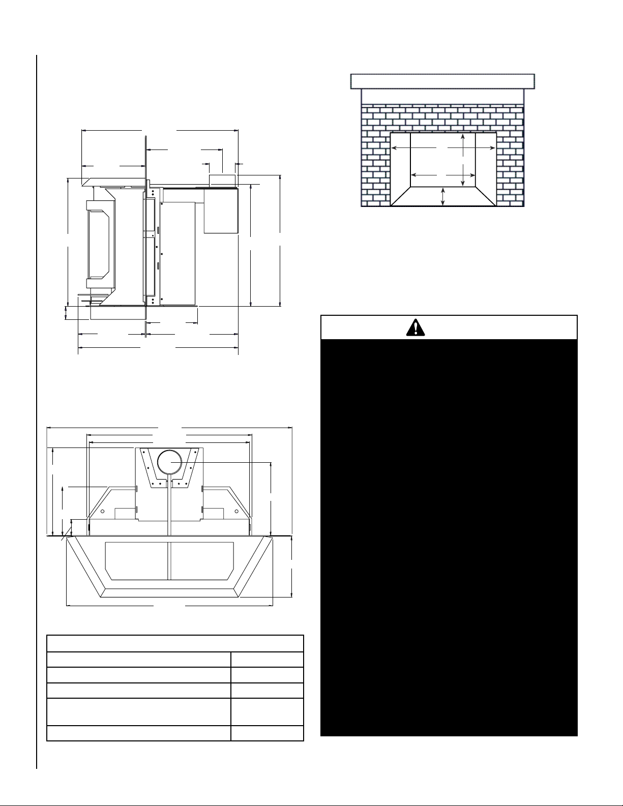
insert dimensions
See Figures 1, 2 and 3 showing insert dimensions and minimum fireplace firebox dimensions to aid you in determining
proper fit into existing fireplace.
* Equipped from the factory with a 2” filler. Contact your
dealer for additional information.
Figure 1
Figure 2
Width of insert behind Surround Panels 26-3/4”
Rear height 18-7/8”
Insert depth into fireplace 13-5/8”
Flue center line from back of surround with
standard draft hood
Flue collar diameter (OD) 3-15/16”
6
Insert Dimensions
11-3/8”
NOTE: DIAGRAMS & ILLUSTRATIONS ARE NOT TO SCALE.
minimum fireplaCe Cavity
Figure 3
minimum fireplaCe opening required
A = 29-3/4” Front Opening
B = 19” Height
C = 19” Rear Width
D = 15-1/4” Fireplace Depth
CAUTIONS
• The fireplace in which this gas insert is to be
installed must be thoroughly cleaned if it has
been used to burn wood or synthetic logs. Have
the chimney and all inside surfaces of the fireplace brushed and vacuumed so that no soot,
embers, or loose combustion deposits can be
drawn into the heat circulation blower and blown
into the living area.
• If any portion of the chimney system shows signs
of structural or mechanical weaknesses, such
as: cracks, leaky joints, corroded or warped
surfaces, the faulty portion must be repaired
or replaced prior to installing this appliance.
• The factory built firebox must accept the insert
without modification other than removing bolted
or screwed together pieces such as baffles /
smoke shelf / deflectors, ash lips, glass door,
screen or door tracks, log grates, refractory or
masonry lining and damper assemblies. Any
fireplace component, which is removed, must be
retained so they can be reinstalled to restore the
fireplace to its original operating condition. The
removal of any part must not alter the integrity
of the outer shell of the pre-engineered fireplace
cabinet in any way. Any parts removed must be
replaceable. If any components are removed
from (or altered) from the existing fireplace,
a Warning Label (see Page 4) must be affixed
inside the fireplace firebox, so that it shall be
visible upon removal of the fireplace insert. Note:
RTV high temperature silicone is an approved
adhesive to affix the label.
Page 7
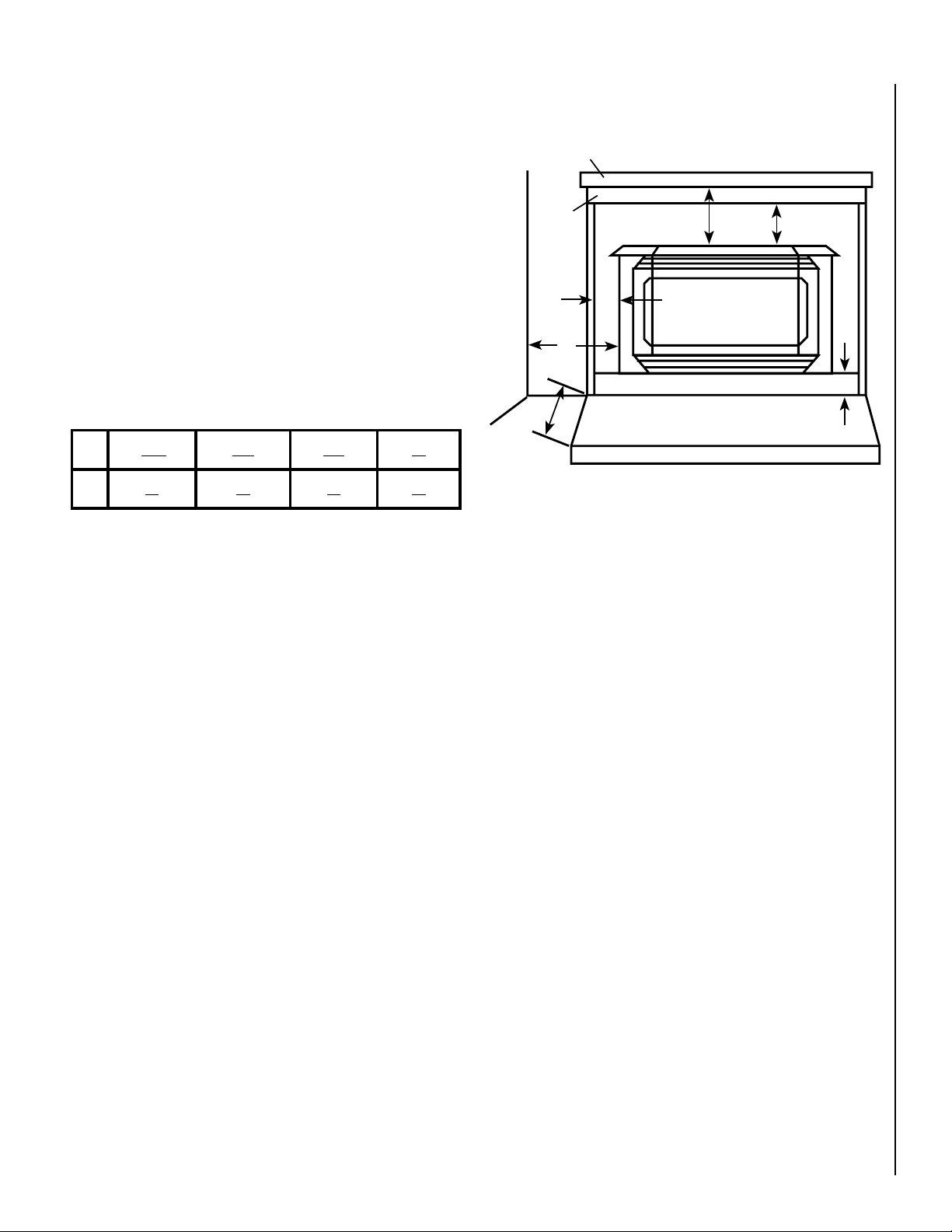
minimum ClearanCes to Combustibles
E**
F
H
D
C
Trim
Mantel
G
The letters below, C through H, correspond to Figure 4
showing minimum clearances required from the appliance
to combustibles and the minimum projection of the hearth
extension.
C = 6.5” to Side Facing (3/4” or less)
D = 11” to Side Wall
E = 24” to Mantel** (more than 3/4”)
F = 14.5” to Top Facing (maximum thickness 3/4”)
hearth proteCtion
G = Minimum Hearth Protection from Front of Insert*
H = Vertical Distance from Insert Bottom to Combustible
Material.
G
23” 20” 17” 0”
ClearanCes
Hearth / Floor Protection
H
(*Insert bottom is the metal lip below the lower gold trim bar).
0” 2” 4” 6”
Note: Hearth protection to be min. 3/8” (10mm) thick noncombustible or equivalent, with a k factor of .84.
insert leveling
The FireStar™ insert comes with four 3/8”X 3” leveling bolts
(two for use at the rear and two at the front of the insert).
The two at the rear can be used to raise the back of the insert
resting on the fireplace hearth. The two at the front can be
used to adjust the front of the insert on the hearth extension.
To install the bolts a 3/8” nut should be threaded onto the
bolt, followed by a 3/8” flat washer. The bolt should then
be installed from the under side of the insert into the captive
nut in the bottom of the insert. When the bolt is adjusted
to the proper height the nut previously threaded onto the
bolt can be snugged up to the insert bottom.
Figure 4
**The minimum distance from the top of the insert to a
combustible may be reduced to 16” with a mantel shield.
The shield should be made from 18-gage or thicker sheet
metal, 7” by 33”. The shield must be centered over the
insert and spaced one inch below the mantel. The shield
can be fastened to and spaced from the mantel using four
to six screws.
NOTE: DIAGRAMS & ILLUSTRATIONS ARE NOT TO SCALE.
7
Page 8
Installation
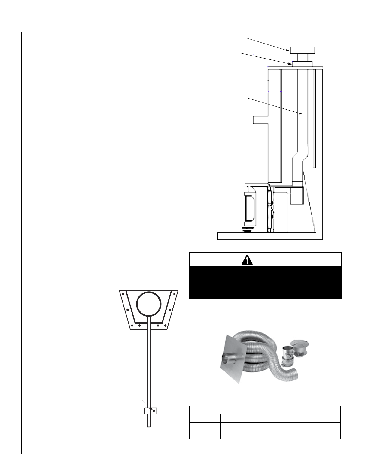
Draft Tube
Retaining
Screw
Chimney Cap
insert venting
Refer to Figure 6 which shows a typical installation of this appliance into an existing solid-fuel fireplace.
WARNING: This appliance is equipped with a safety control sys-
tem designed to protect against improper venting of combustion
products. Operation of this heater when not connected to a properly installed and maintained venting system or tampering with
the blocked vent shut-off system can result in carbon monoxide
(CO) poisoning and possible death.
Insert must be vented to the outside in accordance with the current
edition of the National Fuel Gas Code ANSI-Z223.1-latest edition,
also known as NFPA 54
chimney flue serving a separate solid fuel burning appliance.
This gas insert requires a 4” diameter B-vent or listed flex aluminum or stainless chimney liner extending the entire length
of the chimney to ensure proper operation. The vent should
terminate with a chimney cap or rain cap. Chimney should be
sealed around cap to prevent air and rain from entering chimney.
Adhere to vent manufacturer's instructions for installation and
vent termination.
. The insert must not be connected to a
Storm Collar
Chimney - Use With
B-vent Chimney Or
Single Wall Gas Vent
Flex Chimney Liner
Listed To UL 1777 Or
ULC S635.
8
A minimum flue height of 12 feet is recommended.
The insert must be installed so the draft hood is in the same
atmospheric pressure zone as the combustion air inlet to the
appliance.
flue Collar ConneCtion
This insert has a detachable flue
collar to ease installation. To detach
flue collar lift removable vent (trivet)
from top of insert, unscrew draft tube
retaining screw (see Figure 5) and
slide draft tube and flue collar to the
rear. Attach flue collar (with 3 sheet
metal screws or a B-vent connector)
to vent pipe previously installed in
chimney. As the insert is pushed into
fireplace guide draft tube and flue collar into guide brackets until draft tube
retaining screw can be reinstalled in
its original hole.
Figure 5
NOTE: DIAGRAMS & ILLUSTRATIONS ARE NOT TO SCALE.
Figure 6
WARNING
Do not substitute the heat-rated flex liner (UL1777 or ULC
S635) for the exhaust with any other type liner or a fire
may result causing property damage, personal injury or
loss of life.
The following vent liner kits are available from Lennox Hearth
Products (see Figure 7 and table below).
Figure 7
VENT KITS
Cat. # Model Description
H0906 VKBVI25 BVI, 4" Dia. x 25’ Length
H0907 VKBVI35 BVI, 4" Dia. x 35’ Length
Page 9

zero ClearanCe fireplaCe installation
Figure 1
Rear Log
Right Front Leg
Figure 2
Left Front Leg
Figure 1
Rear Log
log installation instruCtions
This insert may be installed in a masonry or factory built/zero
clearance (ZC) fireplace. When installing in a ZC fireplace,
the ZC grate must be removed and the ZC damper must be
removed or secured open. The ZC doors, screen, refractory
or masonry lining, baffles, and smoke shelf may be removed,
if necessary, to install the gas insert. However, do not cut
or alter the fireplace components. The removal of any parts
to facilitate installation must not alter the integrity of the
inner or outer shells of the fireplace cabinet. See Fireplace
Requirments on page 4.
glass door removal
See page 17 for Glass Door Removal Instructions.
briCk liner installation
HANDLE THE BRICK PANELS WITH CARE (SEE FIGURE 8)
AS THEY ARE FRAGILE. DO NOT FORCE THE PANELS INTO
THE FIREBOX AS THEY WILL BREAK IF FORCED.
1. Open and remove glass door, see “Front Door Remov
al”
2. The longest panel goes in the rear of the firebox. Tilt the
top of the panel forward, insert the bottom of the panel
in the brick panel retainer and push the panel to the upright position.
3. Install the side panels by sliding the top of the panel into
the top side brick retainer and then dropping the bottom
of the panel into the bottom retainer. The rounded edge
on the side brick panels goes toward the front.
CAUTION: If the logs are not properly installed, your insert
will not function properly.
Part list: Rear log, Right Front log, Left Front log, and
Top Twig
1. Remove the logs from the box and carefully unwrap them.
The logs are fragile, so handle them with care.
2. Place the rear log with the charred surface forward, on
the two rear locating pins (see Figure 9).
3. Place the left front log, with the charred surface forward,
(see Figure 10) on the two left front locating pins. Next
place the right front log, with the charred surface forward,
on the two right front locating pins.
Continued on Page 10...
Rear Log
Figure 9
-
Left Front
Log
Figure 8
3-Piece Brick Panel Set
Figure 10
NOTE: DIAGRAMS & ILLUSTRATIONS ARE NOT TO SCALE.
Right Front
Log
9
Page 10

Figure 3
Figure 4
Embers
Figure 3
log installation Continued (gC3)
surround installation
4. Position the top twig, with the charred end forward, on
the pin in the top of the rear log and the pin in the top of
the right front log (see Figure 11).
5. Place the volcanic stone one high in front of the front
burner tube (see Figure 12). Take care not to cover all the
burners ports. Any extra volcanic stone may be placed
at the ends of the front logs, off the burner. Place small
pinches of rockwool (embers) on top of the volcanic
stone.
Top Twig
Figure 11
Note: The pilot flame can be
viewed through the burned hole
in the right front log.
Install per the following instructions (refer to Figure 13).
The FireStar™ insert flanges are made of heavy 12 gage
steel for durability and, if desirable, for the ease of making
an inside fit in the fireplace. See “Packaging List” for sizes
available. The side flanges extend 2” below the bottom of
the insert and align with the 2” lower filler panel. In those
few instances when the elevation of the hearth necessitates,
2” can be cut from the bottom of the side flanges and the
insert placed directly on the hearth- not using the leveling
bolts or filler panel.
1. Remove the speed nuts from the parts bag and install
(with the flat surface forward) on the six holes in the
flange brackets (three on each side of the insert). A flat
bladed screwdriver may help in installing the nuts.
2. Install all flanges and trim with the insert positioned in the
fireplace but a few inches in front of its final location.
3. Open side doors and install the side flanges by lining up the
holes in the tabs on the side flanges in front of the holes on
the flange brackets. (Note that the larger tab on side flange
goes at the bottom and the front leveling bolts need to be
raised to at least two inches to accommodate the length of
the side flanges). Next insert two slotted 1/4” truss screws
for each side flange and secure loosely.
4. Fasten top flange with the remaining two truss screws.
Tighten all six truss screws after shifting flanges to
eliminate space between side and top flanges.
5. Install two spring clips approximately five inches from each
end of each of the three gold trim pieces. The spring clips
should be installed in the channel of the trim with the curved
end to the front toward the rounded surface of the trim.
6. Place the longest trim piece with the rounded surface
out along the edge of the top flange with the spring clips
slightly behind the flange. Pull the trim forward, com
pressing the spring clips, and slide the trim down onto
the flange.
7. Insert the elbowed retainer in the mitred end of the side
trim pieces and fasten with flat screwdriver. Insert the other
end of the retainer in the end of the already installed top
flange and slide side trim onto the edge of the side flange
compressing spring clips in the process. Repeat the same
steps for the other side trim. Fasten the elbowed retainer
securely in the top flange making a nice mitred corner.
-
10
Volcanic Stone
Figure 12
Figure 13
NOTE: DIAGRAMS & ILLUSTRATIONS ARE NOT TO SCALE.
Top Flange Mounting Holes
Side Flange Mounting Holes
Page 11

lower front 2” filler panel
1
/
2
"
(1.3 cm)
7
/
8
"
(2.3 cm)
3
/
4
"
(2.0 cm)
3
/
4
"
(2.0 cm)
150-200
3
/
4
"
(2.0 cm)
100-150
1
/
2
"
(1.3 cm)
7
/
8
"
(2.3 cm)
3
/
4
"
(2.0 cm)
1
/
2
"
(1.3 cm)
3
/
4
"
(2.0 cm)
1
/
2
"
(1.3 cm)
1
/
2
"
(1.3 cm)
40-100
1
/
2
"
(1.3 cm)
5
/
8
"
(1.6 cm)
1
/
2
"
(1.3 cm)
10-40
3
/
8
"
(1.0 cm)
1
/
2
"
(1.3 cm)
3
/
8
"
(1.0 cm)
1
/
2
"
(1.3 cm)
0-10
Natural Gas
Natural Gas L.P.L.P.
Pipe Length
(Feet from Supply
Regulator)
(Do Not Use Copper in Massachusetts
with Natural Gas)
Tubing, Type L Outside Diam-
eter (Copper)
Schedule 40 Pipe
Inside Diameter
(Black Pipe)
1
/
2
"
(1.3 cm)
.
Gass
upplylinesizinG
The proper gas line diameter must be selected to run from the
supply regulator to the stove. Refer to the following table for
proper gas pipe diameters.
NOTE: Some areas allow copper tubing - check with local approval
agencies and codes.
COPPER TUBING NOT ALLOWED IN MASSACHUSETTS IN
NATURAL GAS INSTALLATIONS, NEVER USE GALVANIZED OR
PLASTIC PIPES.
Inlet
Pressure
Tap
Inlet Elbow
Off/On/Pilot
Manifold
Pressure Tap
Flame Height
Adjustment
Outlet
Orifice
The FireStar™ insert comes with a 2” panel to fill the space between the insert bottom and the hearth extension. If the hearth
elevations necessitate, the insert may be installed directly on the
hearth without the leveling bolts or filler panel. To install the panel,
insert the four tabs on the top of the panel into the corresponding
slots in the insert bottom. Open the insert side doors, remove the
two socket head screws from the hardware bag and install them
(using a 5/32” hex wrench) through the insert bottom into the filler
panel. A tall adjustable filler panel is also available.
gas line installation
After leveling, position the insert in the fireplace, holding it about
six inches out from its final location.
Caution: Specific Hearth Requirements apply (see Clearances
and Specifications). The Firestar gas insert must be connected
to the gas line in accordance with local codes and / or the
National Fuel Gas Code, Z223.1-latest edition, also known as
NFPA 54. Included in the manual package is an 8" gas nipple.
Locate the threaded gas inlet on the lower left of the insert.
Thread the 8" gas nipple into the inlet with a teflon sealer or
equivalent. Attach the gas supply line to this hard pipe. The
hard pipe can receive a 3/8” inch female iron pipe coupling, or a
shut off valve. After connecting the gas line, all joints in the line
and connections at the valve should be checked for leaks.
gas pressure requirements
A MAJOR CAUSE OF OPERATING PROBLEMS WITH GAS
APPLIANCES IS IMPROPER GAS PRESSURE!
The most important item to check during the initial
installation and the first thing to check when operating
problems occur is gas pressure! This appliance will not
function properly unless the required gas pressure is
supplied. See Table 1 for gas pressure requirements.
Two pressure taps are provided on the insert's valve to check
gas pressures. The taps are located below the on/off/pilot knob
(see Figure 14). The left tap is the inlet (supply) pressure side.
To check inlet pressure (with the insert burning), insert a small
phillips screwdriver into the tap and turn a half turn counterclockwise. Cover the tap with the line from a manometer and
check the pressure. Close tap gently but securely after completing
the check. The manifold (outlet) tap is to the right of the inlet tap.
To check manifold pressure (with the insert burning at the high
burn setting) insert a small
phillips screwdriver into
the tap and turn a half turn
counter-clockwise. Cover
the tap with the line from
the manometer and check
the pressure. Again close
the tap gently but securely
after completing the check.
Check the taps for gas leaks
with a gas leak test solution
(retighten if necessary).
If the pressure is not sufficient, make sure the gas supply line
is large enough, the supply regulator is properly adjusted, and
the total gas load for the residence does not exceed the amount
supplied.
The appliance and its individual shut off valve must be
disconnected from the gas supply piping system during any
pressure testing of that system at test pressures in excess of
1/2 psig.
The appliance must be isolated from the gas supply piping
system by closing its individual manual shut-off valve during
any pressure testing of the gas supply piping system at test
pressures equal to or less than 1/2 psig. Check with your gas
supplier or plumber.
Fuel
Type
Natural
Gas
LP Gas 11" WC 10.5" WC 13" WC 10.0" WC 5.4” WC
Table 1
gas supply line sizing
Figure 14
NOTE: DIAGRAMS & ILLUSTRATIONS ARE NOT TO SCALE.
The proper gas line diameter must be selected to run from the
supply regulator to the insert. Refer to the Table 2 for proper gas
pipe diameters.
NOTE: Some areas allow copper tubing - check with local approval
agencies and codes.
COPPER TUBING NOT ALLOWED IN MASSACHUSETTS IN
NATURAL GAS INSTALLATIONS, NEVER USE GALVANIZED OR
PLASTIC PIPES.
Table 2
Inlet Pressure Manifold Pressure
Desired Minimum Maximum On Hi
Fire
On Lo
Fire
7" WC 5" WC 10.5" WC 3.5" WC 1.7" WC
11
Page 12

propane (lp) and natural gas supplies
Your Firestar™ gas insert is equipped from the factory for
use with natural gas only as specified on the Safety / Listing
label attached to the appliance. This appliance can only be
operated using propane gas (LP) if a certified fuel conver
sion kit provided by Lennox Hearth Products is installed by
a qualified service technician.
Also check the orifice size on the label attached to your control
panel. It must be the correct size for the fuel and altitude.
Do not run propane tank dry. Running the tank dry may
cause a hazardous condition due to pressure drop in
empty tank.
Solid fuel is NOT to be used with this unit.
air shutter adjustment
The main burner has an adjustable air shutter located at
the end of the burner as it inserts over the orifice. It is
located behind the right side door and beneath the control
valve. The shutter adjustment has been set at the factory
to ensure proper, safe combustion and flame pattern. Only
a qualified gas technician should adjust the air shutter as
an incorrect adjustment could cause a hazardous condition.
Closing the air shutter will cause the flames to take on a
yellow color. Closing it too far will cause improper burning
and the flames will turn orange and sooty. Opening the air
shutter will cause the flames to burn cleaner; becoming
transparent and bluish.
Caution: The air shutter should never be closed to such
an extent to create sooting on the viewing glass, logs or
heat exchanger. If soot begins to form after burning, the
air shutter should be opened gradually until the sooting
condition stops. Open the shutter a small amount at a time
until the sooting ceases. See “Flame Color and Behavior”
and “Maintenance”, proper pilot flame.
1. Remove glass door (see Glass Door Removal on page
17). Carefully remove the log set and set aside.
2. Using a 5/32” allen wrench, remove the allen-head screw
on the left side of the air control panel as shown in Figure
15a, then lift out air control panel as shown in Figure
15b.
3. Using a 5/32” allen wrench, remove the screw which
secures burner tube assembly as shown in Figure 15c.
Then lift out burner tube assembly as shown in Figure
15d.
4. Using a phillips screwdriver, loosen the air shutter setscrew
just enough so air shutter can be rotated by hand (read
note below). See Figures 15e and 15f.
5. Reinstall components by reversing steps 1 - 4.
6. Locate the air shutter, behind the right side access door
(below valve), then adjust the air shutter gap until the
proper flame characteristics are achieved.
Note: The setscrew for the air shutter is secured tightly
from the factory so that it does not rotate from the factory
setting during shipping. Once you loosen the setscrew just
enough so that it can be rotated by hand, then reinstall the
burner tube, you will be able to access and adjust the air
shutter from behind the right side panel (below valve).
12
-
Figure 15a
Lift Out Air Control Panel
Figure 15b
Figure 15c
Lift Out Burner Tube Assembly
Figure 15d
Setscrew
Air Shutter
Figure 15e Figure 15e
Firebox
Air Control Panel
Remove Allen-Head Screw
Remove Allen-Head Screw
Burner Tube Assembly
Air Shutter
Page 13

Operating Instructions
pre-lighting CheCklist
Be sure to check these items before the initial lighting of
the insert:
- All packaging materials are removed from the firebox;
brick panels and logs are installed.
- The insert gas label must correspond to the gas supply
available, that is “natural gas” for natural gas; "LP gas"
for LP gas.
- Be sure the gas pressure has been carefully checked (see
Gas Pressure Requirements).
- Fingerprints or other marks are cleaned (while the insert
is cool) from any gold or nickel surfaces with denatured
alcohol and a soft cloth. Marks left on these surfaces
may become etched into the finish if not removed prior
to burning the unit.
- Check all gas fittings for leaks.
- Remove all combustible materials from the area in front
of the insert and ensure the vented areas of the insert face
are unobstructed.
- Check to ensure all clearances to combustibles are metsee page 7.
- Make sure the glass door is in place and properly sealed
before burning the appliance
- Ventilate the house to clear initial paint curing odors, see
page 15.
Lighting Instructions
The following is a copy of the operating and lighting instructions found with each insert:
FOR YOUR SAFETY READ BEFORE OPERATING
WARNING: IF YOU DO NOT FOLLOW THESE INSTRUCTIONS
EXACTLY, A FIRE OR EXPLOSION MAY RESULT CAUSING
PROPERTY DAMAGE, INJURY, OR LOSS OF LIFE.
CAUTION: HOT WHILE IN OPERATION. DO NOT TOUCH. KEEP
CHILDREN, FURNITURE, GASOLINE, AND OTHER LIQUIDS
WITH FLAMMABLE VAPORS AWAY. NEVER OPERATE UNIT
WITH GLASS OFF OR ATTEMPT TO REMOVE THE GLASS
WHILE HOT.
A. This appliance is equipped with a piezo ignition device
to light the pilot. When lighting the pilot, follow these
instructions exactly.
B. BEFORE LIGHTING, smell around the appliance area for
gas. Be sure to smell next to the floor, because some gas
is heavier than air and will settle on the floor.
WHAT TO DO IF YOU SMELL GAS:
DO NOT try to light the appliance.
DO NOT touch any electric switch,
DO NOT use any phone in the building. Immediately call
your gas supplier from a neighbor's phone. Follow the gas
supplier's instructions. If you cannot reach your gas supplier,
call the fire department.
C. Use only your hand to push in or turn the gas control
knob. Never use any tool. If the knob will not push in or
turn by hand, don't try to repair it, call a qualified service
technician. Force or attempted repair may result in a fire
or explosion.
D.
DO NOT use this appliance if any part has been under water.
Immediately call a qualified service technician to inspect
the appliance and to replace any part of the control system
and any gas control which has been under water.
OPERATING INSTRUCTIONS
(Refer to controls shown in Figure 16)
CAUTION: Your Lennox™ gas INSERT MUST ALWAYS BE
OPERATED WITH GLASS IN PLACE.
STOP!! Read the safety information above before proceeding.
1. Open the lower door. Make sure gas supply shut-off cocks
are open and ON/OFF rocker switch is "OFF." If equipped
with a thermostat, set it to the lowest setting.
2. Turn off all electrical power to the appliance.
3. Push in gas cock dial slightly and turn clockwise to
"OFF."
NOTE: Dial cannot be turned from "PILOT" to "OFF" unless
dial is pushed in slightly. Do not force.
4. Wait five minutes to clear out any gas. Then smell for gas,
including near the floor. If you smell gas, STOP! Follow
"B" above. If you don't smell gas continue.
5. Locate the pilot by looking over the top of the left front
log. A blue flame will be seen when the pilot is lit.
6. Turn the gas control knob counter-clockwise to
the "PILOT" position.
7. Push the knob all the way in and hold in that position.
Immediately light the pilot by pressing the igniter button
several times until pilot is lit. Continue to hold the knob in
for about 30 seconds after the pilot is lit. Release knob and
it will pop back out. Pilot should remain lit. If it goes out,
repeat steps 4-8 holding knob in an additional 15 seconds
after pilot is lit. If knob does not pop out when released,
stop and immediately call your service technician or gas
supplier. If the pilot will not stay lit after several tries,
turn the gas control knob to "OFF" and call your service
technician or your gas supplier.
8. After pilot is lit, turn gas control knob counter-clockwise
to "ON." Knob can only be turned to "ON" if the
knob has popped out.
9. To turn burner on, turn "ON/OFF" rocker switch to "ON"
or set the thermostat to the desired temperature above
room temperature.
10. Adjust the flame height (and heat output) by turning the
flame height knob clockwise for full flame and
counter-clockwise for reduced flame.
11.Turn on the electric power to the appliance and set the
blower to the desired air flow after it turns on when the
appliance reaches operating temperature.
13
Page 14

TO TURN OFF GAS TO APPLIANCE
OFF
ON
Off/On/Pilot
Flame Height
Adjustment
LO
HI
flame Color & behavior
(Refer to controls shown in Figure 16)
1. Turn off the "ON/OFF" rocker switch and/or thermostat (if
installed) to its lowest setting.
2. Turn off electric power to the appliance if service is to be
performed.
3. Push in gas control knob slightly and turn clockwise
to "OFF." Do not force.
This appliance needs fresh air for safe operation and
must be installed so there are provisions for adequate
combustion and ventilation air.
WARNING: Improper installation, adjustment, alteration,
service, or maintenance can cause injury or property damage. For assistance or additional information, consult a
qualified installer, service agency, or your gas supplier.
Operation of this appliance when not connected to a properly installed and maintained venting system can result in
carbon monoxide (CO) poisoning and possible death.
SHUTDOWN PROCEDURE
To turn off the burner, turn the rocker switch to "OFF" or
adjust the thermostat (if installed) to a setting below room
temperature. The pilot will remain lit for future burner igni
tion. For complete shutdown, see "TO TURN OFF GAS TO
APPLIANCE" above.
Your Firestar™ gas insert is designed for maximum heating
efficiency. Therefore, upon lighting of the main burner the
flames will be semi-transparent or “bluish.” After 10-20
minutes of operation the logs will heat up and the flames
will become a yellow/orange color.
Adjusting the insert to cause the flames to turn orange
sooner may result in poor combustion, sooting, and a
hazardous situation. See Figure 17 showing proper flame
appearance.
Burner Flame Appearance
Soot at
Flame Tip
Dark Orange
Flame
No Blue Flame
Center
IMPROPERLY
BURNING FLAME
Soot above
Flame Tip
Ports on Pan
Burner Assembly
BURNING FLAME
No Soot at
Flame Tip
Semi-Transparent
Yellow Flame
Blue Flame
Center
PROPERLY
Figure 17
-
replaCing burner orifiCes
To change orifices, first remove the cassette (see Fuel Conversion and Cassette Installation on page 19). Then unscrew
orifice using an 3/4” open end wrench, discard the old orifice
and reinstall the new orifice.
14
Robertshaw
Gas Valve
ON/OFF Switch
Figure 16
Piezo Igniter
Gas Control
Knob Off/On/Pilot
Flame Height
Control Knob
(Hi/Lo)
Millivolt Pilot
Gas Pilot Hood
3/8” to
1/2”
Thermopile
Igniter
NOTE: DIAGRAMS & ILLUSTRATIONS ARE NOT TO SCALE.
REDUCING THE ORIFICE SIZE FOR HIGHER ALTITUDES
MAINTAINS THE PROPER BTU INPUT TO AIR RATIO. TOO
LARGE AN ORIFICE WILL RESULT IN HIGHER BTU INPUTS
THAN THE DESIGN ALLOWS, MAY RESULT IN AN UNSAFE
CONDITION AND MAY VOID YOUR WARRANTY.
For altitudes above 2,000 ft. (610M) the appliance should be
derated by four (4%) percent every 1,000 ft. (305M).
To operate safely, your Firestar gas insert must have the
proper burner orifice size determined by the altitude at
which it will be operated and other variables such as pres
sure and valve tolerances. If you have reason to believe
your insert’s orifice size may be incorrect for your altitude,
have it checked and remedied (if necessary) by a qualified
service technician.
-
Page 15

paint Curing
“on-off” switCh and thermostat
This insert has been painted with Stovebright high temperature metallic stove paint. It leaves the factory dry to
the touch, but finishes curing as the insert is used. Fire the
insert four successive times for ten minutes each time with
a five minute cool down between each firing. Ventilate the
house during these first firings as the paint gives off car
bon dioxide and unpleasant odors. It is recommended that
persons sensitive to an imbalance in the indoor air quality
avoid the insert during the curing process.
quiet operation
GAS NOISE: The sound of gas flowing through the insert
may be detectable while the unit is in operation. This is a
normal operating sound, however if it is objectionable, it
can be reduced by turning down the flame. Turning down
the flame will reduce heat output.
BLOWER NOISE: As the insert heats up, the blower will come
on to move hot air through the heat exchanger and into the
room. Adjust the fan speed with the fan control knob to the
sound level and air flow desired.
blower
Your Firestar™ gas insert comes equipped with a 150 CFM
blower with a variable speed control and an automatic
temperature activated On / Off snap switch.
Operation:
Your gas insert comes equipped with an “ON-OFF” rocker
switch used to turn the burner on and off while the pilot is
on. The switch is located behind the right side door to the
right of the control valve. This switch can be relocated to
the hole provided in the top surround panel by pulling the
two connectors off of the spades on the back of the switch.
Then unscrew the plastic nut on the back side of the switch
and pull the switch forward through the hole. Cut the wire
tie holding the switch wire and feed the wire behind the side
flange up to the switch hole in the top flange. Care must be
taken to ensure the wire is kept away from the heat of the
firebox. Reinsert the switch in the hole in the flange, tighten
the retaining nut, and push the wire connectors back on the
spades. The spades may need to be carefully bent downward
to provide clearance between the switch and the fireplace
facing material.
A millivolt wall thermostat or remote thermostat can be used
to supplement the rocker switch. The thermostat and rocker
switch will turn the burner on and off independently of each
other. Be sure to set the rocker switch to the off position
when using the thermostat and set the thermostat to the
lowest temperature when you wish to use the rocker switch
only, otherwise one may override the other.
Follow the instructions included with the thermostat for
wiring. Solder all connections, as good wire connections
are critical in millivolt system. Check with your insert dealer
for the proper length and size of the thermostat wire. Both
factors effect the function of the thermostat.
1. Plug the blower power cord into a grounded (three
prong) outlet. This appliance is equipped with a three
prong (grounding) plug for your protection against
shock hazard and should be plugged directly into a
properly grounded three - prong receptacle. Do not cut
or remove the grounding prong from this plug.
2. After the insert warms up, the fan will come on if the
speed control (located at the bottom of the left side
door) is left in the on position. The fan will not operate
until the insert is warm.
3. Once the fan comes on, turn the knob to the desired
speed. No further adjustment is necessary, the fan will
come on automatically whenever the insert is warm.
4. If you do not wish to have the fan on, turn the knob until
it clicks into the OFF position.
pilot adjustment
All pilots are burned and checked at the factory prior to
shipment. (NOTE: If upon initial insert installation the pilot
flame flickers or will not remain lit, most likely the pilot is
fine but there is air in the gas line or the gas pressure is too
low). Pilot adjustment is not normally required, but should
it be necessary, it should be done only by a qualified service
technician. The pilot adjustment screw is located to the
left of the ON/OFF/PILOT control knob. With a flat bladed
screwdriver, remove the pilot adjusting cover to access the
pilot adjusting screw. Adjust pilot screw to the properly sized
flame as shown in Figure 18. The flames should completely
surround the thermopile and extend across the main burner
ports. Be careful not to back the adjusting screw out of its
threads. Replace the cover and check for gas leaks.
Millivolt Pilot
Gas Pilot Hood
3/8” to
1/2”
Thermopile
Figure 18
NOTE: DIAGRAMS & ILLUSTRATIONS ARE NOT TO SCALE.
Igniter
15
Page 16

Do not splice any millivolt wires. Refer to Table 3 to determine
Thermopile
Pilot Hood
Pilot Tube
Spark Electrode
Terminal Snap Switch
Wire (Black SS1)
Spark Electrode Wire
(Black) connect to
Piezo Igniter
Burner Orifice
Thermopile Wire (Brown)
Connect to Terminals 1 & 2
On Gas Valve
On/Off Switch Wire
(Black) 001 Connect
Terminal 1 Gas Valve
Inlet Pressure
Tap
Gas Valve
Valve Snap Switch
Wire (Black) SS2
Inlet
Elbow
Piezo Igniter
On/Off Switch Wire (Black) 002 - Connect Terminal 3 Gas Valve
Off/On/Pilot
Manifold
Pressure Tap
Flame Adjustment
On/Off
Switch
Thermostat
Wire
(White) TH2
Thermostat
Wire
(Red) TH1
OPTIONAL
Thermostat
Vent Safety Snap
Switch
50
60
70
80
90
50
60
70
80
90
Terminal 2
TP
Terminal 3
TH
TH
TP
TH
Terminal 1
TH/TP
the proper gage of wire for the thermostat or wall switch
connections. This table refers to the total length of the wire
(out to the switch and back). The thermostat must be a
millivolt type. A 24-volt furnace thermostat will not work.
Never hook up household current, 120 Volts, to the millivolt
system. It is not recommended to hook up any more than
two switches to the insert (for example a rocker switch and a
wall thermostat). Additional switches may affect the system
resistance and increase the chance of the burner not ignit
ing. Follow the instructions included with the thermostat or
remote control for wiring.
The thermostat, remote control, and rocker switch will turn
the burner on and off independently. Be sure to set the rocker
switch to the “OFF” position when using the thermostat or
remote control and set the thermostat or remote control to
the lowest temperature when you wish to use the rocker
switch only, otherwise one may override the other. If a re
mote thermostat is to be used with the insert, do not place
the receiver under the firebox.
Thermostat Wire
Wire Size Maximum Length
12 Gage
100 Feet
14 Gage 64 Feet
16 Gage 40 Feet
18 Gage 25 Feet
20 Gage
16 Feet
Table 3
millivolt Control system
This insert operates on a millivolt control system. As such, no
addition power supply is needed for the insert to operate. The
pilot assembly contains a Thermopile, that when heated by the
pilot flame, generates electricity (millivolts, mV=1/1000 of a volt)
that travels to terminal #1. From this terminal it travels through
a black wire to the Vent Safety Snap Switch. If this switch overheats through a flue blockage or vent pipe disconnection it will
open, stop the flow of mV and shut the insert off. This switch will
-
automatically reset (close), when it is cooled down to normal
operating temperature. During normal operation, it is closed
allowing the mV to flow back to the valve, which opens so gas
can flow through.
To check for proper operation, use a multimeter and perform the
system checks shown in Table 4 (and refer to Figure 19).
-
Check
Test
A Complete
B Thermopile
C System
Table 4
Millivolt and System Checks
To
Test
System
Output
Resistance
Connect
Meter
Thermostat
Connects
Leads to
Terminals
2 & 3 Closed 100 MV
1 & 2
Open Greater
1 & 3 Closed 80 Ohms
Meter
Reading
Should Be
or More
Than
325 MV
16
millivolt wiring diagram
Figure 19
NOTE: DIAGRAMS & ILLUSTRATIONS ARE NOT TO SCALE.
Valve Terminals
Page 17

Maintenance & Servicing
maintenanCe CheCklist
Should Only Be Performed by a Qualified Service Technician.
Caution: Label all wires prior to disconnection when
servicing controls. Wiring errors can cause improper
and dangerous operation. Verify proper operation after
servicing.
1. Annual inspection should be made and the following
checks performed:
a) With unit cool, remove glass and inspect burner for dirt,
soot, and lint accumulations and remove if necessary.
If excessive soot accumulation is present on burner,
have a qualified serviceman adjust burner for proper
combustion.
b) Clean any deposits from inside glass with gas fireplace
glass cleaner. NEVER attempt to remove or clean glass
when the unit is hot.
c) Check that chimney and its outlet are open and free from
soot, blockage, or debris.
d) Inspect the pilot system for proper flame. See instruc-
tions on page 15.
e) Check the Millivolt system as per Table 4 on page 16.
f) The appliance area must be kept clear and free of com-
bustible materials, gasoline, and other flammable vapors
and liquids.
g) Check glass gaskets once a year. Gaskets must be tight.
Replace if necessary.
glass door removal
(refer to Figures 20a and 20b)
Caution: Do not slam or strike glass door or damage
may occur.
Do not remove the glass door while the insert is hot.
both latches on the right and left side of the door (they
are centered on the sides of the front door - see Figure
20a). With the latches released, rotate the catch part of
each latch outward away from the front door. The door
will pivot toward you from the top (hinging from the bottom
as shown in Figure 20b). On the bottom of the door there
are tabs that slide into slots on the firebox. Disengage the
tabs on the door from the slots on the firebox by lifting up
on the door until it stops and slide the door all the way to
the left. You can then remove the door straight out from
the slots. To reinstall door reverse the steps above.
Side Door Latches
Open
2. The viewing glass should be cleaned periodically (see
Glass Maintenance).
glass maintenanCe
Cleaning: When cool, the glass may be cleaned with a clean,
soft cloth and Windex. For cleaning white condensation from
the interior glass, use KEL KEM gas fireplace glass cleaner
available from your insert dealer. Use of caustic or abrasive
cleaners may damage the glass. DO NOT operate the insert
with broken glass. DO NOT clean door or glass when hot. DO
NOT abuse the glass door by striking or slamming it shut.
DO NOT use substitute materials if replacing the glass. DO
NOT spray commercial glass cleaner with ammonia on the
door and glass gasket as it may dissolve the gasket glue.
Replacement: The glass in the insert door cannot be replaced
separately. Should the glass be damaged, the entire glass,
gasket, and metal frame assembly must be replaced as a
unit. This replacement glass assembly is available from your
Lennox Hearth Products dealer. The glass is neo-ceramic
and alternative types must not be used.
WARNING: Do not operate appliance with the glass panel
removed, cracked, or broken. Do not remove glass door
while the insert is hot. Replacement of the glass door
should be done by a qualified service technician.
Open the top door latches by pulling them forward and up.
Figure 20a
Lower Front Door Tabs
Door
Lift the glass door up and off the lower spring latch
Figure 20b
NOTE: DIAGRAMS & ILLUSTRATIONS ARE NOT TO SCALE.
17
Page 18

To remove the front door open the side doors, release the
Snap Switch Connection
Wire (Black)
Pan Snap Switch
Snap Switch
Connection
Wire (White)
Speed Control Connection
Speed control Connection Wire (Black)
Blower
Main Power Cord (Black)
Main Power Cord Wire (White)
Main Power Cord Wire (Black)
Ground Wire (Green)
Speed Control ConnectionWire (White)
Speed Control Connection Wire (Black)
Speed Control
Connection Wire
(White)
Speed Control
Wire (Red)
Fan Speed Control
Speed Control
Wire (Red)
front door latches on either side and rotate the top of the
glass door forward and down until it stops. Once it is all
the way open, lift it slightly, move it to the left and pull it
away from the insert. Place door on a nonabrasive surface
being careful not to damage door or glass. When cooled the
exterior glass may be cleaned with a clean, soft cloth and
windex. For cleaning white condensation from the interior
glass use KEL KEM gas fireplace glass cleaner available
from your insert dealer. Use of caustic or abrasive cleaners
may damage glass.
NOTE: BE CAREFUL NOT TO SPRAY COMMERCIAL GLASS
CLEANER WITH AMMONIA ON GASKET AREA OF DOOR.
AMMONIA WILL DISSOLVE GASKET GLUE.
NOTE: GOLD PLATED SURFACE MUST BE CLEANED WITH
GLASS CLEANER AND SOFT RAG BEFORE FIRING THE
FIRST TIME OR FINGER PRINTS AND STAINS WILL REMAIN
PERMANENTLY. NEVER USE BRASS POLISH TO CLEAN
GOLD, THIS WILL REMOVE GOLD PLATING!
Front door glass replacement should be completed only by
a qualified technician.
glass door Cleaning and repair
Cleaning: Do not remove or clean the glass door when hot.
A gas door glass cleaner (available from your Lennox Hearth
Products dealer) or windex should be used with a soft cloth
to clean the glass. Do not use an abrasive cleaner.
Repair: If the glass is broken in the glass door, the entire
door (metal frame, gasket, and glass) should be replaced
as a unit. This replacement unit is available from your Len
nox Hearth Products dealer. Do not use substitute parts or
materials.
blower removal
Unplug the power supply cord from the electrical outlet prior
to removing the blower. The fan can be accessed through the
back wall of the firebox.
Caution: Label all wires prior to
disconnection when servicing controls. Wiring errors can
cause improper and dangerous operation. Verify proper
operation after servicing. See the fan-wiring diagram below
for reference. Remove the glass door, log set, and brick pan
els. All of these items are fragile so handle them with care.
Remove the two allen-head screws at the left and right front
of the air control panel and lift the panel out. Next, remove
the nine allen-head screws around the outside of the panel
fastened to the back wall of the firebox. Rotate the top of
this panel toward the front, remove the two wires connected
to the fan, and then lift the panel with the fan attached out
of the firebox. To reinstall the fan, repeat these steps in the
reverse order.
eleCtriCal requirements
This gas insert operates without an outside power source,
however the fan/blower requires a 120 Volt electrical service
outlet. The blower must be electrically grounded in accor
dance with local codes. In the absence of local grounding
codes, the National Electrical Code ANSI/ NFPA 70 - latest
edition. The blower is equipped with a three pronged (ground
ing) plug for your protection against electrical shock hazard
and should only be plugged into a properly grounded three
prong receptacle.
ING PRONG FROM THE PLUG FOR ANY REASON!
• See Millivolt Control Schematic (Figure 19) for information
on thermostat and On/ Off switch.
• See Blower Wiring Diagram (Figure 21) for information on
-
the wiring and electrical requirements for the blower.
DO NOT CUT OR REMOVE THE GROUND-
-
-
-
Caution: Do not operate this insert with broken glass.
blower wiring diagram
Figure 21
18
NOTE: DIAGRAMS & ILLUSTRATIONS ARE NOT TO SCALE.
Page 19

fuel Conversion & Cassette installation
Converting your FireStar™ gas insert between natural gas and
LP can be accomplished by either changing the Quick Change
Cassette (valve and pilot assembly) or installing a conversion kit
(regulator, burner orifice and pilot orifice). Only a qualified service
technician should perform the conversion, as it requires disconnecting the gas supply line and other procedures that should only
be performed by a qualified technician.
Cassette Removal
1. Be sure the gas supply is off and fan power cord is disconnected before beginning the conversion. Disconnect the gas
supply from the insert being careful not to apply pressure to
the valve in the process.
2. Remove the log set and brick panels, (see “Brick Panel & Log
Installation)
3. Remove the burner by lifting the left end and pulling the burner
gently through the block plate and past the pilot assembly.
4. Disconnect at the valve the two wire connectors from vent
safety snap switch (the uppermost black wire on terminal 1
and the black wire with the round connector located at the top
of the valve and behind the gas inlet elbow). Then disconnect
the thermostat (red and white wires) and rocker switch (black
wires) at terminals #1 & 3.
5. Remove the socket head screw attaching the cassette/body
block plate and block plate located in the bottom right end
of the firebox.
6. Remove the socket head screw fastening the pilot end of the
cassette to the burner holder.
7. Remove the three socket head screws holding the cassette
(valve/pilot assembly) to the body of the insert.
8. The cassette can now be removed by rotating the valve for
ward and out to the right.
9. Install new, converted or serviced cassette in the reverse order
of removal. All parts and wires must be correctly reinstalled
to ensure safe and proper operation of the unit.
Conversion kit
Please see instructions provided with conversion kit.
-
NOTE: DIAGRAMS & ILLUSTRATIONS ARE NOT TO SCALE.
19
Page 20

Troubleshooting
NOTE: When troubleshooting the gas control system, be sure the external gas shut off valve, located at the gas supply inlet is in the “ON” position.
IMPORTANT: Call your gas supplier or plumber for additional help with any gas control problem. Valve system
troubleshooting should only be accomplished by a qualified service technician.
SYMPTOM PROBABLE CAUSE CORRECTIVE ACTION
Thin black coating (soot)
forms on the viewing
glass, logs, or firebox
Humming or whistling
coming from insert.
A change in flame appear
ance or burner operation.
Spark igniter will not light
pilot after repeated tries.
Pilot will not stay lit after
carefully following lighting
instructions.
Pilot burning, but no
flame on main burner with
valve knob “ON”, rocker
switch and thermostat
“ON”.
1) Improper log or
ember placement
2) Improper air shutter
setting
3) Not enough combustion air
4) Incorrect gas pressure
1) Normal operating
noise
2) Obstructed orifice
opening
3) Defective regulator
-
1) A change in gas
pressure
2) Improper ember
placement
1) No gas supplied to
unit or air in line
2) Defective igniter (no
spark at electrode)
3) Defective or mis
aligned electrode at pilot
(spark at electrode)
1) Vent Safety Snap
Switch shut down.
2) Improper Flame
impingement
3) Low gas inlet pressure
4) Defective thermopile
5) Bad connection
6)Defective automatic
valve operator
1) Pilot has gone out
2) Rocker switch,
thermostat, or wires
defective
3) Thermopile may not
be generating sufficient
millivolts
4) Plugged burner
orifice.
1) See Log Set Installation on Pages 9 & 10. If there is soot in one specific location, the
rockwool below this location needs to be adjusted. This can be done by pulling embers
forward slightly. If the flames have soot tails, the shutter will need to be opened.
2) If sooting continues open air shutter (see Air Shutter Adjustment on Page 12)
3) Check for debris obstructing air flow in valve compartment under insert or in front of
lower venting.
4) Have gas supplier check for correct gas pressure (7" W.C. natural gas: 11" W.C. propane gas)
1) See Quiet Operation on Page 15. The noise may be reduced by slightly turning down
the flame. Turning the flame down will reduce the heat output of the insert.
2) If noise is excessive or is “whistling” have your gas supplier check the regulator and
orifices and replace if necessary.
3) If noise is excessive or is “whistling” have your gas supplier check the regulator and
orifices and replace if necessary.
1) Have your gas supplier check for correct gas pressure (7" W.C. / po. C.E. [1.74 kPa]
natural gas; 11" W.C. / po. C.E. [2.74 kPa] LP gas). NOTE: NEVER BLOCK OR OBSTRUCT
AIR INTAKE OR OUTLET VENTS.
2) See Log Set Installation Instructions.
1) Check gas supply. To purge, hold in gas cock on valve for 1-2 minutes and try again.
2) Check for spark at electrode and pilot, if no spark and electrode wire is properly con
nected, replace igniter and igniter wire.
3) Using a match, light pilot. If pilot lights, turn off pilot and trigger the igniter again.
-
If pilot lights, an intermittent gas/air supply may be the problem, if longer purge will
not light - check gap between electrode and pilot - should be 1/8 inch (3 mm) to have a
strong spark. If OK, replace pilot.
1) Snap switch activated, have venting system inspected for blockage, down draft or
bad snap switch.
2) Check pilot flame adjustment (see "Maintenance" section).
3) Check inlet pressure and adjust pilot if necessary.
4) Be sure wire connections from thermopile are tight at gas valve terminals and at vent
safety snap switch.
5a) Either rocker switch or thermostat wires may be grounded. Remove wires from valve
terminals. If pilot stays lit, trace switch wiring for a ground. May be grounded to insert or
gas supply.
5b) Check open circuit millivolt output of thermopile. Reading should be greater than
325mV. Also check thermopile wire for kinks that can cause loss of mV. Replace faulty
thermopile if wire is okay and reading is less than 325mV.
6)Turn valve knob to “ON” and thermostat (if installed) to 90º. Millivolt meter should read
greater than 100 mV. If reading is OK and burner does not turn on, replace gas valve
(qualified service technician only).
1) See Lighting Instructions.
2) Disconnect rocker switch and thermostat wires at terminals 1 and 3 on valve. Jumper
across from 1 to 3 with pilot lit. If burner comes on either rocker switch, thermostat, or
wiring is not functioning. If not, jumper wires across switch wires at gas valve. If burner
comes on, wires are faulty or connections are bad.
3) Check thermopile with millivolt meter (see Maintenance and Servicing), recheck
symptom #2.
4) Check burner for stoppage and remove.
-
20
Page 21

REPLACEMENT PARTS LIST
PART # DESCRIPTION
H5952 #33 NG Main Burner Orifice
H5953 #35 NG High Elevation Main Burner Orifice
H5951 #50 LP High Elevation Main Burner Orifice
H5843 2” Bottom Trim Piece
H5950 #49 LP Main Burner Orifice
H5860 4 Piece Log Set
H5844 Air Control Burner Pan
H5842 Baffle Plate
H5519 Baffle Plate Holder Brackets
75145 Black Door w/Glass
H5874 Blower Power Cord
H5877 Blower Speed Control
H5996 Blower Speed Control And Housing (Includes 2 Rivets)
H5997 Blower w/Mounting Bracket
H5866 Brick Panel Set
H5934 Burner Tube
H5740 Cassette Assembly NG (For LP Installations, Also Order LP Conversion Kit)
H5863 Volcanic Stone
H5985 Decorative Gold Bar On Lower Stove Body
H5986 Decorative Nickel Bar On Lower Stove Body
H5905 Door Rope (Per Foot) Order 8 Ft. for each door
75146 Gold Door w/Glass
H5875 Heat Sensed Blower Snap Switch
H3106 Left-hand Side Door (Mounting Brackets & Blower Speed Control Installed)
H5881 LP Pilot Assembly (Includes Thermopile, Electrode And Wire)
H5930 LP Pilot Orifice
H5940 LP Regulator
H5744 Main Burner On/Off Rocker Switch
H5995 Main Burner On/Off Switch Wires
H5981 Main Door Decorative Gold Bars Each (2 Per Stove)
H5982 Main Door Decorative Nickel Bars Each (2 Per Stove)
H6000 Middle Bay Glass W/glass Tape Installed
H5880 NG Pilot Assembly (Includes Thermopile, Electrode And Wire)
H5949 NG Pilot Orifice
H5939 NG Regulator
75147 Nickel Door W/glass
H5745 Piezo Igniter
H5999 Rheostat Wire
H5954 Robertshaw Main Gas Control Valve LP
H5937 Robertshaw Main Gas Control Valve NG
H5864 Rock Wool (embers)
H3107 Side Bay Glass W/glass Tape Installed Each (2 Per Stove)
H5998 Snap Switch Wire
H5882 Thermopile
75254 Top Trivet
H5993 Vent Safety Snap Switch W/bracket
H5994 Vent Safety Snap Switch Wires
21
Page 22

Safety / Listing Label
22
Page 23

Lighting Label
23
Page 24

�
WARRANTY
Your gas appliance is covered by a limited warranty (provided with appliance). Please read the warranty to be familiar with its coverage.
Retain this manual. File it with your other documents for future refer
ence.
PRODUCT REFERENCE INFORMATION
We recommend that you record the following important information
about your fireplace. Please contact your Lennox Hearth Products dealer
for any questions or concerns. For the number of your nearest Lennox
Hearth Products dealer, please call 1-800-9-Lennox.
REPLACEMENT PARTS
See Page 21 for a complete replacement parts list. Use only parts supplied from the manufacturer.
Your Fireplace Insert's Model Number ___________________________________
Your Fireplace Insert’s Serial Number ___________________________________
Normally, all parts should be ordered through your Lennox Hearth
Products distributor or dealer. Parts will be shipped at prevailing prices
at time of order.
When ordering repair parts, always give the following information:
-
1. The model number of the appliance.
2. The serial number of the appliance.
3. The part number.
4. The description of the part.
5. The quantity required.
6. The installation date of the appliance.
If you encounter any problems or have any questions concerning the
installation or application of this system, please contact your dealer.
LENNOX HEARTH PRODUCTS
1110 West Taft Avenue
Orange, CA 92865
Visit us at www.Lennox.com
The Date On Which Your Fireplace Insert Was Installed ______________________
The Type of Gas Your Fireplace Insert Uses _______________________________
Your Dealer's Name _________________________________________________
Fuel Type (Check one) c Natural Gas c Propane Gas (LP)
Lennox™ reserves the right to make changes at any time, without notice, in design,
materials, specifications, prices and also to discontinue colors, styles and products.
Consult your local distributor for fireplace code information.
Printed in U.S.A. © Lennox Hearth Products 2007
P/N 775,225M REV. A 06/2007
24
1110 West Taft Avenue • Orange, CA 92865
 Loading...