

Lg B-mmc12fa-1, B-mmc09fa-1 Owner's Manual
HEAT CONTROLLER, INC.
Wall Mounted
Multi-Split System
Air Conditioning/Heat Pump
Indoor Unit: B-MMC09FA-1
B-MMH09FA-1
B-MMC12FA-1
B-MMH12FA-1
Outdoor Unit : A-MMH18FA-1
A-MMC24FA-1
A-MMH24FA-1
A-MMC36FA-1
A-MMH36FA-1
Before servicing the unit, read the
“safety precautions” in this manual.
Only for authorized service personnel.

Multi type Air Conditioner Service Manual
TABLE OF CONTENTS
Combination table.......................................................................................................................................3
Safety Precautions......................................................................................................................................4
Installation guide at the seaside..............................................................................................................10
Dimensions................................................................................................................................................11
Indoor Unit..............................................................................................................................................11
Outdoor Unit ...........................................................................................................................................12
Product Specifications .............................................................................................................................15
Indoor Unit..............................................................................................................................................15
Outdoor Unit ...........................................................................................................................................16
Installation .................................................................................................................................................19
Installation Parts.....................................................................................................................................19
Installation Tools.....................................................................................................................................19
Select the best location .........................................................................................................................20
Piping length and elevation ....................................................................................................................21
Fixing Installation Plate(Standard Type).................................................................................................22
Drill a hole in the wall ...........................................................................................................................22
Flaring Work and Connection of Piping..................................................................................................23
Flaring work............................................................................................................................................24
Connecting the Piping ............................................................................................................................24
Connecting the Cable between Indoor Unit and Outdoor Unit .............................................................31
Connect the cable to the Indoor unit. .....................................................................................................31
Connect the cable to the Outdoor unit....................................................................................................32
Connection method of the connecting cable(Example)..........................................................................33
Connect the cable to the indoor unit.......................................................................................................34
Checking the Drainage, Forming the Pipings and Long Pipe Setting .................................................35
Checking the drainage............................................................................................................................35
Forming the piping..................................................................................................................................36
Air Purging and Evacuation.....................................................................................................................37
Checking method ...................................................................................................................................37
Evacuation..............................................................................................................................................38
Charging ....................................................................................................................................................39
Test Running .............................................................................................................................................40
Operation ...................................................................................................................................................41
Function of control..................................................................................................................................41
Function of Indoor Unit...........................................................................................................................46
Function of Outdoor Unit ........................................................................................................................47
Remote Control Operation .....................................................................................................................48
Disassembly ..............................................................................................................................................49
Indoor Unit..............................................................................................................................................49
Schematic Diagram...................................................................................................................................52
Electronic Control Device .......................................................................................................................52
Wiring Diagram.......................................................................................................................................55
Components Locations...........................................................................................................................57
Troubleshooting Guide .............................................................................................................................61
Refrigeration Cycle Diagram ..................................................................................................................61
Self-diagnosis Function ..........................................................................................................................64
Cycle Troubleshooting Guide..................................................................................................................65
Electronic Parts Troubleshooting Guide .................................................................................................66
Error Code..............................................................................................................................................71
2-way, 3-way Valve ....................................................................................................................................75
Exploded View & Replacement Parts List ..............................................................................................79
Indoor Unit .............................................................................................................................................79
Outdoor Unit ...........................................................................................................................................81
2 Multi type Air Conditioner
NOTICE
Combination table
18 kBtu( 2 rooms)
1 UNIT 9 - 9
2 UNIT 9 9 18
24 kBtu( 2 rooms)
1 UNIT
2 UNIT 9 12 21
Combination table
Combination
Unit-A Unit-B Total
Combination
Unit-A Unit-B Total
9-9
12 - 12
9918
12 12 24
36 kBtu (3 rooms)
Combination
Unit-A Unit-B Unit-C Total
1 UNIT
2 UNIT 9 12 - 21
3 UNIT
Notes :
1.Cooling Capacity is based on : indoor temp. 26.7°C(80.1°F)DB, 19.4°C(66.9°F)WB; outdoor temp. 35°C(95°F)DB, 23.9°C(75°F)WB
2.Heating Capacity is based on : indoor temp. 21.1°C(70°F)DB, 15.6°C(60.1°F)WB; outdoor temp. 8.3°C(46.9°F)DB, 6.1°C(43°F)WB
9-- 9
12 - - 12
99-18
12 12 - 24
99927
9 9 12 30
9121233
12 12 12 36
Symbols Used in this Manual
This symbol alerts you to the risk of electric shock.
This symbol alerts you to hazards that could cause harm to the
air conditioner.
This symbol indicates special notes.
Service Manual 3
Safety Precautions
WARNING
CAUTION
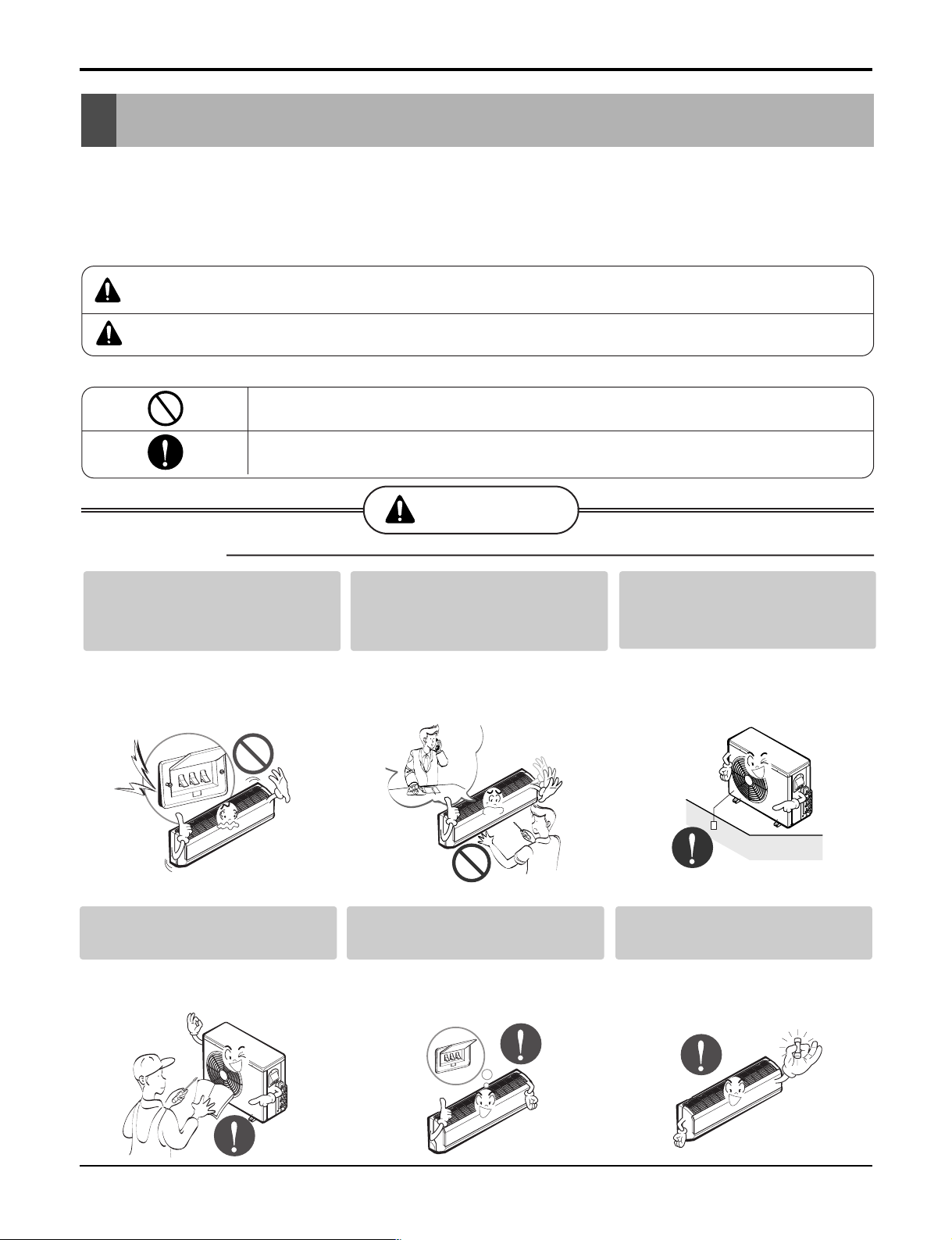
WARNING
Safety Precautions
To prevent injury to the user or other people and property damage, the following instructions must
be followed.
■ Incorrect operation due to ignoring instruction will cause harm or damage. The seriousness is
classified by the following indications.
This symbol indicates the possibility of death or serious injury.
This symbol indicates the possibility of injury or damage to properties only.
■ Meanings of symbols used in this manual are as shown below.
Be sure not to do.
Be sure to follow the instruction.
■ Installation
Do not use a defective or underrated circuit breaker. Use this
appliance on a dedicated circuit.
• There is risk of fire or electric
shock.
Install the panel and the cover
of control box securely.
• There is risk of fire or electric
shock.
For electrical work, contact the
dealer, seller, a qualified electrician,
or an Authorized Service Center
• Do not disassemble or repair the
product. There is risk of fire or
electric shock.
Always install a dedicated circuit and breaker.
• Improper wiring or installation may
cause fire or electric shock
.
Always ground the product.
• There is risk of fire or electric
shock.
Use the correctly rated breaker or fuse.
• There is risk of fire or electric
shock.
4 Multi type Air Conditioner
Safety Precautions
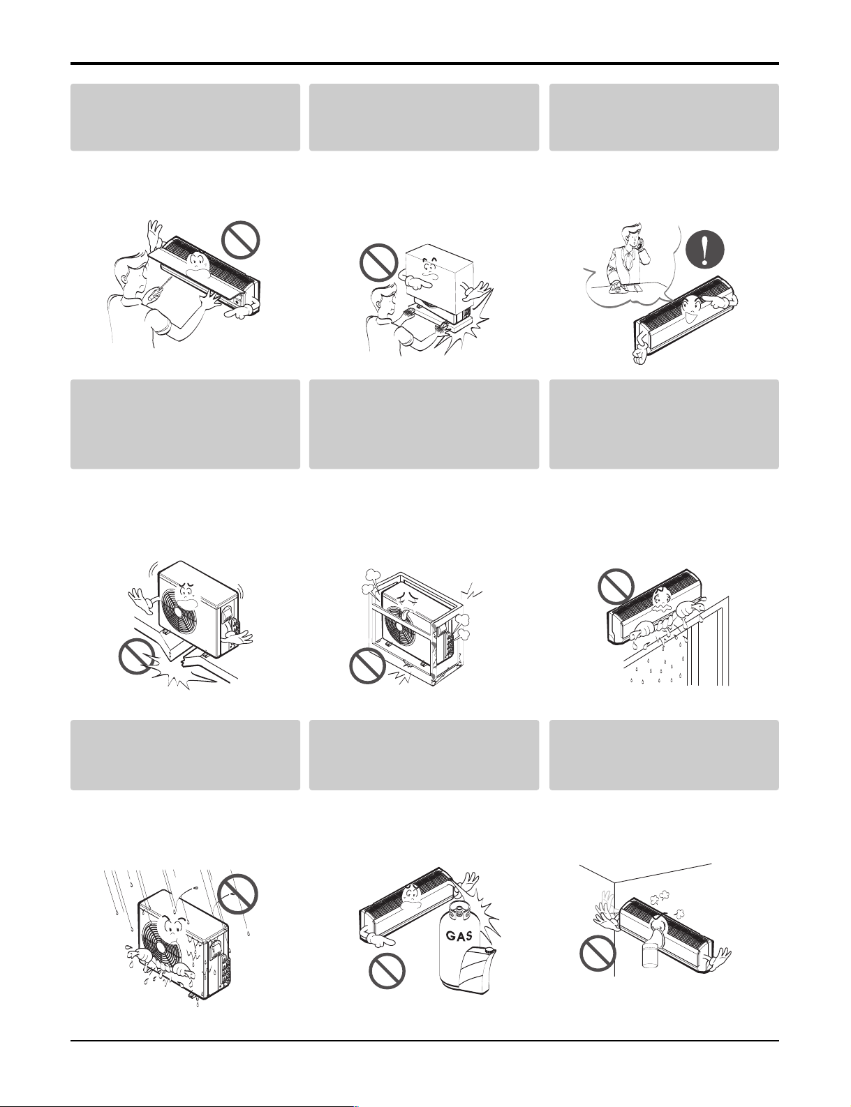
Do not install, remove, or reinstall the unit by yourself
(customer).
• There is risk of fire, electric shock,
explosion, or injury.
Do not install the product on a
defective installation stand.
• It may cause injury, accident, or
damage to the product.
Be cautious when unpacking
and installing the product.
• Sharp edges could cause injury.
Be especially careful of the case
edges and the fins on the condenser and evaporator.
Be sure the installation area
does not deteriorate with age.
• If the base collapses, the air conditioner could fall with it, causing
property damage, product failure,
and personal injury.
For installation, always contact the dealer or an
Authorized Service Center.
• There is risk of fire, electric shock,
explosion, or injury.
Do not let the air conditioner
run for a long time when the
humidity is very high and a
door or a window is left open.
• Moisture may condense and wet or
damage furniture.
Do not allow water to run into
electric parts.
• It may cause There is risk of fire,
failure of the product, or electric
shock.
Do not store or use flammable
gas or combustibles near the
product.
• There is risk of fire or failure of
product.
Gasolin
Do not use the product in a
tightly closed space for a long
time.
• Oxygen deficiency could occur.
Service Manual 5
Safety Precautions
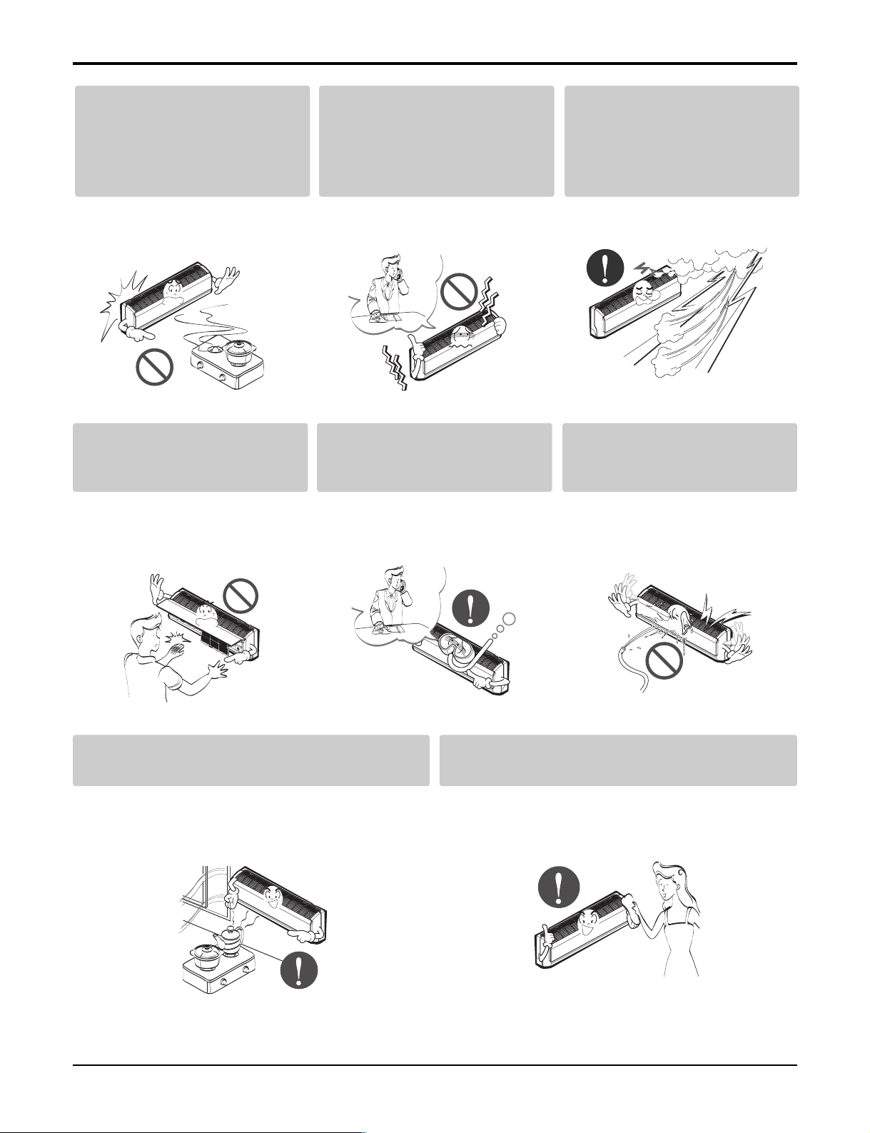
When flammable gas leaks,
turn off the gas and open a
window for ventilation before
If strange sounds, or smoke
comes from product. Turn the
breaker off.
turn the product on.
• Do not use the telephone or turn
switches on or off. There is risk of
explosion or fire
Do not open the inlet grill of the product
during operation. (Do not touch the electrostatic filter, if the unit is so equipped.)
• There is risk of physical injury,
electric shock, or product failure.
• There is risk of electric shock or
fire.
When the product is soaked
(flooded or submerged), contact
an Authorized Service Center.
• There is risk of fire or electric
shock.
Stop operation and close the
window in storm or hurricane.
If possible, remove the product from the window before
the hurricane arrives.
• There is risk of property damage,
failure of product, or electric shock.
Be cautious that water could
not enter the product.
• There is risk of fire, electric shock,
or product damage.
Ventilate the product from time to time when
operating it together with a stove, etc.
• There is risk of fire or electric shock.
6 Multi type Air Conditioner
Turn the main power off when cleaning or
maintaining the product.
• There is risk of electric shock.
Safety Precautions
CAUTION
When the product is not to be used for a long time,
disconnect the power by turning off the breaker.
• There is risk of product damage or failure, or unintended operation.
■ Installation
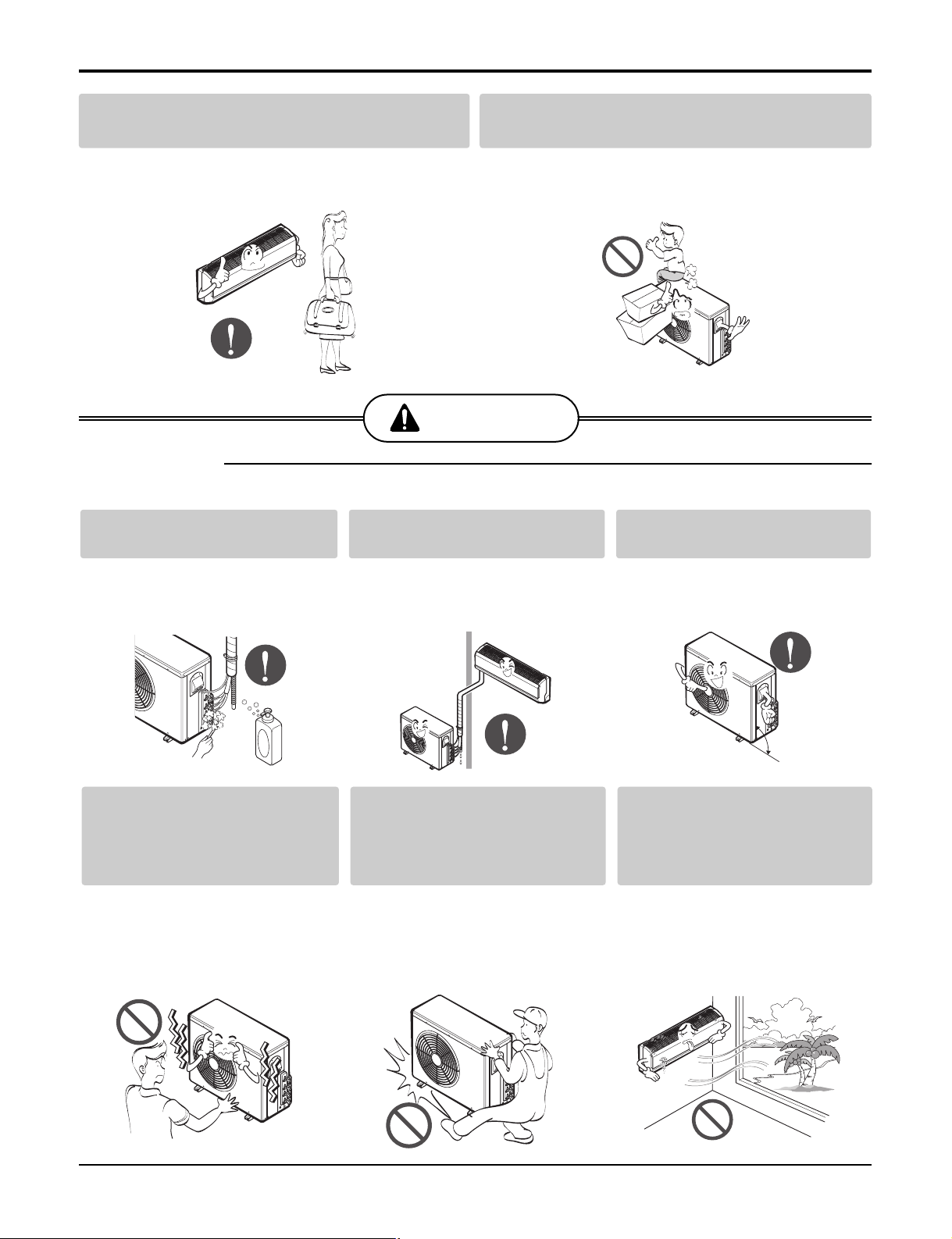
Always check for gas (refrigerant) leakage after installation or repair of product.
Install the drain hose to ensure that
water is drained away properly.
Take care to ensure that nobody could step on
or fall onto the outdoor unit.
• This could result in personal injury and product damage.
Keep level even when
installing the product.
• Low refrigerant levels may cause
failure of product.
Do not install the product
where the noise or hot air
from the outdoor unit could
oftend neighbors.
• It may cause a problem for your
neighbors.
• A bad connection may cause water
leakage.
Use two or more people to lift
and transport the product.
• Avoid personal injury.
• To avoid vibration or water leakage.
90°
Do not install the product
where it will be exposed to
sea wind (salt spray) directly.
• It may cause corrosion on the
product. Corrosion, particularly on
the condenser and evaporator fins,
could cause product malfunction or
inefficient operation.
Service Manual 7
Safety Precautions
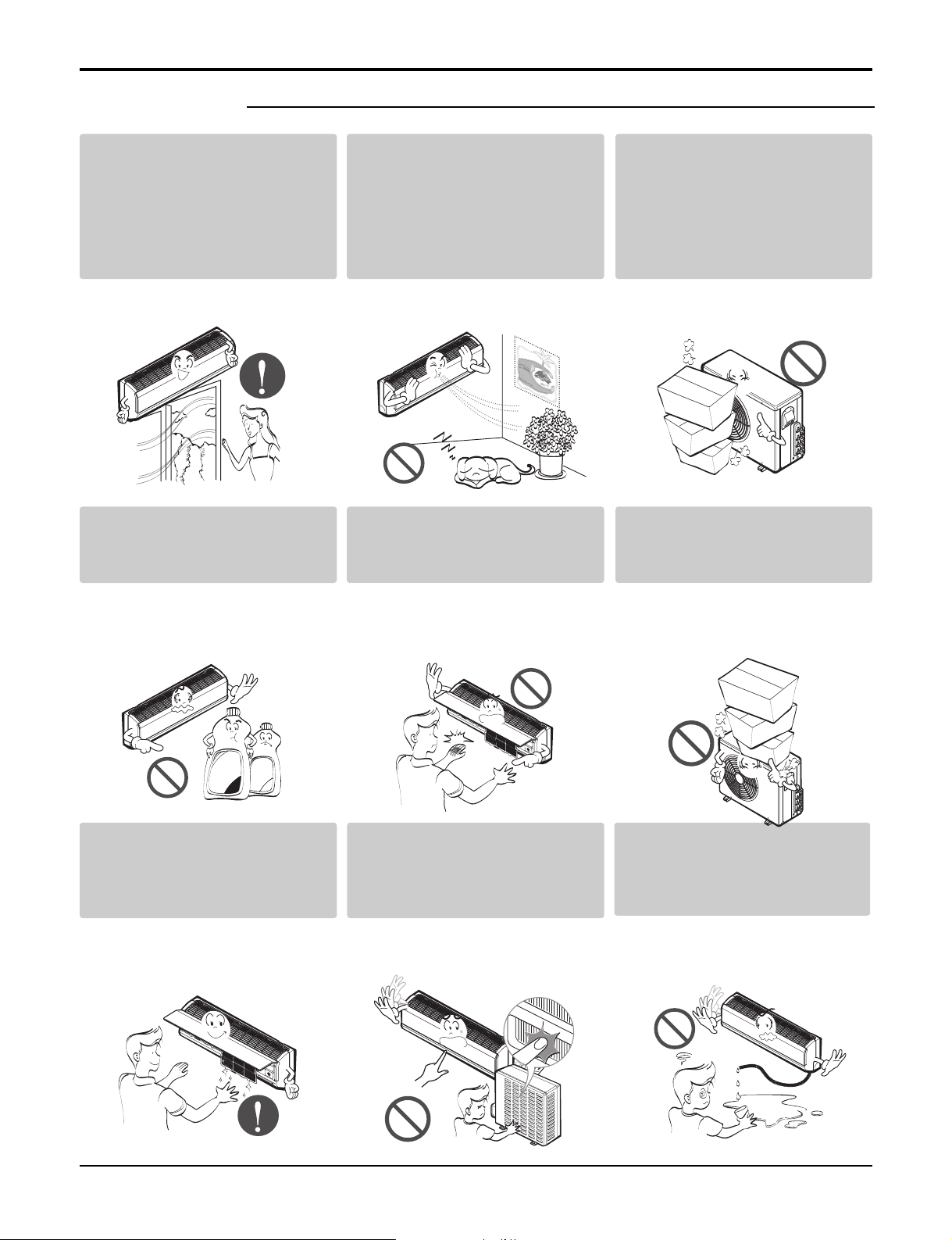
■ Operational
Do not expose the skin directly to cool air for long periods
of time.
(Don't sit in the draft.)
• This could harm to your health.
Use a soft cloth to clean. Do
not use harsh detergents, solvents, etc.
• There is risk of fire, electric shock,
or damage to the plastic parts of
the product.
Do not use the product for
special purposes, such as
preserving foods, works of
art, etc. It is a consumer air
conditioner, not a precision
refrigeration system.
• There is risk of damage or loss of
property.
Do not touch the metal parts of
the product when removing the
air filter. They are very sharp!
• There is risk of personal injury.
Do not block the inlet or outlet
of air flow.
• It may cause product failure.
Do not step on or put anyting
on the product. (outdoor
units)
• There is risk of personal injury and
failure of product.
Thinner
Wax
Always insert the filter securely. Clean the filter every two
weeks or more often if necessary.
•
A dirty filter reduces the efficiency of
the air conditioner and could cause
product malfunction or damage.
8 Multi type Air Conditioner
Do not insert hands or other
objects through the air inlet or
outlet while the product is
operated.
• There are sharp and moving parts
that could cause personal injury.
Do not drink the water drained
from the product.
• It is not sanitary and could cause
serious health issues.
Safety Precautions
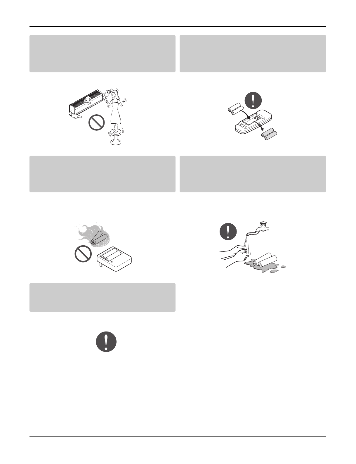
Use a firm stool or ladder when cleaning or
maintaining the product.
• Be careful and avoid personal injury.
Do not recharge or disassemble the batteries.
Do not dispose of batteries in a fire.
• They may burn or explode.
Replace the all batteries in the remote control
with new ones of the same type. Do not mix
old and new batteries or different types of batteries.
• There is risk of fire or explosion
If the liquid from the batteries gets onto your
skin or clothes, wash it well with clean water.
Do not use the remote if the batteries have
leaked.
• The chemicals in batteries could cause burns or other
health hazards.
If you eat the liquid from the batteries, brush
your teeth and see doctor. Do not use the
remote if the batteries have leaked.
• The chemicals in batteries could cause burns or other
health hazards.
Service Manual 9
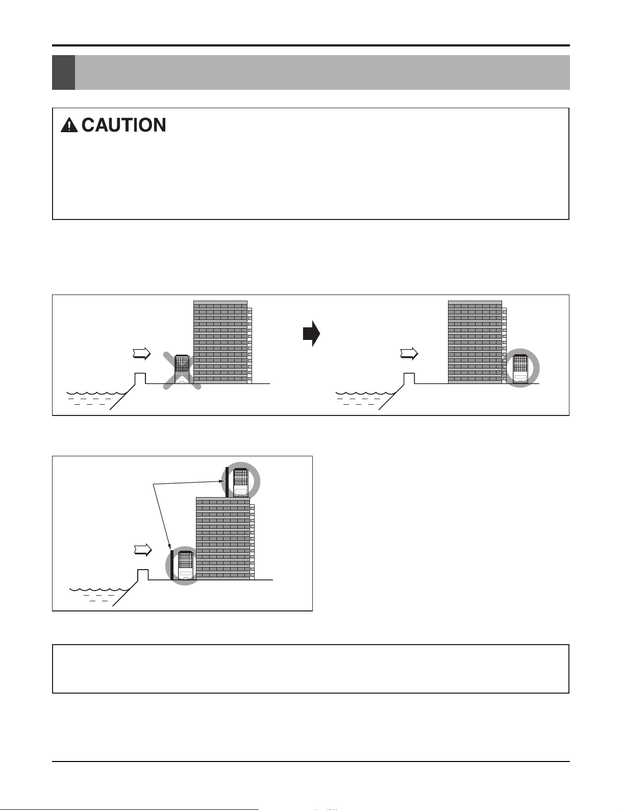
Installation guide at the seaside
Sea wind Sea wind
Installation guide at the seaside
1.
Air conditioners should not be installed in areas where corrosive gases, such as acid or alkaline gas, are produced.
2. Do not install the product where it could be exposed to sea wind (salty wind) directly. It can result corrosion
on the product. Corrosion, particularly on the condenser and evaporator fins, could cause product malfunction or inefficient performance.
3. If outdoor unit is installed close to the seaside, it should avoid direct exposure to the sea wind. Otherwise it
needs additional anticorrosion treatment on the heat exchanger.
Selecting the location(Outdoor Unit)
1) If the outdoor unit is to be installed close to the seaside, direct exposure to the sea wind should be avoided.
Install the outdoor unit on the opposite side of the sea wind direction.
2) In case, to install the outdoor unit on the seaside, set up a windbreak not to be exposed to the sea wind.
Windbreak
Sea wind
3) Select a well-drained place.
1.
If you can’t meet above guide line in the seaside installation, please contact LG Electronics for the additional anticorrosion treatment.
2. Periodic ( more than once/year ) cleaning of the dust or salt particles stuck on the heat exchanger by using water
• It should be strong enough like concrete to prevent
the sea wind from the sea.
• The height and width should be more than 150% of
the outdoor unit.
• It should be keep more than 70 cm of space
between outdoor unit and the windbreak for easy
air flow.
10 Multi type Air Conditioner
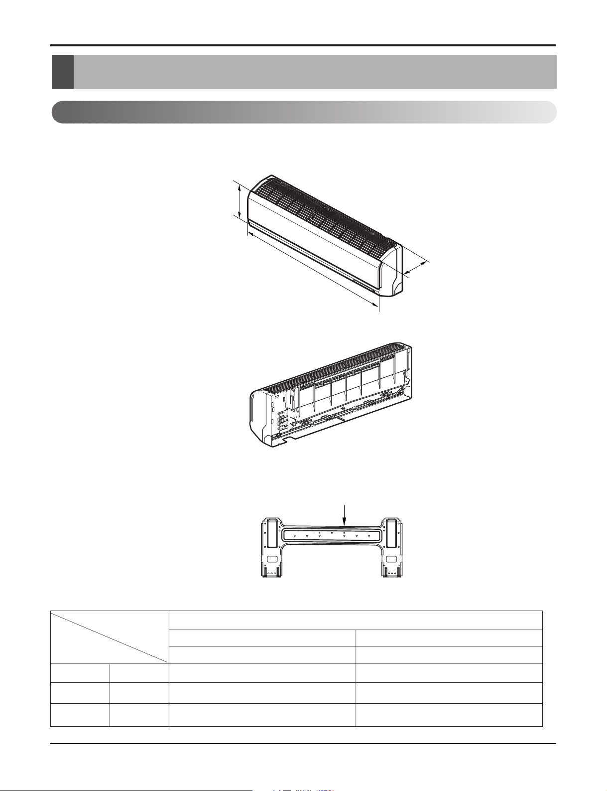
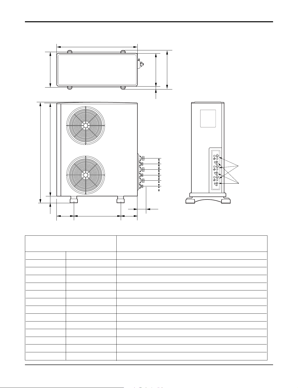
Dimensions
Installation plate
D
H
W
Indoor Unit
Split Type Indoor
Dimensions
Model
Dimension
W mm(in) 840(33) 895(35.2)
Split Type
S4
9 kBtu/h
SE
12 kBtu/h
H mm(in) 270(10.6) 282(11.1)
D mm(in) 153(6) 165(6.5)
Service Manual 11
W
D
L1
L2
L4
L3
H
L7L5L6
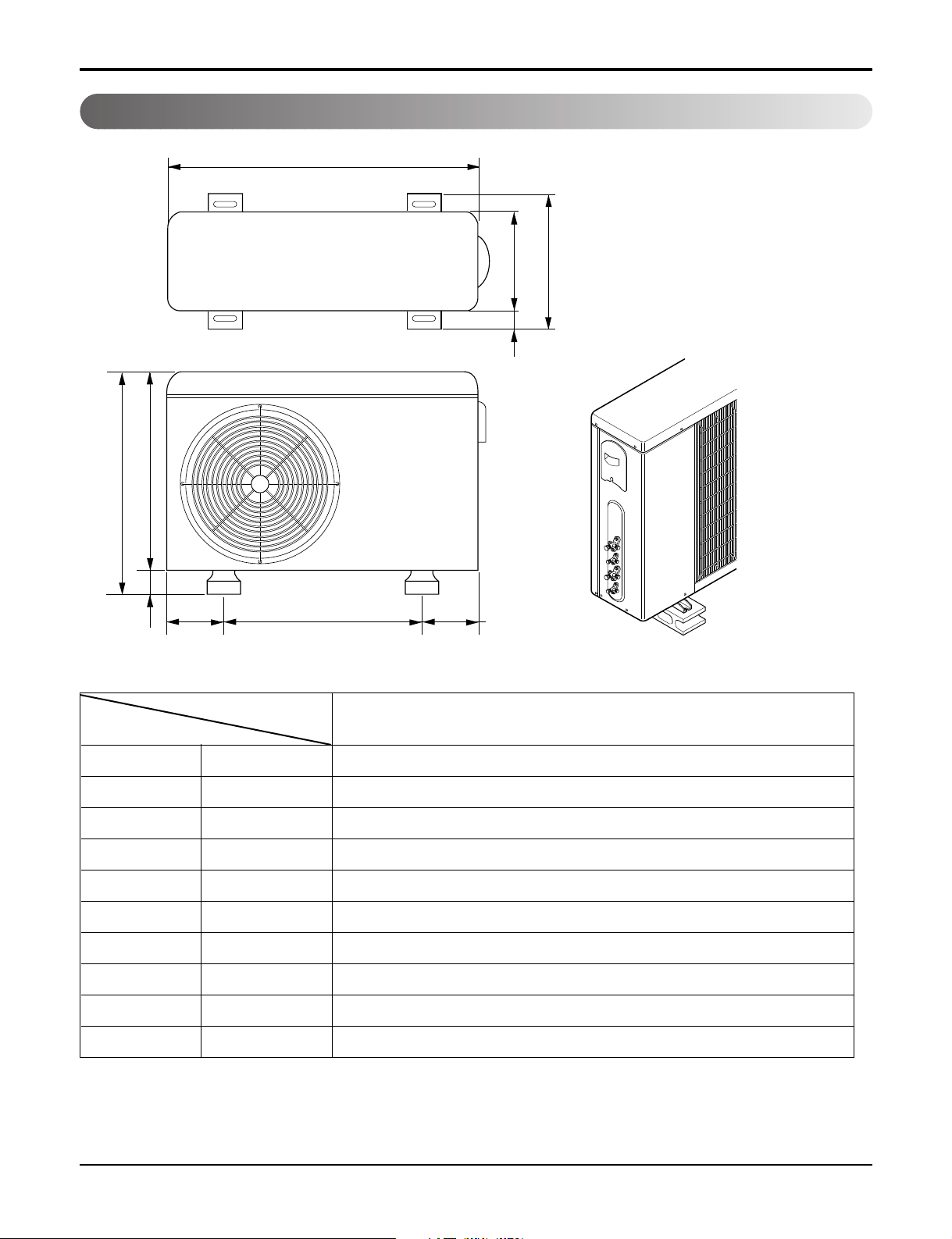
Dimensions
Outdoor Unit
MODEL
DIM
W mm(in) 870(34.3)
H mm(in) 655(25.8)
D mm(in) 320(12.6)
L1 mm(in) 370(14.6)
L2 mm(in) 25(1.0)
L3 mm(in) 775(30.5)
L4 mm(in) 25(1.0)
L5 mm(in) 546(21.5)
L6 mm(in) 160(6.3)
L7 mm(in) 160(6.3)
UE
18kBtu/h
12 Multi type Air Conditioner
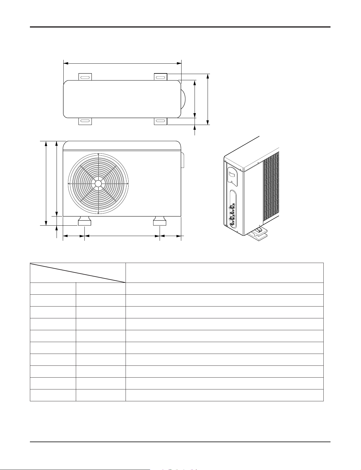
W
D
L1
L2
L4
L3
H
L7L5L6
MODEL
DIM
W mm(in) 870(34.3)
H mm(in) 808(31.8)
UE 1
24kBtu/h
D mm(in) 320(12.6)
L1 mm(in) 370(14.6)
L2 mm(in) 25(1.0)
L3 mm(in) 775(30.5)
L4 mm(in) 25(1.0)
L5 mm(in) 546(21.5)
L6 mm(in) 160(6.3)
L7 mm(in) 160(6.3)
Service Manual 13
Dimensions
L6L7 L8
L9
L4
H
L5
W
D
L1
L3
L2
L10 L11 L11 L11L11L11
Gas side
3-way valve
Liquid side
2-way valve
MODEL
DIM
W mm(in) 870(34.3)
H mm(in) 1038(40.7)
D mm(in) 320(12.6)
L1 mm(in) 360(14.2)
L2 mm(in) 340(13.4)
L3 mm(in) 25(1.0)
L4 mm(in) 1035(40.8)
L5 mm(in) 25(1.0)
L6 mm(in) 546(21.5)
L7 mm(in) 160(6.3)
L8 mm(in) 160(6.3)
L9 mm(in) 44(11.7)
L10 mm(in) 64.5(2.5)
L11 mm(in) 50(2.0)
UE2
36kBtu/h
14 Multi type Air Conditioner
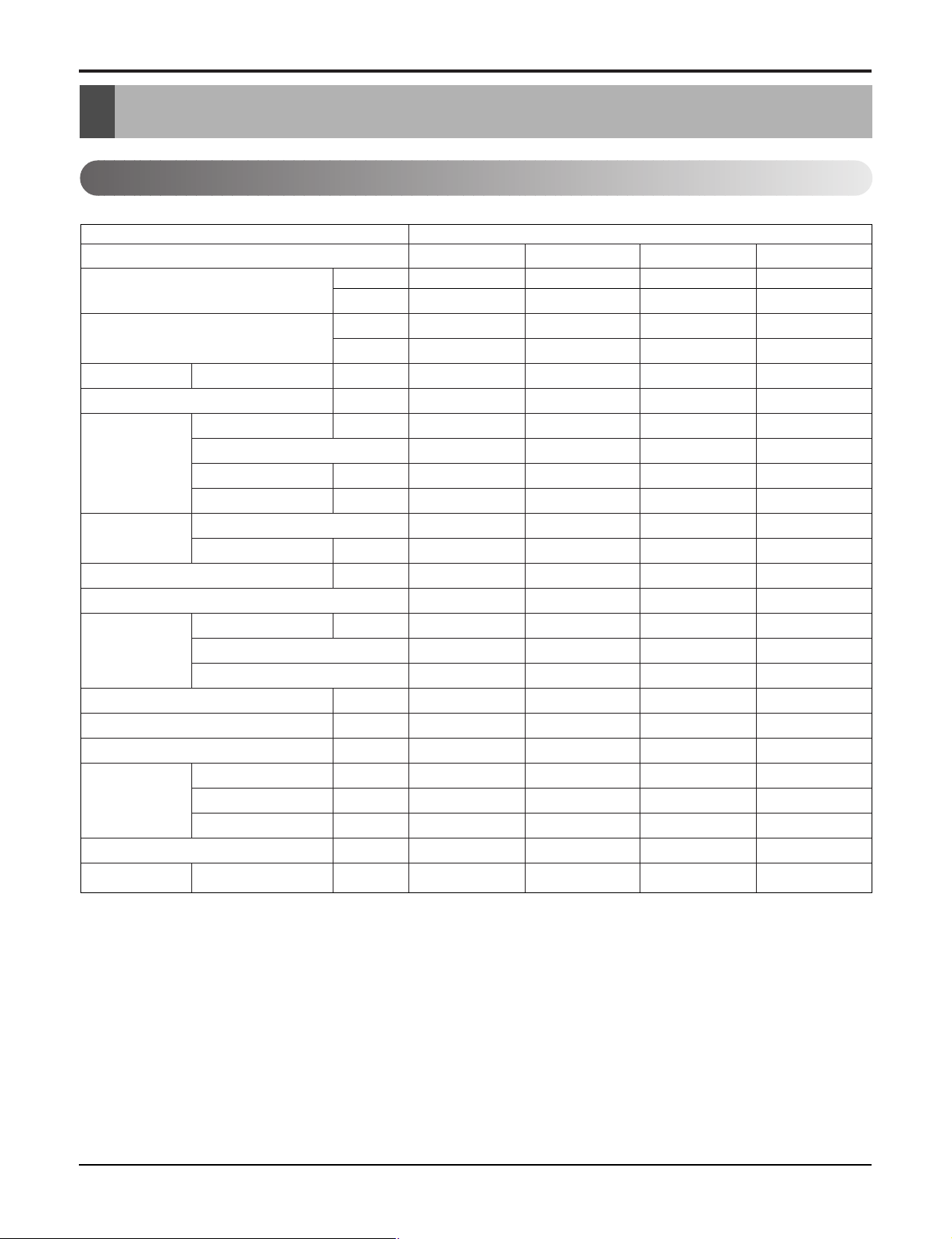
Product Specifications
Indoor Unit
Product Specifications
Indoor Unit Type
Model
Nominal Cooling Capacity kcal/h(W)
Nominal Heating Capacity kcal/h(W)
Air Circulation H/M/L CMM(CFM)
Setting temperature range(cool/heat) °C
Fan motor Output W
Fan Type
Noise Level (Sound Press,1m)
Temperature controller
Coil Tube Size (OD) inch(mm)
Dehumidification Rate l/h
Dimensions (W*H*D) inch(mm)
Net Weight kg(lbs)
Piping Connection Liquid inch(mm)
Packing Dimension (W*H*D) inch(mm)
Stuffing Quantity With(Without) S/Parts 20/40ft(hi-c)
★
Btu/h
★
Btu/h
Model
Input V
Running Current A
No. Used / Diameter EA/inch(mm)
H/M/L dBA
Fins per inch
No. of Rows & Column
Gas inch(mm)
Drain hose (ID Ø) mm
Wall Mounted
B-MMC09FA-1 B-MMH09FA-1 B-MMC12FA-1 B-MMH12FA-1
2,267(2,637) 2,267(2,637) 3,023(3,516) 3,023(3,516)
9,000 9,000 12,000 12,000
- 2,267(2,637) - 3,023(3,516)
- 9,000 - 12,000
8.2(289) 8.2(289) 9.4(332) 9.4(332)
18~30 18~30 18~30 18~30
15 15 15 15
DL-88430LGIF DL-88430LGIF DL-88430LGIF DL-88430LGIF
DC36 DC36 DC36 DC36
0.15 0.15 0.15 0.15
Cross Flow Fan Cross Flow Fan Cross Flow Fan Cross Flow Fan
1/3.74(95) 1/3.74(95) 1/3.74(95) 1/3.74(95)
31 / 29 / 22 31 / 29 / 22 36 / 32 / 29 36 / 32 / 29
Thermistor Thermistor Thermistor Thermistor
0.197(5.0) 0.197(5.0) 0.197(5.0) 0.197(5.0)
20 20 18 18
2R,15C 2R,15C 2R,15C 2R,15C
- 1.1 - 1.2
33.0*10.6*6.0(840*270*153) 33.0*10.6*6.0(840*270*153) 35.2*11.1*6.5(895*282*165) 35.2*11.1*6.5(895*282*165)
7(15.4) 7(15.4) 9.5(20.9) 9.5(20.9)
1/4 (6.35) 1/4 (6.35) 1/4 (6.35) 1/4 (6.35)
3/8 (9.52) 3/8 (9.52) 3/8 (9.52) 3/8 (9.52)
20 20 20 20
35.7*13.1*8.8(906*332*223) 35.7*13.1*8.8(906*332*223) 38.3*9.1*14.6(973*231*372) 38.3*9.1*14.6(973*231*372)
440/910 (1091) 440/910 (1091) 353/719 (792) 353/719 (792)
Note : 1.★See the page "Combination Table"
2. Due to our policy of innovation some specifications may be changed without notification.
Service Manual 15

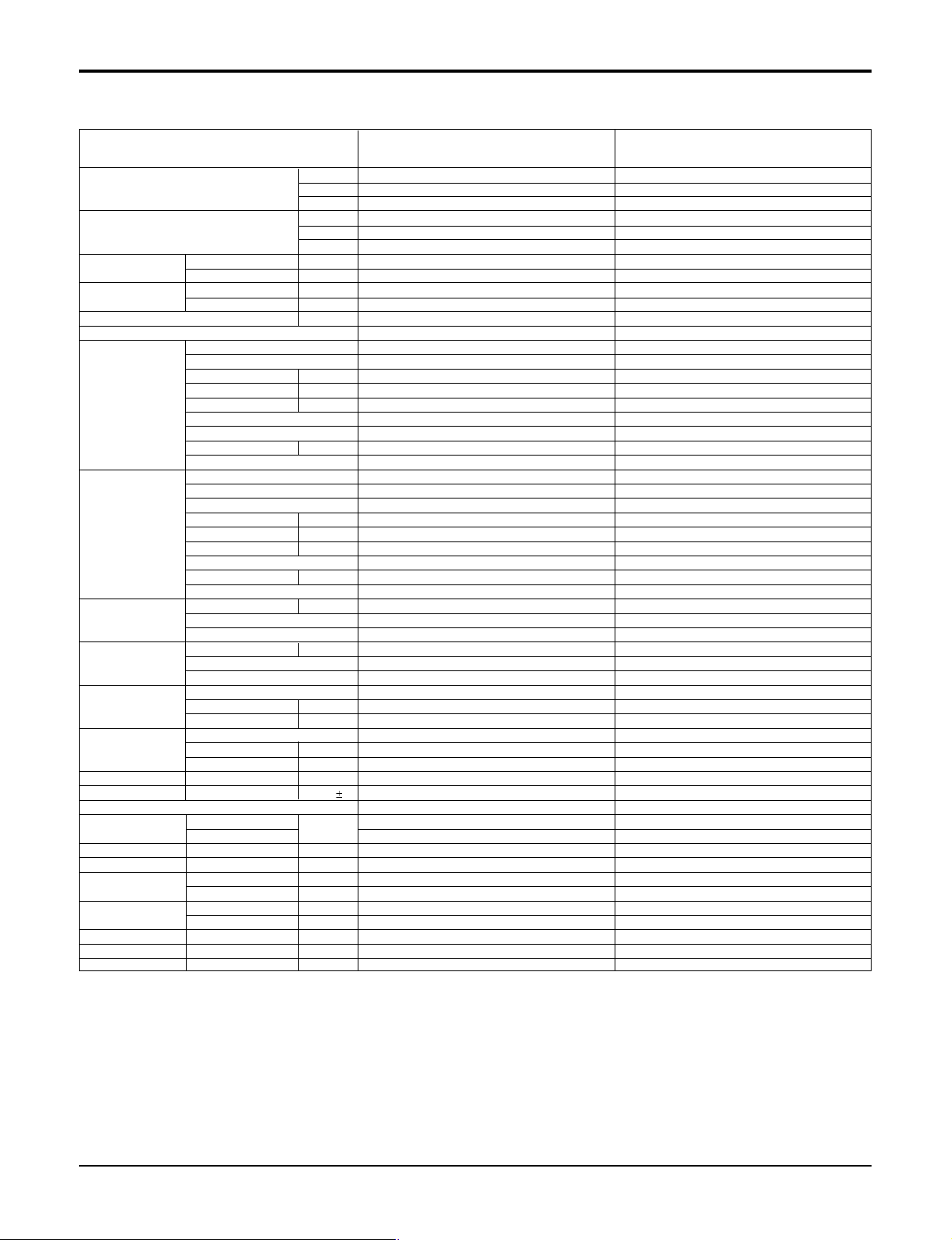
Product Specifications
Outdoor Unit - Multiple piping models
Model
Cooling Capacity★ Btu/hr
Heating Capacity★ Btu/hr
Input★ Cooling W
Running Current★(208/230V)
Power Supply Ø,V,Hz
Max. Number of Connectable Indoor Units
Compressor Type
(Constant) Model
Compressor Type
(Constant) Model
Refrigerant charge Charge g(oz)
Coil Tube Size (OD) inch(mm)
Fan motor Model
Fan Type
Air Circulation Outdoor CMM(CFM)
Noise Level(H/L) at 230V
Defrosting
SVC Valve Liquid inch(mm)
Dimensions W*H*D inch(mm)
Net Weight Outdoor kg(lbs)
Max. Interunit Piping Length
Max. Installation Indoor Unit~Outdoor Unit m
Height Difference Indoor Unit~Indoor Unit m
Packing Dimension W*H*D inch(mm)
Testing Combinations
Stuffing Quantity 20/40ft
Heating W
Cooling A
Heating A
Motor Type
Quantity Ea
Motor Input W
Oil Charge cc
Oil Type
Capacitor µF/Vac
O.L.P Type(model name)
Motor Type
Quantity Ea
Motor Input W
Oil Charge cc
Oil Type
Capacitor µF/Vac
O.L.P Type(model name)
Type
Control
Fins per inch
No. of Rows & Column/No.
Output W
Capacitor µF/Vac
No. Used / Diameter EA/inch(mm)
Discharge Side / Top
Sound Press,1m dB(A) 1
Gas
Total of Each Room m
For One Room m
W
kcal/hr
W
kcal/hr
A-MMH18FA-1
9,000~18,000
2637~5275
2267~4536
9,000~18,000
2637~5275
2267~4536
1070~1980
1040~1960
4.9~8.8
4.6~8.6
1,208/230,60
2
Rotary
GK094K
Hermetic
1
955
330±10
FVC68D
30 / 370
External Type(MRA98996-12026)
Rotary
GK113K
Hermetic
1
1,120
330±10
FVC68D
35 / 370
External Type(MRA12124-12026)
1400(49)
R410A
EEV
0.276(7.0)
18
2R,28C
IC-1640LG GE
90
6/370
Propeller
1 / 460
Side
50(1765.7)
51
Invertion Cycle
1/4 (6.35) * 2EA
3/8 (9.52) * 2EA
34.3*25.8*12.6 (870*655*320)
57(125.7)
30
15
7.5
7.5
40.2*28.2*17.2 (1020*716*437)
S4 9k + S4 9k
81/171
Note:
1. Capacities are based on the following conditions:
Cooling: - Indoor Temperature 26.7˚C(80˚F) DB/19.4˚C(67˚F) WB
- Outdoor Temperature 35˚C(95˚F) DB/23.9˚C(75˚F) WB
Heating: - Indoor Temperature 21.1˚C(70˚F) DB/15.6˚C(60˚F) WB
- Outdoor Temperature 8.3˚C(47˚F) DB/6.1˚C(43˚F) WB
Piping Length - Interconnecting Piping Length 7.5m
- Level Difference of Zero
16 Multi type Air Conditioner
2. Wiring cable size must comply with the applicable local and national code.
3. Capacities are Net Capacities.
4. ★: See the page "Combination Table"
5. The specification may be subject to change without prior notice for purpose
of improvement.
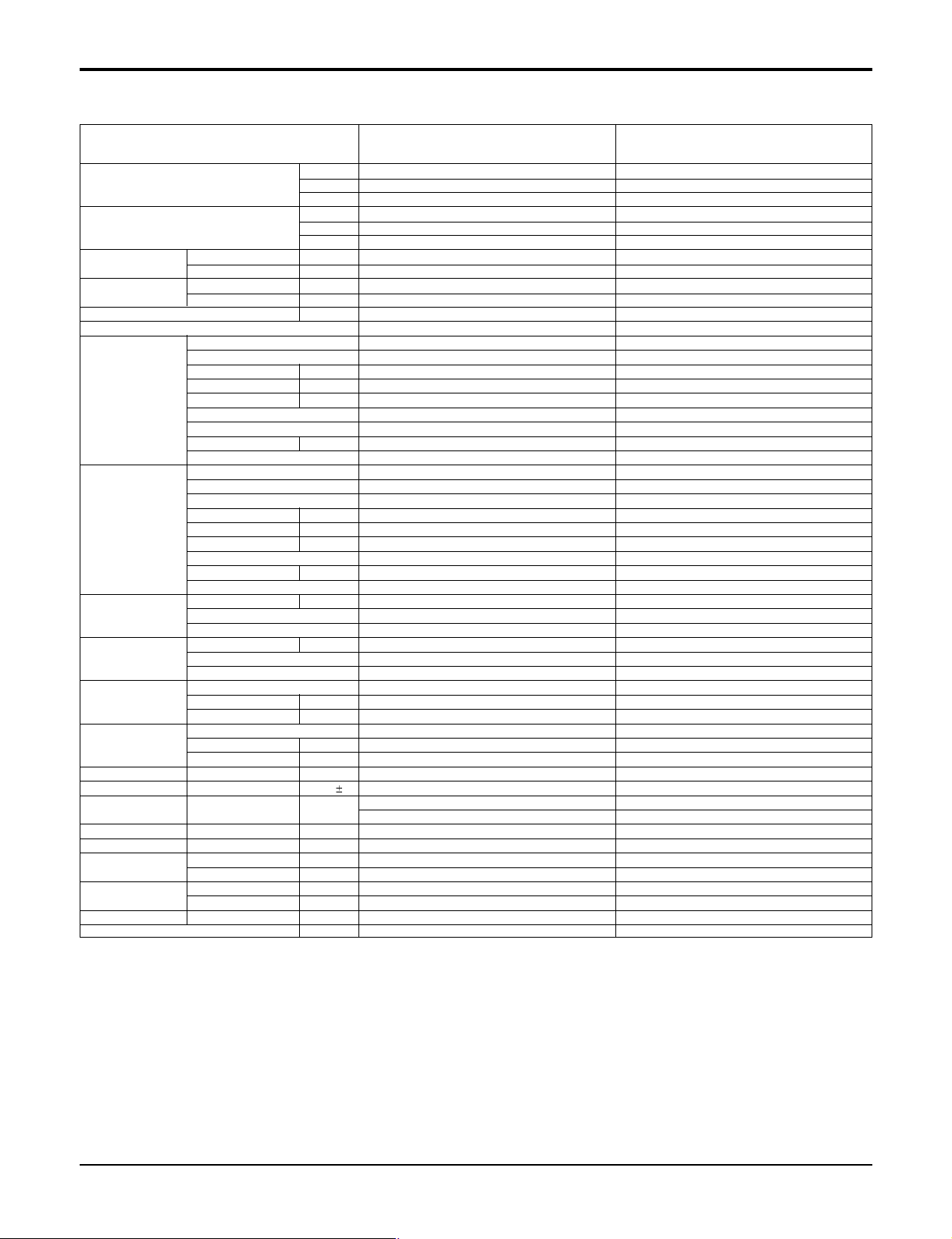
Product Specifications
Model
Cooling Capacity★ Btu/hr
Heating Capacity★ Btu/hr
Input★ Cooling W
Running Current★(208/230V)
Power Supply Ø,V,Hz
Max. Number of Connectable Indoor Units
Compressor Type
(Constant) Model
Compressor Type
(Constant) Model
Refrigerant charge Charge g(oz)
Coil Tube Size (OD) inch(mm)
Fan motor Model
Fan Type
Air Circulation Outdoor CMM(CFM)
Noise Level(H/L) at 230V
Defrosting
SVC Valve Liquid inch(mm)
Dimensions W*H*D inch(mm)
Net Weight Outdoor kg(lbs)
Max. Interunit Piping Length
Max. Installation Indoor Unit~Outdoor Unit m
Height Difference Indoor Unit~Indoor Unit m
Packing Dimension W*H*D inch(mm)
Testing Combinations
Stuffing Quantity 20/40ft
Heating W
Cooling A
Heating A
Motor Type
Quantity Ea
Motor Input W
Oil Charge cc
Oil Type
Capacitor µF/Vac
O.L.P Type(model name)
Motor Type
Quantity Ea
Motor Input W
Oil Charge cc
Oil Type
Capacitor µF/Vac
O.L.P Type(model name)
Type
Control
Fins per inch
No. of Rows & Column/No.
Output W
Capacitor µF/Vac
No. Used / Diameter EA/inch(mm)
Discharge Side / Top
Sound Press,1m dB(A) 1
Gas
Total of Each Room m
For One Room m
W
kcal/hr
W
kcal/hr
A-MMC24FA-1 A-MMH24FA-1
9,000~24,000 9,000~24,000
2637~7033 2637~7033
2267~6037 2267~6037
- 9,000~24,000
- 2637~7033
- 2267~6037
1170~2390 1170~2390
- 1220~2440
7.7~10.1 7.7~10.1
- 7.4~9.8
1,208/230,60 1,208/230,60
22
Rotary Rotary
GK094K GK094K
Hermetic Hermetic
11
955 955
330±10 330±10
FVC68D FVC68D
30 / 370 30 / 370
External Type(MRA98996-12026) External Type(MRA98996-12026)
Rotary Rotary
GK141K GK141K
Hermetic Hermetic
11
1430 1,430
350±10 350±10
FVE FVE
35 / 370 35 / 370
External Type(MRA12105-12026) External Type(MRA12105-12026)
1600 1600
R410A R410A
EEV EEV
0.276(7.0) 0.276(7.0)
18 18
2R,36C 2R,36C
IC-1640LG GE IC-1640LG GE
90 90
6/370 6/370
Propeller Propeller
1 / 460 1 / 460
Side Side
53(1872) 53(1872)
54 54
- Invertion Cycle
1/4 (6.35) * 2EA 1/4 (6.35) * 2EA
3/8 (9.52) * 2EA 3/8 (9.52) * 2EA
34.3*31.8*12.6 (870*808*320) 34.3*31.8*12.6 (870*808*320)
64(141.1) 64(141.1)
30 30
15 15
7.5 7.5
7.5 7.5
40.2*34.3*17.2 (1022*870*437) 40.2*34.3*17.2 (1022*870*437)
SE 12K +SE 12K SE 12K +SE 12K
54/114 54/114
Note:
1. Capacities are based on the following conditions:
Cooling: - Indoor Temperature 26.7˚C(80˚F) DB/19.4˚C(67˚F) WB
- Outdoor Temperature 35˚C(95˚F) DB/23.9˚C(75˚F) WB
Heating: - Indoor Temperature 21.1˚C(70˚F) DB/15.6˚C(60˚F) WB
- Outdoor Temperature 8.3˚C(47˚F) DB/6.1˚C(43˚F) WB
Piping Length - Interconnecting Piping Length 7.5m
- Level Difference of Zero
2. Wiring cable size must comply with the applicable local and national code.
3. Capacities are Net Capacities.
4. ★: See the page "Combination Table"
5. The specification may be subject to change without prior notice for purpose
of improvement.
Service Manual 17
Product Specifications
Model
Cooling Capacity★ Btu/hr
Heating Capacity★ Btu/hr
Input★ Cooling W
Running Current★(208/230V)
Power Supply Ø,V,Hz
Max. Number of Connectable Indoor Units
Compressor Type
(Constant) Model
Compressor Type
(Constant) Model
Refrigerant charge Charge g(oz)
Coil Tube Size (OD) inch(mm)
Fan motor Model
Fan Type
Air Circulation Outdoor CMM(CFM)
Noise Level(H/L) at 230V
SVC Valve Liquid inch(mm)
Dimensions W*H*D inch(mm)
Net Weight Outdoor kg(lbs)
Max. Interunit Piping Length
Max. Installation Indoor Unit~Outdoor Unit m
Height Difference Indoor Unit~Indoor Unit m
Packing Dimension W*H*D inch(mm)
Stuffing Quantity 20/40ft
Heating W
Cooling A
Heating A
Motor Type
Quantity Ea
Motor Input W
Oil Charge cc
Oil Type
Capacitor µF/Vac
O.L.P Type(model name)
Motor Type
Quantity Ea
Motor Input W
Oil Charge cc
Oil Type
Capacitor µF/Vac
O.L.P Type(model name)
Type
Control
Fins per inch
No. of Rows & Column/No.
Output W
Capacitor µF/Vac
No. Used / Diameter EA/inch(mm)
Discharge Side / Top
Sound Press,1m dB(A) 1
Gas
Total of Each Room m
For One Room m
W
kcal/hr
W
kcal/hr
A-MMC36FA-1 A-MMH36FA-1
9,000~36,000 9,000~36,000
2637~10,550 2637~10,550
2267~9071 2267~9071
- 9,000~36,000
- 2637~10,550
- 2267~9071
1320~3680 1320~3680
- 1410~3340
5.9~16.6 5.9~16.6
- 6.3~15.0
1,208/230,60 1,208/230,60
33
Rotary Rotary
GK141K GK141K
2 Pole Induction(PSC) 2 Pole Induction(PSC)
11
1430 1430
350Å}10 350Å}10
FVC68D FVC68D
35 / 370 35 / 370
External Type External Type
Rotary Rotary
GJ230K GJ230K
2 Pole Induction(PSC) 2 Pole Induction(PSC)
11
2370 2370
700±10 7000±10
FVC68D FVC68D
50 / 400 50 / 400
Internal Type Internal Type
2400 2400
R410A R410A
EEV EEV
0.276(7.0) 0.276(7.0)
18 18
2R,48C 2R,48C
ARC286B01 * 2 ARC286B01 * 2
102 102
2/370 2/370
Propeller Propeller
2 / 15.7(400) 2 / 15.7(400)
Side Side
63(2225) 63(2225)
51 51
1/4 (6..35) * 3EA 1/4 (6..35) * 3EA
3/8 (9.52) * 3EA 3/8 (9.52) * 3EA
34.3*40.7*12.6 (870*1038*320) 34.3*40.7*12.6 (870*1038*320)
84(185.2) 84(185.2)
45 45
15 15
7.5 7.5
7.5 7.5
41.3*44.9*17.3 (1048*1140*439) 41.3*44.9*17.3 (1048*1140*439)
53/111 53/111
Note:
1. Capacities are based on the following conditions:
Cooling: - Indoor Temperature 26.7˚C(80˚F) DB/19.4˚C(67˚F) WB
- Outdoor Temperature 35˚C(95˚F) DB/23.9˚C(75˚F) WB
Heating: - Indoor Temperature 21.1˚C(70˚F) DB/15.6˚C(60˚F) WB
- Outdoor Temperature 8.3˚C(47˚F) DB/6.1˚C(43˚F) WB
Piping Length - Interconnecting Piping Length 7.5m
- Level Difference of Zero
18 Multi type Air Conditioner
2. Wiring cable size must comply with the applicable local and national code.
3. Capacities are Net Capacities.
4. ★: See the page "Combination Table"
5. The specification may be subject to change without prior notice for purpose
of improvement.
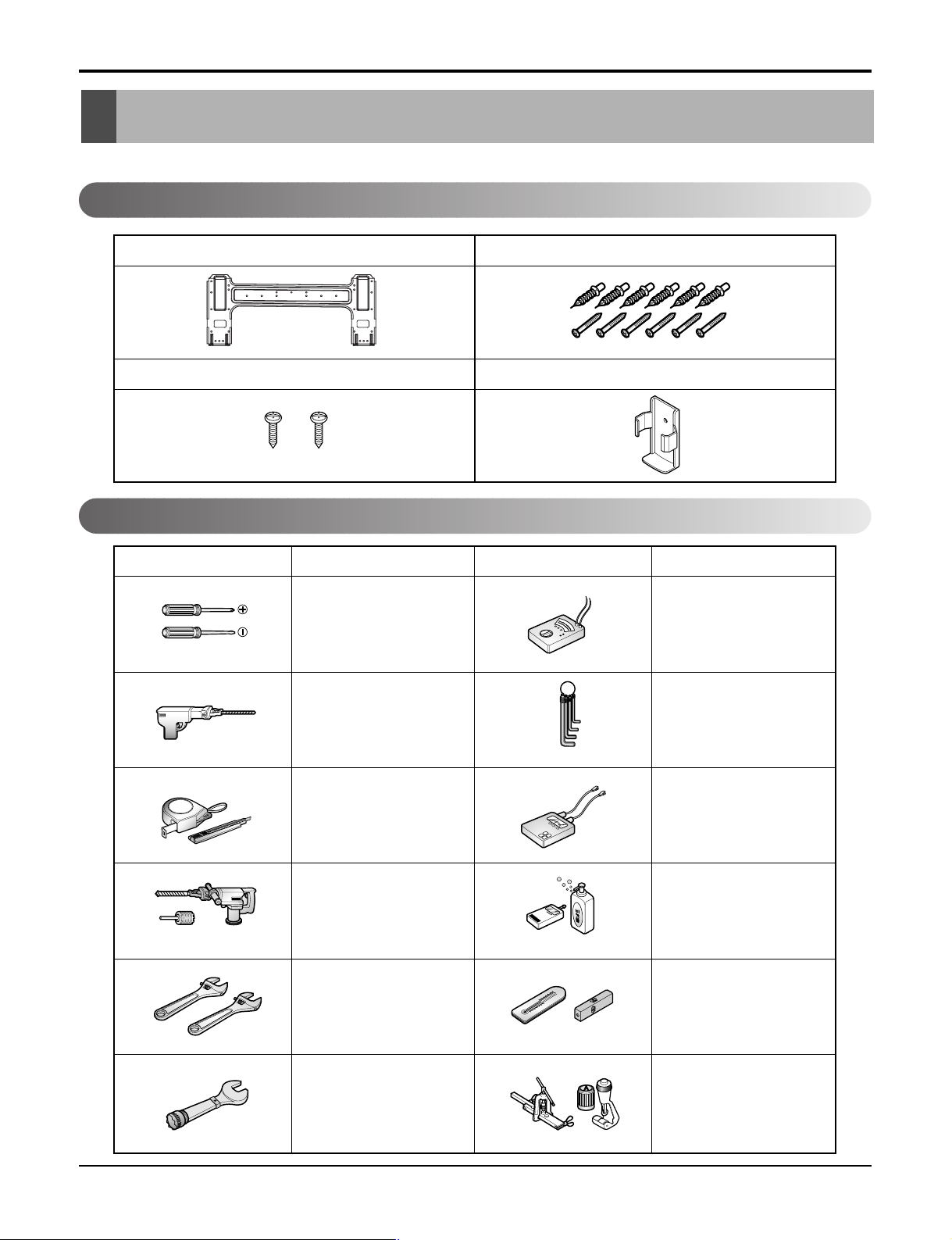
Installation
Type "A" screw and plastic anchor
Type "B" screw
Remote Control Holder
Installation plate
Figure FigureName
Screw driver
Electric Drill
Measuring Tape, Knife
Hole Core Drill
Spanner
Torque wrench
Ohmmeter
Hexagonal wrench
Ammeter
Gas Leak Detector
Thermometer,
Level
Flaring Tool Set
Name
Read carefully, and then follow step by step.
Installation Parts
Installation
Installation Tools
Service Manual 19
Installation
More than 20 cm
(7.9 inch)
More than 10 cm
(3.9 inch)
More than 10 cm
(3.9 inch)
More than 2.4m
(8 ft)
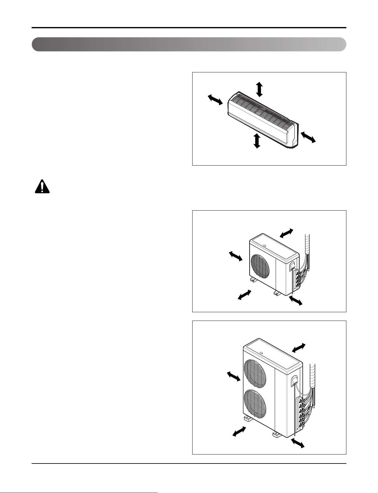
Select the best location
Indoor unit
1. Do not have any heat or steam near the unit.
2. Select a place where there are no obstacles in front
of the unit.
3. Make sure that condensation drainage can be conveniently routed away.
4. Do not install near a doorway.
5. Ensure the spaces indicated by arrows from the wall,
ceiling, fence or other obstacles.
6. Use a Metal Detector or Metal Scanner to locate
studs to prevent unnecessary damage to the wall.
CAUTION: Install the indoor unit
on the wall where the height from
the floors more than 2.4 m (8 ft).
Outdoor unit
1. If an awning is built over the unit to prevent direct
sunlight or rain exposure, make sure that heat radiation from the condenser is not restricted.
2. Ensure that the spaces indicated by arrows around
front, back and side of the unit.
3. Do not place animals and plants in the path of the
warm air.
4. Take the air conditioner weight into account and
select a place where noise and vibration are minimum.
Select a place so that the warm air and sound from
5.
the air conditioner do not disturb neighbors.
Rooftop Installations:
If the outdoor unit is installed on a roof structure, be
sure to level the unit. Ensure the roof structure and
anchoring method are adequate for the unit location.
Consult local codes regarding rooftop mounting.
18 / 24 kBtu
more than 30 cm
(11.8 inch)
more than 70 cm
(27.6 inch)
36 kBtu
more than 30 cm
(11.8 inch)
more than 30 cm
(11.8 inch)
more than 60 cm
(23.6 inch)
more than 30 cm
(11.8 inch)
20 Multi type Air Conditioner
more than 70 cm
(27.6 inch)
more than 60 cm
(23.6 inch)
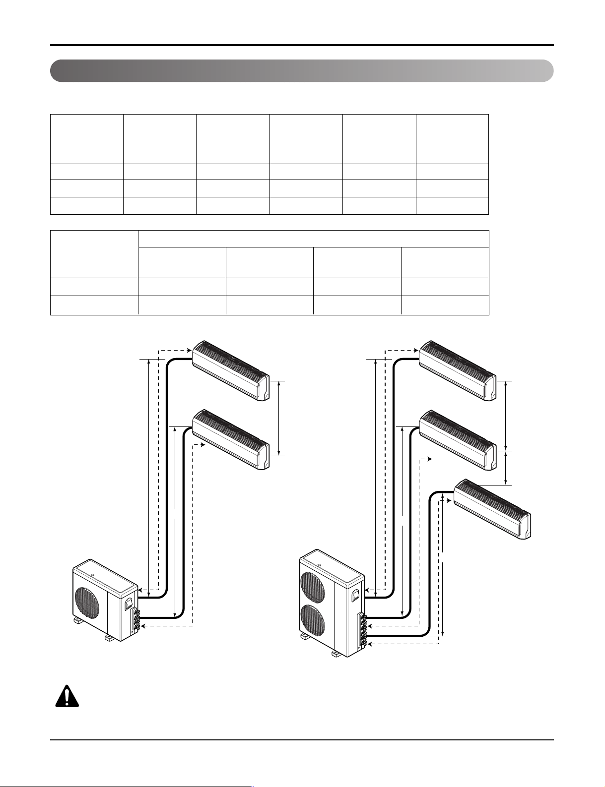
Piping length and elevation
h2
h2
h1
A
B
B
C
h2
h1
A
B
h1
h1
h1
Multi Piping Type
Installation
Capacity
Max total length
of all pipes
(A+B/A+B+C)
Max length of
each pipe
(A/B/C)
Min length of
each pipe
(A/B/C)
Max Elevation
between each
indoor unit and
outdoor unit (h1)
Max elevation
between indoor
units (h2)
18 kBtu 30 m (100 ft) 15 m (50 ft) 3 m (10 ft) 7.5 m (25 ft) 7.5 m (25 ft)
24 kBtu 30 m (100 ft) 15 m (50 ft) 3 m (10 ft) 7.5 m (25 ft) 7.5 m (25 ft)
36 kBtu 45 m (150 ft) 15 m (50 ft) 3 m (10 ft) 7.5 m (25 ft) 7.5 m (25 ft)
Pipe Size
Indoor Capacity
Gas Liquid Standard Length
Additional
Refrigerant
9 kBtu 9.52 mm (3/8") 6.35 mm (1/4") 7.5 m (25 ft) 20 g/m (0.22 oz/ft)
12 kBtu 9.52 mm (3/8") 6.35 mm (1/4") 7.5 m (25 ft) 20 g/m (0.22 oz/ft)
18 / 24 kBtu
36 kBtu
CAUTION: Capacity is based on standard length and maximum allowance length is on the
basis of reliability.
Service Manual 21
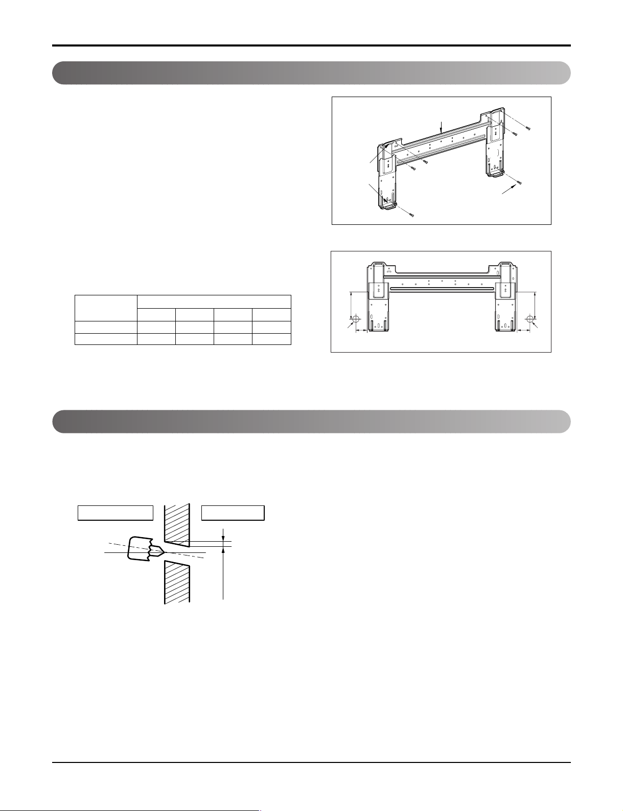
Installation
Installation Plate
Type "A" screw
Chassis
Hook
5-7 mm
(0.2"~0.3")
Indoor
WALL
Outdoor
Fixing Installation Plate(Standard Type)
The wall you select should be strong and solid enough to
prevent vibration
1. Mount the installation plate on the wall with
type "A" screws. If mounting the unit on a concrete wall,
use anchor bolts.
• Mount the installation plate horizontally by aligning the
centerline using a level.
2. Measure the wall and mark the centerline. It is also
important to use caution concerning the location of the
installation plate-routing of the wiring to power outlets is
through the walls typically. Drilling the hole through the
wall for piping connections must be done safely.
CHASSIS
(Grade)
S4 50 105 59 105
SE 65 110 85 110
ABCD
Distance (mm)
D
C
Ø70mm
Left rear piping Right rear piping
Installation plate
B
A
Ø70mm
Drill a hole in the wall
• Drill the piping hole with a Ø 70 mm (Ø 2.75 inch) hole core drill. Drill the piping hole at either the right or the left
with the hole slightly slanted to the outdoor side.
22 Multi type Air Conditioner
Flaring Work and Connection of Piping
Copper
pipe
90°
Slanted Uneven Rough
Bar
Copper pipe
Clamp handle
Red arrow mark
Cone
Yoke
Handle
Bar
"A"
Flaring Work and Connection of Piping
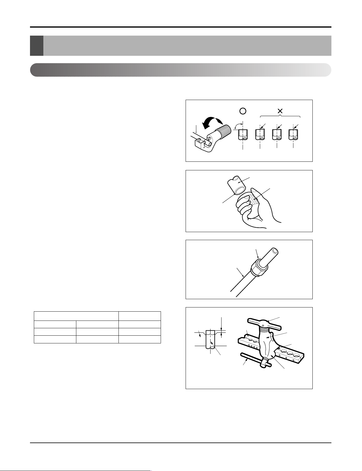
Flaring work
Main cause for gas leakage is due to defect in flaring work. Carry out correct flaring work in the following procedure.
Cut the pipes
1. Use the piping kit accessory or the pipes purchased locally.
2. Measure the distance between the indoor and the outdoor unit.
3. Cut the pipes a little longer than measured distance.
4. Cut the cable 1.5m (5.0ft) longer than the pipe length.
Burrs removal
1. Completely remove all burrs from the cut cross section of
pipe/tube.
2. Put the end of the copper tube/pipe in a downward direction
as you remove burrs in order to avoid dropping burrs into the
tubing.
Pipe
Reamer
Putting nut on
• Remove flare nuts attached to indoor and outdoor unit, then
put them on pipe/tube having completed burr removal.
(not possible to put them on after flaring work)
Flaring work
• Carry out flaring work using flaring tool as shown below.
• Firmly hold copper pipe in a Bar in the dimension shown in the
table Below.
Outside diameter A
mm inch mm
Ø6.35 1/4 0~0.5
Ø9.52 3/8 0~0.5
Point down
Flare nut
Copper tube
Service Manual 23
Flaring Work and Connection of Piping
Inclined
Inside is shiny without scratches
Smooth all round
Even length
all round
Surface
damaged
Cracked Uneven
thickness
= Improper flaring =
Check
1. Compare the flared work with the figure by.
2. If a flared section is defective, cut it off and do flaring work
again.
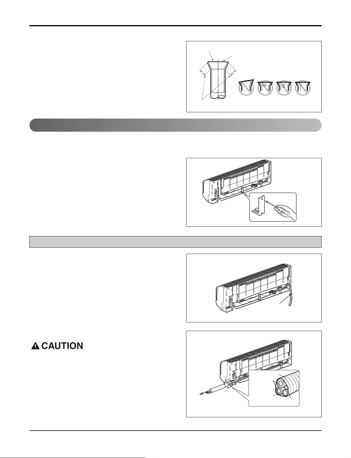
Connecting the Piping
Indoor
1. Prepare the indoor unit's piping and drain hose for installation through the wall.
2. Remove the plastic tubing retainer(see the illustration by)
and pull the tubing and drain hose away from chassis.
3. Replace only the plastic tubing holder 1, not the holder 2 in
the original position.
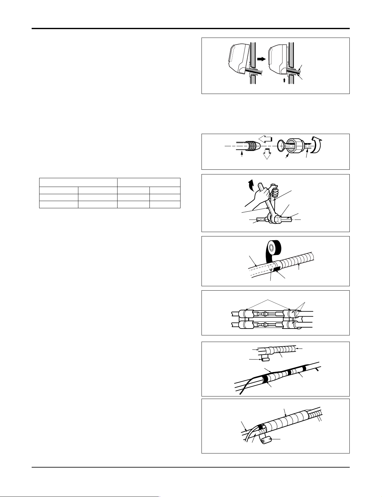
For right rear piping
1. Route the indoor tubing and the drain hose in the direction
of rear right.
2.
Insert the connecting cable into the indoor unit from the outdoor unit through the piping hole.
• Do not connect the cable to the indoor unit.
•
Make a small loop with the cable for easy connection later.
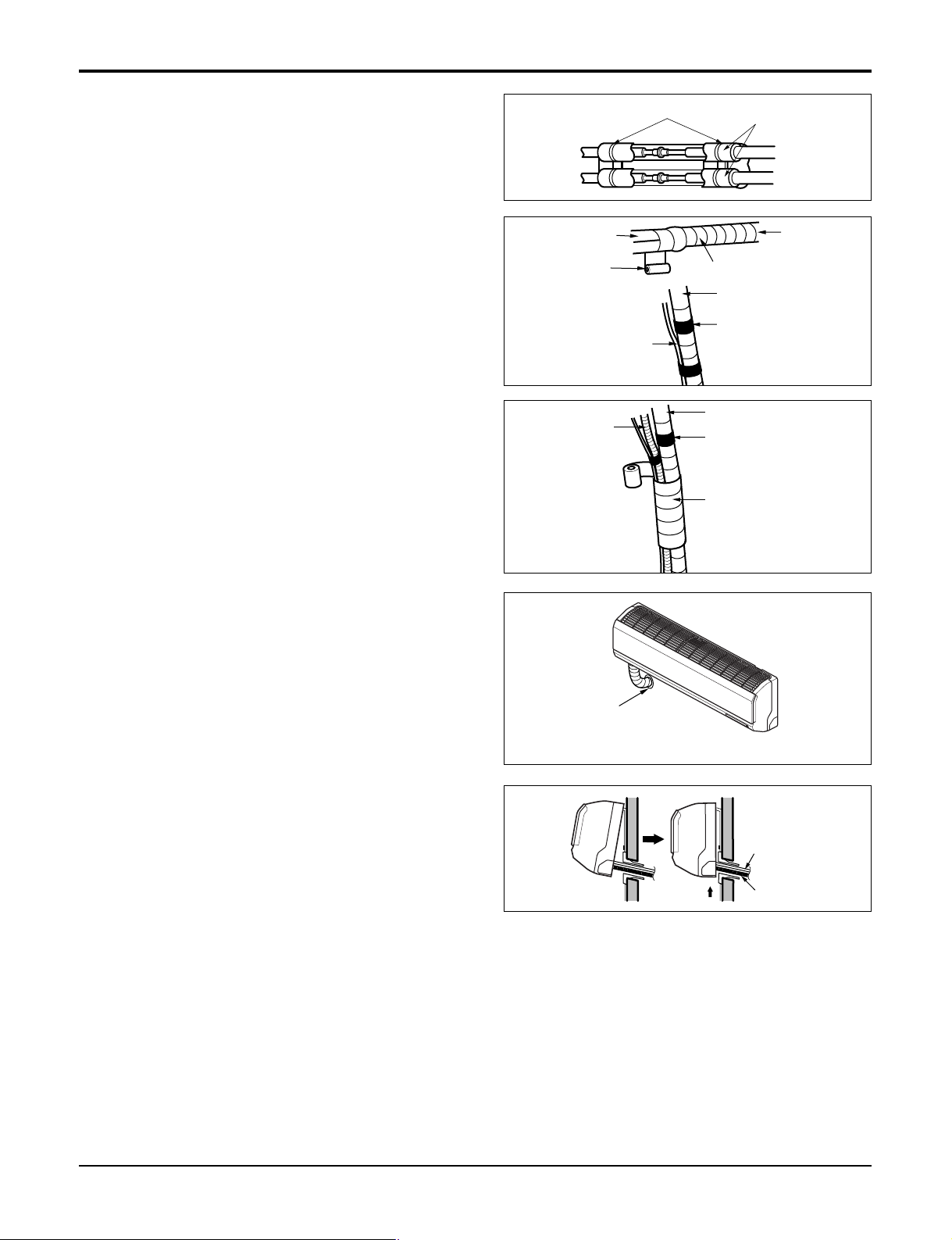
3. Tape the tubing, drain hose, and the connecting cable. Be
sure that the drain hose is located at the lowest side of the
bundle. Locating at the Upper side can cause drain pan to
overflow inside the unit.
If the drain hose is routed inside the room, insulate the hose
with an insulation material* so that dripping from "sweating"(condensation) will not damage furniture or floors.
*Foamed polyethylene or equivalent is recommended.
Drain hose
Tape
Connecting
pipe
Drain hose
Connecting cable
24 Multi type Air Conditioner
4. Indoor unit installation
Drain hose
Connecting
cable
Hook the indoor unit onto the upper portion of the installation plate.(Engage the two hooks of the rear top of the
indoor unit with the upper edge of the installation plate.)
Ensure that the hooks are properly seated on the installation plate by moving it left and right.
Press the lower left and right sides of the unit against the
installation plate until the hooks engage into their
slots(clicking sound).
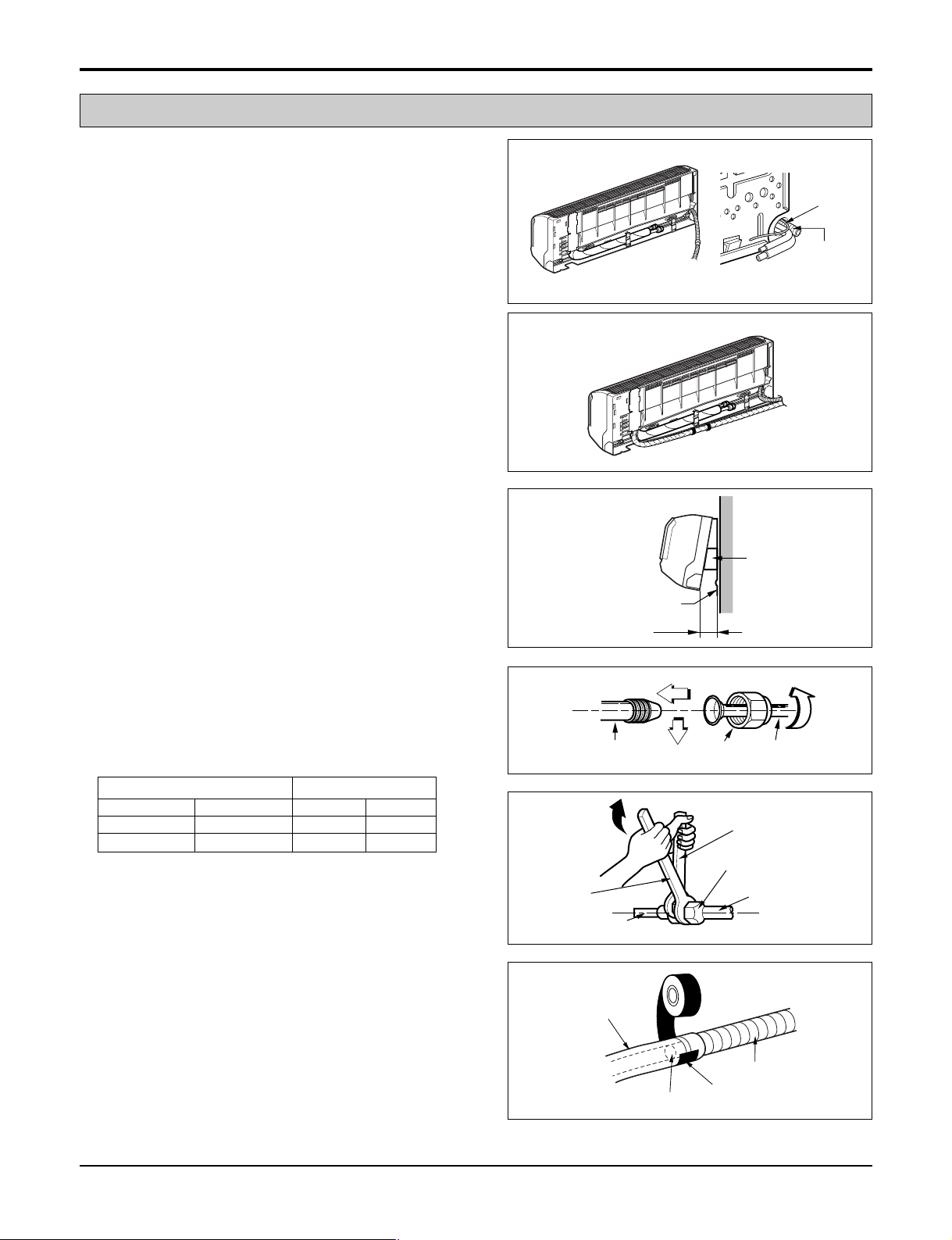
Connecting the piping to the indoor unit and drain hose
to drain pipe.
1. Align the center of the pipes and sufficiently tighten the
flare nut by hand.
2. Tighten the flare nut with a wrench.
Flaring Work and Connection of Piping
Indoor unit tubing Flare nut Pipes
Outside diameter Torque
mm inch kg.m lbf.in
Ø6.35 1/4 1.8 156.2
Ø9.52 3/8 4.2 364.5
3. When extending the drain hose at the indoor unit, install
the drain pipe.
Wrap the insulation material around the connecting portion.
1. Overlap the connection pipe insulation material and the
indoor unit pipe insulation material. Bind them together
with vinyl tape so that there may be no gap.
2. Wrap the area which accommodates the rear piping housing section with vinyl tape.
3. Bundle the piping and drain hose together by wrapping
them with vinyl tape for enough to cover where they fit into
the rear piping housing section.
Wrench
Indoor unit tubing
Drain pipe
Connection pipe
Vinyl tape (wide)
Connecting cable
Open-end wrench (fixed)
Flare nut
Indoor unit drain hose
Vinyl tape(narrow)
Adhesive
Plastic bands
Insulation material
Wrap with vinyl tape
Vinyl tape(narrow)
Connection pipe
Indoor unit pipe
Pipe
Wrap with vinyl tape
Pipe
Vinyl tape(wide)
Drain hose
Service Manual 25
Flaring Work and Connection of Piping
For left rear piping
1. Route the indoor tubing and the drain hose to the required
piping hole position.
2. Insert the piping, drain hose, and the connecting cable into
the piping hole.
3.
Insert the connecting cable into the indoor unit.
• Don't connect the cable to the indoor unit.
• Make a small loop with the cable for easy connection
later.
4. Tape the drain hose and the connecting cables.
5. Indoor unit installation
• Hang the indoor unit from the hooks at the top of the
installation plate.
• Insert the spacer etc. between the indoor unit and the
installation plate and separate the bottom of the indoor
unit from the wall.
Connecting the piping to the indoor unit and the drain
hose to drain pipe.
1. Align the center of the pipes and sufficiently tighten the
flare nut by hand.
Connecting
cable
Drain pipe
Indoor unit
Spacer
Installation plate
8cm
2. Tighten the flare nut with a wrench.
Outside diameter Torque
mm inch kg.m lbf.in
Ø6.35 1/4 1.8 156.2
Ø9.52 3/8 4.2 364.5
3. When extending the drain hose at the indoor unit, install
the drain pipe.
26 Multi type Air Conditioner
Indoor unit tubing Flare nut Pipes
Open-end wrench (fixed)
Flare nut
Wrench
Indoor unit tubing
Drain hose
Indoor unit drain hose
Adhesive
Vinyl tape
Connection pipe
(narrow)
Wrap the insulation material around the connecting por-
Plastic bands
Insulation material
tion.
1. Overlap the connection pipe heat insulation and the indoor
unit pipe heat insulation material. Bind them together with
vinyl tape so that there may be no gap.
2. Wrap the area which accommodates the rear piping housing section with vinyl tape.
3. Bundle the piping and drain hose together by wrapping
them with cloth tape over the range within which they fit
into the rear piping housing section.
Reroute the pipings and the drain hose across the back
of the chassis.
Flaring Work and Connection of Piping
Connection
pipe
Vinyl tape
(wide)
Connecting cable
Drain hose
Wrap with vinyl tape
Pipe
Vinyl tape(narrow)
Pipe
Vinyl tape(narrow)
Wrap with
vinyl tape(wide)
Indoor
unit piping
Indoor unit installation
1. Remove the spacer.
2. Ensure that the hooks are properly seated on the installation plate by moving it left and right.
3. Press the lower left and right sides of the unit against the
installation plate until the hooks engage into their
slots(clicking sound).
Piping for
passage through
piping hole
Connecting
cable
Drain hose
Service Manual 27
 Loading...