

LG B42AWYU362 Installation Manual

LG
Air Conditioner
INSTALLATION MANUAL
LG
Type : Ceiling Concealed Duct
IMPORTANT
• Please read this installation manual completely before
installing the product.
• Installation work must be performed in accordance with
the national wiring standards by authorized personnel
only.
• Please retain this installation manual for future reference
after reading it thoroughly.

2 Ceiling Concealed Duct Air Conditioner
Ceiling Concealded Duct Air Conditioner Installation Manual
TABLE OF CONTENTS
Safety Precautions..............3
Introduction .........................6
Installation of Indoor,
Outdoor Unit ........................7
Connecting Pipes to the
Indoor Unit .........................16
Connecting Pipes to the
Outdoor Unit ......................18
Checking the Drainage .....19
Connecting Cables
between Indoor Unit and
Outdoor Unit ......................19
Air Purging and Evacuation
....22
Group Control....................24
Two Thermistor system ....24
Continuous Fan Operation
...25
External Static Pressure &
air Flow...............................26
Accessory Installation
Guide ..................................28
Installation guide at the
Seaside...............................34
Installation
Requirements
Required Parts Required Tools
•
Four Type “A” screws
•
Connecting cable
•
Level
•
Screw driver
•
Electric drill
•
Hole core drill (ø70mm)
•
Pipes: Gas side .....
Ø15.88 ,Ø19.05mm
Liquid side .............
Ø9.52mm
•
Insulated drain hose
•
Insulation materials
•
Flaring Tools set
•
Additional Drain hose
(Inner Dia...............25mm)
•
Screw driver
•
Hexagonal Wrench (4mm/5mm)
•
Gas-leak Detector
Safety Precautions
Installation Manual 3
Safety Precautions
To prevent the injury of the user or other people and property damage, the following instructions
must be followed.
■ Be sure to read before installing the air conditioner.
■ Be sure to observe the cautions specified here as they include important items related to safety.
■ Incorrect operation due to ignoring instruction will cause harm or damage. The seriousness is
classified by the following indications.
■ The meanings of the symbols used in this manual are as shown below.
This symbol indicates the possibility of death or serious injury.
This symbol indicates the possibility of injury or damage to properties only.
Be sure not to do.
Be sure to follow the instruction.
■ Installation
Do not use a defective or
underrated circuit breaker.
Use this appliance on a
dedicated circuit.
• There is risk of fire or electric
shock.
For electrical work, contact the
dealer, seller, a qualified
electrician, or an Authorized
Service Center.
• Do not disassemble or repair the
product. There is risk of fire or
electric shock.
Always ground the product.
• There is risk of fire or electric
shock.
Install the panel and the cover of
control box securely.
• There is risk of fire or electric
shock.
Always install a dedicated
circuit and breaker.
• Improper wiring or installation
may cause fire or electric shock
Use the correctly rated breaker
or fuse.
• There is risk of fire or electric
shock.
Do not modify or extend the
power cable.
• There is risk of fire or electric
shock.
Do not install, remove, or reinstall the unit by yourself
(customer).
• There is risk of fire, electric
shock, explosion, or injury.
Be cautious when unpacking
and installing the product.
•
Sharp edges could cause injury. Be
especially careful of the case edges and
the fins on the condenser and evaporator.
This symbol alerts you to the risk of electric shock.
This symbol alerts you to hazards that may cause harm to the
air conditioner.
This symbol indicates special notes.
NOTICE

4 Ceiling Concealed Duct Air Conditioner
Safety Precautions
■ Operation
Do not plug or unplug the
power supply plug during
operation.
• There is risk of fire or electric
shock.
Do not touch(operate) the
product with wet hands.
• There is risk of fire or electrical
shock.
Do not place a heater or other
appliances near the power
cable.
• There is risk of fire and electric
shock.
Do not let the air conditioner run for a long
time when the humidity is very high and a
door or a window is left open
.
• Moisture may condense and wet
or damage furniture.
Take care to ensure that power
cable could not be pulled out or
damaged during operation.
• There is risk of fire or electric
shock.
Do not place anything on the
power cable.
• There is risk of fire or electric
shock.
Do not allow water to run into
electric parts.
•
It may cause There is risk of fire,
failure of the product, or electric shock.
Do not store or use flammable
gas or combustibles near the
product.
• There is risk of fire or failure of
product.
Do not use the product in a
tightly closed space for a long
time.
• Oxygen deficiency could occur.
When flammable gas leaks,
turn off the gas and open a
window for ventilation before
turn the product on.
• Do not use the telephone or turn
switches on or off.
There is risk of explosion or fire
If strange sounds, or small or
smoke comes from product. Turn the
breaker off or disconnect the power
supply cable.
• There is risk of electric shock or
fire.
Stop operation and close the window in
storm or hurricane. If possible, remove
the product from the window before the
hurricane arrives.
• There is risk of property damage,
failure of product, or electric
shock.
Do not open the inlet grill of the
product during operation.
(Do not touch the electrostatic
filter, if the unit is so equipped.)
• There is risk of physical injury,
electric shock, or product failure.
When the product is soaked
(flooded or submerged),
contact an Authorized Service
Center.
• There is risk of fire or electric
shock.
Be cautious that water could
not enter the product.
• There is risk of fire, electric shock,
or product damage.
Ventilate the product from time to time when
operating it together with a stove, etc.
• There is risk of fire or electric shock.
Turn the main power off when cleaning or
maintaining the product.
• There is risk of electric shock.
When the product is not be used for a long
time, disconnect the power supply plug or turn
off the breaker.
• There is risk of product damage or failure, or
unintended operation.
Take care to ensure that nobody could step on
or fall onto the outdoor unit.
• This could result in personal injury and product
damage.
For installation, always contact the dealer or
an Authorized Service Center.
• There is risk of fire, electric
shock, explosion, or injury.
Do not install the product on a
defective installation stand.
• It may cause injury, accident, or
damage to the product.
Be sure the installation area
does not deteriorate with age.
•
If the base collapses, the air
conditioner could fall with it,
causing property damage, product
failure, and personal injury.
Safety Precautions
Installation Manual 5
■ Installation
Always check for gas (refrigerant)
leakage after installation or repair
of product.
• Low refrigerant levels may cause
failure of product.
Install the drain hose to
ensure that water is drained
away properly.
• A bad connection may cause
water leakage.
Keep level even when
installing the product.
• To avoid vibration or water
leakage.
Do not install the product where the
noise or hot air from the outdoor unit
could damage the neighborhoods.
• It may cause a problem for your
neighbors.
Use two or more people to lift
and transport the product.
• Avoid personal injury.
Do not install the product where it
will be exposed to sea wind (salt
spray) directly.
•
It may cause corrosion on the product.
Corrosion, particularly on the condenser
and evaporator fins, could cause product
malfunction or inefficient operation.
■ Operation
Do not expose the skin directly to cool air for
long periods of time.
(Don't sit in the draft.)
• This could harm to your health.
Do not use the product for special purposes, such as
preserving foods, works of art, etc. It is a consumer air
conditioner, not a precision refrigeration system.
• There is risk of damage or loss of property.
Do not block the inlet or
outlet of air flow.
• It may cause product failure.
Use a soft cloth to clean. Do
not use harsh detergents,
solvents, etc.
• There is risk of fire, electric
shock, or damage to the plastic
parts of the product.
Do not touch the metal parts of
the product when removing the
air filter. They are very sharp!
• There is risk of personal injury.
Do not step on or put anyting
on the product. (outdoor
units)
• There is risk of personal injury
and failure of product.
Always insert the filter securely.
Clean the filter every two weeks or
more often if necessary.
• A dirty filter reduces the efficiency
of the air conditioner and could
cause product malfunction or
damage.
Do not insert hands or other objects
through the air inlet or outlet while the
product is operated.
• There are sharp and moving
parts that could cause personal
injury.
Do not drink the water
drained from the product.
• It is not sanitary and could cause
serious health issues.
Use a firm stool or ladder
when cleaning or maintaining
the product.
• Be careful and avoid personal
injury.
Replace the all batteries in the
remote control with new ones
of the same type. Do not mix
old and new batteries or
different types of batteries.
• There is risk of fire or explosion
Do not recharge or disassemble the batteries. Do
not dispose of batteries in a fire.
• They may burn or explode.
If the liquid from the batteries gets onto your
skin or clothes, wash it well with clean water. Do
not use the remote if the batteries have leaked.
• The chemicals in batteries could cause burns or
other health hazards.
6 Ceiling Concealed Duct Air Conditioner
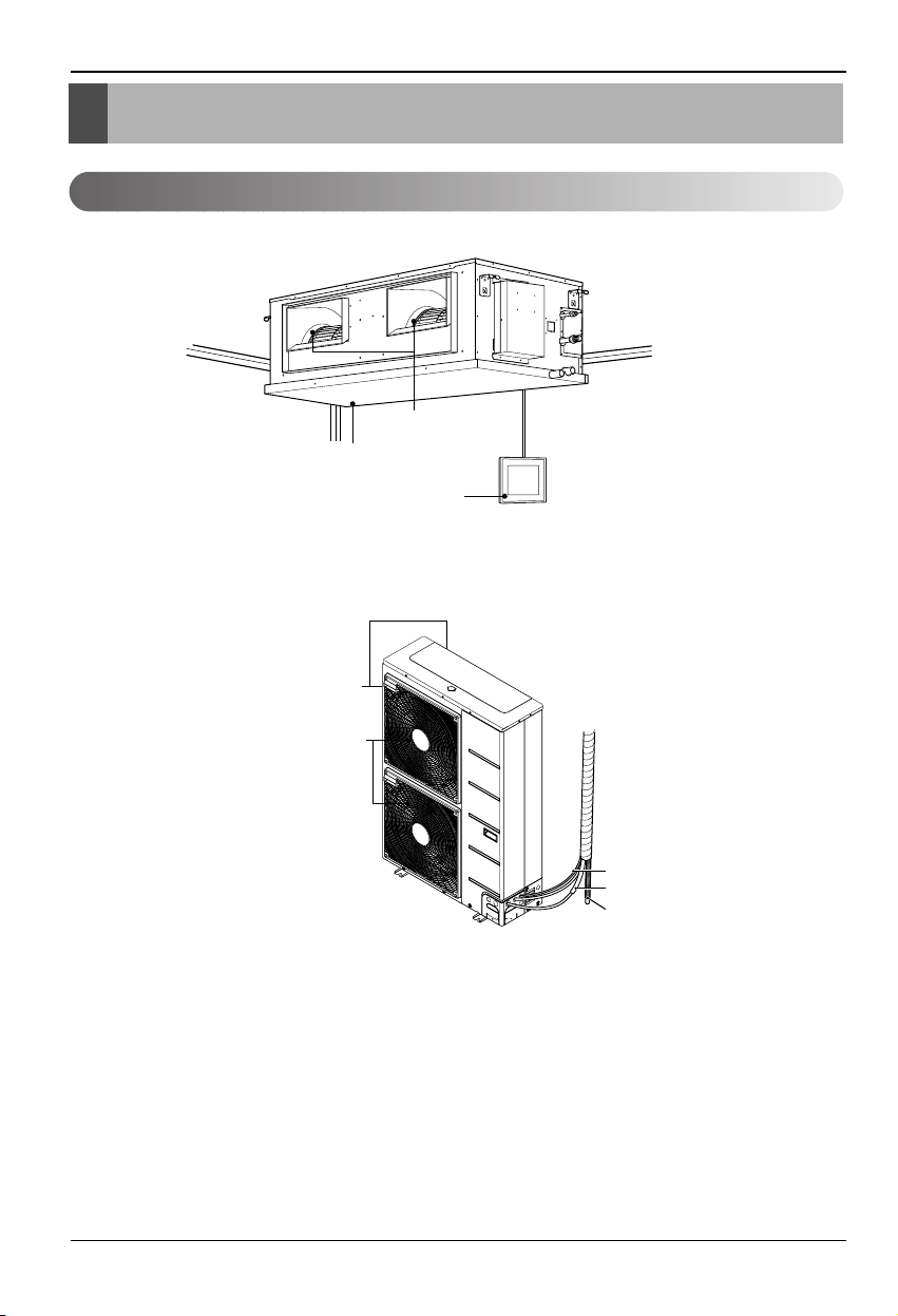
Installation Parts Provided
Remote Controller
Air intake vents
Air outlet vents
rain hose
over
Connection pipe
Drain hose
Connecting wire
Air outlet
vents
(Side)
(Rear)
Air intake
vents
Introduction
Features
Installation Manual 7
Installation of Indoor, Outdoor Unit
Installation of Indoor, Outdoor Unit
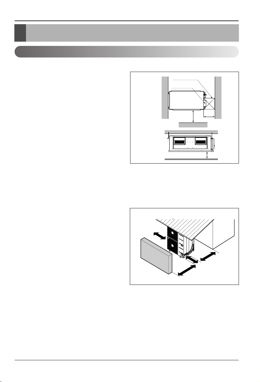
Indoor unit
Install the air conditioner in the location that
satisfies the following conditions.
• The place shall easily bear a load exceeding
four times the indoor unit’s weight.
• The place shall be able to inspect the unit as
the figure.
• The place where the unit shall be leveled.
• The place shall allow easy water
drainage.(Suitable dimension “H” is necessary
to get a slope to drain as figure.)
• The place shall easily connect with the outdoor
unit.
• The place where the unit is not affected by an
electrical noise.
• The place where air circulation in the room will
be good .
• There should not be any heat source or steam
near the unit
Outdoor unit
• If an awning is built over the unit to prevent
direct sunlight or rain exposure, be careful that
heat radiation from the condenser is not
restricted.
• There should not be any animals or plants
which could be affected by hot air discharged.
• Ensure the spaces indicated by arrows from
the wall, ceiling, fence or other obstacles.
Selection of the best location
H
450
Top view
(unit: mm)
Front view
Front
Inspection hole
(450 x 450)
Control box
1000
(Unit : mm)
More than
300
Fence or
obstacles
Sunroof
More than
100
More than
600
More than
700
8 Ceiling Concealed Duct Air Conditioner
Installation of Indoor, Outdoor Unit
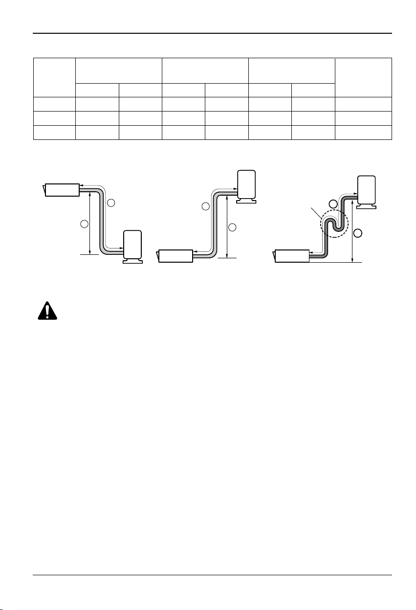
Piping length and the elevation
Outdoor unit
Indoor unit
A
B
Outdoor unit
Indoor unit
A
B
A
Oil trap
Outdoor unit
Indoor unit
B
If the elevation is more than 5 m
between indoor and outdoor.
CAUTION:
• The Standard pipe length is 7.5 m and no need to additional charge of
the refrigerant to max 15 m. If the pipe length exceeds 15 m, need to
additional charge of the refrigerant which according to the table.
• If 55 kBtu/h Model is installed at a distance of 50m, 2,100g of refrigerant
should be added (50-15) x 60g = 2,100g
• Capacity is based on standard length and maximun allowance length is on
the basis of reliability.
• Improper refrigerant charge may result in abnormal cycle.
• Oil trap should be installed every 5~7 meters.
Gas Liquid Standard Max. Standard Max
.
42 k 15.88(5/8) 9.52(3/8) 7.5 50 5 30 60
48 k 15.88(5/8) 9.52(3/8) 7.5 50 5 30 60
55 k 15.88(5/8) 9.52(3/8) 7.5 50 5 30 60
Capacity
Pipe Size
Length A(m) Elevation B(m)
*Additional
mm(inch)
refrigerant(g/m)
(Btu/h)
Installation Manual 9
Installation of Indoor, Outdoor Unit
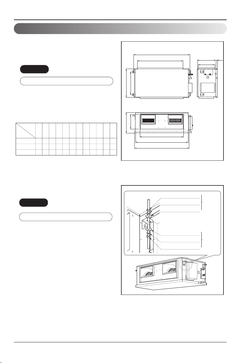
Indoor unit installation
■ Installation of Unit
Install the unit above the ceiling correctly.
CASE 1
POSITION OF SUSPENSION BOLT
• Apply a joint-canvas between the unit and
duct to absorb unnecessary vibration.
• Apply a filter Accessory at air return hole.
(Unit:mm)
Dimension
Capacity
(Btu/h)
ABCDEFGH I J KL
42 k
1362 1320 840 287 400 441 582 882 1373 315 366 40
48 k
1362 1320 840 287 400 441 582 1182 1373 315 366 40
55 k
1362 1320 840 287 400 441 582 1182 1373 315 366 40
CASE 2
POSITION OF SUSPENSION BOLT
I
H
FDEG
C
B
A
M10 Nut
M10 SP. washer
M10 washer
X 4
X 4
X 4
KL
J
(Local
supply)
• A place where the unit will be leveled and
that can support the weight of the unit.
• A place where the unit can withstand its
vibration.
• A place where service can be easily
med.
perfor
M10 washer
M10 SP. washer
M10 Nut
X 4
X 4
X 4
(Local
supply)
10 Ceiling Concealed Duct Air Conditioner
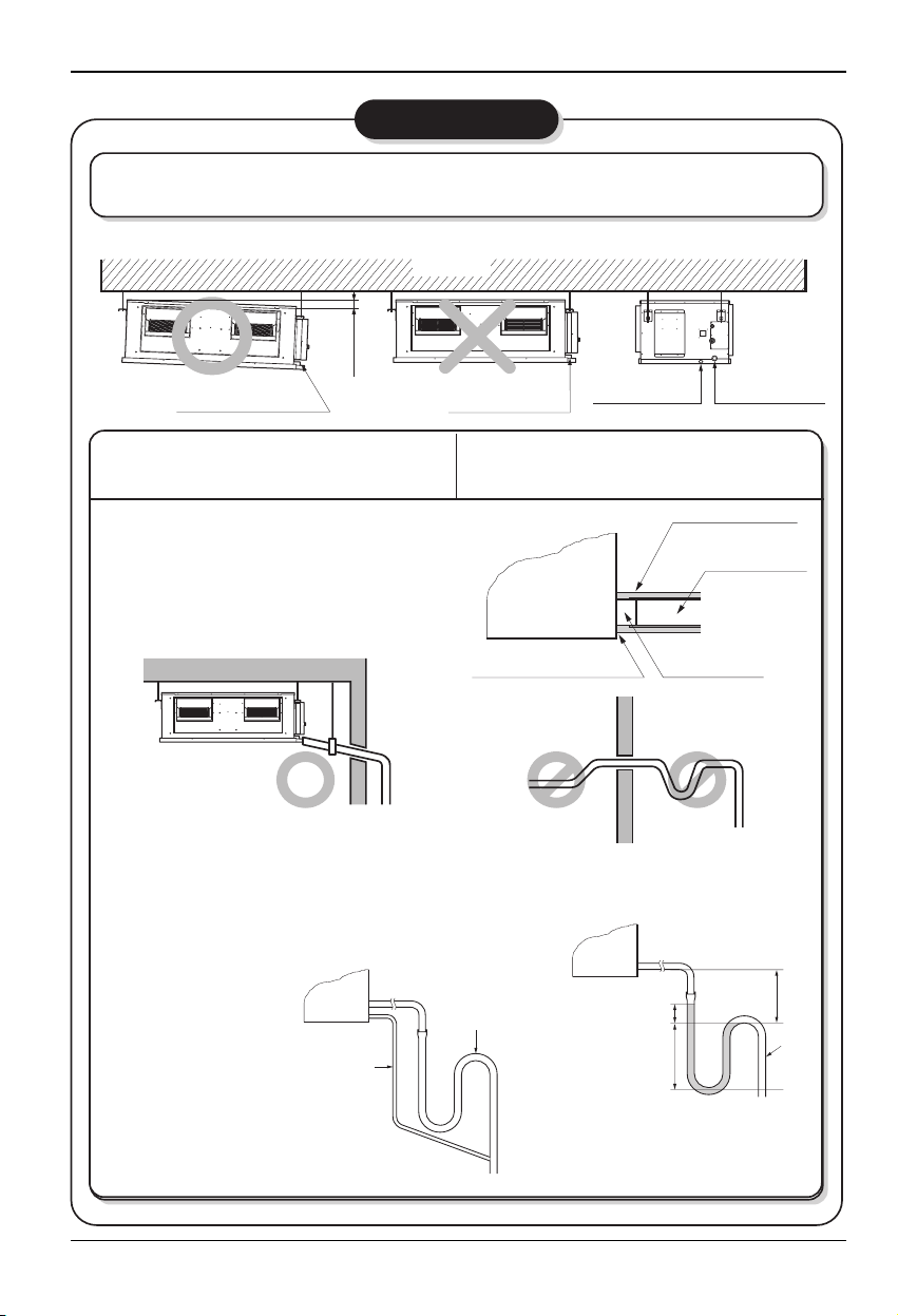
Installation of Indoor, Outdoor Unit
1. Main drain
• Always lay the drain with downward inclination
(1/50 to 1/100).
Prevent any upward flow or reverse flow in any part.
• 10mm or thicker formed thermal insulator shall
always be provided for the drain pipe.
2. Safety drain
• There is no need to
provide a trap for the
safty drain. If the
safty drain pipe is
connected to the
main drain pipe,
make the connection
below the trap on the
main drain pipe.
1. Install declination of the indoor unit is very important for the drain of the duct type air conditioner.
2. Minimum thickness of the insulation for the connecting pipe shall be 10mm.
• The unit must be declined to the drain hose connected when finished installation.
CORRECT
• Install the P-Trap (or U-Trap) to prevent
a water leakage caused by the blocking
of intake air filter.
CORRECT
INCORRECT
Applied U-Trap Dimension
INCORRECT
• Upward routing not
allowed
CAUTION
Ceiling
Drainage hole
1~3mm
CAUTION FOR GRADIENT OF
UNIT AND DRAIN PIPING
Safety drain pipe
Main drain pipe
Drainage hole
Lay the drain hose with a downward
inclination so water will drain out.
Safety drain hole Main drain hole
Unit
Make sure to be closed.
C
A ≥ 70mm
B ≥ 2C
C ≥ 2 x SP
SP = External
Pressure
(mmAq)
Ex) External Pressure = 10mmAq
A ≥ 70mm
B ≥ 40mm
C ≥ 20mm
A
Thermal insulator
(Local supply)
Drainage pipe
(Local supply)
Drainage hole
B
U-Trap
Installation Manual 11
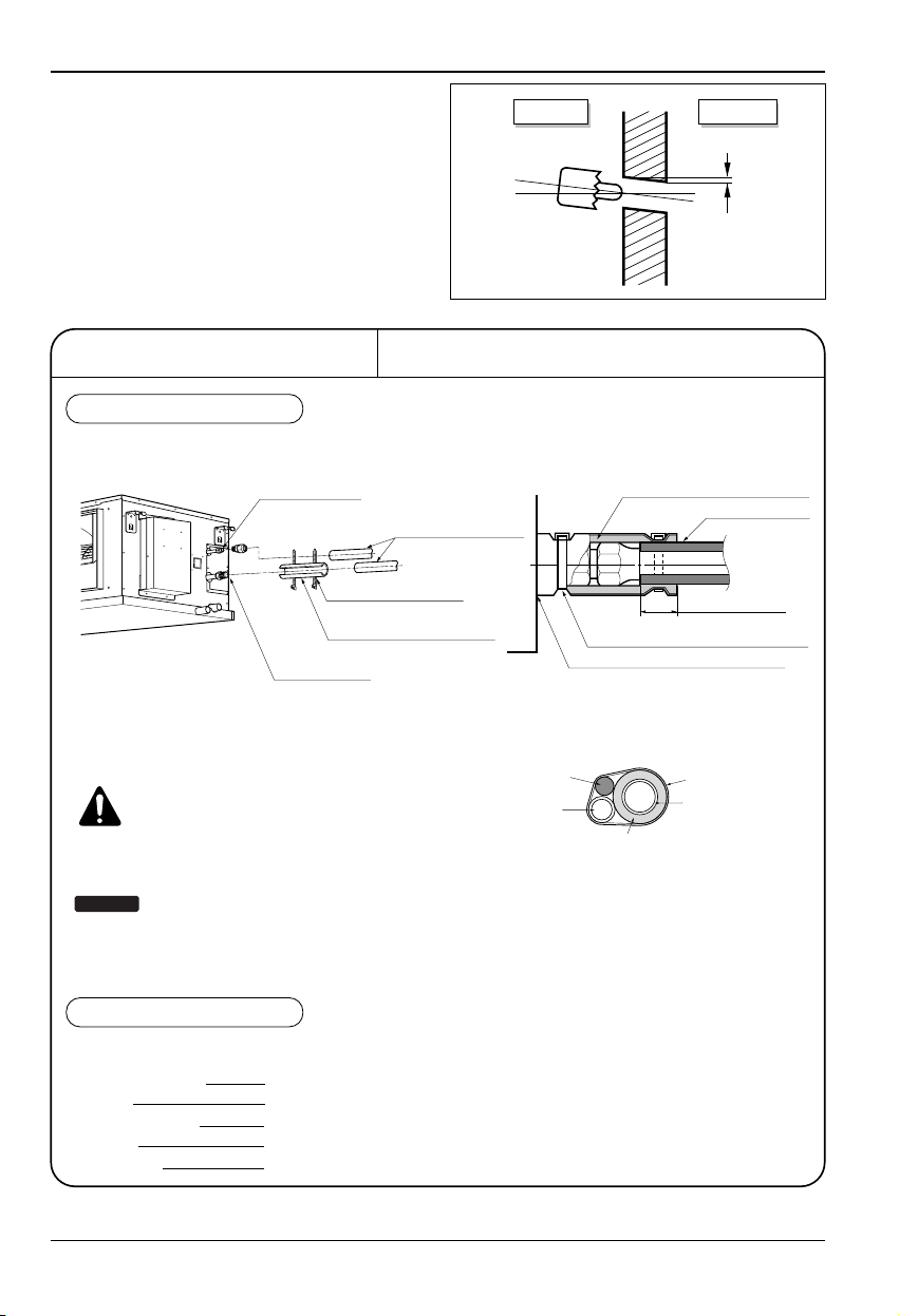
Installation of Indoor, Outdoor Unit
• Drill the piping hole with 70mm dia, hole core
drill.
• Piping hole should be slightly slant to the
outdoor side.
5~7mm
Indoor Outdoor
WALL
INSULATION, OTHERS
Insulate the joint and tubes completely.
All thermal insulation must comply with local requirement.
INDOOR UNIT
■ After all workings are finished, check the working and operation.
• Air distribution Is the air circulation good?
• Drain Is the drainage smoothly and no sweating?
• Gas leakage Is the piping connection correctly?
• Wiring Is the wiring connection correctly?
• Lock-bolt Is the lock-bolt of compressor loosened?
THERMAL INSULATION
TEST AND CHECK
Make sure that there is no clearance here.
Overlap with thermal
insulator for piping.
Thermal insulator for refrigerant pipe
(Local supply)
Thermal insulator for
piping(Local supply)
Hose crip for thermal insulator(Local supply)
Union for liquid pipe
Refrigerant pipe and thermal
insulator(Local supply)
Union for gas pipe
Thermal insulator for refrigerant pipe
(Local supply)
Hose crip for thermal insulator
(Local supply)
Power cable
Thermal insulator
Gas pipe
Liquid pipe
Tape
CAUTION: Cutting line of
insulation must look upper
direction. Thickness of
insulation is 10mm or over.
Recommended Insulation material
Meterial : FOAM PE
Thickness : 10mm
Density : less than 0.032 ±0.005(g/cm2)
Thermal conductivity : less than
0.03(kcal/m.hr.°C)
NOTICE
REFRIGERANT PIPE
• Insulate and tape the gas piping.
 Loading...