


INSTALLATION MANUAL
AIR
CONDITIONER
www.lg.com
Please read this installation manual completely before installing the product.
Installation work must be performed in accordance with the national wiring standards
by authorized personnel only.
Please retain this installation manual for future reference after reading it thoroughly.
Single Outdoor
ENGLISH
ภาษาไทย
*MFL68500221*
P/NO : MFL68500221
Copyright © 2018 LG Electronics Inc. All Rights Reserved.

2
TIPS FOR SAVING ENERGY
• Do not cool excessively indoors. This may be harmful to your health and may consume more electricity.
• Block sunlight with blinds or curtains while you are operating the air conditioner.
• Keep doors or windows closed tightly while you are operating the air conditioner.
• Adjust the direction of the air flow vertically or horizontally to circulate indoor air.
• Speed up the fan to cool or warm indoor air quickly, in a short period of time.
• Open windows regularly for ventilation as the indoor air quality may deteriorate if the air conditioner is used for many hours.
• Clean the air filter once every 2 weeks. Dust and impurities collected in the air filter may block the
air flow or weaken the cooling / dehumidifying functions.
For your records
Staple your receipt to this page in case you need it to prove the date of purchase or for warranty
purposes. Write the model number and the serial number here:
Model number :
Serial number :
You can find them labeled on the side of each unit.
Dealer’s name :
Date of purchase :
Here are some tips that will help you minimize the power consumption when you use the air
conditioner. You can use your air conditioner more efficiently by referring to the instructions
below:
TIPS FOR SAVING ENERGY
ENGLISH

IMPORTANT SAFETY INSTRUCTIONS
ENGLISH
IMPORTANT SAFETY INSTRUCTIONS
3
READ ALL INSTRUCTIONS BEFORE USING THE APPLIANCE.
Always comply with the following precautions to avoid dangerous situations and ensure peak
performance of your product
WARNING
!
It can result in serious injury or death when the directions are ignored
CAUTION
!
It can result in minor injury or product damage when the directions are ignored
WARNING
!
• Install or repair by unqualified persons can result in hazards to you and others.
• Installation MUST comply with local building codes. If there is no local codes, comply with
the Nation Electrical Code NFPA 70/ANSI C1-1003, Canadian Electrical Code Part1 CSA
C.22.1. or current edition.
• The information contained in the manual is intended for use by a qualified service technician
familiar with safety procedures and equipped with the proper tools and test instruments.
• Failure to carefully read and follow all instructions in this manual can result in equipment mal-
function, property damage, personal injury or death.
This appliance is not intended for use by persons (including children) with reduced physical, sen-
•
sory or mental capabilities, or lack of experience and knowledge, unless they have been given supervision or instruction concerning use of the appliance by a person responsible for their safety.
Installation
• Do not install duct through disassemble or repare the product yourself.
- This product can not install duct.
• Do not use a defective or underrated circuit breaker. Use this appliance on a dedicated circuit.
- There is risk of fire or electric shock.
• For electrical work, contact the dealer, seller, a qualified electrician, or an authorized service center.
- Do not disassemble or repair the product. There is risk of fire or electric shock.
• Always ground the product.
- There is risk of fire or electric shock.
• Install the panel and the cover of control box securely.
- There is risk of fire or electric shock.
• Always install a dedicated circuit and breaker.
- Improper wiring or installation may cause fire or electric shock.
• Use the correctly rated breaker or fuse.
- There is risk of fire or electric shock.
• Do not modify or extend the power cable.
- There is risk of fire or electric shock.
• Do not let the air conditioner run for a long time when the humidity is very high and a door or a win-
dow is left open.
- Moisture may condense and wet or damage furniture.
• Be cautious when unpacking and installing the product.
- Sharp edges could cause injury. Be especially careful of the case edges and the fins on the condenser and evaporator.
• For installation, always contact the dealer or an authorized service center.
- There is risk of fire, electric shock, explosion, or injury.
ENGLISH

4
IMPORTANT SAFETY INSTRUCTIONS
• Do not install the product on a defective installation stand.
- It may cause injury, accident, or damage to the product.
• Be sure the installation area does not deteriorate with age.
- If the base collapses, the air conditioner could fall with it, causing property damage, product failure,
and personal injury.
• Use a vacuum pump or Inert (nitrogen) gas when doing leakage test or air purge. Do not compress
air or Oxygen and do not use Flammable gases. Otherwise, it may cause fire or explosion.
- There is the risk of death, injury, fire or explosion.
• Do not turn on the breaker or power under condition that front panel, cabinet, top cover, control box
cover are removed or opened. Otherwise, it may cause fire, electric shock, explosion or death.
Operation
• Take care to ensure that power cable could not be pulled out or damaged during operation.
There is risk of fire or electric shock.
• Do not place anything on the power cable. There is risk of fire or electric shock.
• Do not touch(operate) the product with wet hands. There is risk of fire or electrical shock.
• Do not place a heater or other appliances near the power cable. There is risk of fire and electric shock.
• Do not allow water to run into electric parts. There is risk of fire, failure of the product, or electric shock.
• Do not store or use flammable gas or combustibles near the product. There is risk of fire or
failure of product.
• Do not use the product in a tightly closed space for a long time. Oxygen deficiency could
occur.
• When flammable gas leaks, turn off the gas and open a window for ventilation before turn the
product on. Do not use the telephone or turn switches on or off. There is risk of explosion or
fire.
• If strange sound, smell or smoke comes from product, turn the breaker off or disconnect the
power supply cable. There is risk of electric shock or fire.
• Stop operation and close the window in storm or hurricane. If possible, remove the product
from the window before the hurricane arrives. There is risk of property damage, failure of
product or electric shock.
• Do not open the inlet grill of the product during operation.(Do not touch the electrostatic filter,
if the unit is so equipped.) There is risk of physical injury, electric shock, or product failure.
• When the product is soaked (flooded or submerged), contact an authorized service center.
There is risk of fire or electric shock.
• Be cautious that water could not enter the product. There is risk of fire, electric shock, or
product damage.
• Ventilate the product from time to time when operating it together with a stove, etc. There is
risk of fire or electric shock.
• Turn the main power off when cleaning or maintaining the product. There is risk of electric
shock.
• When the product is not be used for a long time or the product use first time after test running, turn on main power switch before 6hours ago.
• Take care to ensure that nobody could step on or fall onto the outdoor unit. This could result
in personal injury and product damage.
ENGLISH

IMPORTANT SAFETY INSTRUCTIONS
ENGLISH
CAUTION
!
Installation
•
Always check for gas (refrigerant) leakage after installation or repair of product. Low refrigerant levels may cause failure of product.
•
Install the drain hose to ensure that water is drained away properly. A bad connection may cause
water leakage.
•
Keep level even when installing the product. To avoid vibration or water leakage.
•
Do not install the product where the noise or hot air from the outdoor unit could damage the neighborhoods. It may cause a problem for your neighbors.
•
Use two or more people to lift and transport the product. Avoid personal injury.
•
Do not install the product where it will be exposed to sea wind (salt spray) directly. It may cause corrosion on the product. Corrosion, particularly on the condenser and evaporator fins, could cause
product malfunction or inefficient operation.
Operation
•
Do not expose the skin directly to cool air for long periods of time. (Don't sit in the draft.) This could
harm to your health.
•
Do not use the product for special purposes such as preserving foods, works of art, etc. It is a consumer air conditioner, not a precision refrigeration system. There is risk of damage or loss of property.
•
Do not block the inlet or outlet of air flow. It may cause product failure.
•
Use a soft cloth to clean. Do not use harsh detergents, solvents, etc. There is risk of fire, electric
shock, or damage to the plastic parts of the product.
•
Do not touch the metal parts of the product when removing the air filter. They are very sharp! There
is risk of personal injury.
•
Do not step on or put anyting on the product. (outdoor units) There is risk of personal injury and failure of product.
•
Always insert the filter securely. Clean the filter every two weeks or more often if necessary. A dirty
filter reduces the efficiency of the air conditioner and could cause product malfunction or damage.
•
Do not insert hands or other objects through the air inlet or outlet while the product is operated.
There are sharp and moving parts that could cause personal injury.
•
Do not drink the water drained from the product. It is not sanitary and could cause serious health issues.
•
Use a firm stool or ladder when cleaning or maintaining the product. Be careful and avoid personal
injury.
•
Replace the all batteries in the remote control with new ones of the same type. Do not mix old and
new batteries or different types of batteries. There is risk of fire or explosion
•
Do not recharge or disassemble the batteries. Do not dispose of batteries in a fire. They may burn or
explode.
•
If the liquid from the batteries gets onto your skin or clothes, wash it well with clean water. Do not
use the remote if the batteries have leaked. The chemicals in batteries could cause burns or other
health hazards.
• If you eat the liquid from the batteries, brush your teeth and see doctor. Do not use the remote if
the batteries have leaked. The chemicals in batteries could cause burns or other health hazards.
5
ENGLISH

6
TABLE OF CONTENTS
2 TIPS FOR SAVING ENERGY
3 IMPORTANT SAFETY INSTRUCTIONS
7 INSTALLATION OF OUTDOOR UNIT
9 WIRING CONNECTION
9 Electrical Wiring
10 Connecting Cables between Indoor Unit and Outdoor Unit
12 Connecting the cable to Outdoor Unit
13 CONNECTING PIPES
13 Preparation of Piping
14 Connection of piping - Outdoor
15 Forming the piping
16 LEAKAGE TEST AND EVACUATION
16 Preparation
16 Leakage test
17 Evacuation
18 TEST RUNNING
20 INSTALLATION GUID AT THE SEASIDE
20 SEASONAL WIND AND CAUTIONS IN WINTER
TABLE OF CONTENTS
ENGLISH

INSTALLATION OF OUTDOOR UNIT
ENGLISH
INSTALLATION OF OUTDOOR UNIT
7
You need to select adequate installation location considering the following conditions, and make
sure to acquire the consent of the user.
Installation Places
- If an awning is built over the unit to prevent direct sunlight or rain exposure, make sure that
heat radiation from the condenser is not restricted.
- Ensure that the spaces indicated by arrows around front, back and side of the unit are respected.
- Do not place animals and plants in the path of the warm air.
- Take the air conditioner weight into account and select a place where noise and vibration are
minimum.
- Select a place so that the warm air and noise from the air conditioner do not disturb neighbors.
- Select a place that can sufficiently endure the weight and vibration of the outdoor unit and
where even installation is possible.
- Select a place that has no direct impact of snow or rain
- Select a place with no danger of snowfall or icicle drop
- Select a place without weak floor or base such as decrepit part of the building or with a lot of
snow accumulation
- Install at a place with fluent water draining to prevent damage from localized heavy rain and
avoid frequent flooded area.
Sunroof
More than
300mm
Fence or
obstacles
More than
More than
300mm
300mm
More than 600mm
More than 700mm

8
INSTALLATION OF OUTDOOR UNIT
Outdoor unit
Indoor unit
A
B
Outdoor unit
Indoor unit
A
B
Piping length and the elevation
MODEL
Pipe Size
mm(inch)
Length A
m
Elevation B
m
Additional-
Refrigerant
g/m
7.5 70 40AVUW60LM2A1
If installed tube is shorter than 7.5 m, additional charging is not necessary.
Additional Refrigerant = (A - 7.5 m) x Additional refrigerant (g)
CAUTION
!
ENGLISH
Ø 15.88(5/8)
Gas Liquid Standard Max. Max.
Ø 9.52(3/8)
30

WIRING CONNECTION
ENGLISH
WIRING CONNECTION
9
Electrical Wiring
Perform the electrical wiring work according
to the electrical wiring connection.
- All wiring must comply with local requirements.
- Select a power source that is capable of supplying the current required by the air conditioner.
- Use a recognized ELCB(Earth Leakage Circuit Breaker) between the power source and
the unit. A disconnection device to adequately disconnect all supply lines must be
fitted.
- Model of circuit breaker recommended by
authorized personnel only
Model Phase ELCB
AVUW60LM2A1 3 20 A
Main
power source
Indoor
ELCB
Switch box
Outdoor
ENGLISH
10
WIRING CONNECTION
Connecting Cables between Indoor Unit and Outdoor Unit
- Connect the wires to the terminals on the control board individually according to the outdoor
unit connection.
ENGLISH
- Ensure that the color of the wires of outdoor unit and the terminal No. are the same as those of
indoor unit respectively
R S T N 1(L) 2(N) 3
TO INDOOR UNIT
CAUTION
!
POWER SUPPLY
The power cord connected to the outdoor unit should be complied withIEC 60245 or HD 22.4
S4 (This equipment shall be provided with a cord set complying with the national regulation.
Area(mm
2.5(12AWG)
2
)
20mm
Model
AVUW60LM2A1
Phase (Ø)
3
The connecting cable connected to the outdoor unit should be complied with IEC 60245 or
HD 22.4 S4 (This equipment shall be provided with a cord set complying with the national
regulation.)
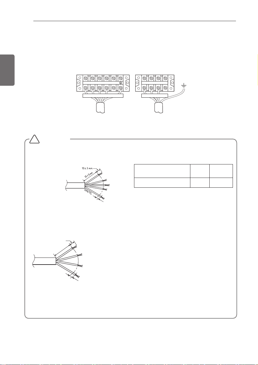
10(13/32) ± 3(1/8) mm(inch)
35(1-3/8) ±
5(3/16) mm(inch)
GN/YL
NORMAL
CROSS-SECTIONAL
AREA 0.75mm
2
When the connection line between the indoor unit and outdooor unit is over
40 m(131.2 ft), connect the telecommunication line and power line separately.
20(25/32) mm(inch)
If the supply cord is damaged, it must be replaced by a special cord or assembly available
from the manufacturer of its service agent.

Round pressure terminal
Power wire
Precautions when laying power wiring
ENGLISH
WIRING CONNECTION
11
Use round pressure terminals for connections to the power terminal block.
When none are available, follow the instructions below.
- Do not connect wiring of different thicknesses to the power terminal block. (Slack in the power
wiring may cause abnormal heat.)
- When connecting wiring which is the same thickness, do as shown in the figure below.
- For wiring, use the designated power wire and connect firmly, then secure to prevent outside
pressure being exerted on the terminal block.
- Use an appropriate screwdriver for tightening the terinal screws. A screwdriver with a small
head will strip the head and make proper tighterning impossible.
- Over-tightening the terminal screws may break them.

12
WIRING CONNECTION
Connecting the cable to Outdoor Unit
R emove the side panel for wiring connec tion. U s e the cord c lamp to fix the cord.
Earthing work
ENGLISH
- Case 1 : Terminal block of Outdoor Unit have mark.
Connect the cable of diameter 1,6mm
control box and do earthing.
- Case 2 : Terminal block of Outdoor Unit don't have mark.
Connect the cable of diameter 1,6mm
and fasten with earth screw
2
or more to the earthing terminal provided in the
2
or more, to the panel of control box, marked as
Connecting cable terminal
wer cord terminal
Cord clamp
* Make sure the rubber bushes are
connecting main power.
CAUTION
!
• The circuit diagram is not subject to change without notice.
• Be sure to connect wires according to the wiring diagram.
• Connect the wires firmly, so that They won’t be pulled out easily.
• Connect the wires according to color codes by referring the wiring diagram.
• The Power cord connected to the unit should be selected according to the specifications.

ENGLISH
CONNECTING PIPES
Preparation of Piping
Main cause of gas leakage is defect in flaring work.
Carry out correct flaring work in the following procedure.
Cut the pipes and the cable.
- Use the accessory piping kit or the pipes purchased locally.
- Measure the distance between the indoor
and the outdoor unit.
- Cut the pipes a little longer than measured
distance.
- Cut the cable 1.5 m(4.9 ft) longer than the
pipe length.
Copper
tube
CONNECTING PIPES
Slanted Uneven Rough
90°
13
ENGLISH
Burrs removal
- Completely remove all burrs from the cut
cross section of pipe/tube.
- Put the end of the copper tube/pipe to downward direction as you remove burrs in order
to avoid to let chips drop in the tubing.
Putting nut on
- Remove flare nuts attached to indoor and
outdoor units, than put them on pipe/tube
having completed burr removal.
(Not possible to put them on after flaring
work)
Flaring work
- Carry out flaring work using dedicated flaring
tool for R410A as shown below.
Outside diameter
A
mm inch mm inch
Ø 6.35 1/4 1.1~1.3 0.043~0.051
Ø 9.52 3/8 1.5~1.7 0.059~0.067
Ø 12.7 1/2 1.6~1.8 0.063~0.071
Ø 15.88 5/8 1.6~1.8 0.063~0.071
Ø 19.05 3/4 1.9~2.1 0.075~0.083
Firmly hold copper tube in a bar(or die) as indicated dimension in the table above.
Check
- Compare the flared work with figure below.
- If flare is noted to be defective, cut off the
flared section and do flaring work again.
Point down
Bar
Copper pipe
Smooth all round
Even length
all round
Pipe
Reamer
Flare nut
Copper tube
Bar
"A"
Clamp handle
Inside is shining without scratches
Inclined
Red arrow mark
= Improper flaring =
Surface
Cracked Uneven
damaged
Handle
Yoke
Cone
thickness

14
CONNECTING PIPES
Gas side piping
Liquid side piping
Connection of piping Outdoor
- Align the center of the piping and sufficiently
ENGLISH
tighten the flare nut by hand.
- Finally, tighten the flare nut with torque
wrench until the wrench clicks.
When tightening the flare nut with torque
wrench ensure the direction for tightening
follows the arrow on the wrench.
Outside diameter
mm inch N·m
Ø6.35 1/4 16±2
Ø9.52 3/8
Ø12.7 1/2
Ø15.88 5/8
Torque
wrench
Contin
-uous
- When connecting in a downward direction,
knock out the knock-out hole of the base
pan. (refer to figure 2)
<Figure 2>
Torque
Knock-out Base pan
38±4
55±6
75±7
Preventing foreign objects from entering
(Figure3)
- Plug the pipe through-holes with putty or
insulation material(procured locally)to stop up
all gaps,as shown in the figure 3.
<Figure 3>
* When tighten the pipe, hold the haxagonal
body.
Connecting wire
Drain hose
Connection pipe
Resin, Clay, Putty or insulating material
(produced locally)
CAUTION
!
Insects or small animals entering the out-
door unit may cause a short circuit in the
electrical box.

CONNECTING PIPES
15
Forming the piping
Form the piping by wrapping the connecting
portion of the indoor unit with insulation material and secure it with two kinds of vinyl tape.
- If you want to connect an additional drain
hose, the end of the drain outlet should be
routed above the ground. Secure the drain
hose appropriately.
In cases where the outdoor unit is installed
below the indoor unit perform the following.
1
Tape the piping, drain hose and connecting
cable from down to up.
2
Secure the tapped piping along the exterior
wall using saddle or equivalent.
Seal a small
Seal a small
o
opening around
pening around
the pipings with
t
he pipings with
gum type sealant.
um type sealer.
g
OU
OUTDOOR
T
D
U
UNIT
NI
Plastic
Plastic
band
band
O
O
R
T
Taping
Drain hose
Pipings
Connecting
cable
Power supply
cord
In cases where the Outdoor unit is installed
above the Indoor unit perform the following.
1
Tape the piping and connecting cable from
down to up.
2
Secure the taped piping along the exterior
wall. Form a trap to prevent water entering
the room.
3
Fix the piping onto the wall by saddle or
equivalent.
Seal a small opening
Seal a small opening
around the pipings
around the pipings
with gum type sealer.
with gum type sealant.
TrapTrap
OUTDOOR
OUTDOOR
UNIT
UNIT
Trap
ENGLISH
ENGLISH
• Trap is required to prevent water from entering
into electrical parts.

16
LEAKAGE TEST AND EVACUATION
LEAKAGE TEST AND EVACUATION
Air and moisture remaining in the refrigerant
system have undesirable effects as indicated
ENGLISH
below.
- Pressure in the system rises.
- Operating current rises.
- Cooling(or heating) efficiency drops.
- Moisture in the refrigerant circuit may freeze
and block capillary tubing.
- Water may lead to corrosion of parts in the
refrigeration system.
Therefore, the indoor/outdoor unit and connecting tube must be checked for leak tight,
and vacuumed to remove incondensible gas
and moisture in the system.
Preparation
Check that each tube(both liquid and gas side
tubes) between the indoor and outdoor units
have been properly connected and all wiring
for the test run has been completed. Remove
the service valve caps from both the gas and
the liquid side on the outdoor unit. Check that
both the liquid and the gas side service valves
on the outdoor unit are kept closed at this
stage.
CAUTION
!
To avoid nitrogen entering the refrigerant
system in a liquid state, the top of the
cylinder must be higher than its bottom
when you pressurize the system. Usually,
the cylinder is used in a vertical standing
position.
- Do a leakage test of all joints of the
tubing(both Indoor unit and outdoor unit) and
both gas and liquid side service valves.
Bubbles indicate a leak. Be sure to wipe off
the soap with a clean cloth.
- After the system is found to be free of leaks,
relieve the nitrogen pressure by loosening
the charge hose connector at the nitrogen
cylinder. When the system pressure is
reduced to normal, disconnect the hose from
the cylinder.
Indoor unit
Outdoor unit
Leakage test
Connect the manifold valve(with pressure
gauges) and dry nitrogen gas cylinder to this
service port with charge hoses.
CAUTION
!
Be sure to use a manifold valve for leakage
test. If it is not available, use a stop valve for
this purpose. The "Hi" knob of the manifold
valve must always be kept close.
- Pressurize the system to no more than
3,0 MPa with dry nitrogen gas and close
the cylinder valve when the gauge reading reached 3,0 MPa. Next test for leaks
with liquid soap.
Manifold valve
Lo Hi
Charge hose
Pressure
gauge
Nitrogen gas
cylinder(in vertical
standing position)

LEAKAGE TEST AND EVACUATION
ENGLISH
17
Evacuation
- Connect the charge hose end described in
the preceding steps to the vacuum pump to
evacuate the tubing and indoor unit.
Confirm the "Lo and Hi" knob of the manifold
valve is open. Then, run the vacuum pump.
The operation time for evacuation varies with
tubing length and capacity of the pump. The
following table shows the time required for
evacuation.
Required time for evacuation when 30 gal/h
If tubing length is
less than10 m (33 ft)
- When the desired vacuum is reached, close
the "Lo and Hi" knob of the manifold valve
and stop the vacuum pump.
Finishing the job
- With a service valve wrench, turn the valve
stem of liquid side valve counter-clockwise to
fully open the valve.
- Turn the valve stem of gas side valve counter-
clockwise to fully open the valve.
- Loosen the charge hose connected to the gas
side service port slightly to release the pressure,
then remove the hose.
- Replace the flare nut and its bonnet on the gas
side service port and fasten the flare nut securely with an adjustable wrench. This process is
very important to prevent leakage from the system.
- Replace the valve caps at both gas and liquid
side service valves and fasten them tightly.
This completes air purging with a vacuum pump.
The air conditioner is now ready to test run.
vacuum pump is used
If tubing length is
longer than 10 m (33 ft)
30 min. or more 60 min. or more
0.67 kPa or less
Indoor unit
Outdoor unit
Manifold valve
Lo Hi
Open
Vacuum pump
Open
Pressure
gauge
ENGLISH

18
TEST RUNNING
- The initial power supply must provide at least 90% of the rated voltage.
Otherwise, the air conditioner should not be operated.
- The test run is started by pressing the room temperature checking button and down timer but-
ton for 3 seconds at the same time.
- To cancel the test run, press any button.
CHECK THE FOLLOW ING ITEMS WHEN INSTALLATION IS COM PLETE
- After completing work, be sure to measure and record trial run properties, and store measured
data, etc.
- Measuring items are room temperature, outside temperature, suction temperature, blow out
temperature, wind velocity, wind volume, voltage, current, presence of abnormal vibration and
noise, operating pressure, piping temperature, compressive pressure.
- As to the structure and appearance, check following items.
- Connect the power supply cord to the independent power supply.
Circuit breaker is required.
- Operate the unit for fifteen minutes or more.
CAUTION
For test run, carry out the cooling operation firstly even during heating season. If heating operation
is carried out firstly, it leads to the trouble of compressor. Then attention must be paid.
Carry out the test run more than 5 minutes without fail.
(Test run will be cancelled 18 minutes later automatically)
!
Is the circulation of air adequate?
Is the draining smooth?
Is the heat insulation complete
(refrigerant and drain piping)?
Is there any leakage of refrigerant?
Is the remote controller switch operated?
Is there any faulty wiring?
Are not terminal screws loosened?
M4......118 N·cm / 12 kgf·cm / 87 klbf·in
M5......196 N·cm / 20 kgf·cm / 145 klbf·in
M6......245 N·cm / 25 kgf·cm / 181 klbf·in
M8......588 N·cm / 60 kgf·cm / 434 klbf·in
- Measure the temperature of the intake and discharge air.
-
Ensure the difference between the intake temperature and the discharge one is more than 8 °C.
Evaluation of the performance
Connection of power supply
Precautions In Test Running
TEST RUNNING
ENGLISH

TEST RUNNING
ENGLISH
CAUTION
!
After the confirmation of the above conditions, prepare the wiring as follows:
1
Never fail to have an individual power specialized for the air conditioner. As for the
method of wiring, be guided by the circuit diagram pasted on the inside of control box
cover.
2
Provide a circuit breaker switch between power source and the unit.
3
The screw which fasten the wiring in the casing of electrical fittings are liable to come
loose from vibrations to which the unit is subjected during the course of transportation.
Check them and make sure that they are all tightly fastened. (If they are loose, it could
give rise to burn-out of the wires.)
4
Specification of power source
5
Confirm that electrical capacity is sufficient.
6
Be sure that the starting voltage is maintained at more than 90 percent of the rated voltage marked on the name plate.
7
Confirm that the cable thickness is as specified in the power sources specification.
(Particularly note the relation between cable length and thickness.)
8
Never fail to equip a leakage breaker where it is wet or moist.
9
The following troubles would be caused by voltage drop-down.
- Vibration of a magnetic switch, damage on the contact point there of fuse breaking, disturbance to the normal function of a overload protection device.
- Proper starting power is not given to the compressor.
19
ENGLISH

20
INSTALLATION GUID AT THE SEASIDE
INSTALLATION GUIDE
AT THE SEASIDE
ENGLISH
CAUTION
!
• Air conditioners should not be installed
in areas where corrosive gases, such as
acid or alkaline gas, are produced.
• Do not install the product where it could
be exposed to sea wind (salty wind) di-
rectly. It can result corrosion on the
product. Corrosion, particularly on the
condenser and evaporator fins, could
cause product malfunction or inefficient
performance.
• If outdoor unit is installed close to the
seaside, it should avoid direct exposure
to the sea wind. Otherwise it needs additional anticorrosion treatment on the
heat exchanger.
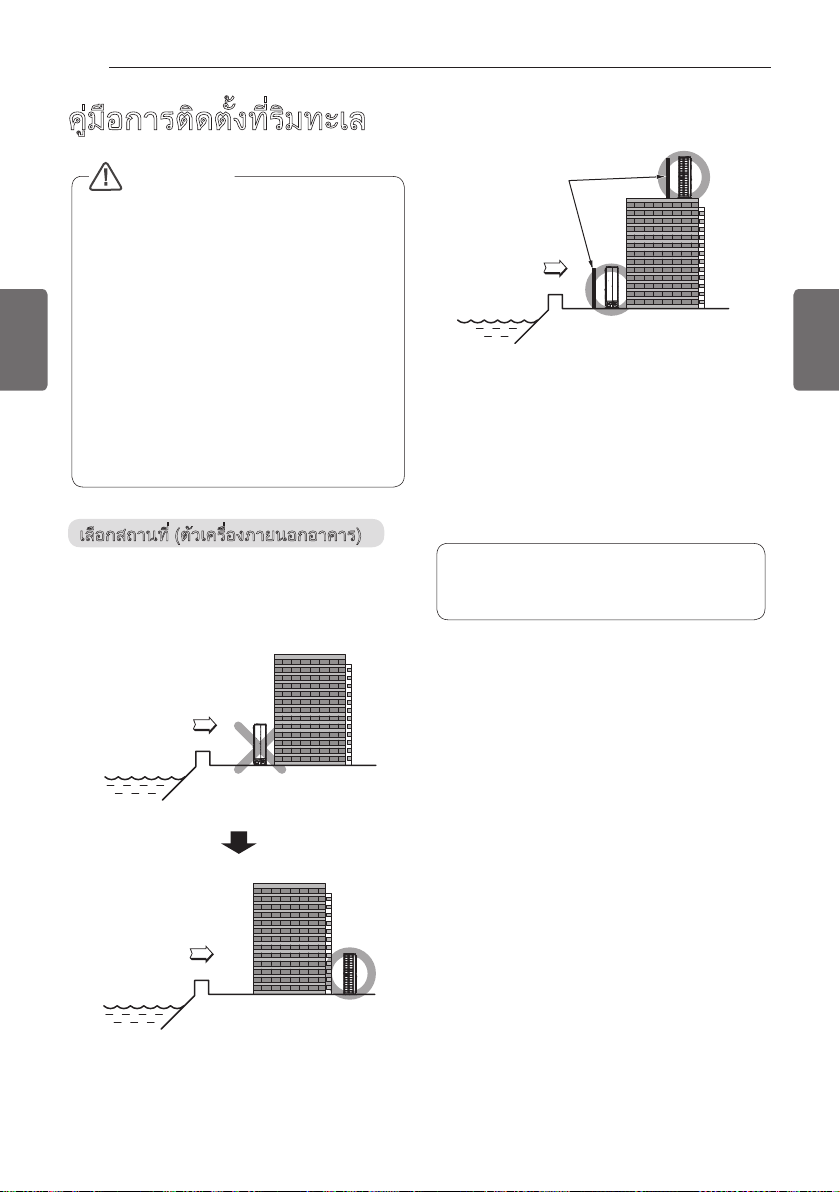
Selecting the location(Outdoor Unit)
If the outdoor unit is to be installed close to
the seaside, direct exposure to the sea wind
should be avoided. Install the outdoor unit on
the opposite side of the sea wind direction.
Sea wind
Sea wind
In case, to install the outdoor unit on the
seaside, set up a windbreak not to be
exposed to the sea wind.
Windbreak
Sea wind
- It should be strong enough like concrete to
prevent the sea wind from the sea.
- The height and width should be more than
150% of the outdoor unit.
- It should be keep more than 70 cm of space
between outdoor unit and the windbreak for
easy air flow.
Select a well-drained place.
• Periodic ( more than once/year ) clean-
ing of the dust or salt particles stuck on
the heat exchanger by using water
SEASONAL WIND AND
CAUTIONS IN WINTER
- Sufficient measures are required in a snow
area or severe cold area in winter so that
product can operate well.
- Get ready for seasonal wind or snow in winter even in other areas.
- Install a suction and discharge duct not to let
in snow or rain.
- Install the outdoor unit not to come in contact
with snow directly. If snow piles up and
freezes on the air suction hole, the system
may malfunction. If it is installed at snowy
area, attach the hood to the system.
- Install the outdoor unit at the higher installation console by 50cm than the average snow-
fall (annual average snowfall) if it is installed
at the area with much snowfall.
- Where snow accumulated on the upper part
of the Outdoor Unit by more than 10cm,
always remove snow for operation.


ภาษาไทย
ง้ัตดิตรากอืมู่ค
ศากาอบัรปงอ่ืรคเ
โปรดอ่านคู
และต
้
โปรดเก็บคู
ตง้ัตดิตราก
่
องเป
้
่
็
ยอง้ัตดิตรากอืม
่
ูผยดโง้ัตดิตงอ
ดไ่ีท
้
้
วไง้ัตดิตรากอืม
ชใอ่ืพเ
้
้อ้
*MFL68500221*
P/NO : MFL68500221
ณรูบมสดยีอเะลงา
์
ฟฟไยาสนิดเรากนาฐรตามมาตปไน
าของประเทศ
ทเตาญุนอบัร
น้ันา
่
้
กอนยาภบัรหำสนว่สกยแบบแศากาอบัรปงอ่ืรคเ
ดไกาจงัลหตคานอนใงิองา
านอย
้อ่
ฑณัภติลผง้ัตดิตน่อก
์
ลแดยีอเะลงา
่
ว
้
www.lg.com
Copyright © 2018 LG Electronics Inc. All Rights Reserved.

2
นางงัลพดัยหะรปรากบัรหาํสบัลด็ลคเ
็
เคล
็
นี่คือเคล
คุณสามารถใช้เครอ่ื บัรปง อากาศของคุณอย่าง ีมประสิทธิภาพได้มากขึ้นโดยอ้างอิงถึงคําแนะนําด้านล่าง:
• อย่าทําความเย็นจนภายในอาคาร ณุอีม ห ิมูภ เย็นจัด สิ่งนี้อาจจะเป็นอันตรายต่อส ภขุ าพของคุณและอาจใช
พล นางงั ไฟฟ้ามากขึ้น
ภาษาไทย
• ป้อ นักง แสงแดดด้วย ่ีทบังแสงหรือด้วยผ้าม่านในขณะ ่ีทคุณใช้งานเครอ่ื บัรปง อากาศอยู
• ให้ปิ ดประตูหรือหน้าต่างให้สน ใทิ นขณะ ่ีทคุณใช้งานเครอ่ื บัรปง อากาศอยู
• ปรับ ทศิท างของกระแสลมในแนวตั้งหร แอื นวนอน เพอ่ื หมุนเวียนอากาศภายในอาคาร
• เร่งความเร็ว ลดัพ มเพ ทอ่ืําให้ภายในอาคารเย็นหร ุออื่นขึ้นอย่างรวดเร็วในระยะเวลาสั้น
• ปรับตั้ง ภิมูภณุอ ายในห้อ บัรปง อากา 52 ่ีทศ ° C – 27° C เพอ่ื นางงัลพดัยหะรป
• ทําความสะอ น่ผแดา กรองอากาศทุกๆ 2 สัปดาห์ ฝุ่ นละอองและสิ่งสกปรก ่ีทสะสมอยู่ใ ศากาองอรกน่ผแน
อาจปิ ดกั้นกระแสลมหร ฟอื กงั์ช คยาบะรรากนั วามร้อน/ลดความชื้นให้เบาลง
ํ
สบัลด
าหร นางงัลพดัยหะรปรากบั
งาบบัลด อย่าง จ่ีท ะช่วยให้คุณลดการใช้พล เนางงั อ่ืม คุณใช้เครอ่ื บัรปง อากาศ
่
้
่
สํา นับรากบัรห ทึกของคุณ
เย็บใบเสร็จ งเบัร ินของคุณในหน้านี้ ในกร ่ีทีณ คุณจําเป็นต้องใช้ม พเนั ตอ่ื รวจสอบวัน อ้ืซ่ีท หรือสําหร รเบั อ่ื งการ
นักะรปบัร เขียนหมายเลขรุ่นและหมายเลขซีรีย์ที่น:่ี
หมายเลขรุ่น :
หมายเลขซีรีย์ :
คุณสามารถค้นหาได้ที่ป้ายกําก ดนบบั้านข้างของแต่ละเครอ่ื ง
อขอ่ืช งผู้จําหน่าย :
วัน : อ้ืซ่ีท

คําแนะนํ ส่ีทยัภดอลปมาวคา ํ ญัคา
3
คําแนะนํา ส่ีทยัภดอลปมาวค
อ่านคําแนะนํา กดมหง้ัท
ํ
คมาติตับิฏปาณุรก
ฑณัภติลผ
คํา นอืตเ
ข
้
คํา นอืตเ
การต ซอืรหง้ัตดิ
●
● การต ตะจง้ัตดิ
ถ้าไม
่
● ข้อม ูคนใลู
● หากไม่อ่านโดยละเอ มไะลแดยี
ณรกปุอ
●
● อย่าต ทง้ัตดิ่อผ
● อย่าใช้เบรคเกอร์วงจรทช่ีํา ปราการตัอีมอืรหดุร
● สํา ฟฟไบบะรนางบัรห
- อย่าแยกส่วนประกอบหร ซอื
●
ต
่
● ต านหน่นแ้หใมุคบวคงอ่ลกบอรคาฝะลแงผแง้ัตดิ
● ต รอกเครบเะลแรจงวง้ัตดิ
● ใช้เบรคเกอร์หร สวิฟอื
● อย่าปร อเพิ่มความยาวของสายไฟืรหนย่ีลปเบั
● อย่าปล่อยให้เคร ทศา
● ใช้ความระม นรากนใงัวะรดั
- ขอบแหลมคมอาจทําให
●
ส
ํา หใ ง้ัตดิตรากบัรห ้ ตดิต
ม -
าแนะนําต
สามารถทํางานด
์
ตยฉเกิพเกาห
อคําแนะนําอาจส่งผลให
่
งัวะรรวคอ
ตยฉเกิพเกาห
อคําแนะนําอาจส่งผลให
่
่
องสอดคล
้
ดนหำกอ้ขีม ท้องถ ใน่ิ ดนหำกอ้ขบักงอ้ลคดอสง้ัตดิตห
่
์
ง้ัตดิตราก
่
ฑณัภติลผ -
นี้ไม
่
์
ํ
ทะจ่ีทงย่ีสเมาวคีม -
าให
้
า ให้ตดิต
้
ํ
สนิดยาสอ
า ฑณัภติลผบัรห
ํ
าให
ทะจ่ีทงย่ีสเมาวคีม -
้
ํ
ทะจ่ีทงย่ีสเมาวคีม -
าให
้
์
ํ
ทะจ่ีทงย่ีสเมาวคีม -
าให
้
ํ
ทะจ่ีทงย่ีสเมาวคีม -
าให
้
รอซเนดเนอค
์
ํ
ทะจ่ีทงย่ีสเมาวคี
าให
้
่
้
้
เสมอ
เสมอ
์
กาอบัรปงอ่ื
ํ
า ฑณัภติลผาอเ
้
่
่
ตยาหยีสเมาวคดิกเ
่
์
้
่
ทง้ัตดิตถรามาส
อได
่
่
ํ
างานเป
ยหเะรงอ่ืรคเะลแ
ชใะจ่ีทนอ
้
ดุสงูสพาภิธทิสะรปยว
้
้
มไ่ีทลคคุบยดโมซแมอ
่
ดนหำกอ้ขบักงอ ทราคาอ
SC 1 ่ีทนว่สา้ฟฟไรากดนหำกอ้ข A นับุจจัปบับฉอืรห าดานคแงอข .1.22.C
คงสะรปุถตัวีม้ีนบับฉอืม
่
สน้ิชกยแดอถรากนา
่
มหไงิลพเดิกเ
มหไงิลพเดิกเ
มหไงิลพเดิกเ
มไ่ีทง้ัตดิตรากอืรหฟไยาสนิดเราก -
เหมาะสม อาจทําให
่
ปราการตัอีม่ีท
้
มหไงิลพเดิกเ
ม
หไงิลพเดิกเ
ํ
จนทแวัตอ
าหน
มหไงิลพเดิกเ
ชใรากอ่ืพเ
์
ํ
คมาติตับิฏป
าแนะนํา ูคนใดมหง้ัท
ยพัรทอ
์
ง้ชใรากบัรหำสะามหเ่มไ้ีนา้ฟฟไ้ชใงอ่ืรคเ ทาสะรปงาท พาภยากนา้ดงาทงอ่รพกบ่ีท)ก็ดเงึถมวร(ล
ซอืรหนว
่
้
้
ฟฟไอืรห
าช็อตได
้
้
ํ
จนทแวัตอ
าหน่าย ผู้ขาย ช่างไฟฟ
ฑณัภติลผมซแมอ
ม ทะจ่ีทงย่ีสเมาวคี ําให้ มหไงิลพเดิ
์
ฟฟไอืรห
าช็อตได
้
้
ฟฟไอืรห
าช็อตได
้
้
ตกูถนักงอ
อง
้
ฟฟไอืรห
าช็อตได
้
้
ฟฟไอืรห
าช็อตได
้
้
็
์
็
จเดาบรากดิกเ
บได
ให้ใช้ความระม ปเงัวะรดั ็
้
่
็
ไฟฟ้าช
้
ชใงอ่ืรคเ
ไฟฟ้า
้
็
จเดาบรากดิกเ
็
จเดาบรากดิกเ
บเล็กน
องถิ่น
้
งานโดยช
้
จเดาบรากดิกเ นิส
คคุบยดโนา
นกระแสไฟฟ้าต่ำกว่าที่กำหนด ใช้เครื่องใช้ไฟฟ้านี้ในวงจรไฟฟ้าที่กำหนดักงอ
้
้
้
้
้
้
ยนูศอืรหยา
์
ํ
า ญัค
่
็
บต
ณรากนาถสงย่ีลเกีลหอ่ืพเ อมสเ้ีนปไอ
์
ดไติวีชยีสเอืรหงรแนุรบ
้
็
ปเง้ัทกีอ ยารตนัอีม่ีท
นการทําให้แน่ใจว่า
ภาษาไทย
ฑณัภติลผอืรหยอ
้
่
่
ฑณัภติลผมซแมอ
ด
้
์
้
มหไงิลพเดิกเ
้
ฑณัภติลผง้ัตดิตรากะลแกออ
ดไ่ีทรากิรบ
้
ดไอืรห ดิบเะร ตอ
้
เสียหายได
์
ฟฟไราก
าสากล 3001-1C ISNA/07 APFN
้
่ี นางิตับิฏปรากนา้ดนใงอรบัรรากนา่ผทคินคทเงา
มสะามหเ่ีทบอสดทอืมงอ่ืรคเะลแ์ณรกปุอ้ชใรากะลแยัภดอลปมาวคอ่ืพเ
สะจ ้ีนบับฉอืม
ํ
ทอืรหลคคุบอ
าให
้
น้ันา่ลหเลคคุบงอขยัภดอลปมาวคบอชดิผบัร่ีทู้ผยดโ า้ฟฟไ้ชใงอ่ืรคเ้ชใ
งอเณุควัตยว
กเ ้ ฟฟไอืรห ้ าช็อตได้
ฟฟไอืรห
าช็อตได
้
้ดไยาหยีสเอืรหกยีปเ์รอจเิน์รอฟเ้หใำท ำ้นดยหน็ปเวัตน่ัลกจาอน้ืชมาวค -
์
อมสเตาญุนอบัร
็
จเดาบรากบัร
บได
้
งผลให
่
ตดิตอืรห ิตับมสณุคีม่ีทา
้
้
้
ดไติวีชยีสเ
้
ยนูศ่ีทอ
่
์
้ดไน่ือู้ผะลแณุควัตอ่ตง้ัทยารตนัอน็ปเ้หใลผง่สะจงรตยดโญาชวย่ีชเมาวคีม
นใิตกปดิผมาวคดิกเ
รากบักวย่ีกเำนะนแำคอืรหลแูดรากบัร้ดไ่ีทีณรกน้วเกย ู้รมาวคะลแ์ณรากบสะรปดาขอืรห จใติจงาทะลแสัผมัส
ดไ่ีทรากิรบ
นหอืรหูตะรปดิปเะลแกามงูสศากาอนใน้ืชมาวคอ่ืมเนานาลวเะยะรน
้าต่
ตาญุนอบัร
้
วไง้ิทงา
้
งอขบีรคะลแนาฐงอขบอขณวเิรบ่ีทษศเิพน

คําแนะนํ ส่ีทยัภดอลปมาวคา ํ ญัคา
4
ภาษาไทย
• อย่าต ช่ีทน้ืพนบงอ่ืรคเง้ัตดิ
- อาจทําให้ได
• ต้องแน่ใจว่าบร มไง้ัตดิต่ีทน้ืพณวเิ
- รคเ ดุรทนาฐกาห รจาอศากาอบัรปงอ่ื
• ใช้ป กอืรหศากาญญูสม๊ั
• อย่าเปิ ดเบรกเกอร
้
์
การทํางาน
• ให้ใช้ความระม หใอ่ืพเงัวะรดั
ทํางานอยู
• อย่าวางส ทะจ่ีทงย่ีสเมาวคีม ฟไยาสนบงล ๆดใงอขง่ิ
• อย่าส ท(ขณะ สัผมั
• อย่าวางเคร ทงอ่ืําความร
ฟ้าช็อตได
• อย่าให้น
• อย่าเก็บหร ชใอื้ก
• อย่าใช้ผล ฑณัภติ
• เม กอ่ื
• หากม ฑณัภติลผกาจาม ๆกลปแนัวคอืรห น่ิลก งยีสเี
• เม รอฮเุยาพอืรหมุสรมดิกเอ่ื
ก
• อย่าเปิ ดตะแกรงทางเข
• เม ฑณัภติลผอ่ื
• ระม ์ฑณัภติลผา้ขเำ้น้หใรวค่มไงัวะรดั
เสียหายได
• ระบายอากาศของเคร ปเงอ่ื
• ปิ ดแหล่งไฟฟ
• เม มไอ่ื่ใช
• ให้ใช้ความระม หใอ่ืพเงัวะรดั
่
ํ
า ฑณัภติลผ )นาง
้
ํ
าเข
้
้
ฟฟไ ดิกเอืรห
าช็อตได
้
๊
ำท์ฑณัภติลผ้หใ
์
๊
่
ยติถส
ชติวส
ูยอ่ีท
่
ฟฟไดิกเ
าช
้
ฑณัภติลผ
์
ฟฟไอืรห
าช็อตได
้
้
์
ชทิวสดิปดิปเอืรห
์
็
รอฮเุยาพ่ีทนอ
์
์
เปี ยกโชก (น
์
มหไงิลพเดิกเ
้
้
้
ฑณัภติลผ
ผกัลหฟไ
านไปก
่
้
ํ
า ดุร
็
จเดาบรากบัร
่
๊
ยอะลแ นจเิซกอออืรหนัด
าใช้ก
่
๊
็
จเดาบ ติวีชยีสเะจ่ีทงย่ีสเมาวคีม -
บ ไฟไหม
ขเฟไดิปเอืรห
้
ูยอดิปเอืรหกออดอถกูถมุคบวค
่
ใจว่าสายไฟฟ้าจะไม
้แน่
ํ
ทะจ่ีทงย่ีสเมาวคีม
าให
้
้
สน้ิชนใปไา
วนของไฟฟ้าได
่
้
้ดไดาลพดิผนาง
หใ ลหไว่ัรฟไวไซา
ปิดแก๊สและเปิดหน้าต
้
มหไงิลพเดิกเอืรหตอ
้ได้
์
ฟฟไดิกเอืรห
าช็อตได
้
้
้
ดไรากงอขงย่ีสเมาวคีม )
้
ํ
าท
้
่
็
อตได
ฟฟไอืรห
าช
้
้
็
ํ
ทอ่ืมเกัลหา
า บอืรหดาอะสมาวค
็
เป
์
ัช 6 นอ
่
ใจว่าไม
้แน่
ํ
ทจาอ้ีนง่ิส ราคาอกอนยาภ
าให
ํ
ทอืรห ุตหเิตับุอ บ
าให
วงหล่นทําให้ยพัรท
่
ชเิม ฟไวไซา
่
้
ดงผแกาหงอ่ืรคเา
มหไงิลพเดิกเ
้
์
ชใงอ่ืรคเอืรหนอ
้ฟ้
้
ลกใฟไดิตราสอืรหฟไวไซา
้
็
ปเบคแดิป่ีทน้ืพนใ
นเวลานาน อาจทําให
่
ํ
ทะจ่ีทงย่ีสเมาวคีม ฟไ
าให
้
หในคเิร
ชใดุยห้งานและปิดหน้าต่าง หากเป็นไปได้ ให้ย
้
ฑณัภติลผงอขา
งมโว่
้
ํ
ทะจ่ีทงย่ีสเมาวคีม งึถามะจนคเิร
าให้ยพัรท
ในขณะทํา รพมาวคีมงอ่ืรคเกาห( นาง
์
็
จเดาบบัร
บทางร
่
ํ
ูยอมจอืรหมว
น
า) ให้ตดิต
้
่ใต้
ชใอ่ืมเวารคง้ัรคน
งานร
้
ํ
า ฑณัภติลผาษกัรงุร
ชใอืรหนานาลวเน
้
่
จเดาบรากดิกเ
ฑณัภติลผ
้
าลวเมาตปไมอ่ืสเ
ทอ่ืมเ )นจเรตโนไ( ยอ่ืฉเซา
านหน้า กล
้
่
ฑณัภติลผ
็
บต
เสียหายได
์
์
ํ
า ลไอืรหว่ัรรากบอสดทราก
ํ
ทจาอน้ันน
าให
้
ดไดิบเะรอืรห
้
่
มหไฟไดิกเจาอ น้ันะฉิม
ไฟฟ้าช
้
่
ฟฟไอืรห
าช็อตได
้
ํ
าให
้
ลกใ ๆน่ือา
้
ํ
ทะจ่ีทงย่ีสเมาวคีม
าให
ฑณัภติลผบัก
์
้
ให้ปิดเบรคเกอร
์
์
ฟฟไดิกเ ยากงา
่
ํ
ทะจ่ีทงย่ีสเมาวคีม
าให
้
็
เป
์
กดใลคคุบีม
้
่
็
้
้
าช
้
ยนูศอ
์
ฯลฯ ฟไ าตเบักมว ทะจ่ีทงย่ีสเมาวคีม
์
้
มหไงิลพเดิกเ
้
ํ
ทอืรหามกอองึดกูถ
าให้เสียหายระหว
มหไงิลพเดิกเ
อืรห
้
ํ
ทะจ่ีทงย่ีสเมาวคีม กยีปเอืมตอน
าให
้
ทะจ่ีทงย่ีสเมาวคีม
ดไนจเิซกออดาข
้
กศากาอยาบะรอ่ืพเ งา
่
มหไงิลพเอืรหดิบเะรรากดิกเ
้ได้
์
็
ดไ่ีทรากิรบ
มหไงิลพเดิกเ
้
ดไ่ีทกาจงัลหกรแง้ัรคน
รอืรหนบนืยปไน้ึขวา
วงหล
่
ํ
ชงอ่ืรคเ ยาหยีสเนิส
า ดไลคคุบะลแดุร
อากาศ อย่าใช้งานก
่
อืรห
ดบอรคาฝ งอ่ืรคเวัตงอ
านบน ฝาครอบกล่อง
้
่
ฟฟไ
าช็อตได
้
มหไงิลพเดิกเ
้
ํ
าให
อม อย
้
้
้
้
มหไงิลพเดิกเ
้
ํ
ทะจ่ีทงย่ีสเมาวคีม ฟไยาสบัก
าให
้
้
ฑณัภติลผดิปเะจ่ีทนอ
อย่าใช้โทรศัพท์
์
้
ํ
ทรากดิกเ ยาหยีสเมาวคดิกเนิส
างานล้มเหลวของ
่
็
จเดาบรากดิกเอืรห ตอ
บต่ลคคุบอ
็
ฟฟไดิกเ
าช
้
ํ
าให
้
ํ
ทะจ่ีทงย่ีสเมาวคีม
าให
้
สงัยปไน
่
่
ตยาหยีสเมาวคดิกเะลแลคคุบอ
่
้
๊
ดไดิบเะรรากดิกเ
้
ดไติวีชยีสเอืรห ดิบเะรรากดิกเ ตอ
้
ฟฟไอืรห
าช็อตได
้
มหไงิลพเดิกเ
มหไงิลพเดิกเ
อาจทำอืรห
้
ฑณัภติลผยา
จากหน้าต่าง
์
อืรห ตอ ฑ์ณัภติลผ
ฟฟไดิกเ
าช็อตได
้
ลแงอ่ืรคเนิดเบอสดท
ว ให้เปิด
้
ฑณัภติลผอ
ได
้
์
็
จเดาบ บัร
บได้
งรแดัอซา
ํ
กงอ่ืรคเ่ีทงา
า งัล
้
ฟไอืรห
้
ดาลพดิผนางำท์ฑณัภติลผ
ํ
ทะจ่ีทงย่ีสเมาวคีม ฟไยาสดอถอืรห
าให
้
ฟฟไงอรกวัตสัผมัสา
า
้
ํ
ทะจ่ีทงย่ีสเมาวคีม ตาญุนอบัร
าให
้
มหไงิลพเดิกเ
้
้
สงอ่ืรคเวัตงอขนว
วน
่

คําแนะนํ ส่ีทยัภดอลปมาวคา ํ ญัคา
งัวะรรวคอ้ข
ง้ัตดิตราก
้
นงอขลหไว่ัรรากดิกเ
่
รกดักกูถ
อนได
่
ณุคงอขพาภขุส อ
็
่
็
บได
ํ
า ฑณัภติลผกาจ
้
็
ํ
าได
้
สน้ิชกยแอืรห
่
กจาอนัม นา
ทนใดใน่ือุถตัวอืรหอืมดอสา
้
็
ํ
าความเย็น) ของก
์เสียหายได้ฑณัภติลผ
ํ
า หใอ่ืพเ
้
้
อให
่
้
็
ยเศากาอบักสัผมัสงันหวิผ
นโดยตรงเป
คงสะรปุถตัวอ่ืพเ
้
่
ทอ่ืมเงรแง
้แน่
ฑณัภติลผง้ัตดิต่ีทะณขนใ
์
นวกบรงยีสเ่ีท่ีทนใ รศากาออืรห
้
รกดักราก
อน โดยเฉพาะอย
่
ชเ ษศเิพ
์
ฑณัภติลผงอขะหลโน
ฑณัภติลผนบงอขง่ิสงาวอืรหนบนืยา
์
ฑณัภติลผงอขวลหเม
ํ
ทรากนใพาภิธทิสะรปดละจกรปกส่ีทงอรก
า ทจาอะลแ ศากาอบัรปงอ่ืรคเงอขงอรกวัตงอขนาง
ฑณัภติลผอ
ได
้
์
ขเนัดมลอ
้
ไม
์
ํ
า บอืรห ดาอะสมาวค
ดเทภเะรปน
ใจว
ํ
างานไม
่
ขเกอฟกัซงผ
์
ได
์
๊
่
้
ตาหญัปดิกเ
บนอ่ืพเอ
านของคุณ
่
้
ยกยโอืรหกยรากนใน้ันา
้
่
็
นระยะเวลานาน (อย
้มข้
ฑณัภติลผงอข กิตสาพน
ได
์
ณรกปุอดุช(
้
่
ํ
ทะจ่ีทงย่ีสเมาวคีม ่ีรอตเตบแงอขนักงา
าให
ยอ ่ีรอตเตบแงอขนว
่
าไป ให
้
กจาอ่ีรอตเตบแนใีมคเราส ลหไว่ัรรากีม่ีรอตเตบแ
อให
่
ฑณัภติลผยา
่
กจาอ ศากาองอขลหไรากงอขกอออืรหา
้
์
ํ
า ฑณัภติลผาษกัรงุร
้
าของคุณ ให้ดกัซ้วยน
้
กจาอ่ีรอตเตบแนใีมคเราส ลหไว่ัรรากีม่ีรอตเตบแกาห
อให
่
้
้
้
ซอืรหง้ัตดิต่ีทกาจงัลห ซา
่
ํ
นยาบะรรากีมะจา
า ตมอ่ืชเราก งอ่ืรคเกาจปไกออ
้
สงอ่ืรคเกาจนอ
ูยอ่ีทน
ว่ภายนอกอาคารก่อให
่
็
จเดาบรากงย่ีลเกีลห
์
อให
่
มหไยอรดิกเ
สีม่ีทมล( ลเะทมล บักงรตยดโสัผมัสจาอ่ีทณวเิรบนใ
่
ดไพาภิธทิสะรปีม
้
่
้
ดไยาหยีสเมาวคบัร
์
ฑณัภติลผ่ีทะณขกอออืรหา
ทํางานอยู่สีม
์
กจาอะลแยัมานอขุสกูถ
อให
่
มหไงิลพเดิกเ
้
มหไยอรดิกเ
้
ปเอืรห
้
้
้
็
บต่ลคคุบอ
รอซเนดเนอคนใง่ิยงา
์
ํ
ทรากดิกเ
างานล
้
ํ
ท ะจ่ีทงย่ีสเมาวคีม ฯลฯ ยาละลวัต น
าให
ตงย่ีสเมาวคีม )ราคาอกอนง้ัตดิต่ีท
บอืรห ่อยกว
่
่
์
ยอ ลรทโนอคทมโีรนใดมหง้ัทนักวยี
่
ดไดิบเะรอืรห
้
ํ
ทจาอ ฟไงอกนใ่ีรอตเตบแง้ิทา
าให้ไหม
ํ
าสะอาดให้สะอาด อย่าใช้ทมโีร
้
็
ปเอืรห
ตยารตนัอน
่
ฑณัภติลผมซแมอ
ํ
นงอขลหไว่ัรรากอืรหนอืทเะสน่ัสรากงย่ีลเกีลหอ่ืพเ
า
้
้
อการบาดเจ็บต่ลคคุบอ
่
ตกาหน้ันา
้
ํ
าให
กเ่ีรอตเตบแนปา
าและใหม่อืรห
่
้
ตยารตนัอน
่
ยทพแบพปไะลแณุคงอขนัฟงรปแ
อย่าใช
์
ดพาภขุสอ
• ทราส( ลหไว่ัรรากบอสจวรตน่ัมห
ทําความเย็นต
• ทง้ัตดิต่อระบายน
ทําให
• มแบัดะราษกัร
• อย
่
เสียหายต
• ใช
้
• อย
่
ทําให
อาจทําให
้
้
ํ
า อาจทําให
่
้
่
ฑณัภติลผ
้
ํ
า นยาบะรอ่ืพเ
้
ฑณัภติลผง้ัตดิตา
์
บนอ่ืพเอ
้
วกกามอืรหนคงอสนค
ฑณัภติลผง้ัตดิตา
์
์
ฑณัภติลผ
ทํา ทอืรหดาลพดิผนาง
์
การทํางาน
• อย่าให
้
ตยารตนัอ
่
• อย่าใช
ระบบทำความเย็นที่ถูกต้องแม่นยำ มีความเสี่ยงที่จะทำให้เกิดความเสียหายหรือสูญหายต่อทรัพย์สินได้
• อย
่
• ใช้ผ้านุ่มทําความสะอาด อย่าใช
็
ฟ้าช
• อย
่
บาดเจ็บส
• อย
่
• ใส
่
• อย
่
ทําให
้
• อย่นม่ืดา
• ใช้ม
้
เจ็บต่ลคคุบอ
• ใส
่
• อย่าชาร์จใหม
• ผอ้ืสเอืรหงันหวิผนบสัผมัส่ีรอตเตบแกาจวลหเงอขกาห
ได
้
กาห
• ขเ่ีรอตเตบแกาจวลหเงอขนาทะรปบัรณุค
ฑณัภติลผ
้
์
ทน้ักดิปา
่
สน้ิชอืรห ตอ
่
สน้ิช
สัผมัสา
่
่
ํ
าจากท่อระบายน
้
ดไลคคุบนว
ํ
ทรากดิกเะลแ
างาน ล
หใงอรกวัต
นหนาอยู่เสมอ ทํา หาดปัส 2 ๆกุทงอรกวัตดาอะสมาวค
้แน่
สเมาวคอืรห ิตกป
ดไลคคุบ
้
มหในัอ่ีรอตเตบแ
และให้เป
่
ตกตแ่ีทดินช
่
่
ขเนัดมลอ
้
ปเ่ีทนว
็
ปเ่ีทนว
้
้
ตยาหยี
จเดาบบัร
ขแ่ีทดไนับอืรหง่ันา
5
ราสบัดะร
์
มไ่ีทอ
่
้
้
จาอีด
่
มาวคดิกเ
้
จาอ )อืลกเงออะลงอขบอกะรปนว
รมาวคยาบะรบีรคอืรห
อน
้
็
ปเจาอ้ีนง่ิส )มลสแะรกงาทศิทนใง่ันา
น
มไศากาอบัรปงอ่ืรคเอืค่ีน ฯลฯ ะปลิศนาง ราหาอาษกัรราก น
่ใช่
ฑณัภติลผงอขวลหเม
์
มหไงิลพเดิกเ
ไฟ
้
ตงย่ีสเมาวคีม !กามมคมาวคีม ศากาองอรกงอ่ืรคเดอถะณข
อการ
่
วัต รากงอ
้
ดไงรแนรุ่ีทพาภขุสาหญัปดิกเ
้
ดาบรากงย่ีลเกีลหะลแงัวะรดัมะร
ดไดิบเะรอืรห
้
ดพาภขุสอ
้
กาหทมโีร
ดไ ๆน่ือนา
้
ภาษาไทย
ดิผมาวคดิกเ
จาอง่ึซ่ีทนอ่ืลคเะลแมค่ีทนว
ๆน่ือนา

6
ญับราส
ญับราส
2 เคล
็
ํ
สบัลด
า ดพลังงานัยหะรปรากบัรห
3 ค
7 ณรกปุอดุช
ภาษาไทย
9 ตมอ่ืชเราก
9 ฟฟไยาสนิดเ
10 ตมอ่ืชเ
12 ตมอ่ืชเ
13 ตมอ่ืชเ
13 ทมยีรตเราก
14 ตมอ่ืชเราก
15 ทนิดเราก
16
16
16
17
18
20
ํ
าแนะนํา ่ีทสำคัญยัภดอลปมาวค
์
อสายไฟ
่
า
้
อสายไฟระหว
่
อสายไฟเข
่
่อท่
่อท่
อ
่
ทดสอบการทํางาน
่
้
อ
อ
่
อ - ภายนอกอาคาร
มยีรตเดัจราก
ลหไว่ัรรากบอสดทราก
ศากาญญูสำทราก
คู่มือการติดตั้งที่ริมละเล
สงอ่ืรคเงา
ูภายในอาคารและนอกอาคารยอ่ีทนว
่
่
ณรกปุอดุชบักา
ภายนอกอาคาร
์
การทำสูญญากาศะลแลหไว่ัรรากบอสดท
ราคาอกอนง้ัตดิต่ีท
20
ลมตามฤดูกาลและข้อควรระวังในฤดูหนาว

ราคาอกอนง้ัตดิต่ีท์ณรกปุอดุช
7
ณรกปุอดุช
์
คณควรเลือกตำแหน่งการติดตั้งที่เหมาะสม โดยพิจารณาจากเงื่อนไขและแน่ใจว่าได้รับความยินยอม
จากลูกค้า
ราคาอกอนง้ัตดิต่ีท
ง้ัตดิต่ีทนาถส
- นอ้รมาวคยาบะรงาทงาวข่มไงอ้ตะจดาสนัก นฝะลแดดแนักงอ้ปอ่ืพเ งอ่ืรคเวัตอืนหเู่ยอดาสนักีมกาห
ของคอนเดนเซอร
- ต้องแน่ใจว่าต
- นอ้รมลงอขยาบะรวนแมาต้วไ้มไน้ตอืรห์วตัสำน่มไ
- ให้คํา นงึถงึน
- นา้บนอ่ืพเนวกบร่มไะจศากาอบัรปงอ่ืรคเงอขงยีสเะลแนอ้รมลง่ึซง้ัตดิตณวเิรบก
อืลเ
- เลือกสถานที่ที่สารมารถรองรับน้ำหนักและการสั่นสะเทือนของตัวเครื่องภายนอกอาคารและสามารถทำการ
ติดตั้งได้
- เลือกสถานที่ที่ไม่ได้รับหิมะหรือฝนโดยตรง
- เลือกสถานที่ที่ไม่มีรอบรั่วของพื้น เช่น พื้นที่ก่อสร้างที่อ่อนตัวหรือมีหิมะปกคลุมจำนวนมาก
- ติดตั้งในสถานที่ที่สามารถระบายน้ำได้ดี เพื่อป้องกันความเสียหายจากฝนตกหนัก และหลีกเลี่ยงพื้นที่ที่เกิด
น้ำท่วมบ่อยครั้ง
ํ
า ดไนอืทเะสน่ัสมาวคะลแงยีสเดลถรามาส่ีทณวเิรบกอืลเะลแศากาอบัรปงอ่ืรคเงอขกันห
้
์
่ี
้
ข้างของตัวเครื่องนา้ดะลแ งัลหนา้ด า้นหนา้ด่ีท รศกูลยดโ้วไุบะร้ดไี่ทงัด ว่างทน้ืพีมงอ
้
า
Sunroof
More than
300mm
More than
More than
300mm
Fence or
obstacles
300mm
ภาษาไทย
ดุส่ีทีด
More than 600mm
More than 700mm

8
ความยาวท่อและค่าความสูง
ราคาอกอนง้ัตดิต่ีท์ณรกปุอดุช
AVUW60LM2A1
ภาษาไทย
รุ่น
ข
้
ทง้ัตดิตกาห
่
สารทําความเย
สงอ่ืรคเวัต
่
ขนาดท่อ
มม.(นิ้ว) เมตร
ก๊าซ ของเหลว มาตราฐาน สูงสุด ดุสงูส
Ø 15.88 (5/8) Ø 9.52 (3/8)
ความยาว A ค่าความสูง B
7.5 70 30 40
งัวะรรวคอ
วกน้ัสอ
่
็
ูยอ่ีทนว่ภายในอาคาร
B
5 เมตร ไม่จำเป็นต้องชาร์จเพิ่มเติม7. า
= มิตเม่ิพเน (A -7.5 เมตร) x สารทำความเย็นเพิ่มเติม (กรัม)
A
สงอ่ืรคเวัต
่
ภายนอกอาคาร
ูยอ่ีทนว
่
สงอ่ืรคเวัต
่
ภายในอาคาร
สาร
เมตร
สงอ่ืรคเวัต
่
ทําความ
็
เย
กรัม/เมตร
ูยอ่ีทนว่ภายนอกอาคาร
มิตเม่ิพเน
A
ูยอ่ีทนว
่
B

ตมอ่ืชเราก
อสายไฟ
่
ฟฟไยาสนิดเ
า
้
ฟฟไยาสนิดเ
าให้สอดคล
้
- ฟฟไยาสนิดเราก
ของประเทศ
- ลหแกอืลเ
ไฟฟ
- รอกเครบเ( BCLE ง้ัตดิต
ระหว่างแหล่งจ่ายกระแสไฟฟ
ต
้
กระแสจากสายไฟฟ้าเส้จ่ีทน่ายกระแสไฟฟ้าได
- ให
ของเบรคเกอร์วงจร
ายกระแสไฟฟ
่งจ่
้
ดไ่ีทลคคุบ
้
AVUW60LM2A1 3 20 แอมป์
้
ตดมหง้ัทา
้
ณรกปุอง้ัตดิตงอ
อีมํานาจหน้ทเ่ีทา
้
องเป็นไปตามข้อกําหนด
้
้
วงจรป
์
์
รุ่น เฟส ELCB
ํ
กศากาอบัรปงอ่ืรคเ่ีทมาตา
าหนดได
้
้
ฟฟไสแะรกดัต
้
่
ตมอ่ืชเรากบักงอ
อสายไฟฟ้า
่
จถรามาส่ีทา
ายกระแส
่
้
ฟฟไนักงอ
ปเน้ันา็นผู้แนะนํารุ่น
ฟไยาสอ่ตมอ่ืชเราก
9
แหล
่
กัลห
)ว่ัรา
้
งอ่ืรคเวัตบักา
ดัตถรามาส่ีทา
้
า้ฟฟไยา่จง
งอ่ืรคเวัต
ในอาคาร
ELCB
กล
่
นอกอาคาร
ชติวสงอ
ไฟ
์
งอ่ืรคเวัต
ภาษาไทย

10
ตมอ่ืชเ
อสายไฟระหว
่
- เชื่อมต่อสายไฟที่ขั้วต่อสายไฟบนชุดควบคุม เพื่อเชื่อมต่อตัวเครื่องส่วนที่อยู่ภายนอกอาคาร
- แน่ใจว่าสีสายไฟของตัวเครื่องส่วนที่อยู่ภายนอกอาคารและตัวเลขบนขั้วต่อสายไฟถูกต้องตาม
ตัวเครื่องส่วนที่อยู่ภายในอาคารตามลำดับ
ฟไยาสอ่ตมอ่ืชเราก
่
R S T N 1(L) 2(N) 3
สงอ่ืรคเงา
่
ูยอ่ีทนว
ภายในอาคารและนอกอาคาร
่
ภาษาไทย
แหล่งจ่ายไฟ
ตัวเครื่องส่วน
ที่อยู่ภายในอาคาร
ข
้
สายไฟฟ้าจากแหล่งจ่ายไฟที่ต่อเข้ากับเครื่องส่วนที่อยู่ภายนอกอาคารควรได้มาตรฐาน IEC 60245 หรือ
HD 22.4 S4 (เครื่องปรับอากาศต้องมีชุดสายไฟฟ้าที่ได้มาตรฐานตามข้อกำหนดในประเทศ)
สายไฟฟ้า ต่ีท่อไปที่ี่ตัวเครื่องส่วนที่อยู่ภายนอกอาคารควรได้มาตรฐาน IEC 60245 หรือ HD 22.4 S4
(เครื่องปรับอากาศต้องมีชุดสายไฟฟ้าที่ได้มาตรฐานตามข้อกำหนดในประเทศ)
ถ้าสายไฟฟ้าชํา ต ดุร
งัวะรรวคอ
10 ± 3 มม.
)ว้ิน( .มม )8/1( 3 ± )23/31( 01
)
)ว้ิน( .มม )61/3(
35 (1-3/8) ± 5
GN/YL
้
35 ± 5 มม.
20 มม.
)ว้ิน( .มม )23/52( 02
ดนย่ีลปเงอ
วยสายไฟฟ
้
รุ่น เฟส (Ø)
AVUW60LM2A1
ฟฟไยาสอ่ืมเ
ตมอ่ืชเา
นห่ีทน้ืพ
งอขดัตา
้
้
ภายในอาคารและภายนอกอาคารยาวกว่า
57.0 ิตกปฟไยาส
รตมเิลลิมงาราต
ทางไกลแยกออกจากสายไฟฟา
อระหว
้
่
หใ 40 ม.(131.2 ฟุต)
้ต่
่
อสายเส้ตดิตน
้
3
ูผงอขรากิรบนทแวัตยดโบอกะรปอืรห ษศเิพา
้
2.5(12AWG)
สงอ่ืรคเวัตงา
่
ราสอ่ืสอ
่
ติลผ
งาราต( ่ีทน้ืพ
)รตมเิลลิม
ูยอ่ีทนว
่

ฟไยาสอ่ตมอ่ืชเราก
11
ข
้
ใช
้
มไอ่ืมเ
ต่ีทง่ิสีม้องการ ให
่
- อย่าต่อสายไฟฟ้เส้นผ่านศูนย์กลางแตกต่างกันเข้ากับกล่องปลายขั้วีม่ีทา
(สายไฟฟ้หลวมอาจทำให้เกิดความร้อนมากผิดปกติ)่ีทา
- ตอ่ืมเ่อสายไฟฟ้ีเส้นผ่านศูนย์กลางเท่ากัน ให้ปฏิบัติดังแสดงในภาพด้านล่างม่ีทา
- สํา ฟฟไยาสนิดเรากบัรห
- ใช
้
- นนัขราก
ไม
่
นนัขถรามาส
็
อ่ืมเงัวะรรวคอ
เดินสายไฟ
ตมอ่ืชเอ่ืพเมลกงรทปูรนัดงรแว้ัขยาลป
อเข้ลกบักา
่
ทรงกลม
ํ
คมาติตับิฏป
นขั้วต่อสายไฟบงลดก่ีทกอนยาภนัดงรแ
็
นนัขอ่ืพเมสะามหเ่ีทงวคขไ
าแนะนํา ตงัด่อไปนี้
ํ
ทะจปไนิกเน
าใหขั้วต่อสายไฟแตกหรือชำรุดได้
้
้
า ให้ใช้สายไฟฟ้ก่ีทาําหนดและต่อสายไฟฟ้าให้แน
้
็
อตได
้
นแว้ัขยาลปตอ
่
่
ปูรนัดงรแว้ัขยาลป
หใว้ัขยาลปตอ
้แน่
วขั้วต่อสายไฟ้ัขยาลปงอ
สายไฟฟ้า
ภาษาไทย
่
็
ลเดานขีมวัหยาลป่ีทงวคขไ น
ก ส
หใดึยน้ันกาจ น
่
้แน่
ปอ่ืพเน
นักงอ
้
ํ
ทะลแ กออกีฉะจวัหนว
าให
้

12
ตมอ่ืชเ
อสายไฟเข
ถอดฝาด้านข้างเพื่อเชื่อต่อสายไฟ ใช้ที่ยึดสายไฟเพื่อยึดสายไฟฟ้าให้อยู่กับที่
การต
- กรณีที่ 1 : ขั้วต่อสายไฟของชุดอุปกรณ์ภายนอกอาคารมีสัญลักษณ์
- กรณีที่ 2 : ขั้วต่อสายไฟของชุดอุปกรณ์ภายนอกอาคารไม่มีสัญลักษณ์
ภาษาไทย
่
นิดยาสอ
่
ต่อสายไฟขนาด 1.6 ตร.มม. หรือมากกว่าที่ช่องสายดินบนขั้วต่อสายไฟบนชุดคอนโทรลเพื่อเชื่อม
สายดิน
ต่อสายไฟขนาด 1.6 ตร.มม. หรือมากกว่าที่บนแผ่นเหล็กของชุดคอนโทรลที่มีสัญลักษณ์
และขันให้แน่นด้วยสกรูสายดิน
ฟไยาสอ่ตมอ่ืชเราก
ณรกปุอดุชบักา
้
ภายนอกอาคาร
์
ตรวจดูให้แน่ใจว่าใส่บุชยาง
ที่รูสอดสายไฟอย่างถูกต้อง
หลังจากทำการต่อสายไฟฟ้าแล้ว
การเชื่อมต่อขั้วสายไฟ
ขั้วสายไฟ
ที่ยึดสายไฟ
!
•
จะไม่มีการแก้ไขแบบไดอะแกรมวงจรไฟฟ้าโดยไม่แจ้งให้ทราบ
•
ต้องแน่ใจว่าได้ต่อสายไฟฟ้าตามแบบไดอะแกรมวงจรไฟฟ้า
•
ต่อสายไฟฟ้าอย่างแน่นหนา เพื่อไม่ให้ถูกดึงออกมาได้ง่าย
•
ต่อสายไฟฟ้าตามรหัสสีตามแบบไดอะแกรมวงจรไฟฟ้า
•
ต้องเลือกสายไฟฟ้าที่ต่อเข้ากับตัวเครื่องตามข้อกำหนดเฉพาะ
งัวะรรวคอ้ข

ฟไยาสอ่ตอ่ืชเราก
13
นปลายท่อาบ
ที่ถูกต้อง
ตมอ่ืชเ
่อท่
ทมยีรตเราก
กงอขกัลหุตหเาส
๊
ใช้ตีธิว
อ
อ
่
ขอืคลหไว่ัรซา
อบกพร่องในการ
้
ํ
่
ทอ่ืพเ้ีนปไอ
นปลายท่อาบรากา
ทดัต่อและสายไฟ
- ปไว่ัท้ดไอ้ืซาห่ีทอ่ทอืรหอ่ท์ณรกปุอดุชชใ
้
- งอ่ืรคเวัตะลแนใยาภงอ่ืรคเวัตงา่วหะรงาทะยะรดัว
ภายนอกอาคาร
- ทดัต่อให้ยาวกว
่
็
ลเดัว่ีทงาทะยะรา
กน้อย
- )ตุฟ 9.4(รตมเ 5.1 อ่ทวายมาวคา่วกวาย้หใฟไยาสดัต
การกํา กออนย้ีสเดัจ
- กํา หใกออนย้ีสเดัจ
ท่อ
หมดจากหน
้
้
- ะณขนใ งา่ลนา้ดงลงดแงอทอ่ทงอขยาลปนา้ดำ่วค
กณุค่ีทํา มไงย่ีลเกีลหอ่ืพเ กออนย้ีสเดัจ
่ให้
เสี้ า้ขเนย
อ่ทนใปไ
ใส่น็อต
็
- นําน
ูยอดิต่ีทตอ
่
ูยอ่ีทงอ่ืรคเวัตบัก
ภายในและภายนอก
่
ว้ลแดมห
(ไม่สามารถใส่ได
้
ํ
ทกาจงัลห
อ่ทนาบราก
- A014R บัรหำส้วไดนหำก่ีทมาตะยะร้ชใยดโอ่ทนาบ
้ีนปไอ่ตงา่ลนา้ดงดสแ่ีทงัด
เส้นผ่ยนูศาน์กลางด้านนอก
A
มม. ว้ิน มม. ว้ิน
Ø 6.35 1/4 1.1~1.3 0.043~0.051
Ø 9.52 3/8 1.5~1.7 0.059~0.067
Ø 12.7 1/2 1.6~1.8 0.063~0.071
Ø 15.88 5/8 1.6~1.8 0.063~0.071
Ø 19.05 3/4 1.9~2.1 0.075~0.083
ทดึย่อทองแดงไว้ในแท
่
ํ
ก่ีทดานขมาตานห
าหนดไว้ในตารางด้านบน
ตรวจสอบ
- ทรากบยีทเบยีรปเ
ไปนี้
- ขีมกาห้อบกพร่องของท
บานออกและทําการบานท่อใหม่ง้ัรคกีอ
ํ
าให้ท
ดพาภบักนาบอ
่
่
านล่างต่อ
้
หใ กออนาบ่ีทอ
้
ท่อทองแดง
งยีอเ ไม่สม
ํ
าเสมอ ะรขุรข
่
ภาษาไทย
ท่อ
ูรนา้วค่ีท
งอขดัตยอรงอขดัตา
งล้ีช
็
น
ท่อทองแดง
กออนาบ่ีทตอ
กออนย้ีสเดัจำก่ีทอ่ทบัก่สใปไำนน้ันกาจ กออราคาอ
)ว้ลแอ่ทนาบรากา
นุมหมา้ด
บาร
์
ท่อทองแดง
น่นแ้หใ )บีบวัตอืรห( บัจง
สดัต
่
ความยาวเท่นักา
่ีทนว
อ่ทง้ัทบอร
นักอมสเบยีรเ
ด
้
บาร์
โน้งยีอเม แตกวิผน้ืพ
ดึย่ีทบัจมา
= บานออกไม่เหมาะสม =
เสียหาย
ดึยวัต
งดแีสรศกูลยามหงอ่ืรคเ
ขดีขยอรกาจศารปยดโมางางเนใยาภ
วน
่
ความหนา
ํ
ไม่สม
าเสมอ
่
ยวรกงรทปูร

14
อ่ทอ่ตมอ่ืชเ
การเชื่อมต่อท่อภายนอกอาคาร
- ยนูศง้ัต์ของท่อและใช้นนัขอืม
พอ
ภาษาไทย
- ทดุสนอตน้ัข
บานจนกว
ว
่
ประแจ
เส้นผ่ยนูศาน์กลางด้านนอก
Ø6.35 1/4 16±2
Ø 9.52 3/8 38±4
Ø 12.7 1/2 55±6
Ø 15.88 5/8 75±7
าย ให้ใช
้
่
ชใอ่ืมเ
้
มม. ว้ิน รตมเนัตวิน
้
็
ปเนัขรากงาทศิทา
ประแจวัดแรงบิด
ประกอบ
ท่อ
๊
ก๊ิลคงัดงยีสเีมะจา
็
นนัขดิบงรแดัวจแะรป
หในาบวัหตอ
ต นาบวัหตอ
องแน่ใจ
้
ดิบงรแ
งยีพเน
้แน่
็
นนัขดิบงรแดัวจแะรป
เมื่ีอเชื่อมต่อในทิศทางลง ให้เคาะที่จุดสำหรับใส่ท่อ
บริเวณฐานรองตัวเครื่องให้เกิดช่อง(อ้างอิงจากรูป
ภาพที่ 2)
วัหตอ
<รูปภาพที่ 2>
นบ้ีชรศกูลงอขงาทศิทมาตปไน
จุดเคาะช่อง
สำหรับใส่ท่อ
การป้องการสิ่งแปลกปลอมเข้าสู่ตัวเครื่อง
(รูปภาพที่ 3)
- อุดรูที่เป็นทางผ่านของท่อด้วยผงอุดรูหรือ
วัสดุที่เป็นฉนวน(ที่หาได้ทั่วไป) เพื่อปิด
ช่องว่าง ตามรูปภาพที่ 3
<รูปภาพที่ 3>
ฐานรองตัวเครื่อง
ท่อของเหลว
* มย่ีลหเกหน็ปเ่ีทนว่สงรตบัจ้หใ อ่ทนัขอ่ืมเ
ยาง,ดินเหนียว,ผงสำหรับอุดรู
หรือวัสดุที่เป็นฉนวน(ที่หาได้ทั่วไป)
ข้อควรระวัง
!
หากมีแมลงหรือสัตว์ชนิดเล็กๆเข้าไปในส่วนของ
ตัวเครื่องภายนอกอาคาร อาจทำให้ไฟฟ้าลัด
วงจรในส่วนของชุดควบคุมได้
ท่อก๊าซ
สายไฟเชื่อมต่อ
ท่อระบายน้ำทิ้ง
การเชื่อมต่อท่อ

ทนิดเราก
อ
่
นักยว้ด้วไา้ขเดิตดัม
- หากคุณต้องการต่อท่อระบายน
ปลายของท
ทดึย่อระบายน
สงอ่ืรคเวัต
่
ูยอรวคอ
่
่
ํ
าให้เหมาะสม
้
สงอ่ืรคเวัต่ีทีณรกนใ
่
ูยอ่ีทนว่ภายในอาคาร ให
ูยอ่ีทนว่ภายนอกอาคารอยู่ต
1 งา่ลกาจฟไยาสะลแำ้นยาบะรอ่ท ,อ่ทปที่ทเนัพ
นบน้ึข
2 ยว้ดกอนนา้ดงันผบักว้ลแปทเนัพ่ีทอ่ทดุชดึย
อ่ทดึยาข
้
ดุอุดสัวน็ปเ่ีทงายชใ
ดิปเงอ่ชดุอรากำท
อ่ทๆบอรก็ลเดานข
อ่ทอ่ตมอ่ืชเ
15
ในกรณีที่ติดตั้งตัวเครื่องส่วนที่อยู่ภายนอก
งอ่ืรคเวัตบักา้ขเดิตว้ลแนวนฉมุ้หยดโอ่ทนิดเ
อ่ืพเ ดินช 2 ลินวไปทเ้ชใะลแ ราคาอนใยาภ
อาคารอสูงกว่าตัวเครื่องส่วนที่อยู่ภายในอาคาร
ให้ปฏิบัติดังนี้
1 งา่ลกาจฟไยาสะลแำ้นยาบะรอ่ท ,อ่ทปที่ทเนัพ
ํ
า ด มิตเม่ิพเ
้
นิดน้ืพอืนหเ
ดัรยาส
้
ท่อระบายน
ท่อ
าน
้
ํ
ากว่า
่
้ีนงัดิตับิฏป
ปทเนัพราก
ํ
า
้
นิดเราก
ตมอ่ืชเ่อ
ลิบเคเยาส
นบน้ึข
2 กอนนา้ดงันผบักว้ลแปทเนัพ่ีทอ่ทดุชดึย
งอท่อเป็นจุดดักน้ำ เพื่อป้องกันน้ำไหลกลับเข้า
ห้องภายในอาคาร
ยึดท่อเข้ากับผนังด้วยขายึดท่อ3
Seal a small opening
ใช้ยางที่เป็นวัสดุอุด
around the pipings
ทำการอุดช่องเปิด
ขนาดเล็กรอบๆท่อ
with gum type sealer.
ข้องอดักน้ำ
Trap
OUTDOOR
OUTDOOR
UNIT
UNIT
ข้องอ
ดักน้ำ
ภาษาไทย
อาคาร
่ีทนว่สงอ่ืรคเวัต
อนยาภู่ยอ ก
า้ฟฟไ์ณรกปุอน็ปเ่ีทนว่ส
สายไฟ
ู่สา้ขเลหไำ้น้หใ่มไนักงอ้ปอ่ืพเำ้นกัดดุจำทงอ้ต

16
ยาบะรรากะลแลหไว่ัรรากบอสดท
ทดสอบการรั่วไหลและการทำสูญญากาศ
อากาศและความชื้นที่ตกค้างอยู่ภายในระบบ
สารทำความเย็นจะทำให้เกิดผลเสียดังนี้
- น้ึขม่ิพเบบะรงอขนัดงรแ
- น้ึขงูสฟไสแะรก
็
- ทรากพาภิธทิสะรป
ลดลง
ภาษาไทย
- ทราสวงจรนใน้ืชมาวค
ํ
- น
าอาจทําให้สน้ิช่วนของระบบทําความเย็นเป็น
้
สนิม ดังนั้น ต้องตรวจสอบส่วนของเครื่องที่ติดตั้ง
ภายในอาคาร/ภายนอกอาคาร และบริเวณจุดต่อ
ของท่อว่าไม่มีการรั่วไหลและไล่ด้วยสูญญากาศ
เพื่อกำจัดก๊าซที่ไม่ควบแน่น และความชื้นในระบบ
ํ
าความเย
ํ
าความเย็นอาจเป็นน
ทน้ักดิปะลแ
่
นัดงรแดลอ ของสารทำความเย็น
มยีรตเดัจราก
- ตรวจสอบว่าท่อแต่ละท่ทง้ัท( อ่อของเหลวและท
)ซาก
๊
อาคารได้ตมอ่ืชเ่ออย่างเหมาะสม และได
สายๆไฟฟ้าทั้งหมดสำหรับการทดสอบเดินเครื่อง
แล้วนำฝาปิดวาล์วออกจากท่อก๊าซและท่อของ
เหลวของตัวเครื่องส่วนที่อยู่ภายในอาคาร ตรวจ
สอบว่าวาล์วอยู่ในตำแหน่งปิดทั้งท่อของเหลว
และท่อก๊าซของตัวเครื่องส่วนที่อยู่ภายนอก
อาคาร
รมาวคอืรห( น ้อน)
้
ํ
าแข
้
ข
้
สารทำความเย็นในสถานะของเหลว เมื่อคุณปล่อย
ก๊าซไนโตรเจนเข้าระบบเพื่อเพิ่มแรงดัน ส่วนบน
ของถังก๊าซไนโตรเจนต้องอยู่สูงกว่าด้านล่างของ
็
ง
อ
่
กอนยาภะลแนใยาภู่ยอ่ีทงอ่ืรคเวัตงา่วหะร
ง้ัตดิต
ถัง โดยทั่วไป ใช้งานถังก๊าซในโตรเจนในตำแหน่ง
ตั้งตรง
- ทำการทดสอบการรั่วที่ข้อต่อของท่อทั้งหมด(ทั้ง
ตัวเครื่องส่วนที่อยู่ในอาคารและนอกอาคาร) และ
ทั้งท่อก๊าซและท่อของเหลวด้านวาล์ว ใช้ฟองสบู่
เพื่อตรวจรอยรั่ว และแน่ใจว่าเช็ดฟองสบู่ออก
ด้วยผ้าจนสะอาด
- หลังจากตรวจสอบเรียบร้อยและไม่พบรอยรั่ว ลด
แรงดันก๊าซไนโตรเจนโดยคลายท่อที่ติดกับถัง
ไนโตรเจน เมื่อความดันในระบบลดลงจนปกติ
ให้ถอดสายท่อออกจากถังไนโตรเจน
งัวะรรวคอ
มไงย่ีลเกีลหอ่ืพเ
าซไนโตรเจนเข้าไปในระบบ
่ให้ก๊
ตัวเครื่องส่วนที่อยู่ภายในอาคาร
ตัวเครื่องส่วนที่อยู่
ภายนแกอาคาร
ลหไว่ัรรากบอสดทราก
- ต่อสายเกจวัดแรงดันด้านหนึงเข้ากับถังก๊าซไนโตร-
เจนและอีกด้านหนึ่งกับท่อก๊าซ จากนั้นเปิดวาล์วเพื่อ
ป้อนไนโตรเจนเข้าท่อ
ข
้
ต้องแน่ใจว่าเกจวัดแรงดันไม่ชำรุด หากเกจวัด
แรงดันชำรุด สามารถต่อเกจวัดแรงดันเข้าทาง
ด้านวาล์วแรงดันสูงได้
- มไบบะรนัดมาวค
ด้วยก๊าซไนโตรเจนแห้งและปิดวาล์วป้อนน้ำยา
เมื่อมีการอ่านมาตราวัดถึง 3.8 MPa(551 psi)
ต่อไปให้ทดสอบการรั่วไหลด้วยน้ำสบู่
งัวะรรวคอ
วกนิกเ่า 3.8 MPa(551 psi)
่
เครื่องวัดความดัน
Lo Hi
เกจน์วัดความดัน
ท่อเติมไนโตรเจน
ถังไนโตรเจน
(ในตำแหน่งวางตั้ง)

ยาบะรรากะลแลหไว่ัรรากบอสดท
17
ศากาญญูสำทราก
-
ต่อปลายของสายเกจวัดแรงดันด้านหนึ่งเข้ากับท่อก๊าซ
และอีกด้านหนึ่งเข้ากับปั๊มสูญญากาศตามรูป ตรวจสอบ
ว่าวาล์วแรงดันต่ำ(Lo)และวาล์วแรงดันสูง(Hi)ของสาย
ของเกจวัดแรงดันอยู่ในตำแหน่งเปิด จากนั้นให้เปิด
ปั๊มสูญญากาศตามระยะเวลาในตารางด้านล้างนี้
ระยะเวลาการทำสูญญากาศเมื่อใช้ปั๊มสูญญากาศ ขนาด 30
ถ้าความยาวท่อน้อยกว่า
)ตุฟ 33( รตมเ 01
วกกามอืรห นาที 03
า วกกามอืรห นาที 06
่
0.67 kPa หรือมากกว่า
- เมื่อการทำสูญญากาศได้ค่าตามที่ต้องการ ให้ปิด
วาล์วแรงดันต่ำ(Lo)แล้ววาล์วแรงดันสูง(Hi)ของ
สายเกจวัด และปิดปั๊มสูญญากาศ
เมื่อทำสูญญากาศเสร็จ
- ใช
้
ของเหลวทวนเข
- ใช้ประแจหมุนวาล์วเพื่อหมุนก้านวาล์วด้านท่อก๊าซ
ทวนเข็มนาฬิกาเพื่อเปิดวาล์วให้สุด
- ค่อยๆถอดสายเกจวัดแรงดันออกจากท่อก๊าซ
- ยอ้รบยีรเ้หในอ่ืลเจแะรปยว้ดนัข ปไา้ขเบัลกาฝดิป
ออกจากระบบ
- ปิ ดฝาครอบวาล
น่นแ้หใ
ด้วยอากาศ
แล้ว
ลาวนุมหจแะรป
์
็
ํ
สมาวคีม้ีนนอตน้ัข
า ปอ่ืพเกามญัค
์
งมโว่ัช/นอลลกแ
ถ้าความยาวท่อมากกว่า
กนุมหอ่ืพเว
านวาล์วด้านท่อ
้
ลาวดิปเอ่ืพเากิฬานม
วให้ดุส
์
้
ลาวง้ัทว
์
ชใรากรากนวบะรกดุสน้ิส
้
รพศากาอบัรปงอ่ืรคเ้ีนะณข
้
มไนักงอ
่ให้ก๊
ลไอ่ืพเศากาญญูสม๊ัป
ทรากบอสดทะจ่ีทมอ
)ตุฟ 33( รตมเ 01
า
่
ระบบ
่
ํ
างาน
ว่ัรซา
นัขวลหเงอขะลแซา๊กอ่ทว
ตัวเครื่องส่วนที่อยู่ภายในอาคาร
ตัวเครื่องส่วนที่อยู่
ภายนอกอาคาร
เครื่องวัดความดัน
Lo Hi
เปิด เปิด
ปั๊มสูญญากาศ
เกจวัดแรงดัน
ภาษาไทย

ทดสอบการทํางาน
18
ทดสอบการทํางาน
ข
้
- ค
่
ชเิม
่
สํา หใบบะรนิดเรากบอสดทรากบัรห
ภาษาไทย
ทําให้คอมเพรสเซอร์เสียหายได
- ตม่ิรเ
้
- สามารถกดปุ่มใดๆ ก็ได
ตม่ิรเนางงัลพา
้นต้
ข
้
ตรวจสอบรายการต
- ทกาจงัลห
- ดไ บอสจวรต่ีทรากยาร
ออก ความเร
- สํา รสงรคโบัรห
มไอืรหอพงยีพเศากาอนยีวเนุมหราก
การระบายน
การหุ
(ท่อสารทําความเย็นและท่อระบายน
ทราสีมําความเย
ํ
างานเสร็ต น้ิสจ้องแน่ใจว่าได
ดไดัว้ เป็นต้น
็
ทงอขิมูภหณุอ
อและแรงดันก๊าซอัด
่
้
ํ
า มไอืรหน่ืรบาร
้
้
็
คีมงอ่าอย่างน้อย 90% ของค
มไะจจาอน้ันน
สามารถใช
่
้
งัวะรรวคอ
ดไบบะรนิดเบอสดท
นานกว
้
่
ุปดกยดโบบะรนิดเรากน
่
้
่
้แก่
?
่
รมาวคนักนวนฉม
ณรูบมสนอ
้
มไอืรหลหไว่ัรน
?
่
งอ่ืรคเนิดเงอลดทรากนใงัวะรรวคอ
ฟฟไนัดงรแ า
่
ดไศากาอบัรปงอ่ืรคเนาง
้
ทําความเย็นก่อนแม้ว่าจะเป็รูดฤน้อนก็ตาม ถ้าให้ทําความร้อนก่อนจะ
้
ต น้ันกาจ
้
องใช
้
้
มไบบะร่ีทยดโ ีทาน 5 า
หิมูภหณุอบอสดทม
องและปุ
้
บบะรบอสดทรากกิลเกยอ่ืพเ
้
หิมูภหณุอ
้
ฟฟไนัดงรแ มลรตามิรป มลว
า กระแสไฟฟ
้
หใ ภายนอกะณษกัละลแงา
ตรวจสอบ รายการต่อไปนี้
้
?
่
์
ํ
า มไอืรห )
้
?
่
่
้
M4......118 N•cm / 12 kgf•cm / 87 klbf•in
M5......196 N•cm / 20 kgf•cm / 145 klbf•in
M6......245 N•cm / 25 kgf•cm / 181 klbf•in
M8......588 N•cm / 60 kgf•cm / 434 klbf•in
ก่ีทาําหนด
้
งัวะรดัมะรมาวค
าหญัปีม
)ีทาน 81 น้ันกาจงัลห ิตัมนโตัอยดโกิลเกยะจบบะรนิดเบอสดทราก(
ดาลวเง้ัตม
็
็
รสเง้ัตดิตกาจงัลห้ีนปไอ
านล่าง พร
้
์
ณรูบมสจ
้
่
ชติวส
ฟฟไยาสนิดเรากีม
น
็
ปเนักมอ
้
์
ขเงึด่ีทศากาอิมูภหณุอ กอนยาภิมูภหณุอ งอ
้
ํ
ทลรทโนอคทมโีร
า มไอืรหนาง
มไอืรหมวลหว้ัขยาลปตอ
?
?
่
มไอืรหดาลพดิผา
?
่
่
กเดัจะลแบบะรนิดเบอสดทรากนใะณษกัลณุคกึทนับะลแดัว
็
บข้่ีทลูมอ
ชในัดงรแ ิตกปดิผ่ีทงยีสเะลแนอืทเะสน่ัสราก า
ีทานิว 3 าลวเน
งาน
้
ลป่ีทศากาอิมูภหณุอ ามา
อย
่
ตมอ่ืชเราก
อเข
่
- ต่อสายไฟฟ้าเข
- ปเงอ่ืรคเนิดเ
- ดงอขิมูภหณุอดัว
- ตรวจสอบให้แน่ใจว่าความแตกต่างระหว
็
ลหแบักา
้
้
ํ
ทรากลผนิมเะรป
างาน
านอากาศเข้าและปล่อยอากาศออก
้
ายกระแสไฟฟ้า
่งจ่
ลหแบักา
ายกระแสไฟฟ
่งจ่
ะรสิอบบแา
้
วกกามอืรห ีทาน 51 าลวเน
า
่
่
ต
้
ํ
นรากิมูภหณุองา
าเข้าและการปล
รอกเครบเีมงอ
วงจร
์
็
ปเง่ึนหยอ
นมากกว่า 8 องศาเซลเซียส
่

ทดสอบการทํางาน
19
ข
้
ดไกาจงัลห
1 ต
้
ไฟฟ
้
2 ชติวสง้ัตดิต
็
3 น
การขนส
ไฟฟ้าไหม้ได้)
4 ข
อกําหนดเฉพาะของแหล่งจ่ายกระแสไฟฟ้า
้
5 วนัยนืย
6 ต
7 วนัยนืย
8 ต
่
องแน่ใจว
้
่
กระแสไฟฟ้า (หมายเหตุพิเศษ ให้พิจารณาความสัมพันธ์ระหว่างความยาวกับเส้นผ่านศูนย์กลางของ
สายเคเบิ้ล)
องไม
้
่
9 ตาหญัป
- ชติวสงอขนอืทเะสน่ัสราก
- ไม่ได้กําหนดค
งัวะรรวคอ
ขพาภสนัยนืย
้
เบรคเกอร์วงจรระหว่างแหล่งจ่ายกระแสไฟฟ้าและตัวเครื่อง
์
่
่
เส้นผ่านศูนย์กลางของสายเคเบิ้ลสอดคล้องกับที่ระบุไว้ในข้อกำหนดเฉพาะของแหล่งจ่ายา
่
ณรกปุอ งอข
างต้นแล้ว ให
้
ลหแมยีรตเดัจงอ
ายไฟฟ้าเฉพาะให
่งจ่
ด่ีทรจงวงัผมาตา
านในของฝาปิดกล่องควบคุม
้
ฟฟไยาสนัข่ีทตอ
าในฐานของส
้
ฟฟไนัดงรแา
้
ฟฟไนัดงรแา
รอกเครบเง้ัตดิต
์
ป
้
์
่
่
็
นบอสจวรต งอ่ืรคเง
อพงยีพเา
ตม่ิรเา้นมากกว่า 90% ของค
้
แม่เหล็ก หน
์
ชใรากนักงอ
กระแสไฟฟ้นิกเา
้
้
้
ฟฟไง้ัตดิตนว
า อาจหลวมได
ลกงัดตอ
้
าวและต้องแน่ใจว่าได้หในัข้แน่น (หากน็อตหลวม อาจทําให้สาย
่
ฟฟไนัดงรแกาจามุตหเาสีมจาอ้ีนปไอ
าตก
้
้
ํ
สมสะามหเ่ีทนางงัลพา
า รอซเสรพเมอค บัรห
ฟฟไยาสนิดเรากมยีรตเดัจ
ส ศากาอบัรปงอ่ืรคเบัก
้
่
น้ืชมาวคีมอืรหกยีปเ่ีทณวเิรบนใรจงว
สวิฟงอขสัผมัสา
์
์
้
ํ
า ฟฟไยาสนิดเรากบัรห
ฟฟไนัดงรแา
้
้ีนงัดา
ก่ีทาําหนดไว้ในป
้
า ให
้
้
ํ
ทรากนวกบรราก ยาหยีสเรจงวดัต
างานปกติ
ยาสนิดเ
วหะร น้ึขดิกเจาอ่ีทนอืทเะสน่ัสมาวคกาจ
าง
่
ภาษาไทย
งอ่ืรคเนบยา
คู่มือการติดตั้งที่ริมทะเล
20
คู
ภาษาไทย
ถ
้
ต
้
ให
่
ข
้
• ต้องไม
่
ก๊ซที่มีฤทธิ์กัดกร่อน เช่น มีการผลิตก๊าซกรดา
หรือด่าง
• อย
่
รกดัก่อนได
ในคอนเดนเซอร
อาจทําให
ทํางานไม
• ถ
้
รกดัก
่
สงอ่ืรคเง้ัตดิต
่
ต่ีทีณรกนใ
้
ํ
กง่ิสง้ัตดิต
้
า มไอ่ืพเ มลงับ
้
่
ต ลเะทบัก
้
ชเิม โดยตรง
สงอ่ืรคเง้ัตดิตา
่
ลมทะเล
ลมทะเล
้
์
สงอ่ืรคเง้ัตดิตา
่
่
สกับลมทะเลโดยตรงัผมัสรากงย่ีลเกีลหงอ
ูยอ่ีทนว
่
ลเะทมลงอขงาทศิทบัก
งัวะรรวคอ
ฑณัภติลผง้ัตดิตา
์
สีม่ีทมล(กับลมทะเลโดยตรง
วนประกอบ
่
ํ
ทจาอ )อืลกเงออะลงอข
าให
้
รกดักราก
อน โดยเฉพาะอย่ง่ิยงา
่
ฑณัภติลผ
ทํา เสียหายได้ หรือนาง
์
ดไพาภิธทิสะรปีม
้
ูยอ่ีทนว่ภายนอกอาคารใกล
ต น้ันน้องทาสารป
สนใ มิตเม่ิพเนอ
่
ูยอ่ีทนว่ภายนอกอาคารใกล
สงอ่ืรคเง้ัตดิตงอ
่
่ให้
สกับลมทะเลัผมัสรากงย่ีลเกีลหงอ
้
ูยอ่ีทนว่ภายนอกอาคาร
ลเะทมิร่ีทง้ัตดิตรากอืม
ปงอ่ืรคเ
มลนักงอ
้
ีม่ีทณวเิรบนใศากาอบัรปงอ่ืรคเง้ัตดิต
ลมทะเล
สัผมัสจาอ่ีทณวเิรบนใ
ฑณัภติลผ
กูถ
์
รมาวคยาบะรบีรคะลแ
อน
้
- โดยต้องแข
้
รากนักงอ
รมาวคนย่ีลปเกลแนว
อน
้
ลมทะเลจากทะเล
- วกกามรวคานหมาวคะลแงูสมาวค
- วหะระยะรีมรวคยดโ
สามารถไหลได้ง่าย
)ราคาอกอนยาภงอ่ืรคเวัต( ่ีทนาถสกอืลเ
ลเะทบัก
้
ขงรตศิทนใราคาอกอนยาภ
าม
้
็
สงอ่ืรคเ
่
ํ
กบักราคาอ
า วกกามมลงับ
ํ
• ใช้น
าทําความสะอาดฝุ
้
อยู่บนส
่
(มากกว
่
ชเ อพงยีพเงรแง
่
ูยอ่ีทนว่ภายนอกอาคาร
่
่
่
)ง้ัรค 1 ะลีปา
า 150% ของ
่
สงอ่ืรคเงา
่
ํ
นยาบะรรากบักมสะามหเ่ีทณวเิรบกอืลเ
า
้
รมาวคนย่ีลปเกลแนว
อนเป็นประจํา
้
ปอ่ืพเ ตีรกนอค น
ูยอ่ีทนว่ภายนอก
หใอ่ืพเ .มซ 07 า
อากาศ
้
้
ดิต่ีทอืลกเษศเอืรหน
ภาษาไทย
นักงอ
ลมตามฤดูกาลและข้อควร
ระวังในฤดูหนาว
- มีพื้นที่เพียงพอสำหรับหิมะตกหรืออากาศหนาวจัด
ในช่วงฤดูหนาวซึ่งทำให้ผลิตภัณ์สามารถทำงานได้
- เตรียมพร้อมสำหรับลมตามฤดูกาลหรือหิมะตกในช่วง
ฤดูหนาว
- แน่ใจว่าไม่มีหิมะหรือฝนอยู่ในท่อด้านดูและด้านส่ง
ขณะติดตั้ง
- ไม่ควรติดตั้งตัวเครื่องส่วนที่อยู่ภายนอกอาคารให้
สัมผัสกับหิมะโดยตรง ถ้าหิมะตกและละลายเข้าช่อง
สำหรับเดินท่อด้านดูด อาจทำให้ระบบเกิดความผิดปกติ
ถ้าต้องการติดตั้งในพื้นที่ที่มีหิมะตกควรติดตั้งฝาครอบ
เพื่อกันหิมะด้วย
- ถ้าต้องติดตั้งในพื้นที่ที่มีหิมะตกหนัก ควรติดตั้ง
ตัวเครื่องส่วนที่อยู่ภายนอกอาคารบนฐานติดตั้งที่สูงกว่า
50 ซม.ให้มากกว่าค่าเฉลี่ยนความหนาของหิมะที่ตกลง
มา(เฉลี่ยนจากหิมะที่ตกทุกปี)
- เมื่อหิมะตกลงบนตัวเครื่องส่วนที่อยู่ภายนอกอาคาร
หนามากกว่า 10 ซม.ให้กวาดหิมะออกเพื่อให้ตัวเครื่อง
ยังสารมารถทำงานได้
ลเะทมลบักสัผมัส

 Loading...