

LG AVUQ18GJLA0, ABUQ18GHLA0, AUUQ21GH1, ATUQ21GPLE3, AVUQ21GJLA0 Service Manual
...
Air Conditioner
SVC MANUAL(General)
CAUTION
Before Servicing the unit, read the safety precautions in General SVC manual.
Only for authorized service personnel.
Internal Use Only
http://biz.lgservice.com

- 2 -
Copyright ©2013 LG Electronics. Inc. All right reserved.
Only for training and service purposes
LGE Internal Use Only
Air Conditioner Service Manual
TABLE OF CONTENTS
Part 1 General Information ..........................................................................................................3
1. Safety Precautions........................................................................................................4
2. Model Line Up................................................................................................................7
3. Nomenclature ................................................................................................................9
Part 2 Functions & Controls......................................................................................................10
1. List of Functions & Accessory...................................................................................11
2. Air Flow .......................................................................................................................15
3. Air Purifying.................................................................................................................17
4. Installation Functions.................................................................................................18
5. Reliability .....................................................................................................................24
6. Convenience Functions & Controls .........................................................................25
7. Special Function & KIT...............................................................................................33
Part 3 Basic Control ..................................................................................................................36
1. Normal operation ........................................................................................................37
2 Compressor control ....................................................................................................37
3. EEV( Electronic Expansion Valve) control ...............................................................37
Part 4 Trouble Shooting Guide ...............................................................................................38
1. Self-diagnosis Function ............................................................................................39
2. Pump Down ................................................................................................................41
3. Evacuation (All amount of refrigerant leaked) ........................................................42
4. Gas Charging (After Evacuation)..............................................................................43
5. Cycle Part....................................................................................................................44
6. Electronic Parts..........................................................................................................45

- 3 -
Copyright ©2013 LG Electronics. Inc. All right reserved.
Only for training and service purposes
LGE Internal Use Only
1. Safety Precautions ............................................................................................................4
2. Model Line Up .....................................................................................................................7
3. Nomenclature....................................................................................................................10
Part 1 General Information
- 4 -
Copyright ©2013 LG Electronics. Inc. All right reserved.
Only for training and service purposes
LGE Internal Use Only
Part 1 General Information
1. Safety Precautions
1.1 Cautions in Repair
To prevent injury to the user or other people and property damage, the following instructions must be followed.
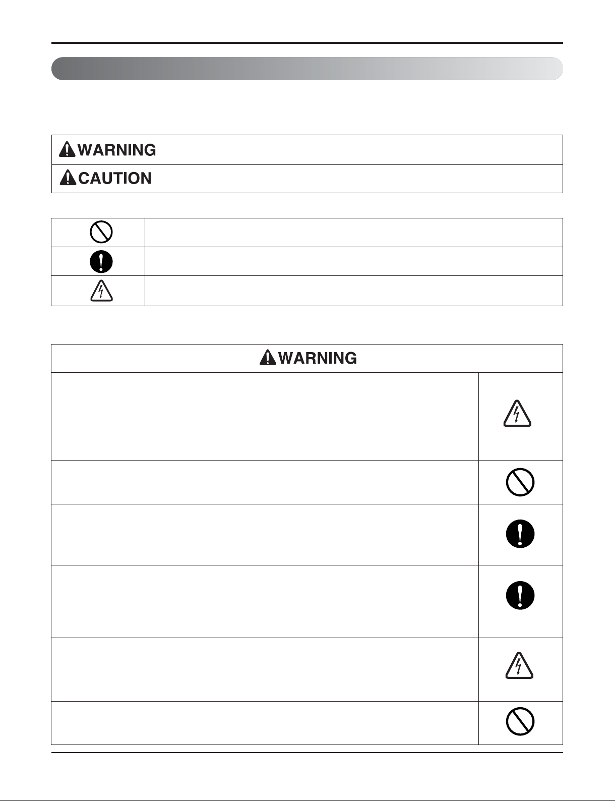
n Incorrect operation due to ignoring instruction will cause harm or damage. The seriousness is classified by the follow-
ing indications.
This symbol indicates the possibility of death or serious injury.
This symbol indicates the possibility of injury or damage to properties only.
n Meanings of symbols used in this manual are as shown below.
Be sure not to do.
Be sure to follow the instruction.
Dangerous Voltage
Be sure to disconnect the power cable plug from the plug socket before disassembling the equipment for a repair.Internal components and circuit boards are at
main potential when the equipment is connected to the power cables. This voltage is extremely dangerous and may cause death or severe injury if come in contact with it.
Do not touch the discharging refrigerant gas during the repair work.
The discharging refrigerant gas.The refrigerant gas can cause frostbite.
Release the refrigerant gas completely at a well-ventilated place first.
Otherwise, when the pipe is disconnected, refrigerant gas or refrigerating
machine oil discharges and it Can cause injury.
When the refrigerant gas leaks during work, execute ventilation. If the refrigerant
gas touches to a fire, poisonous gas generates. A case of leakage of the refrigerant and the closed room full with gas is dangerous because a shortage of oxygen
occurs. Be sure to execute ventilation.
When removing the front panel or cabinet, execute short-circuit and discharge
between high voltage capacitor terminals. If discharge is not executed, an electric
shock is caused by high voltage resulted in a death or injury.
Do not turn the air-conditioner ON or OFF by plugging or unplugging the power
plug. There is risk of fire or electrical shock.
- 5 -
Copyright ©2013 LG Electronics. Inc. All right reserved.
Only for training and service purposes
LGE Internal Use Only
Part 1 General Information
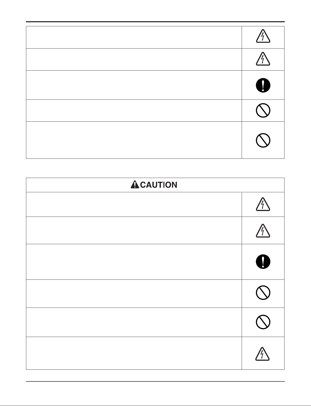
Do not turn on the breaker under condition that front panel and cabinet are
removed.
Be sure to earth the air conditioner with an earthing conductor connected to the
earthing terminal.
Conduct repair works after checking that the refrigerating cycle section has
cooled down sufficiently. Otherwise, working on the unit, the hot refrigerating
cycle section can cause burns.
Do not tilt the unit when removing panels. Otherwise, the water inside the unit
can spill and wet floor.
Do not use the welder in a well-ventilated place. Using the welder in an enclosed
room can cause oxygen deficiency.
Be sure to turn off power switch before connect or disconnect connector, or parts
damage may be occurred.
Do not use a defective or underrated circuit breaker. Use the correctly rated
breaker and fuse. Otherwise there is a risk of fire or electric shock.
Install the panel and the cover of control box securely. Otherwise there is risk of
fire or electric shock due to dust, water etc.
Indoor/outdoor wiring connections must be secured tightly and the cable should
be routed properly so that there is no force pulling the cable from the connection
terminals. Improper or loose connections can cause heat generation or fire.
Do not touch, operate, or repaire the product with wet hands. Hoding the plug by
hand when taking out. Otherwise there is risk of electric shock or fire.
Use a vacuum pump or Inert (nitrogen) gas when doing leakage test or air
purge. Do not compress air or Oxygen and Do not use Flammable gases.
Otherwise, it may cause fire or explosion.
- There is the risk of death, injury, fire or explosion.
- 6 -
Copyright ©2013 LG Electronics. Inc. All right reserved.
Only for training and service purposes
LGE Internal Use Only
Part 1 General Information
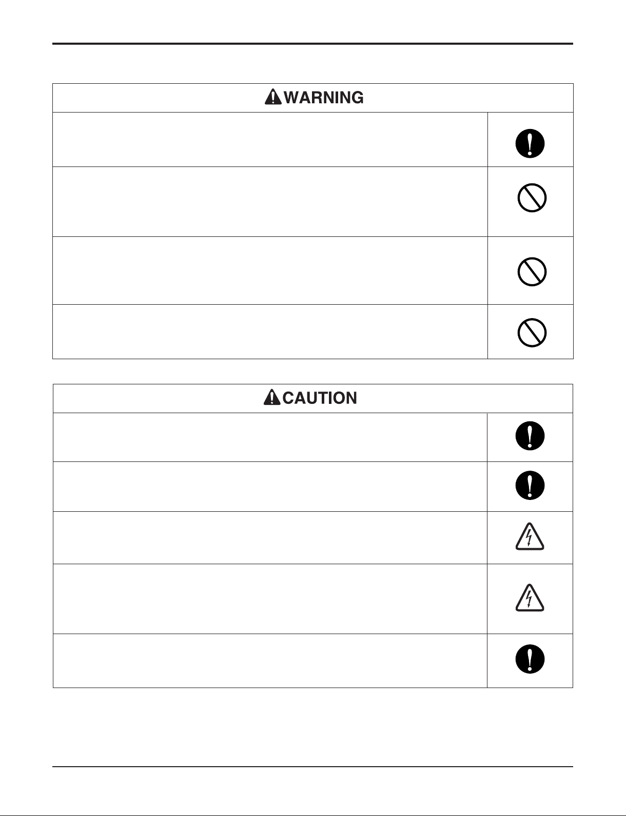
1.2 Inspections after Repair
Check to see if the parts are mounted correctly and wires are connected.
Improper installation and connections can cause an electric shock or an injury.
Check the installation platform or frame has corroded. Corroded installation platform or frame can cause the unit to fall, resulting in injury.
Be sure to check the earth wire is correctly connected.
After the work has finished, be sure to do an insulation tset to check the resistance is 2[Mohm] or more between the charge section and the non-charge metal
section (Earth position). If the resistance value is low, a disaster such as a leak or
electric shock is caused at userʼs side.
Check the drainage of the indoor unit after the repair. If drainage is faulty the
water to enter the room and wet floor.
Check to see if the power cable plug is not dirty or loose. If the plug is dust or
loose it can cause an electrical shock or fire.
Do not use a joined power cable or extension cable, or share the same power
outlet with other electrical appliances. otherwise, it can cause an electrical shock,
excessive heat generation or fire.
Do not insert hands or other objects through the air inlet or outlet while the product is operating. There are sharp and moving parts that could cause personal
injury.
Do not block the inlet or outlet of air flow. It may cause product failure
- 7 -
Copyright ©2013 LG Electronics. Inc. All right reserved.
Only for training and service purposes
LGE Internal Use Only
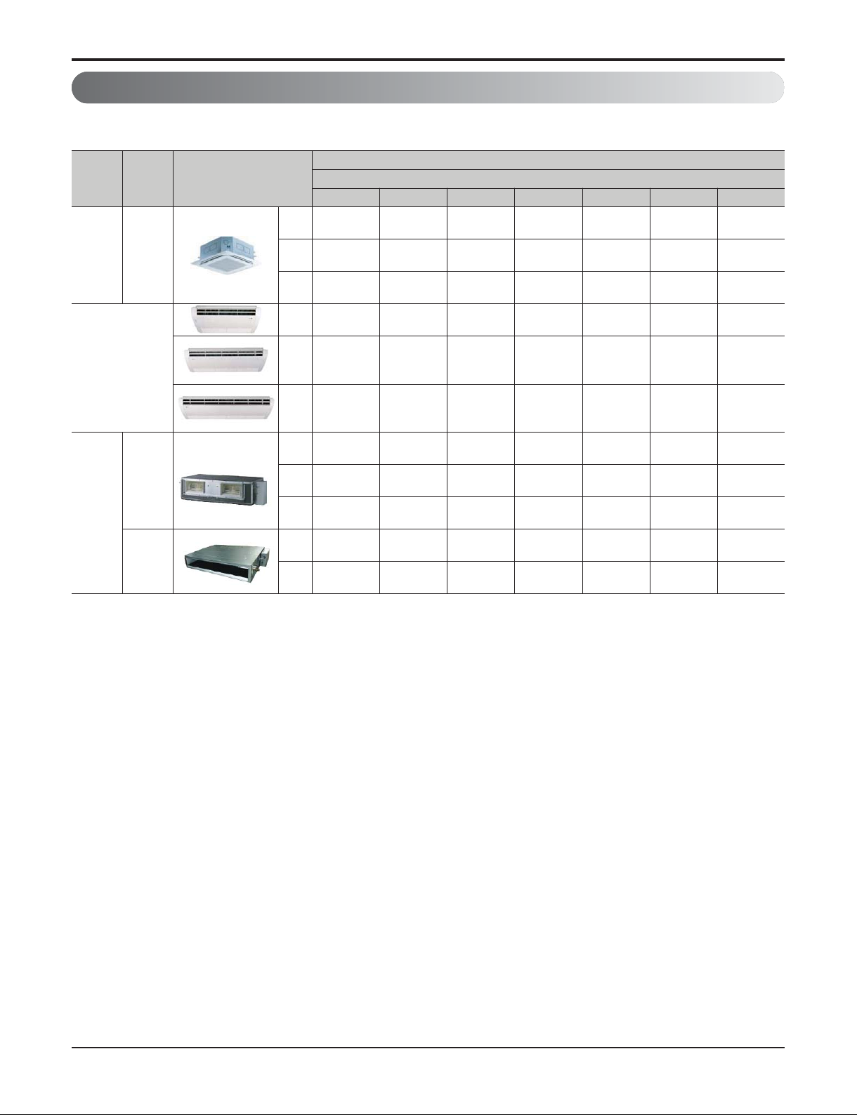
2. Model Line Up
Part 1 General Information
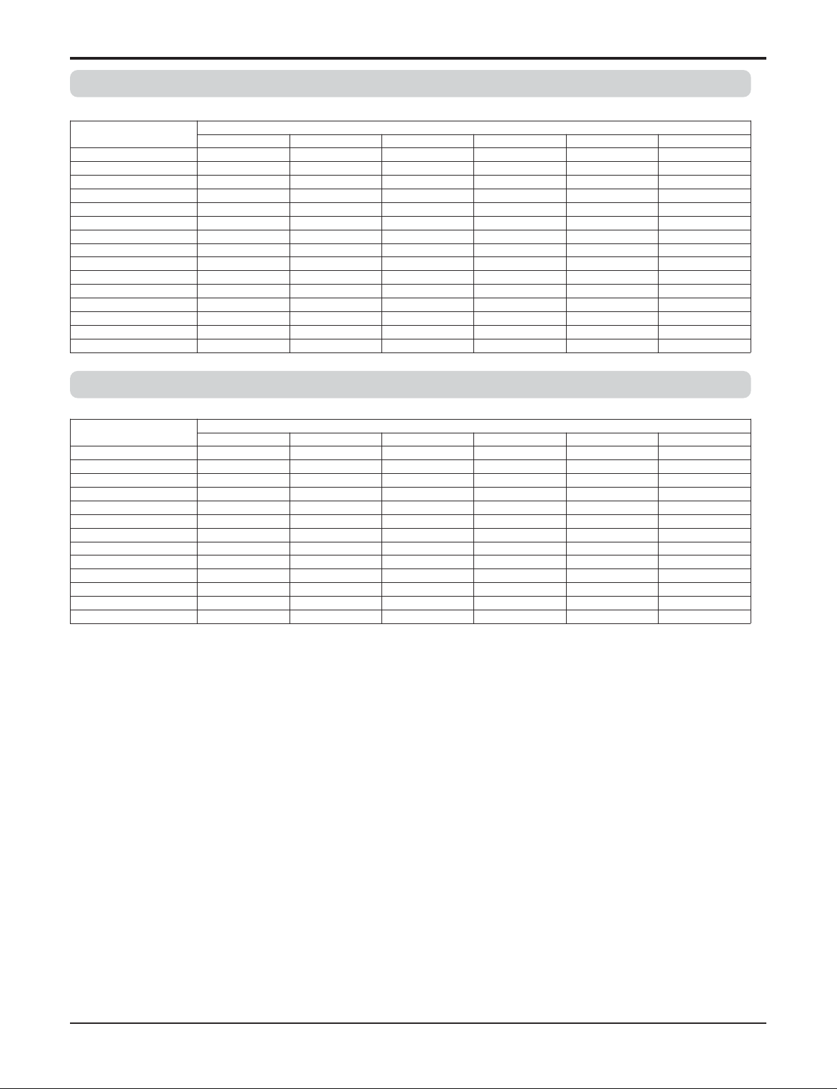
2.1 Indoor units
Category Type Chassis
Model Name
Capacity class, kW
5.0 6.0 7.0 10.5 12.5 14.1 15.8
Ceiling
cassette
4way
TP
ATNQ18GPLE3 ATNQ21GPLE3
TN
ATNQ24GNLE3
TM
ATNQ36GMLE3 ATNQ42GMLE3 ATUQ48GMLE3 ATUQ54GMLE3
Ceiling suspended
VJ
AVNQ18GJLA0 AVNQ21GJLA0 AVNQ24GJLA0
VK
AVNQ36GKLA0
VL
AVNQ42GLLA0 AVUQ48GLLA0 AVUQ54GLLA0
Ceiling
concealed
duct
High
static
pressure
BH
ABNQ18GHLA0 ABNQ21GHLA0
BG
ABNQ24GGLA0 ABNQ36GGLA0
BR
ABNQ42GRLA0 ABUQ48GRLA0 ABUQ54GRLA0
Low
static
pressure
L2
ABNQ18GL2A0 ABNQ21GL2A0
L3
ABNQ24GL3A0
- 8 -
Copyright ©2013 LG Electronics. Inc. All right reserved.
Only for training and service purposes
LGE Internal Use Only
Part 1 General Information
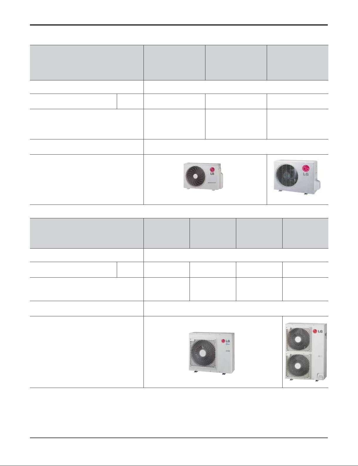
2.2 Outdoor units
Model Names
AUUQ18GH1
ATUQ18GPLE3
AVUQ18GJLA0
ABUQ18GHLA0
ABUQ18GL2A0
AUUQ21GH1
ATUQ21GPLE3
AVUQ21GJLA0
ABUQ21GHLA0
ABUQ21GL2A0
AUUQ24GH1
ATUQ24GNLE3
AVUQ24GJLA0
ABUQ24GGLA0
ABUQ24GL3A0
No. of connectable indoor units 1
Total capacity class index of
Connectable Indoor units
kW 5.0 6.0 7.0
Connectable indoor unit model names
ATNQ18GPLE3
AVNQ18GJLA0
ABNQ18GHLA0
ABNQ18GL2A0
ATNQ21GPLE3
AVNQ21GJLA0
ABNQ21GHLA0
ABNQ21GL2A0
ATNQ24GNLE3
AVNQ24GJLA0
ABNQ24GGLA0
ABNQ24GL3A0
Power supply
220-240V, 1Ø, 50Hz
220V, 1Ø, 60Hz
Chassis
Model Names
AUUQ36GH1
ATUQ36GMLE3
AVUQ36GKLA0
ABUQ36GGLA0
AUUQ42GH1
ATUQ42GMLE3
AVUQ42GLLA0
ABUQ42GRLA0
AUUQ48GH1
ATUQ48GMLE3
AVUQ48GLLA0
ABUQ48GRLA0
AUUQ54GH1
ATUQ54GMLE3
AVUQ54GLLA0
ABUQ54GRLA0
No. of connectable indoor units 1
Total capacity class index of
Connectable Indoor units
kW 10.5 12.5 14.1
15.8
Connectable indoor unit model names
ATNQ36GMLE3
AVNQ36GKLA0
ABNQ36GGLA0
ATNQ42GMLE3
AVNQ42GLLA0
ABNQ42GRLA0
ATUQ48GMLE3
AVUQ48GLLA0
ABUQ48GRLA0
ATUQ54GMLE3
AVUQ54GLLA0
ABUQ54GRLA0
Power supply
220-240V, 1Ø, 50Hz
220V, 1Ø, 60Hz
Chassis
- 9 -
Copyright ©2013 LG Electronics. Inc. All right reserved.
Only for training and service purposes
LGE Internal Use Only
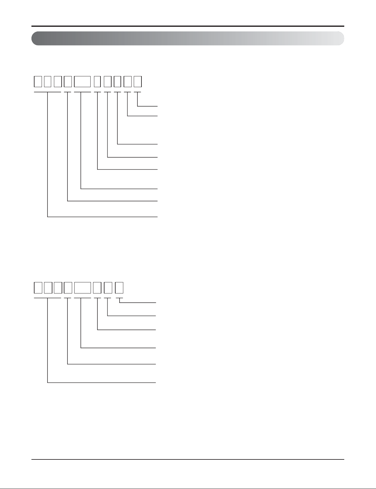
3. Nomenclature
3.1 Indoor Unit(Global)
Part 1 General Information
A T N Q24 G N L E 3
Serial Number
Functions
A : Basic
E : Elevation grille
Look : Basic
Chassis Name
Electrical Ratings
G : 220-240V, 1Ø, 50Hz / 220V, 1Ø, 60Hz
Capacity Code based on ‘kBtu/h’ units
A U U Q24 HG 1
Model Type
Q: Cooling Only
R410A Single A Indoor Unit
ATN : Ceiling cassette type indoor unit
AVN : Convertible, Ceiling and Floor type indoor unit
ABN : Ceiling concealed duct type indoor unit
Serial Number
High Efficiency model
Electrical Ratings
G : 220-240V, 1Ø, 50Hz / 220V, 1Ø, 60Hz
Capacity code
Model Type
Q : Cooling Only
R410A Single A Outdoor Unit

- 10 -
Copyright ©2013 LG Electronics. Inc. All right reserved.
Only for training and service purposes
LGE Internal Use Only
Part 2 Functions & Controls
1. List of Functions & Accessory ......................................................................................11
2. Air flow ............................................................................................................................15
2.1 Auto swing (left & right)...............................................................................................15
2.2 Auto swing (up & down) ..............................................................................................15
2.3 Chaos swing (up/down)...............................................................................................15
2.4 Air flow step.................................................................................................................16
2.5 Chaos wind (auto wind)...............................................................................................16
2.6 Jet Cool Mode Operation ............................................................................................16
2.7 Swirl wind Swing .........................................................................................................16
3. Air purifying ....................................................................................................................17
3.1 PLASMA Air Purifying System ....................................................................................17
4. Installation Functions ....................................................................................................18
4.1 E.S.P. (External Static Pressure) Setting ....................................................................18
4.2 High Ceiling operation.................................................................................................23
5. Reliability ........................................................................................................................24
5.1 Hot start.......................................................................................................................24
5.2 Self-diagnosis Function...............................................................................................24
6. Convenience Functions & Controls .............................................................................25
6.1 Cooling Operations .....................................................................................................25
6.2 Auto cleaning operation ..............................................................................................26
6.3 Auto changeover operation.........................................................................................26
6.4 Child Lock Function.....................................................................................................27
6.5 Group Control..............................................................................................................28
6.6 Sleep Timer Operation................................................................................................29
6.7 Timer(On/Off) ..............................................................................................................29
6.8 Weekly Program..........................................................................................................30
6.9 Two Thermistor Control...............................................................................................32
7. Special Function & KIT ..................................................................................................33
7.1 Low Ambient control....................................................................................................33
7.2 Space Control .............................................................................................................33
7.3 Auto Elevation Grille....................................................................................................33
Part 2 Functions & Controls
- 11 -
Copyright ©2013 LG Electronics. Inc. All right reserved.
Only for training and service purposes
LGE Internal Use Only
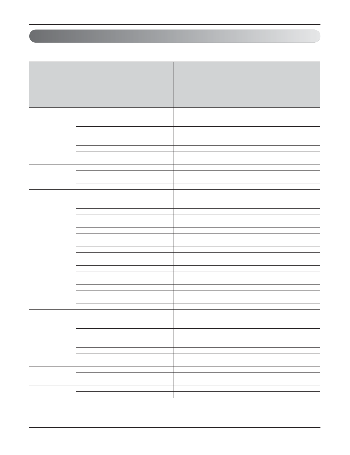
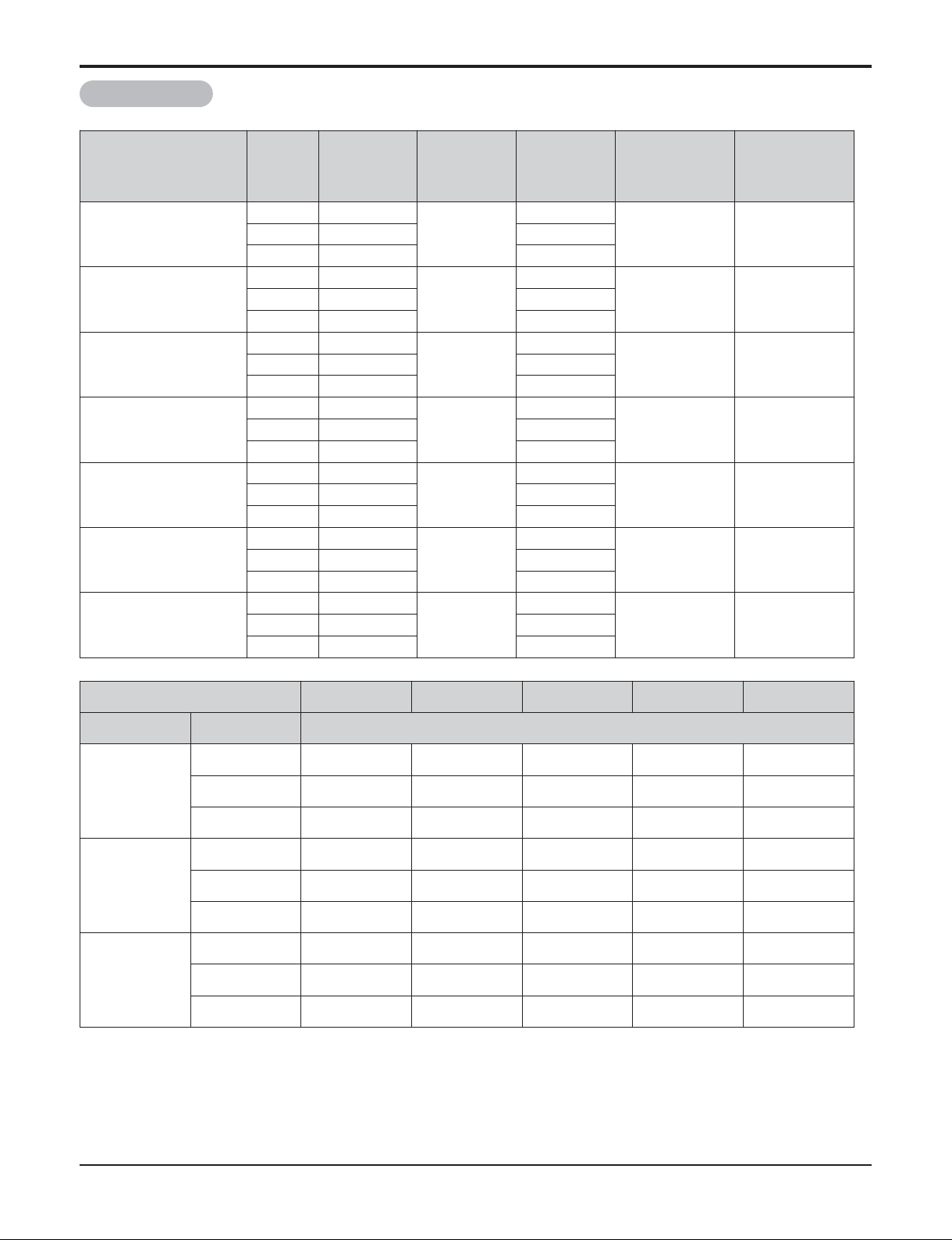
Category Functions
ATNQ18GPLE3
ATNQ21GPLE3
ATNQ24GNLE3
ATNQ36GMLE3
ATNQ42GMLE3
ATNQ48GMLE3
ATNQ54GMLE3
Air flow
Air supply outlet 4
Airflow direction control (left & right) X
Airflow direction control (up & down) Auto
Auto swing (left & right) X
Auto swing (up & down) O
Airflow steps (fan/cool/heat) 4 / 5 / 4
Chaos wind(auto wind) O
Jet cool/heat O / X
Swirl wind O
Air purifying
Triple filter (Deodorizing) X
Plasma air purifier PTPKM0
Allergy Safe filter X
Long-life prefilter (washable / anti-fungus) O
Installation
Drain pump O
E.S.P. control* X
Electric heater X
High ceiling operation* O
Auto Elevation Grille* PTEGM0
Reliability
Hot start O
Self diagnosis O
Soft dry operation O
Convenience
Auto changeover** O**
Auto cleaning X
Auto operation(artificial intelligence)** O**
Auto Restart O
Child lock* O
Forced operation O
Group control* O
Sleep mode O
Timer(on/off) O
Timer(weekly)* O
Two thermistor control* O
Individual
control
Wired remote controller O
Deluxe wired remote controller PQRCUDS0 / PQRCUDS0B / PQRCUDS0S
Simple wired remote controller PQRCVCL0Q / PQRCVCL0QW
Simple Wired remote controller(for hotel use)
PQRCHCA0Q / PQRCHCA0QW
Wireless remote controller PQWRHDF0
CAC network
function
General central controller (Non LGAP) X
Network Solution(LGAP) O
Dry contact PQDSA(1)/PQDSB(1) / PQDSBC
PI 485(for Indoor Unit) X
Special
function kit
Zone controller X
CTI(Communication transfer interface) X
Electronic thermostat X
Others
Remote temperature sensor PQRSTA0
Telecom shelter controller X
Part 2 Functions & Controls
1. List of Functions & Accessory
1. 4-Way Ceiling Cassette Indoor
- 12 -
Copyright ©2013 LG Electronics. Inc. All right reserved.
Only for training and service purposes
LGE Internal Use Only
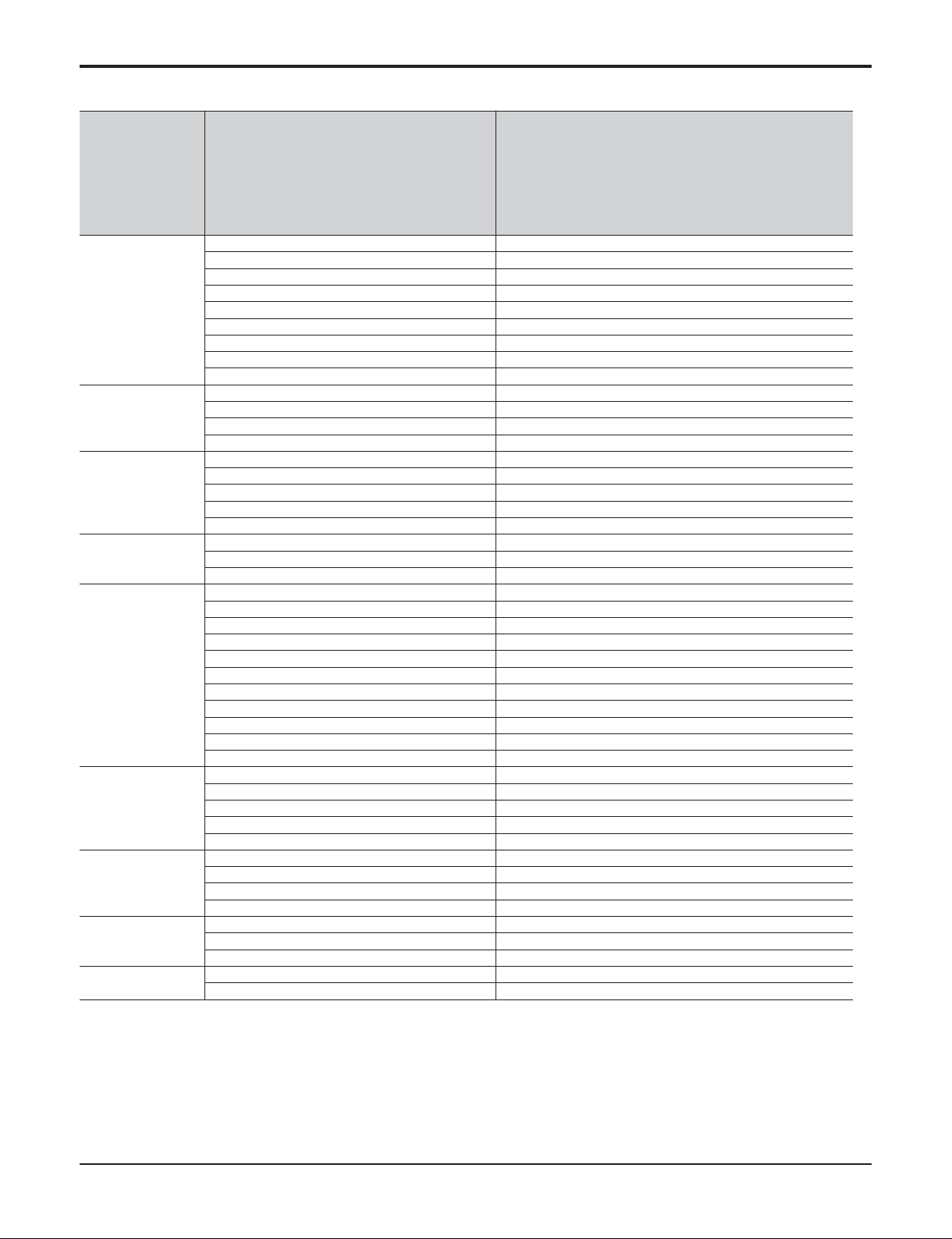
Part 2 Functions & Controls
2. Ceiling Concealed Duct Indoor
Category Functions
ABNQ18GHLA0, ABUQ18GL2A0
ABNQ21GHLA0, ABUQ21GL2A0
ABNQ24GGLA0, ABUQ24GL3A0
ABNQ36GGLA0
ABNQ42GRLA0
ABNQ48GRLA0
ABNQ54GRLA0
Air flow
Air supply outlet 2
Airflow direction control (left & right) X
Airflow direction control (up & down) X
Auto swing (left & right) X
Auto swing (up & down) X
Airflow steps (fan/cool/heat) 3 / 3 / 3
Chaos wind(auto wind) X
Jet cool/heat O / X
Swirl wind X
Air purifying
Triple filter (Deodorizing) X
Plasma air purifier X
Allergy Safe filter X
Long-life prefilter (washable / anti-fungus) O
Installation
Drain pump ABDPG
E.S.P. control* O
Electric heater X
High ceiling operation* X
Auto Elevation Grille* X
Reliability
Hot start O
Self diagnosis O
Soft dry operation O
Convenience
Auto changeover** O**
Auto cleaning X
Auto operation(artificial intelligence)** O**
Auto Restart O
Child lock* O
Forced operation X
Group control* O
Sleep mode X
Timer(on/off) O
Timer(weekly)* O
Two thermistor control* O
Individual
control
Standard Wired remote controller O
Deluxe wired remote controller X
Simple wired remote controller X
Simple Wired remote controller(for hotel use) X
Wireless remote controller X
CAC network
function
General central controller (Non LGAP) X
Network Solution(LGAP) O
Dry contact PQDSA(1)/PQDSB(1) / PQDSBC
PI 485(for Indoor Unit) X
Special
function kit
Zone controller ABZCA
CTI(Communication transfer interface) X
Electronic thermostat X
Others
Remote temperature sensor PQRSTA0
Telecom shelter controller X
- 13 -
Copyright ©2013 LG Electronics. Inc. All right reserved.
Only for training and service purposes
LGE Internal Use Only
3. Ceiling & floor
Type Ceiling Suspended
Category Functions
AVNQ18GJLA0
AVNQ21GJLA0
AVNQ24GJLA0
AVNQ36GKLA0
AVNQ42GLLA0
AVNQ48GLLA0
AVNQ54GLLA0
Air flow
Air supply outlet 1
Airflow direction control (left & right) Manual
Airflow direction control (up & down) Auto
Auto swing (left & right) X
Auto swing (up & down) O
Airflow steps (fan/cool/heat) 3 / 4 / 3
Chaos wind(auto wind) O
Jet cool/heat O / X
Swirl wind X
Air purifying
Triple filter (Deodorizing) X
Plasma air purifier X
Allergy Safe filter X
Long-life prefilter (washable / anti-fungus) O
Installation
Drain pump X
E.S.P. control* X
Electric heater X
High ceiling operation* O
Auto Elevation Grille* X
Reliability
Hot start O
Self diagnosis O
Soft dry operation O
Convenience
Auto changeover** O**
Auto cleaning X
Auto operation(artificial intelligence)** O**
Auto Restart O
Child lock* O
Forced operation O
Group control* O
Sleep mode O
Timer(on/off) O
Timer(weekly)* O
Two thermistor control* O
Individual
control
Wired remote controller PQRCVSL0/PQRCVSL0QW
Deluxe wired remote controller X
Simple wired remote controller X
Simple Wired remote controller(for hotel use)
X
Wireless remote controller O
Network
function
General central controller (Non LGAP) X
Network Solution(LGAP) O
Dry contact
PQDSA(1)/PQDSB(1) / PQDSBC
PI 485(for Indoor Unit) X
Special
function kit
Zone controller X
CTI(Communication transfer interface) X
Electronic thermostat X
Others
Remote temperature sensor PQRSTA0
Telecom shelter controller X
Part 2 Functions & Controls
- 14 -
Copyright ©2013 LG Electronics. Inc. All right reserved.
Only for training and service purposes
LGE Internal Use Only
Part 2 Functions & Controls
4. Outdoor
Category Functions 5 / 6 kW
7 kW ↑
Reliability
Defrost / Deicing X X
High pressure switch X X
Low pressure switch X X
Phase protection X X
Restart delay (3-minutes) O O
Self diagnosis O O
Soft start O O
Test function O X
Convenience Night Silent Operation O O
network
function
Network solution(LGAP) X O
Device 5 / 6 kW
7 kW ↑
Central
Controller
Simple Controller X PQCSB101S0
Function controller X PQCSB101S0 + PQCSC101S0
Function Scheduler X PQCSB101S0 + PQCSD130A0
AC Ez X PQCSZ250S0
AC Smart ll X PQCSW320A1E
Option Kit (SD card type) X PQCSE341A0 / PQCSE342A0
ACP(Advanced Control Platform) X PQCPA11A0E / PQCPB11A0E
AC Manager X PQCSS520A0E
PI485 X PMNFP14A0 / PMNFP14A1
DO(Digital Output) Kit X PQNFP00T0
BNU (Building
Network Unit)
LONWORKS Gateway X PQNFB16A1
BACnet Gateway X PQNFB17B0
Installation
Y branch X X
Header branch X X
Air Guide X X
ODU Dry Contact X X
Low Ambient Kit O (Logical operation) O (Logical operation)
- 15 -
Copyright ©2013 LG Electronics. Inc. All right reserved.
Only for training and service purposes
LGE Internal Use Only
2. Air flow
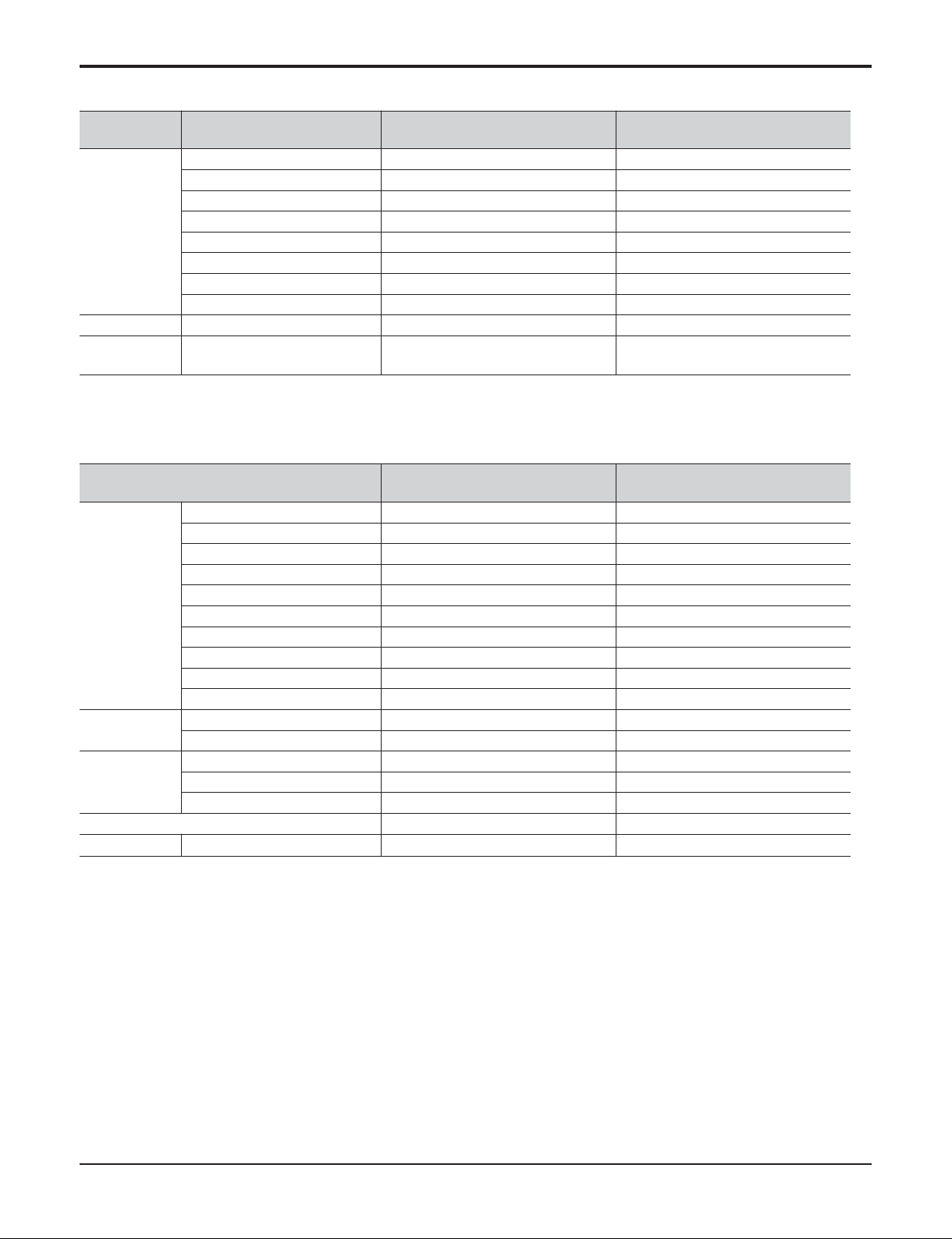
2.1 Auto swing (left & right)
• By the horizontal airflow direction control key input, the left/right louver automatically operates with the auto swing or it
is fixed to the desired direction.
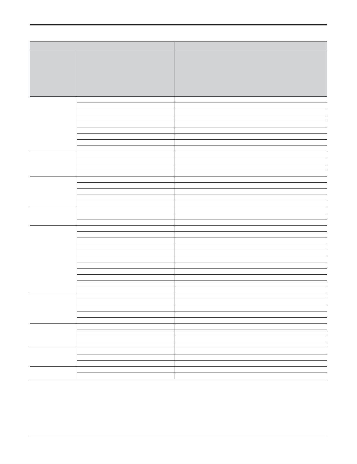
2.2 Auto swing (up & down)
• By the auto swing key input, the upper/lower vane automatically operates with the auto swing or it is fixed to the
desired direction.
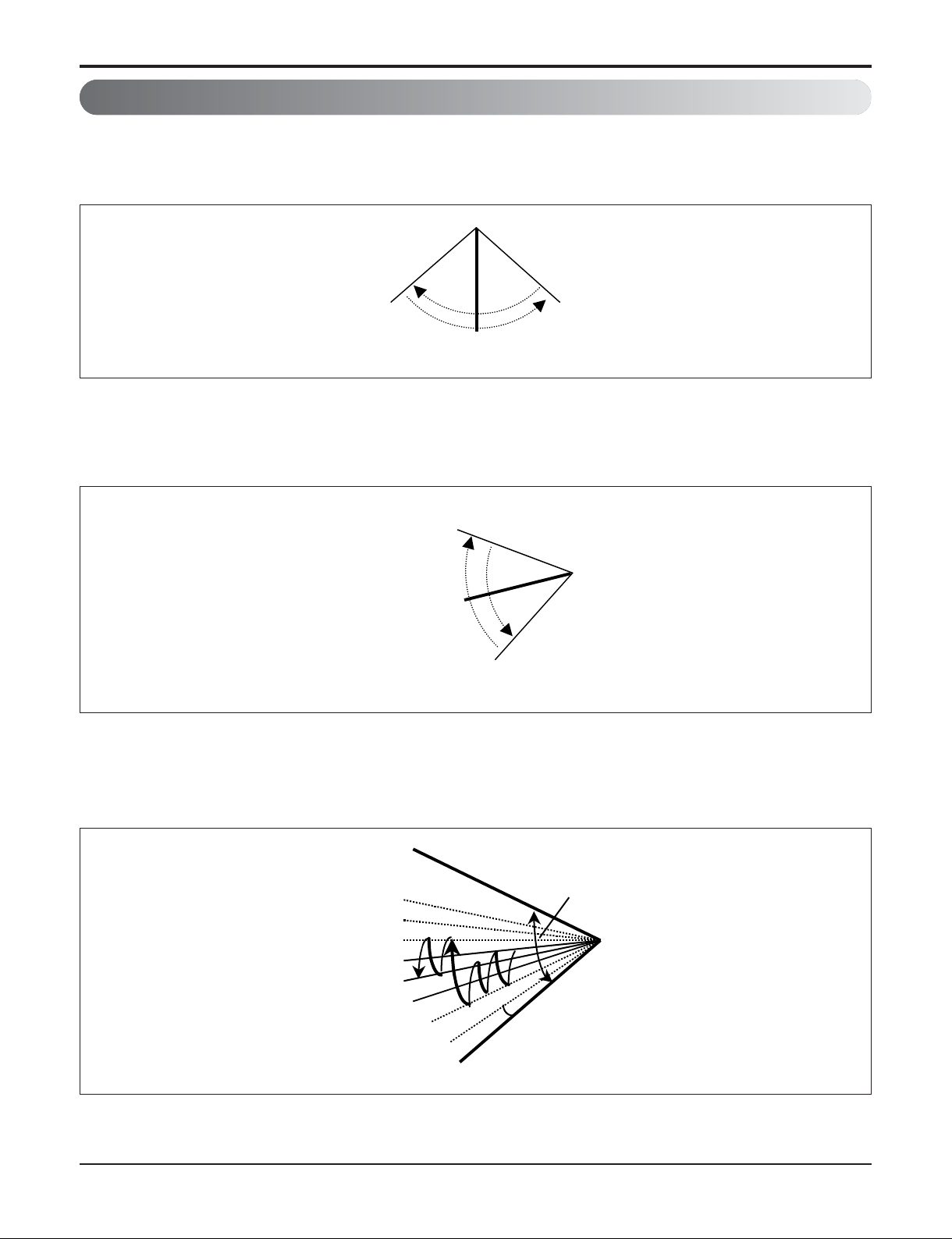
2.3 Chaos swing (up/down)
• By the Chaos swing key input, the upper/lower vane automatically operates with the chaos swing or it is fixed to the
desired direction.
NOTE: Some Models are different by swing width and swing pattern.
Part 2 Functions & Controls
RightLeft
110° ~ 120°
Close
110° ~ 120°
Open
CLOSED
Mode9
Mode8
Mode7
Mode6
Mode5
Mode4
Mode3
Mode2
110~120°
7~8°
OPEN
- 16 -
Copyright ©2013 LG Electronics. Inc. All right reserved.
Only for training and service purposes
LGE Internal Use Only
Part 2 Functions & Controls
2.4 Air flow step
• Indoor fan motor control have 6 steps.
• Air volume is controlled "SH", "H", "Med", Low" by remote controller.
• "LL" step is selected automatically in Hot start operation.
2.5 Chaos wind (auto wind)
• When "Auto" step selected and then operated, the high, medium, or low speed of the airflow mode is operated for
2~15 sec. randomly by the Chaos Simulation
2.6 Jet Cool Mode Operation
• While in heating mode or Fuzzy operation, the Jet Cool key cannot be input.
When it is input while in the other mode operation (cooling, dehumidification, ventilation), the Jet Cool mode is operated.
• In the Jet Cool mode, the indoor fan is operated at super-high speed for 30 min. at cooling mode operation.
• In the Jet Cool mode operation, the room temperature is controlled to the setting temperature, 18°C.
• When the sleep timer mode is input while in the Jet Cool mode operation, the Jet Cool mode has the priority.
• When the Jet Cool key is input, the upper/lower vanes are reset to those of the initial cooling mode and then operated
in order that the air outflow could reach further.
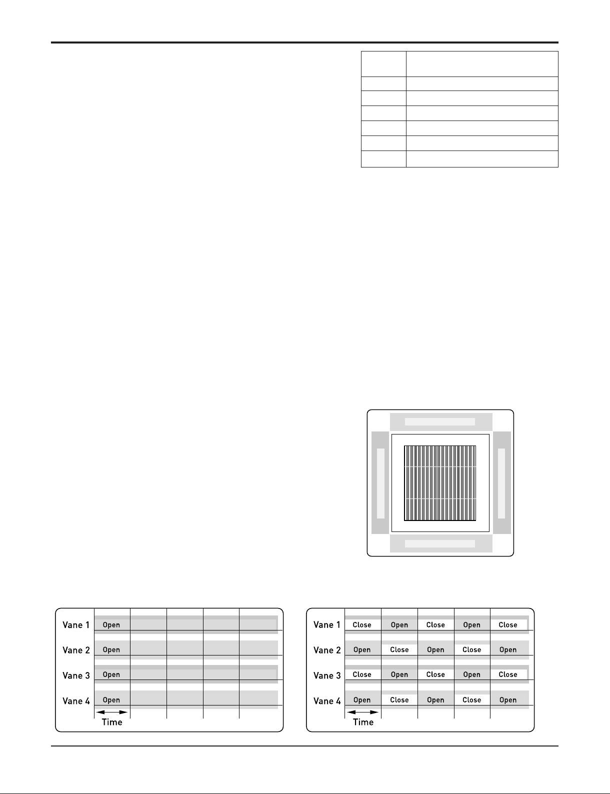
2.7 Swirl wind Swing
• It is the function for comfort cooling/heating operation.
• The diagonal two louvers are opened the more larger
than the other louvers. After one minute, it is opposite.
• Comparison of Air Flow Types
4-Open (conventional) Swirl Swing (New)
LL Very low, In heating mode
L Low
M Med
H High
SH Super high
Auto Chaos wind
Step Discription
Vane 4
Vane 2
Vane 1 Vane 3
- 17 -
Copyright ©2013 LG Electronics. Inc. All right reserved.
Only for training and service purposes
LGE Internal Use Only
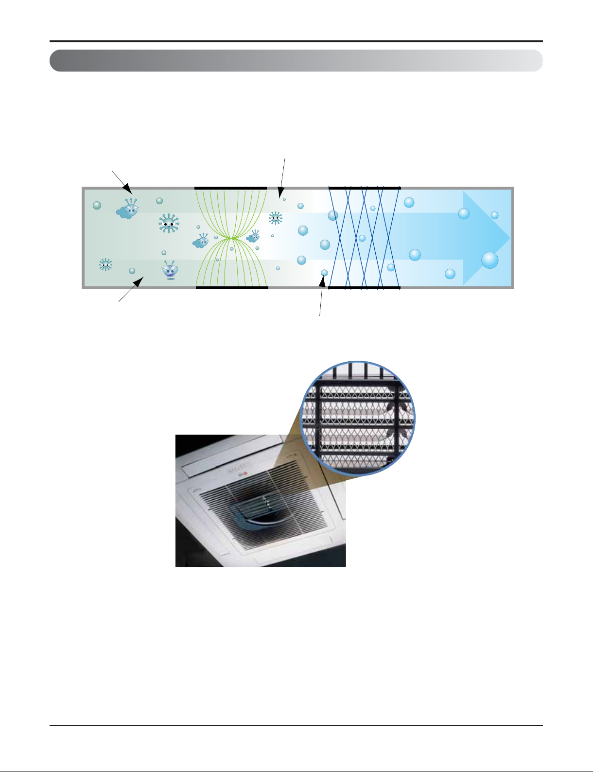
3.1 PLASMA Air Purifying System
The PLASMA Air Purifying System not only removes microscopic contaminants and dust, but also removes house
mites, pollen, and pet fur to help prevent allergic diseases like asthma. This filter that can be used over and over again
by simply washing with water.
3. Air purifying
Ionizer
Photo-Catalyst Coated Mesh
Dust particles
Odour
Dust electrode discharge
Odour molecule
Generating plasma
+
+
+
+
Polluted Air
Purified fresh Air
+4.8KV discharge
+
Part 2 Functions & Controls
- 18 -
Copyright ©2013 LG Electronics. Inc. All right reserved.
Only for training and service purposes
LGE Internal Use Only
Part 2 Functions & Controls
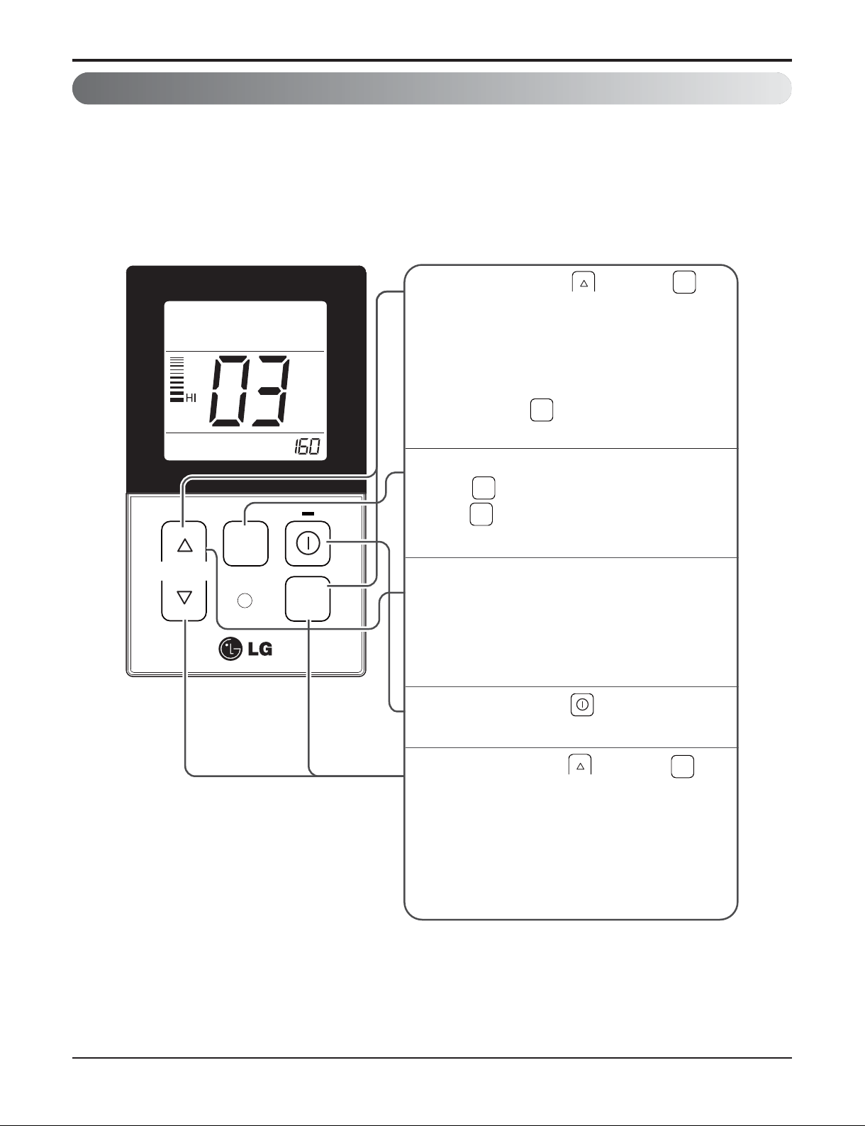
4.1 E.S.P. (External Static Pressure) Setting
4. Installation Functions
This is the function that decides the strength of the wind for each wind level and because this function is to make
the installation easier.
- If you set ESP incorrectly, the air conditioner may malfunction.
- This setting must be carried out by a certificated-technician.
- Precaution shall be taken not to alter the E.S.P value corresponded to each air flow section.
- E.S.P value can be varied according to the products.
- In the case of going to the next air flow rate stage by pressing the fan-speed button during the setup of the E.S.P
value, the E.S.P value of previous air flow rate will be maintained by remembering the E.S.P value prior to the
shift.
OPER
When pressing the button and
1
button simultaneously for more than 3
seconds, the system will be entered into the
installer setting mode.
- After entering into the installer setting
mode, select the E.S.P code value by
OPER
pressing the button.
MODE
* E.S.P code value : 03
MODE
TEMP
FAN
SPEED
OPER
MODE
Select the desired air flow rate with
2
FAN
SPEED
the button. Whenever pressing
FAN
the button, [Lo→Med→Hi] will be
SPEED
indicated.
Select the desired air flow rate value with
3
the temperature up(s), down(t) button.
* E.S.P value range : 0~255
- E.S.P value will be indicated at the upper
right section of the display window.
When pressing the button, currently
4
established E.S.P value will be set up.
When pressing the button and
5
button simultaneously for more than 3
OPER
MODE
seconds after the setting has been
completed, the setting mode will be released.
- If there isn’t any button input for more than
25 seconds, the installer setting mode will
also be released.
- 19 -
Copyright ©2013 LG Electronics. Inc. All right reserved.
Only for training and service purposes
LGE Internal Use Only
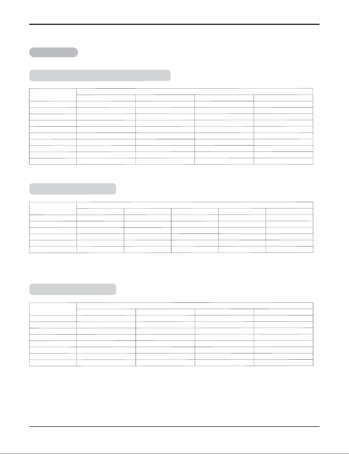
E.S.P. setting value (reference)
[ Notes ]
1. To get the desired Airflow & E.S.P. combination from the table set the matching value from the table. Value other than
that in table will not give the combinations of airflow & E.S.P. which are mentioned in the table.
2. Table data is based at 230V. According to the fluctuation of voltage, air flow rate varies.
Table 1
Part 2 Functions & Controls
Setting Value
Static Pressure[mmAq(Pa)]
2.5(25) 4(39) 6(59) 8(78)
100 12.8 - - 105 13.9 - - 110 15.2 12.7 - 115 16.5 14.0 - 120 17.8 15.3 12.7 125 - 16.5 14.0 130 - 17.8 15.3 12.6
135 - - 16.5 13.5
140 - - 17.5 14.5
145 - - - 16.5
(Unit: CMM)
(Unit: CMM)
Setting Value
Static Pressure[mmAq(Pa)]
4(49) 6(59) 8(78) 10(98)
100 20.8 - - 105 23.2 19.5 - 110 26.0 21.5 - 115 - 23.5 19.1 120 - 26.3 21.6 125 - - 24.0 19.9
130 - - 27.0 22.7
135 - - - 25.9
(Unit: CMM)
Models : ABNQ18GHLA0, ABNQ21GHLA0
Models :
ABNQ24GGLA0
Models :
ABNQ36GGLA0
Setting Value
Static Pressure[mmAq(Pa)]
6(59) 8(78) 10(98) 12(118) 14(137)
80 14.8 - - - -
90 19.0 14.4 - - 100 23.3 19.7 13.9 - 110 26.9 24.3 19.8 14.1 120 31.2 28.2 25.2 20.1 14.4
130 34.9 32.4 29.5 25.4 20.5
- 20 -
Copyright ©2013 LG Electronics. Inc. All right reserved.
Only for training and service purposes
LGE Internal Use Only
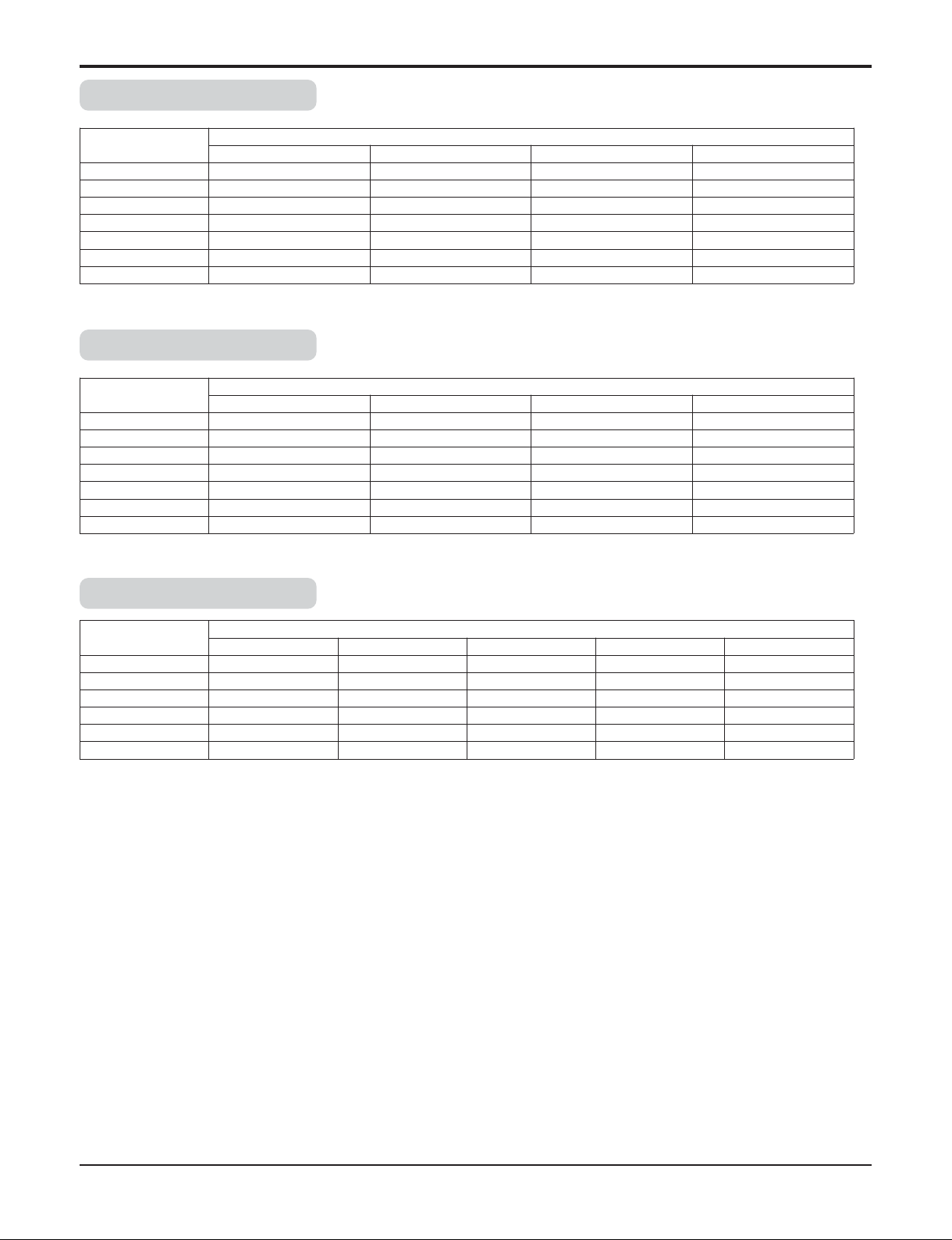
Part 2 Functions & Controls
Setting Value
Static Pressure[mmAq(Pa)]
6(59) 8(78) 10(98) 12(118)
85 31.5 - - 90 36.3 29.8 - 95 41.3 34.5 28.4 -
100 45.4 39.7 33.5 27.3
105 - 44.1 38.6 33.1
110 - - 44.2 38.9
115 - - - 44.7
(Unit: CMM)
Setting Value
Static Pressure[mmAq(Pa)]
6(59) 8(78) 10(98) 12(118)
85 31.5 - - 90 36.3 29.8 - 95 41.3 34.5 28.4 -
100 45.4 39.7 33.5 27.3
105 - 44.1 38.6 33.1
110 - - 44.2 38.9
115 - - - 44.7
(Unit: CMM)
Setting Value
Static Pressure[mmAq(Pa)]
6(59) 8(78) 10(98) 12(118) 14(137)
95 41.3 - - - -
100 45.4 39.7 - - 105 49.5 44.1 38.6 - 110 - 48.5 44.2 38.9 115 - - 49.8 44.7 42.2
120 - - - 50.5 48.1
(Unit: CMM)
Models :
ABNQ42GRLA0
Models :
ABNQ48GRLA0
Models :
ABNQ54GRLA0
※ ABNQ42GRLA0 / ABNQ48GRLA0 As far as possible do not set ESP 82,83
- 21 -
Copyright ©2013 LG Electronics. Inc. All right reserved.
Only for training and service purposes
LGE Internal Use Only
Part 2 Functions & Controls
Models: ABNQ18GL2A0 / ABNQ21GL2A0
Models: ABNQ24GL3A0
Setting Value
Static Pressure(mmAq(Pa))
0 (0) 1 (10) 2 (20) 3 (30) 4 (40) 5 (50)
75 6.50 - - - - 80 7.34 6.70 - - - 85 8.20 7.55 6.69 - - 90 9.07 8.43 7.56 6.47 - 95 9.96 9.32 8.45 7.36 - -
100 10.87 10.22 9.36 8.27 6.96 105 11.79 11.15 10.28 9.19 7.89 6.35
110 12.73 12.09 11.22 10.14 8.83 7.30
115 13.69 13.05 12.18 11.09 9.78 8.25
120 14.67 14.02 13.16 12.07 10.76 9.23
125 15.66 15.01 14.15 13.06 11.75 10.22
130 16.67 16.02 15.16 14.07 12.76 11.23
135 - - 16.18 15.10 13.79 12.26
140 - - - 16.14 14.83 13.30
145 - - - - 15.89 14.36
(Unit : CMM)
(Unit : CMM)
Setting Value
Static Pressure(mmAq(Pa))
0 (0) 1 (10) 2 (20) 3 (30) 4 (40) 5 (50)
85 10.19 - - - - 90 12.18 10.71 11.09 - - 95 13.81 12.34 12.19 - - -
100 15.16 13.69 13.38 10.71 - 105 16.30 14.83 14.36 11.85 - 110 17.31 15.85 15.23 12.86 10.97 115 18.27 16.80 16.07 13.82 11.93 120 19.26 17.79 16.93 14.80 12.91 10.49
125 20.34 18.87 17.89 15.88 13.99 11.57
130 21.60 20.13 19.01 17.14 15.25 12.83
135 - 21.64 20.36 18.66 16.76 14.35
140 - - 22.01 20.50 18.61 16.19
145 - - - 22.75 20.86 18.44
Note :
1. The above table shows the correlation between the air rates and E.S.P.
- 22 -
Copyright ©2013 LG Electronics. Inc. All right reserved.
Only for training and service purposes
LGE Internal Use Only
Part 2 Functions & Controls
Table 2
Model Mode Set value
Standard ESP
(mmAq(Pa))
CMM
Lower Limit of
External Static
Pressure
(mmAq(Pa))
Upper Limit of
External Static
Pressure
(mmAq(Pa))
ABNQ18GHLA0
Hi
8 (78)
16.5
2.5(25) 8 (78)Mid 14.5
Low 13.0
ABNQ21GHLA0
Hi
8 (78)
16.5
2.5(25) 8 (78)Mid 14.5
Low 13.0
ABNQ24GGLA0
Hi
8 (78)
16.5
2.5(25) 8 (78)Mid 14.5
Low 13.0
ABNQ36GGLA0
Hi
10 (98)
32.0
4.0(39) 10 (98)Mid 29.0
Low 26.0
ABNQ42GRLA0
Hi
10 (98)
28.0
5.0(49) 10 (98)Mid 26.0
Low 32.0
ABNQ48GRLA0
Hi
10 (98)
40.0
5.0(49) 10 (98)Mid 35.0
Low 30.0
ABNQ54GRLA0
Hi
10 (98)
50.0
5.0(49) 10 (98)Mid 45.0
Low 40.0
1450
1400
1340
1450
1400
1340
1270
1210
1090
1370
1310
1260
1060
1020
990
1100
1060
1030
1240
1200
1150
[Notes]
1. To get the desired Airflow & E.S.P. combination from the table set the matching value from the table. Value other than
that in table will not give the combinations of airflow & E.S.P. which are mentioned in the table.
2. Table data is based at 230V. According to the fluctuation of voltage, air flow rate varies.
Static pressure(mmAq) 0 1 2 3 4
Model Step(Hi/Mid/Low) Setting value
ABNQ18GL2A0
15 CMM 90 97 105 114 122
12.5 CMM 82 90 99 109 119
10 CMM 75 84 93 103 114
ABNQ21GL2A0
17.5 CMM 90 97 105 114 122
14 CMM 82 90 99 109 119
12 CMM 75 84 93 103 114
ABNQ24GL3A0
20 CMM 110 117 125 129 -
16 CMM 100 107 115 121 127
12 CMM 90 97 105 114 122
- 23 -
Copyright ©2013 LG Electronics. Inc. All right reserved.
Only for training and service purposes
LGE Internal Use Only
Part 2 Functions & Controls
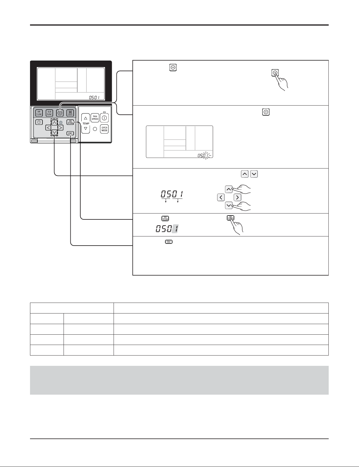
4.2 High Ceiling operation
Function Code Thermistor setting
Select ceiling height value by pressing button. (01:Low,
02:Medium, 03:High, 04:Very high)
3
Press button to save.
4
5
If moving to ceiling height selection menu by pressing button,
it indicates as picture below.
2
If pressing button long for 3 seconds, it enters into
remote controller setter setup mode.
- If pressing once shortly, it enters into user setup mode.
Please press more than 3 seconds for sure.
1
Pressing button will exit settings mode.
❈ After setup, it automatically gets out of setup mode if there is no button input
for 25 seconds.
❈ When exiting without pressing set button, the manipulated value is not
reflected.
This function is to adjust FAN Airflow rate according to ceiling height (For ceiling type product)
• Ceiling height setting is available only for some products.
• Ceiling height of ʻVery highʼ function may not exist depending on the indoor unit.
• Refer to the product manual for more details.
<Ceiling Height Selection Table>
Ceiling Height Level Description
01 Low Decrease the indoor airflow rate 1 step from standard level
02 Medium Set the indoor airflow rate as standard level
03 High Increase indoor airflow rate 1 step from standard level
04 Very high Increase indoor airflow rate 2 steps from standard level
- 24 -
Copyright ©2013 LG Electronics. Inc. All right reserved.
Only for training and service purposes
LGE Internal Use Only
Part 2 Functions & Controls
5.1 Self-diagnosis Function
• The air conditioner installed can self-diagnosed its error status and then transmits the result to the central control.
Therefore, a rapid countermeasure against failure of the air conditioner allows easy management and increases the
usage life of air conditioner.
• Refer to trouble shooting guide.
5.2 Soft dry operation
• When the dehumidification operation input by the remote control is received, the intake air temperature is detected and
the setting temp is automatically set according to the intake air temperature.
• While compressor off, the indoor fan repeats low airflow speed and stop.
• While the intake air temp is between compressor on temp. and compressor off temp., 10-min dehumidification operation and 4-min compressor off repeat.
Compressor ON Temp. ‘ Setting Temp+0.5°C
Compressor OFF Temp. ‘ Setting Temp-0.5°C
• In 10-min dehumidification operation, the indoor fan operates with the low airflow speed.
5. Reliability
Intake air Temp. Setting Temp.
26°C ≤ intake air temp. 25°C
24°C ≤ intake air temp.< 26°C intake air temp. -1°C
22°C ≤ intake air temp. < 24°C intake air temp. -0.5°C
18°C ≤ intake air temp. < 22°C intake air temp.
intake air temp. < 18°C 18°C

- 25 -
Copyright ©2013 LG Electronics. Inc. All right reserved.
Only for training and service purposes
LGE Internal Use Only
6.1 Cooling Operations
6.1.1 Cooling Mode
• Operating frequency of compressor depends on the load condition, like the difference between the room temp. and
the set temp., frequency restrictions.
• If the compressor operates at some frequency, the operating frequency of compressor cannot be changed within 30
seconds. ( not emergency conditions)
• Compressor turned off when
- intake air temperature is in between ±0.5°C of the setting temp. limit for three minutes continuously.
- intake air temperature reaches below 1.0°C of the temperature of setting temp..
• Compressors three minutes time delay.
- After compressor off, the compressor can restart minimum 3 minutes later.
6. Convenience Functions & Controls
Part 2 Functions & Controls
- 26 -
Copyright ©2013 LG Electronics. Inc. All right reserved.
Only for training and service purposes
LGE Internal Use Only
6.3 Auto restart Operation
• Whenever there is electricity failure to the unit, and after resumption of the power, unit will start in the same mode prior
to the power failure. Memorized condition are on / off condition, operating mode (cooling/ heating), set temperature and
fan speed. The unit will memorize the above conditions and start with same memorized condition.
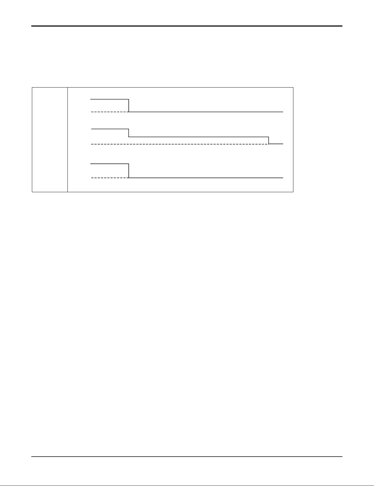
6.2 Auto cleaning operation
• Function used to perform Self Cleaning to prevent the Unit from Fungus and bad odor.
• Used after the Cooling Operation before turning the unit off, clean the Evaporator and keep it dry for the next operation.
• The function is easy to operate as it is accessed through the Remote controller.
Unit
Operation
ON
OFF
Comp.
Indoor
Fan
ON
OFF
ON
OFF
Setting step
OFFL Low
Setting step
(Cooling Only)
Part 2 Functions & Controls
- 27 -
Copyright ©2013 LG Electronics. Inc. All right reserved.
Only for training and service purposes
LGE Internal Use Only
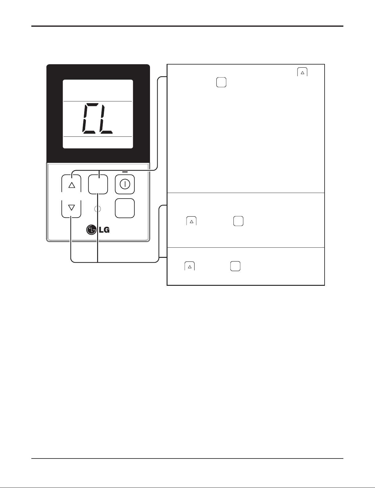
6.4 Child Lock Function
It is the function to use preventing children or others from careless using.
Part 2 Functions & Controls
During the operation, when pressing the
1
button and button for approx. 3
seconds, the ‘Child Lock’ Function can be
used.
- At the time of initial setting of the ‘Child Lock’,
the ‘CL’ Will be indicated approx. 3 seconds at
the temperature Display section before
resuming to the previous mode. After the
setting of the ‘CL’, if another button is setup,
the button can not be recognized as the ‘CL’ is
indicated at the temperature display section for
FA N
SPEED
TEMP
OPER
MODE
approx. 3 seconds.
If the ‘CL’ function is wanted to be used under
2
the operation standby state, press the
button and Button for approx.
3 seconds under the standby mode state and
the system will be the ‘CL’ state.
FAN
SPEED
FAN
SPEED
As for the releasing method, when pressing the
3
Button and button for approx. 3
FAN
SPEED
seconds, the ‘CL’ function can be released.
- 28 -
Copyright ©2013 LG Electronics. Inc. All right reserved.
Only for training and service purposes
LGE Internal Use Only
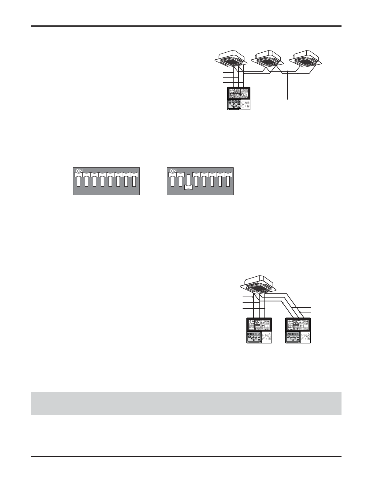
6.5 Group Control
GND
GND
12V
Signal wire
Signal wire
GND
12V
B Y R B Y R
MASTER SLAVE
Signal wire
GND
12V
Signal wire
1. When installing more than 2 units of air conditioner to
one wired remote controller, please connect as the
right figure.
• If it is not event communication indoor unit, set the unit
as slave.
• Check for event communication through the product
manual.
2. When installing more than 2 wired remote controllers to one
air conditioner, please connect as the right picture.
• When installing more than 2 units of wired remote controller to one
air conditioner, set one wired remote controller as master and the
others all as slaves, as shown in the right picture.
• You cannot control the group as shown in the right for some prod-
ucts.
•
Refer to the product manual for more detail.
When controlling multiple indoor units with event communication function with one remote controller, you must change the
master/slave setting from the indoor unit.
- Indoor units, the master/slave configuration of the product after completion of indoor unit power ʻOFFʼ and then ʻONʼ the
power after 1 minutes elapsed sign up.
- For ceiling type cassette and duct product group, change the switch setting of the indoor PCB.
- For wall-mount type and stand type product, change the master/slave setting with the wireless remote controller. (Refer to
wireless remote controller manual for detail)
h When installing 2 remote controllers to one indoor unit with event communication function, set the master/slave of the
remote controller. (Refer to remote controller master/slave selection)
When controlling the group, some functions excluding basic operation setting, fan level Min/Mid/Max, remote controller
lock setting and time setting may be limited.
<When simultaneously connecting
2 sets of wired remote controller>
• When controlling in groups, set the master/slaver of the remote controller. Refer to Installer setting section on how to set master/slave for more detail.
12345678 12345678
#3 switch OFF: Master
(Factory default setting)
#3 switch ON: Slave
Part 2 Functions & Controls

- 29 -
Copyright ©2013 LG Electronics. Inc. All right reserved.
Only for training and service purposes
LGE Internal Use Only
6.6 Sleep Timer Operation
• When the sleep time is reached after <1,2,3,4,5,6,7,0(cancel) hr> is input by the remote control while in appliance
operation, the operation of the appliance stops.
• While the appliance is on pause, the sleep timer mode cannot be input.
• While in cooling mode operation, 30 min later since the start of the sleep timer, the setting temperature increases by
1°C. After another 30 min elapse, it increases by 1°C again.
• When the sleep timer mode is input while in cooling cycle mode, the airflow speed of the indoor fan is set to the low.
• When the sleep timer mode is input while in heating cycle mode, the airflow speed of the indoor fan is set to the medium.
6.7 Timer(On/Off)
6.7.1 On-Timer Operation
• When the set time is reached after the time is input by the remote control, the appliance starts to operate.
• The timer LED is on when the on-timer is input. It is off when the time set by the timer is reached.
• If the appliance is operating at the time set by the timer, the operation continues.
While in Fuzzy operation, the airflow speed of the indoor fan is automatically selected according to the temperature.
6.7.2 Off-Timer Operation
• When the set time is reached after the time is input by the remote control, the appliance stops operating.
• The timer LED is on when the off-timer is input. It is off when the time set by the timer is reached.
• If the appliance is on pause at the time set by the timer, the pause continues.
Part 2 Functions & Controls
- 30 -
Copyright ©2013 LG Electronics. Inc. All right reserved.
Only for training and service purposes
LGE Internal Use Only
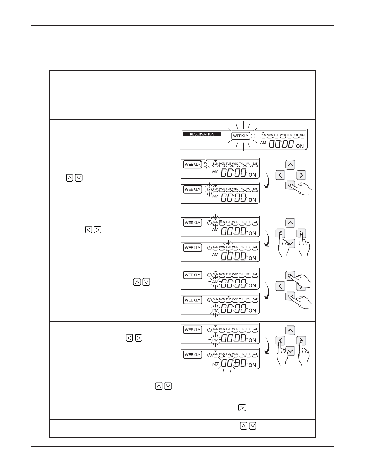
6.8 Weekly Program
You can set the daily reservation in weekly unit.
Weekly reservation keeps operating until before you cancel it once you setup
Part 2 Functions & Controls
Please move to reservation setup mode by pressing reservation button.
1
❈ You can setup two weekly reservations for one day, and up to fourteen
reservations for a week.
For example, to setup (Tuesday morning 11:30 turned on ~ afternoon 12:30
turned off), you setup in order below.
Please move to 'weekly' by
2
repeatedly pressing reservation
button. 'Weekly' blinks at this time.
Please select weekly reservation or
3
weekly reservation ¡ by using
button.
❈ You can setup two reservations,
weekly reservation 1 and weekly
reservation 2, for a day.
Please move to 'date' setup part by
4
using button. If 'date'
indication blinks, please setup date.
You can setup date from Monday to
Sunday.
Please move to 'AM/PM' setup part
5
of turning on by using button.
Please move to 'hour' setup part of
6
turning on by using button.
- It is the part to setup the time at
which air-conditioner is turned on.
Please change time by using button.
7
- You can setup hour 0~12.
Please move to 'minute' setup part of turning on by using button.
8
If 'minute' indication blinks, please setup 'minute' by using button
9
 Loading...