

Page 1

OWNER’S MANUAL
Video Conference Monitor
Please read this manual carefully before operating
your set and retain it for future reference.
MODEL
AVS2400
P/NO : COV30805901 1101(V1.5)
Page 2
Safety Information
2
1
1
Safety Information
Safety Information
CAUTION
RISK OF ELECTRIC SHOCK
DO NOT OPEN
CAUTION: TO REDUCE THE RISK OF ELECTRIC SHOCK
DO NOT REMOVE COVER (OR BACK)
NO USER-SERVICEABLE PARTS INSIDE
REFER SERVICING TO QUALIFIED SERVICE PERSONNEL.
• A suitable conduit for entries, knock-outs or glands shall
be provided in the cable entries of this product in the end
user.
• Caution: Danger of explosion if battery is incorrectly
replaced. Replace only with the same or equivalent type
recommended by the manufacturer. Dispose of used
batteries according to the manufacturer’s instructions.
• Holes in metal, through which insulated wires pass, shall
have smooth well rounded surfaces or shall be provided
with brushings.
This lightning ash with arrowhead
symbol within an equilateral triangle
is intended to alert the user to the
presence of uninsulated dangerous
voltage within the product’s enclosure
that may be of sucient magnitude
to constitute a risk of electric shock to
persons.
The exclamation point within an
equilateral triangle is intended to
alert the user to the presence of
important operating and maintenance
(servicing) instructions in the literature
accompanying the product.
FCC WARNING: This equipment may generate or use
radio frequency energy. Changes or modications to this
equipment may cause harmful interference unless the
modications are expressly approved in the instruction
manual. The user could lose the authority to operate this
equipment if an unauthorized change or modication is
made.
This Class A digital apparatus complies with Canadian
ICES-003.
Cet appareil numérique de la classe A est conforme à la
norme NMB-003 du Canada.
Warning: Do not install this equipment in a conned space
such as a bookcase or similar unit.
Warning: Wiring methods shall be in accordance with the
National Electric Code, ANSI/NFPA 70.
Warning: This is a class A product. In a domestic environment
this product may cause radio interference in which case the
user may be required to take adequate measures.
Warning: To reduce the risk of re or electric shock, do not
expose this product to rain or moisture.
Caution: This installation should be made by a qualied
service person and should conform to all local codes.
Caution: To avoid electrical shock, do not open the cabinet.
Refer servicing to qualied personnel only.
Caution: The apparatus should not be exposed to water
(dripping or splashing) and no objects lled with liquids, such
as vases, should be placed on the apparatus.
REGULATORY INFORMATION: FCC Part 15
This equipment has been tested and found to comply
with the limits for a Class A digital device, pursuant to Part
15 of the FCC Rules. These limits are designed to provide
reasonable protection against harmful interference when the
equipment is operated in a commercial environment.
This equipment generates, uses, and can radiate radio
frequency energy and, if not installed and used in accordance
with the instruction manual, may cause harmful interference
to radio communications.
Operation of this equipment in a residential area is likely to
cause harmful interference in which case the user will be
required to correct the interference at his own expense.
To disconnect power from mains, pull out the mains cord
plug. When installing the product, ensure that the plug is
easily accessible.
Page 3
Safety Information
3
LG Electronics hereby declares that this/
these product(s) is/are in compliance with
the essential requirements and other relevant
provisions of Directive 2004/108/EC, 2006/95/
EC, and 2009/125/EC.
European representative :
LG Electronics Service Europe B.V. Veluwezoom
15, 1327
AE Almere. The Netherlands
(Tel : +31-(0)36-547-8888)
Disposal of your old appliance
1. When this crossed-out wheeled bin symbol is
attached to a product it means the product is
covered by the European Directive 2002/96/
EC.
2. All electrical and electronic products should
be disposed of separately from the municipal
waste stream via designated collection
facilities appointed by the government or the
local authorities.
3. The correct disposal of your old appliance
will help prevent potential negative
consequences for the environment and
human health.
4. For more detailed information about disposal
of your old appliance, please contact your
city oce, waste disposal service or the shop
where you purchased the product.
EEE Compliance with Directive. (for Turkey only)
IMPORTANT SAFETY INSTRUCTIONS
1. Read these instructions.
2. Keep these instructions.
3. Heed all warnings.
4. Follow all instructions.
5. Do not use this apparatus near water.
6. Clean only with dry cloth.
7. Do not block any ventilation openings. Install in
accordance with the manufacturer’s instructions.
8. Do not install near any heat sources such as radiators,
heat registers, stoves, or other apparatus (including
ampliers) that produce heat.
9. Do not defeat the safety purpose of the polarized or
grounding-type plug. A polarized plug has two blades
with one wider than the other. A grounding type plug
has two blades and a third grounding prong. The wide
blade or the third prong are provided for your safety. If
the provided plug does not t into your outlet, consult an
electrician for replacement of the obsolete outlet.
10. Protect the power cord from being walked on or pinched
particularly at plugs, convenience receptacles, and the
point where they exit from the apparatus.
11. Only use attachments/accessories specied by the
manufacturer.
12. Use only with the cart, stand, tripod, bracket, or table
specied by the manufacturer, or sold with the apparatus.
When a cart is used, use caution when moving the cart/
apparatus combination to avoid injury from tip-over.
1
Safety Information
Safety way to remove the battery or the battery from the
equipment:
Remove the old battery or battery pack, follow the steps in
reverse order than the assembly. To prevent contamination
of the environment and bring on possible threat to human
and animal health, the old battery or the battery put it in the
appropriate container at designated collection points. Do
not dispose of batteries or battery together with other waste.
It is recommended that you use local, free reimbursement
systems batteries and accumulators. The battery shall not be
exposed to excessive heat such as sunshine, re or the lile.
• Lamp(s) Contain Mercury, Dispose Properly.
• The lamps in this product contain mercury. Please
dispose according to state, local or federal law.
• This product contains a lamp(s) which contains
mercury; dispose according to local state, or federal
laws.
13. Unplug this apparatus during lightning storms or when
unused for long periods of time.
14. Refer all servicing to qualied service personnel. Servicing
is required when the apparatus has been damaged in
any way, such as power-supply cord or plug is damaged,
liquid has been spilled or objects have fallen into the
apparatus, the apparatus has been exposed to rain
or moisture, does not operate normally, or has been
dropped.
Page 4

Safety Information
4
On Safety
This unit has been engineered and manufactured to ensure your personal safety, however improper use may result in potential
1
electrical shock or re hazards. In order to allow the proper operation of all safeguards incorporated in this display, observe the
Safety Information
following basic rules for its installation, use, and servicing.
Use only the power cord supplied with the unit. In case you use another power cord, make sure that it is certied by the
applicable national standards if not being provided by the supplier. If the power cable is faulty in any way, please contact the
manufacturer or the nearest authorized repair service provider for a replacement. The power supply cord is used as the main
disconnection device. Ensure that the socket-outlet is easily accessible after installation. Operate the display only from a power
source indicated in the specications of this manual or listed on the display. If you are not sure what type of power supply you
have in your home, consult with your dealer. Overloaded AC outlets and extension cords are dangerous. So they are frayed
power cords and broken plugs. They may result in a shock or re hazard. Call your service technician for replacement. As long as
this unit is connected to the AC wall outlet, it is not disconnected from the AC power source even if the unit is turned o.
Do not Open the Display:
• There are no user serviceable components inside.
• There are Dangerous High Voltages inside, even when the power is OFF.
• Contact your dealer if the display is not operating properly.
To Avoid Personal Injury:
• Do not place the display on a sloping shelf unless properly secured.
• Use only a stand recommended by the manufacturer.
• Do not drop an object on or apply impact to the product. Do not throw any toys or objects on the product screen. It can
cause injury to human, problem to product and damage the display.
To Prevent Fire or Hazards:
• Always turn the display OFF if you leave the room for more than a short period of time. Never leave the display ON when
leaving the house.
• Keep children from dropping or pushing objects into the display’s cabinet openings. Some internal parts carry hazardous
voltages.
• Do not add accessories that have not been designed for this display.
• When the display is to be left unattended for an extended period of time, unplug it from the wall outlet.
• In the presence of thunder and lightning, never touch the power cord and signal cable because it can be very dangerous. It
can cause electric shock.
On Installation
Do not allow anything to rest upon or roll over the power cord, and do not place the display where the power cord is subject to
damage.
Do not use this display near water such as near a bathtub, washbowl, kitchen sink, laundry tub, in a wet basement, or near a
swimming pool.
Displays are provided with ventilation openings in the cabinet to allow the release of heat generated during operation. If these
openings are blocked, built-up heat can cause failures which may result in a re hazard. Therefore, NEVER:
• Block the bottom ventilation slots by placing the display on a bed, sofa, rug, etc.
• Place the display in a built-in enclosure unless proper ventilation is provided.
• Cover the openings with cloth or other material.
• Place the display near or over a radiator or heat source.
Do not rub or strike the Active Matrix LCD with anything hard as this may scratch, mar, or damage the Active Matrix LCD
permanently.
Page 5

Safety Information
Do not press the LCD screen with your nger for a long time as this may cause some afterimages.
Some dot defects may appear as Red, Green or Blue spots on the screen. However, this will have no impact or eect on the
display performance.
If possible, use the recommended resolution to obtain the best image quality for your LCD display. If used under any mode
except the recommended resolution, some scaled or processed images may appear on the screen. However, this is characteristic
of the xed-resolution LCD panel.
Leaving a xed image on the screen for a long time may cause damage to the screen and cause image burn-in. Make sure you
use a screen saver on the product. Burn-in and related problems are not covered by the warranty on this product.
Do not shock or scratch the front and sides of the screen with metallic objects. Otherwise, it may cause damage to the screen.
Make sure the panel faces forward and hold it with both hands to move. If you drop the product, the damaged product can
cause electric shock or re. Contact an authorized service center for repair.
Avoid high temperatures and humidity.
On Cleaning
• Unplug the display before cleaning the face of the display screen.
• Use a slightly damp (not wet) cloth. Do not use an aerosol directly on the display screen because over-spraying may cause
electric shock.
• When cleaning the product, unplug the power cord and scrub gently with a soft cloth to prevent scratching. Do not clean
with a wet cloth or spray water or other liquids directly onto the product. An electric shock may occur. (Do not use chemicals
such as benzene, paint thinners or alcohol)
• Spray water onto a soft cloth 2 to 4 times, and use it to clean the front frame; wipe in one direction only. Too much moisture
may cause staining.
5
1
Safety Information
On Repacking
Do not throw away the carton and packing materials. They make an ideal container in which to transport the unit. When
shipping the unit to another location, repack it in its original material.
On Disposal
• Do not dispose of this product with general household waste.
• Disposal of this product must be carried out in accordance to the regulations of your local authority.
Lifting and moving the VCS
When moving or lifting the VCS, read the following to prevent the VCS from being scratched or damaged and for safe
transportation regardless of its type and size.
• Moving the VCS in the box is recommended.
• Before moving or lifting the VCS, disconnect the power cord and all cables.
• When holding the VCS, the screen should face away from you to prevent the screen from being scratched.
• Hold the top and bottom of the VCS frame rmly.
• When transporting the VCS, do not expose the VCS to jolts or excessive vibration.
• When transporting the VCS, keep the VCS upright. Never turn the VCS on its side or tilt towards the left or right.
• When moving the VCS, do not carry it by the camera.
Page 6

Contents
6
Contents
13 Attaching the stand
14 Disassembling the stand
14 Using the Kensington security system
(optional)
15 Connecting to a PC
1
Safety Information
3 IMPORTANT SAFETY INSTRUCTIONS
4 On Safety
4 On Installation
5 On Cleaning
5 On Repacking
5 On Disposal
5 Lifting and moving the VCS
17 Connecting Network
17 Connecting Power
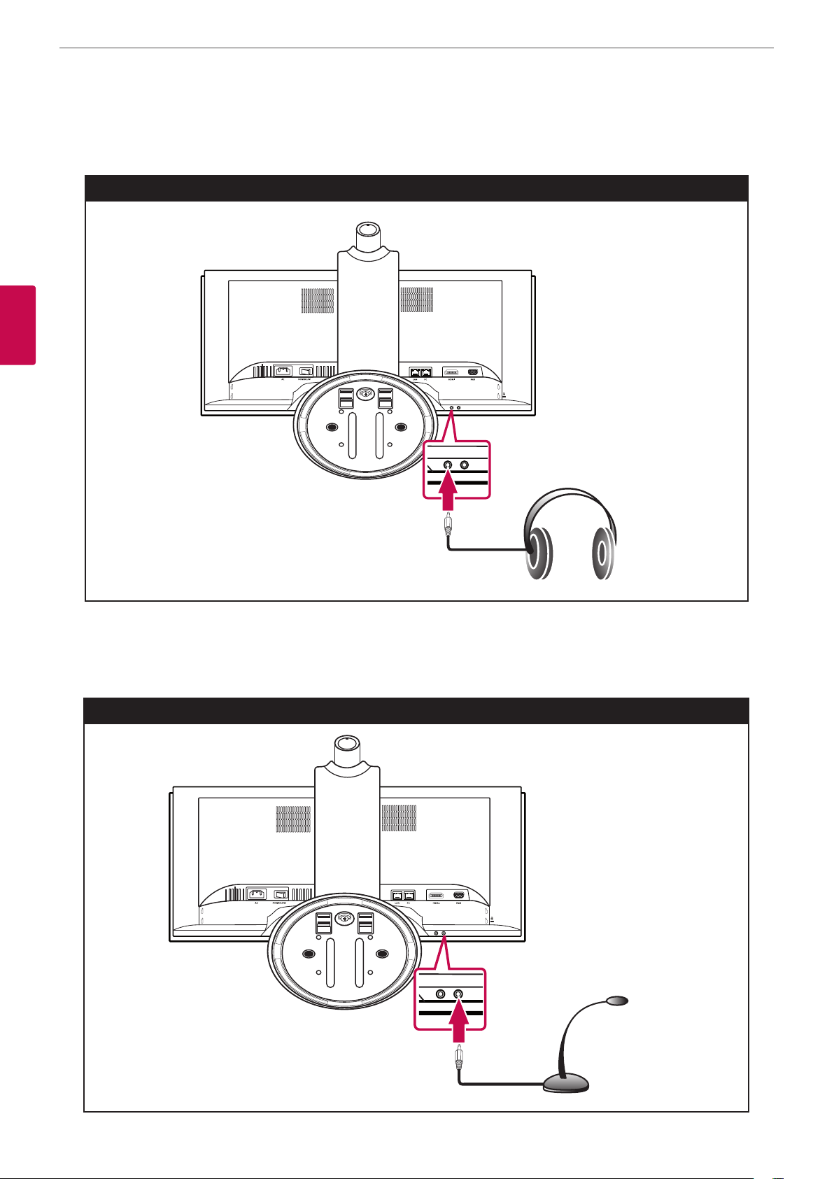
18 Connecting Headphones
18 Connecting a Microphone
19 Attaching the back cover
19 Adjusting the angle of the Monitor and
camera
20 Initial settings for VCS
24 Main screen overview
26 Accessing the System Menu
27 User Preferences setup
28 Administrator Preferences
2
Preparation
8 Introduction
8 Features
9 Unpacking
10 Overview
10 Front of the VCS
11 Rear of the VCS
12 Remote Control
12 Battery Installation
3
Installation
28 Accessing Administrative Features
30 Configuring Call Preferences
31 Configuring Security Preferences
33 Viewing Recent Configuration Changes
33 Configuring Audio Behaviors
35 Configuring Network Usage
39 Disabling Access to the Local Directory
41 Enabling Telepresence
41 Configuring Communications Preferences
44 Configuring Appearance Preferences
45 Configuring Video Behaviors
46 Configuring System Settings
49 Using Diagnostics Preferences and Tools
51 Do Not Disturb
13 Connections
52 Exclusive Web Administration Features
52 Using Advanced Directory Features
Page 7

Contents
7
52 Saving and Restoring a System
Configuration
53 Copying Screen Text to the Clipboard
53 Downloading Call History
53 Upgrading System Software
54 Managing Calls from the Web Administration
Interface
54 Upgrading your System Software
54 Troubleshooting Upgrade Failures
55 Upgrade Error Codes
4
Operation
56 Near End Video Quality
63 Locking and Unlocking Entries in the
REDIAL List
63 Removing an Entry from the REDIAL List
63 Adding a REDIAL List Entry to the
Directory
64 Managing the Directory
64 Adding an Entry to the Local Directory
64 Copying an Entry from the Corporate to
the Local Directory
64 Removing an Entry from the Local
Directory
65 Editing an Entry in the Local Directory
65 Adding an Entry to the Meetings Directory
5
Monitor settings
1
2
3
4
5
56 Placing a Call
56 Placing a Call from the REDIAL List
57 Placing a Call from the Directory
57 Manually Dialing a Number from the Main
Screen
58 Manually Dialing a Voice Number
58 Answering or Rejecting a Call
59 Using System Do Not Disturb
59 Managing a Call
59 Call Status
59 Caller ID
60 Hiding or Showing User Interface
Elements
60 Managing Audio
66 Customizing OSD settings
66 Navigation button overview
66 MENU settings
68 MODE settings
6
Troubleshooting
7
Appendix
71 Specifications
74 WARRANTY CARD
6
7
60 Managing PIP
60 Managing Video Layout
62 Viewing Call Statistics
62 Ending a Call
63 Managing the REDIAL List
Page 8
Preparation
8
2
Preparation
2
Preparation
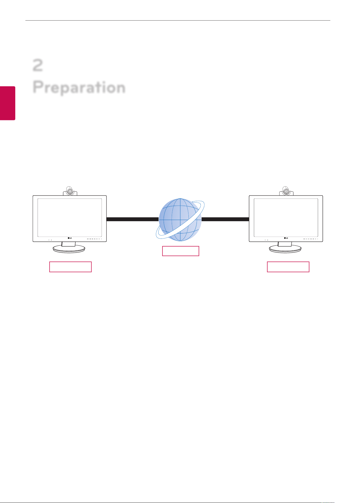
Introduction
The LG video conference monitor is designed to be used for video conferencing, enabling people in a dierent space such as a
conference room or oce to have a meeting (by seeing, listening and speaking to each other on a screen.)
Through this device, not only can executives or managers have a meeting and communicate with customers, subcontractors
and coworkers in real time but you can also make a decision and interchange information immediately, saving you time and
money.
VCS VCS
Features
• IP based 1- to-1 Video conferencing system
• H.323, SIP communications
• 60.96 cm 1 920x1 080p Full HD wide LCD monitor
• 1 280x 720p, 30 fps HD Camera
• H.261 / 3 / 4 & H.239 (receive) video standard
• G.711 / 2 / 2.1C & G.728 / 9 audio standard
• AMC (Adaptive Motion Control)
• Echo cancellation for echo-free calls
Network
Page 9
Preparation
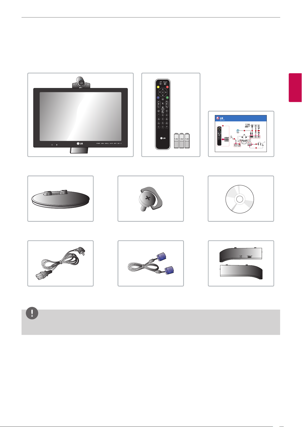
Unpacking
Check your product box for the following items. If there are any missing accessories, contact the local dealer where you
purchased your product. The illustrations in this manual may dier from the actual product and item.
9
2
Preparation
VCS Body
Video Conference Monitor
Quick Setup Guide
8
6
Remote control and batteries Quick Setup Guide
Stand locking screwStand base
CD (Owner’s Manual)
AVS2400
1-1
1
23
Optional
7
4
5
P/NO : COV30806001
Power cord D-sub 15 pin signal cable
Back cover
NOTE
Illustrations of the product can be unlike actual product. Some items of product can be changed depending on the
circumstances.
Page 10
Preparation
10
Overview
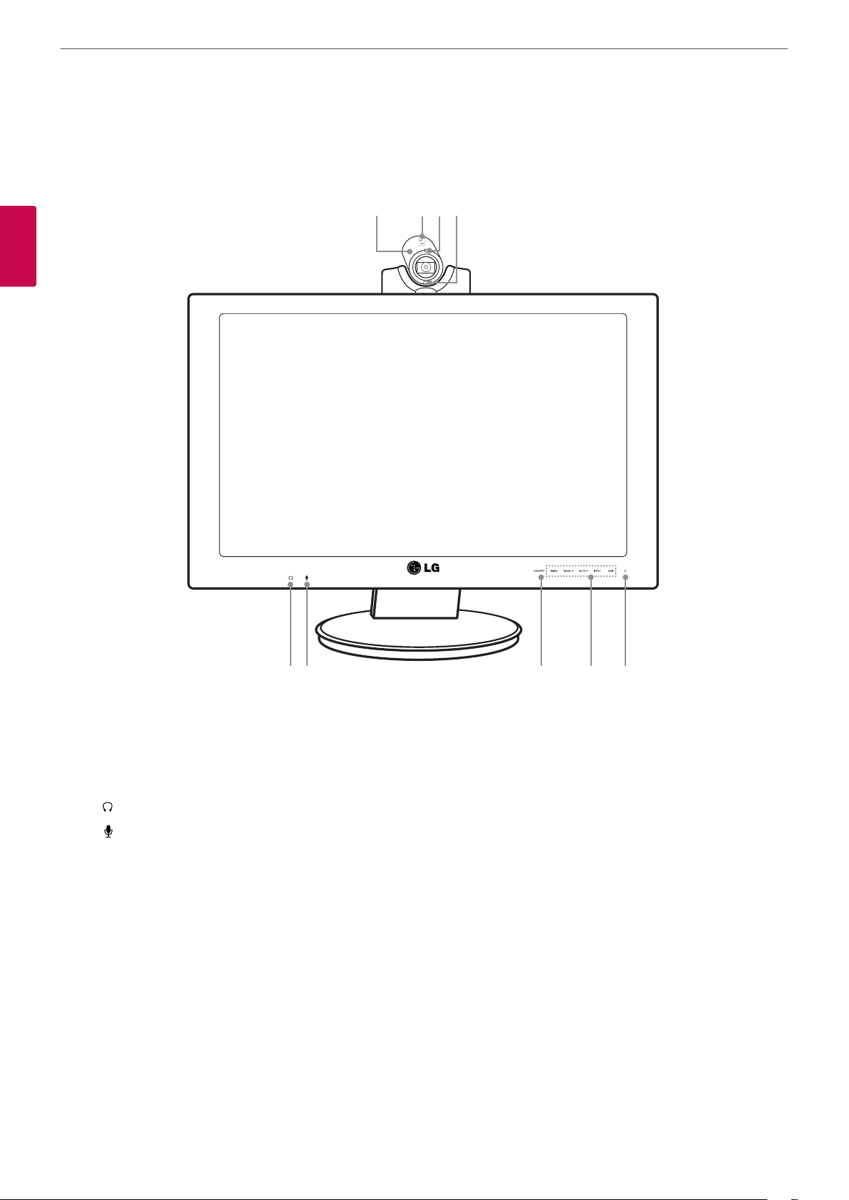
Front of the VCS
a b c d
2
Preparation
e f g h i
High Denition Camera.
a
Internal microphone.
b
VCS condition Indicator: Lights when the VCS turns on.
c
Remote Sensor: Point the remote control here.
d
: Logo for Headset jack.
e
: Logo for Microphone jack.
f
VCS/MNT: Changes the input source between VCS and Monitor.
g
OSD menu control buttons.
h
• MENU: Displays the MENU setup window or moves to the previous menu.
• MODE w: Displays the MODE setup window or navigates the menu items.
• AUTO s: When adjusting your display settings, always press the AUTO button before entering the On Screen Display.
(Only Analog Mode). This will automatically adjust your display image to the ideal settings for the current screen
resolution size (display mode).
• INPUT: When two input signals are connected, you can select the input signal (D-SUB/HDMI/VCS) you want.
• EXIT: Exit the OSD menu.
Page 11
Preparation
NOTE
OSD lock / unlock function
You can lock the current control settings, so that they cannot be inadvertently changed.
1. Press and hold the MENU button for several seconds. The message “OSD LOCKED” should appear.
2. You can unlock the OSD controls at any time by holding the MENU button for several seconds. The message “OSD
UNLOCKED” should appear.
Monitor power button: Turns the monitor on and o. The camera and system power are not turned o by the monitor
i
power button. You can turn the camera and system power o by using the Main power switch.
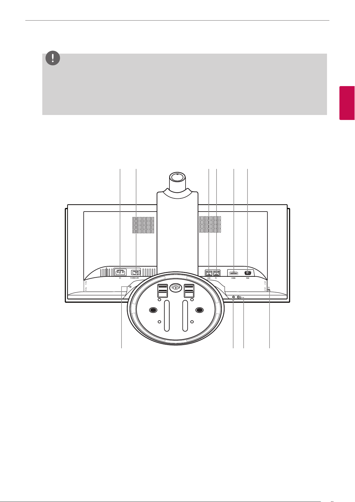
Rear of the VCS
j k l m n o
11
2
Preparation
Power cord Inlet (AC IN): Connects the power plug.
j
Main power switch: Turns the unit on and o. You must turn the unit on using the main power switch after
k
connecting the power cable. You can use this button to reset the system.
LAN port: Connects the LAN cable for this system.
l
PC (LAN) port: Connects the LAN cable between the VCS and your PC.
m
HDMI port: Connects the VCS and the PC with a HDMI cable.
n
D-SUB port: Connects the VCS and the PC with the D-SUB cable.
o
Speaker set: Two speakers are built-in.
p
Microphone jack: Connects an external microphone.
q
Headphone jack: Connects an external speaker device.
r
LOCK: Connects the Kensington security system cable between the VCS and a large object such as a desk.
s
p q r s
Page 12
Preparation
12
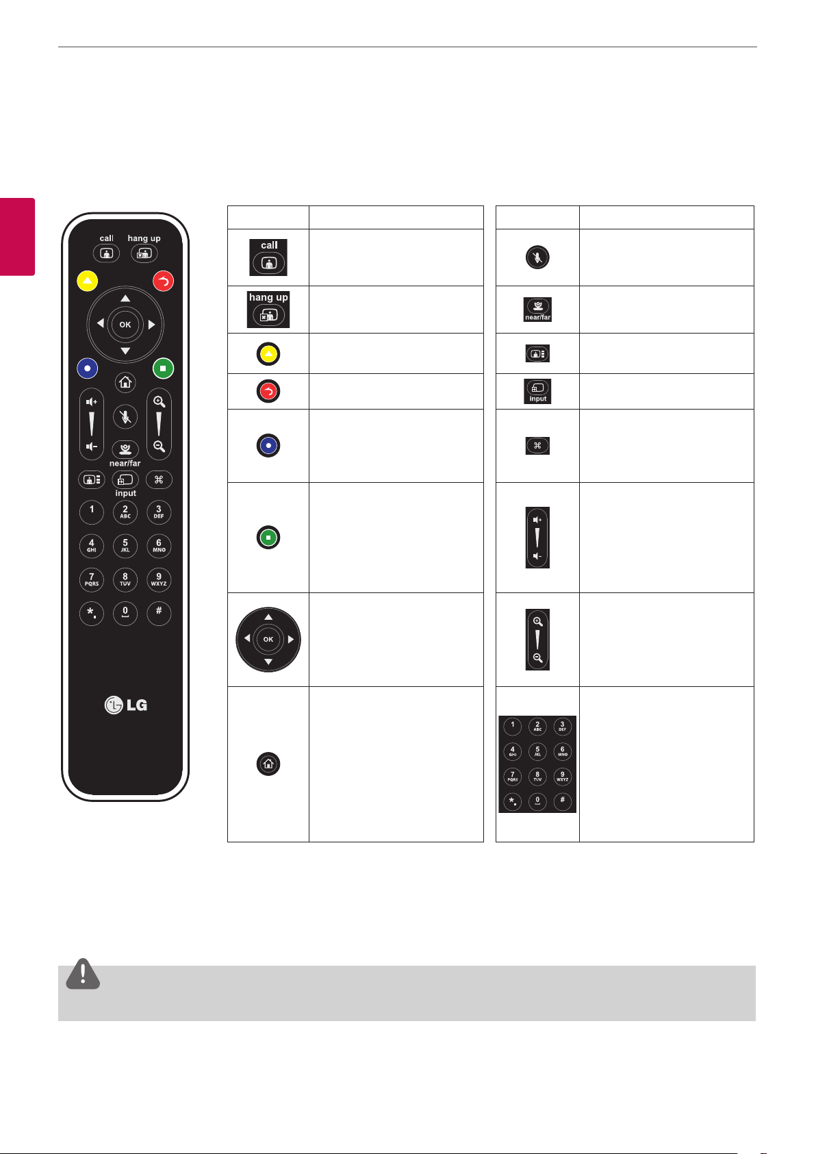
Remote Control
This remote control provides wireless control of Video conference system functions and enables you to navigate the user
interface, place and receive calls. (You cannot control the monitor using this remote control)
Button Description Button Description
2
Preparation
Use this button when the
system receives a call or to
manually make a call.
Use this button when you
want to hang up.
Displays the directory menu. Use this button to change the
Return to the previous mode. This button is not available.
Displays the system menu. Use this button to set the far
• Move to the next page on
the current screen.
• This button behaves as
backspace when you
enter text or numbers
manually.
•
wsad
between the menu
options.
• OK: Conrms menu
selections.
: Select or move
Use this button to mute the
microphones of the near end
system.
Use this button to select the
near or far end camera.
screen layout.
end camera preset or display
the submenu of the directory
menu.
Use this button to adjust the
volume in a call.
Use this button to adjust the
zoom of the far-end camera
with zoom function.
Use this button to return to
the main screen.
Use these buttons to input
text or numbers.
Battery Installation
Open the battery cover, replace batteries (1.5 V AAA) matching 3 and 2 ends to the label inside the compartment and then
close the battery cover.
CAUTION
Do not mix old and new batteries, this may damage the remote control.
Page 13
Installation
3
Installation
Connections
CAUTION
Before setting up the monitor, ensure that the power to the monitor, the computer system and other attached devices are
turned o.
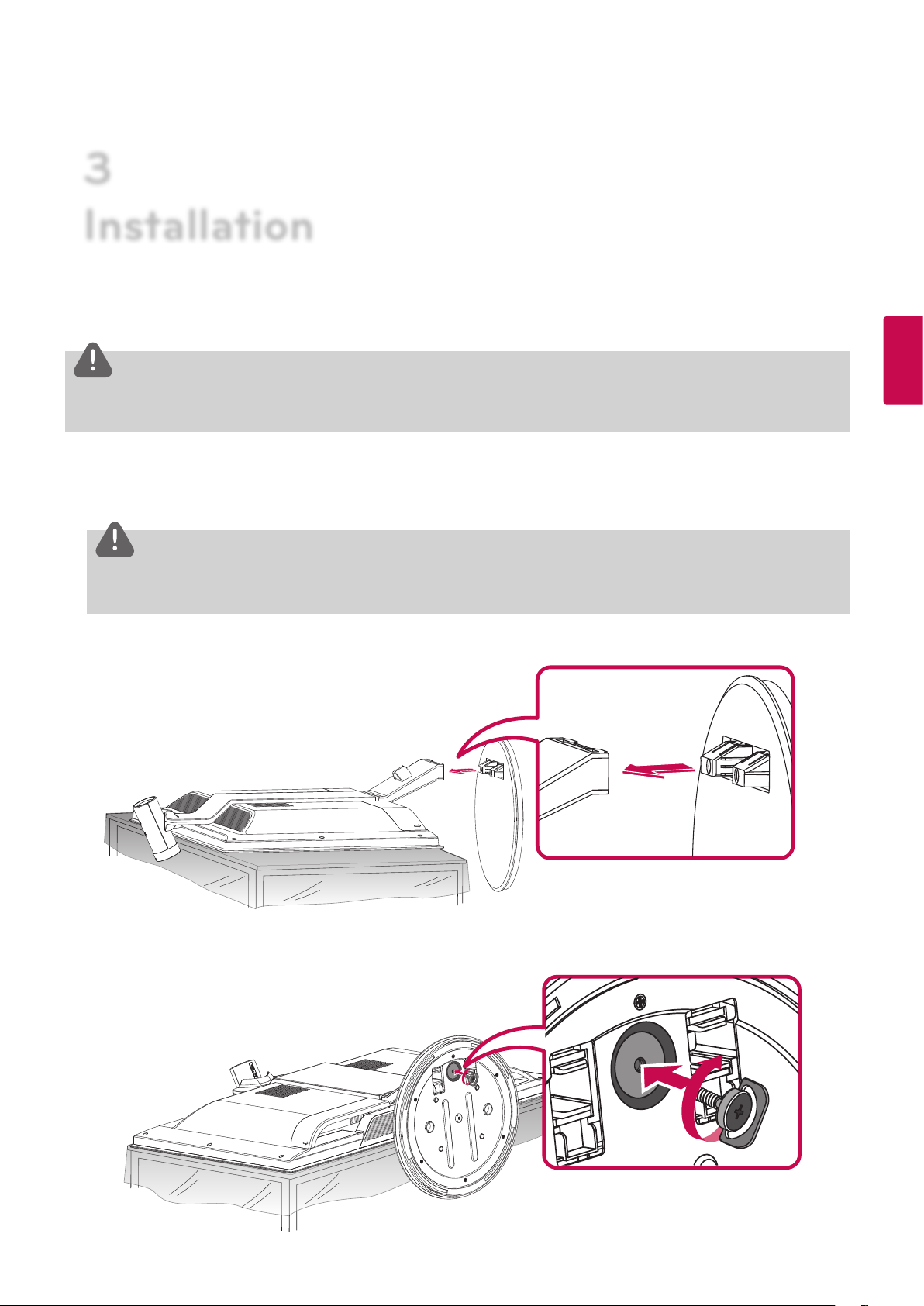
Attaching the stand
13
3
Installation
1. Lay the VCS with the screen side down on a at surface.
CAUTION
Lay a foam mat or soft protective cloth on the surface and then lay the VCS carefully to prevent the camera from breaking
and protect the screen from damage.
2. Make sure to assemble the front and rear side of the stand. Push it into the VCS body as shown in the following illustration.
3. Turn the Stand locking screw clockwise to tighten. Do not over tighten.
Page 14
Installation
14
CAUTION
Do not attempt to tighten a screw too tightly. If you do, the thread groove or the grip of the locking nut may become
damaged.
Tighten a screw to x a monitor on the stand base so that it does not separate. This may cause an accident.
4. Once assembled, lift the monitor up carefully and face the front side.
CAUTION
Do not make the monitor stand by holding the camera. It can be broken and damaged.
3
Installation
Disassembling the stand
1. Place the VCS with its front facing downward on a soft cloth.
2. Turn the Stand locking screw counterclockwise to disconnect the stand base from the monitor.
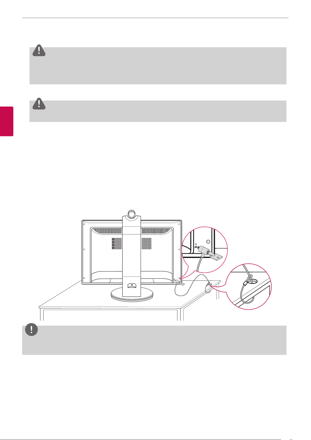
Using the Kensington security system (optional)
The Kensington security system connector is located at the rear of the VCS. Connect the Kensington security system cable
between the VCS and a table.
NOTE
The Kensington security system is optional. You can obtain additional accessories from your local dealer.
Page 15
Installation
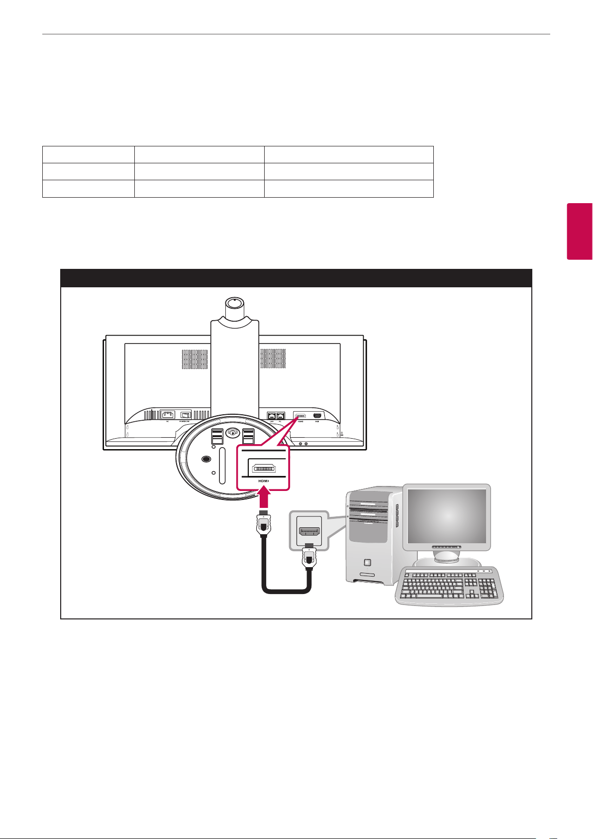
Connecting to a PC
This VCS supports the Plug & Play feature and has built-in speakers.
Connect the VCS according to your PC. Refer to the following table.
HDMI D-SUB
Video O (Digital) O (Analog)
Audio O (Digital) X
HDMI connection
Transmits the digital video and audio signals from your PC to the Monitor set. Connect the PC and the Monitor set with the
HDMI cable as shown in the following illustrations.
When using the HDMI cable
15
3
Installation
Page 16
Installation
16
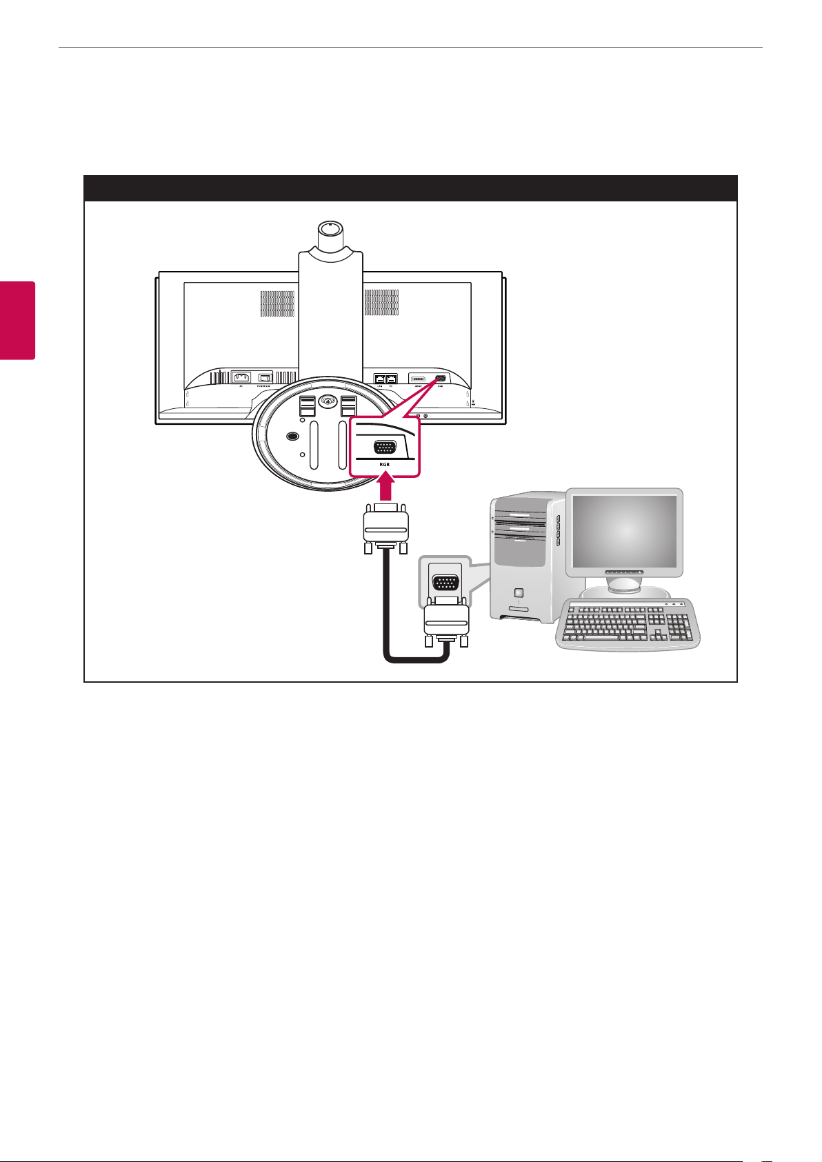
D-SUB connection
Transmits the analog video signal from your PC to the Monitor set. Connect the PC and the Monitor set with the supplied D-sub
15 pin signal cable as shown in the following illustrations.
When using the D-SUB cable
3
Installation
Page 17
Installation
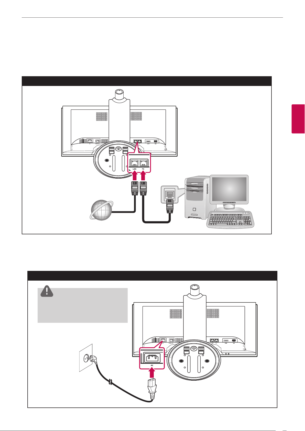
Connecting Network
Connect the LAN port on the rear of the VCS to your network using the optional LAN cable. This device has two LAN ports. One
of them is for network and the other is for PC. If you connect the PC as shown below, you can use the network on the PC and
VCS at the same time.
Network connection
17
3
Installation
Broadband
Service
Connecting Power
Connect the power cable as shown in the following illustrations.
Power connection
CAUTION
You must turn the unit on using the
main power switch after connecting
the power cable.
Page 18
Installation
18
Connecting Headphones
Connect a headphone cable to the headphone jack at the bottom of the VCS.
Headphone connection
3
Installation
Connecting a Microphone
Connect a microphone to the microphone jack at the bottom of the VCS. To use the external microphone, you have to set the
[Active Microphone] option to “Microphone In” on the Administrator Preferences : Audio setup menu.
Microphone connection
Page 19
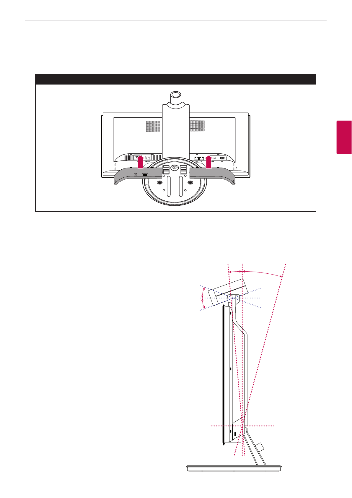
Attaching the back cover
Attach the back covers when all of the connections are made as shown in the following illustrations.
Attaching the back cover
Installation
19
3
Installation
Adjusting the angle of the Monitor and camera
After installation, adjust the angle of the Monitor and camera in various ways for maximum comfort.
It is recommended that the tilt angle of the monitor and camera should not exceed the degrees below in order to maintain an
ergonomic and comfortable viewing position.
• Camera tilt range : -20° (down) to 20° (up)
• Monitor tilt range: -5° (forward) to 15°
(backward)
20°
-20°
-5°
15°
Page 20
Installation
20
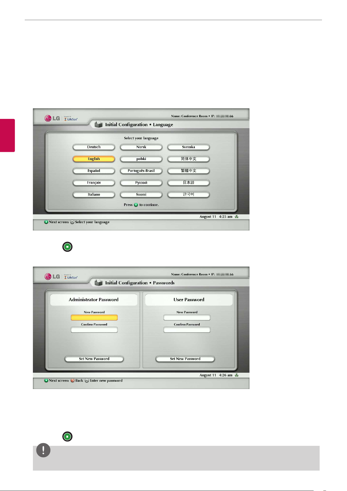
Initial settings for VCS
When you access the VCS for the rst time, the Initial setting screen appears. Select a language and customize the basic settings.
1. Turn on the unit. System booting will commence. The logo image will be displayed during the system booting.
2. When the booting is complete the initial conguration menu will be displayed.
3. Set the language.
3
Installation
3-1. Select your language using the
3-2. Press button to continue. The password setting menu is displayed.
4. Set the Administrator or User password.
4-1. Press OK button on the [New Password] option. Enter the password using number buttons and press OK button.
4-2. Press OK button on the [Conrm Password] option. Enter the password again using number buttons and press OK
button.
4-3. Select [Set New Password] option and press OK button. The conrmation message window is displayed. Press OK
button again.
wsad
buttons and press OK button.
4-4. Press button to continue. The System identication setting menu is displayed.
NOTE
The default administrator password is “1 2 3 4”.
Page 21
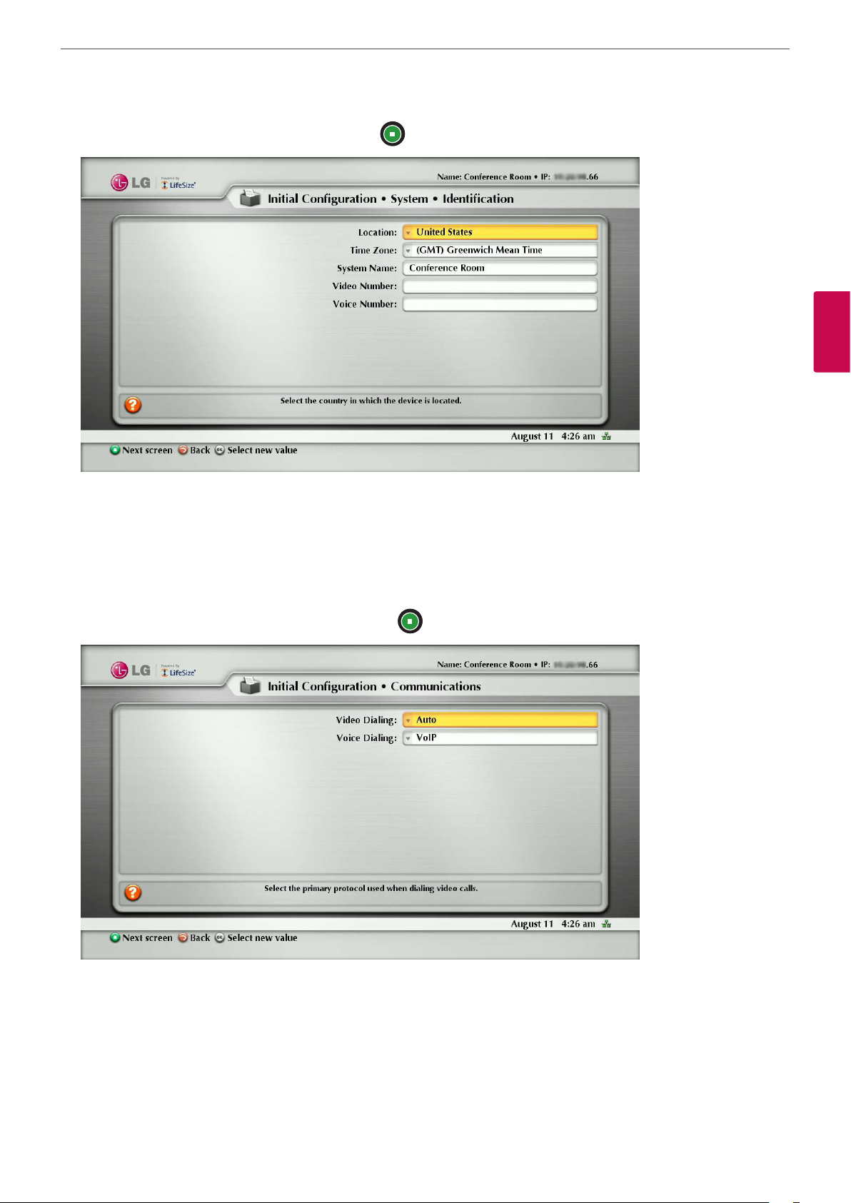
5. Set the options of the Identication menu and press button.
Installation
21
3
Installation
• Location: Select the country where the device is located.
• Time Zone: Select the city corresponding to the time zone of the system location.
• System Name: Enter a descriptive name for the system. The system name is used for far end system.
• Video Number: Enter the video number of the system.
• Voice Number: Enter the voice number of the system.
6. Set the options of the Communication menu and press button.
• Video Dialing: Select the primary protocol you want to use when dialing video calls.
• Voice Dialing: Select the protocol you want to use when dialing voice calls.
Page 22
Installation
22
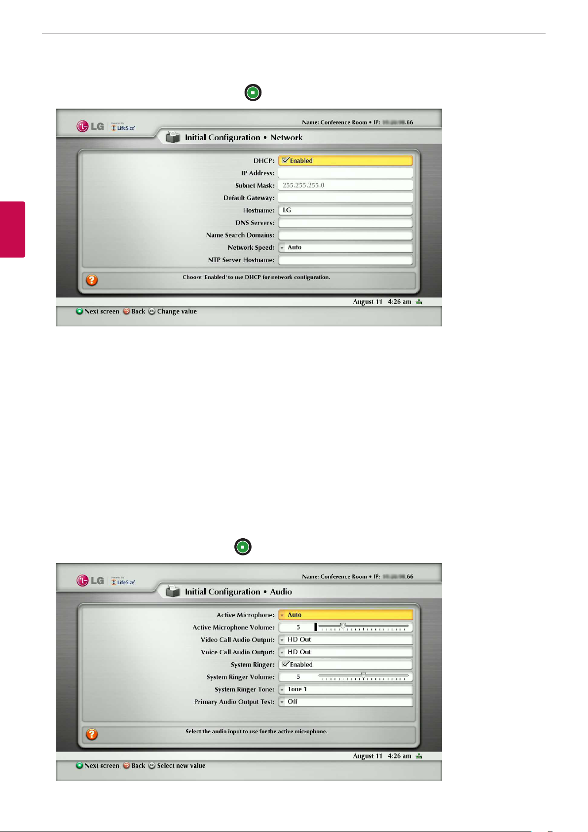
7. Set the options of the Network menu and press button.
3
Installation
• DHCP: Select this option when a DHCP server is installed on the network to allow IP address assignment. With this setting,
the IP address is assigned automatically. If you select this option, IP address, Subnet Mask and Default Gateway options
cannot be set.
• IP Address: Enter the static IP address of the device.
• Subnet Mask: Enter the subnet mask IP address.
• Default Gateway: Enter the default gateway IP address.
• Hostname: Enter the hostname.
• DNS Servers: Enter the IP address to congure as DNS servers. (The IP addresses of the DNS server are separated by
blanks.)
• Name Search Domains: Enter the domain names to search when resolving hostnames.
• Network Speed: Select the speed and duplex capability of your network. (If the quality of the video and audio call is low,
change the network speed to low value.)
• NTP Server Hostname: Enter the hostname or IP address of the NTP server.
8. Set the options of the Audio menu and press button.
Page 23
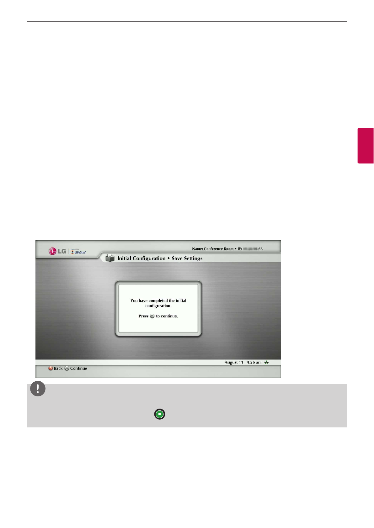
• Active Microphone: Select the audio input to use for the active microphone.
- Auto: Select this option to set the active microphone automatically. If you select this option, basically the unit selects
the built-in microphone of the camera.
- Microphone In: Set this option to use the connected external microphone.
- Camera 1: Set this option to use the built-in microphone of the camera.
• Active Microphone Volume: Select the volume level for the active microphone.
• Video Call Audio Output: Select the location for audio output during video calls.
- HD Out: Set this option to use the built-in speakers for audio output during video calls.
- Line Out: Set this option to use the connected external headphone for audio output during video calls.
• Voice Call Audio Output: Select the location for audio output during voice calls.
- HD Out: Set this option to use the built-in speakers for audio output during voice calls.
- Line Out: Set this option to use the connected external headphone for audio output during voice calls.
• System Ringer: Choose ‘Enabled’ to enable the system ringer for the system.
• System Ringer Volume: Select the volume level for the system ringer.
• System Ringer Tone: Select the tone for the system ringer.
Installation
23
3
Installation
• Primary Audio Output Test: Select the test to perform. During testing you should hear test tone. If you want to stop the
test, set it to o.
9. If you complete the initial conguration, press OK button to save the settings.
VCS main menu will be displayed.
NOTE
• Additionally, refer to the on-screen instructions for each option setting.
• If you want to skip some option settings, press
button.
Page 24

Installation
24
Main screen overview
a b c d
3
Installation
e f g
Video Call button: Use this button to dial numbers manually.
a
Local Video Window: Displays the current input video of the local camera.
b
The redial list: You can make a call by selecting a number from a list of recently dialed numbers.
c
System information: Displays the system information such as the system name and video number. This information is
d
hidden during a call.
Navigation bar: The navigation bar is a grey bar that appears below the system status bar. The navigation
e
bar contains icons that correspond to buttons on the remote control. It also contains text that describes
the action of a button performance. The icons and text change depending on how you use the system.
NOTE
Pressing and holding any button except the OK button on the remote control may cause the command associated
with the button to repeat.
Voice Call button: Use this button to dial numbers manually.
f
System status bar: The system status bar indicates system and network status, including the number of voice and video
g
calls, the time and date or the duration of a call when a call is in progress. The following table identies the icons that can
appear in the system status bar.
Page 25

Icon Description
Indicates a video call in progress. An orange circle appears to the right of the video icon to
indicate a video call in progress.
Indicates a voice call in progress. An orange circle appears to the right of the voice icon to
indicate a voice call in progress.
Indicates that the communication subsystem is initializing. If this icon reappears after the system
has booted, a problem has occurred and rebooting the system is necessary.
Indicates that the system is initializing. When the system is initializing, functionality on the main
screen is disabled and no entries appear in the REDIAL list. This icon also appears when a new
device is connected to the system after the system boots and disappears when the device is
ready. If the icon persists, a problem has occurred and rebooting the system is necessary.
Indicates that the system does not have an active microphone. Contact your administrator.
Installation
25
3
Installation
Network Status
System
Overheating
SIP server
registration
status
Identies the network status, as follows:
• - The indicator turns green when the network is connected.
NOTE
If the LAN cable is disconnected during operation, the indicator stays green. It will change
to the red indicator after rebooting the system.
• - The indicator turns yellow when the network is progressing.
• - The indicator turns red, if the network is disconnected and then the system is
rebooted.
This yellow indicator warns you when the system temperature is above normal operating
temperature. The system adjusts fan speed automatically to cool itself.
This red indicator warns that the system is overheated and approaching the maximum allowed
operating temperature and will automatically reboot after reaching it.
When SIP is congured as the protocol for placing calls, this indicator identies the registration
status of the system with the SIP server as follows:
in progress (yellow indicator)
registration failed (red indicator)
Contact your administrator.
Indicates the registration status of the system with a H.323 gatekeeper as follows:
H.323
gatekeeper
registration
in progress (yellow indicator)
registration failed (red indicator)
status
Contact your administrator.
NOTE
When your system is idle, a screen saver appears on the display, or the screen is black. An incoming call or pressing any
button on the remote control automatically invokes the system.
Page 26

Installation
26
Accessing the System Menu
1. On the main screen, press the button to access the System Menu.
The system information and the conguration menu are displayed. The system information pages show the conguration
and status information about your system. Use the and buttons on the remote control to navigate the pages.
3
Installation
2. Select a system menu and set the options. Refer to the next pages for more details.
3. Press the or button to exit the system menu.
Page 27
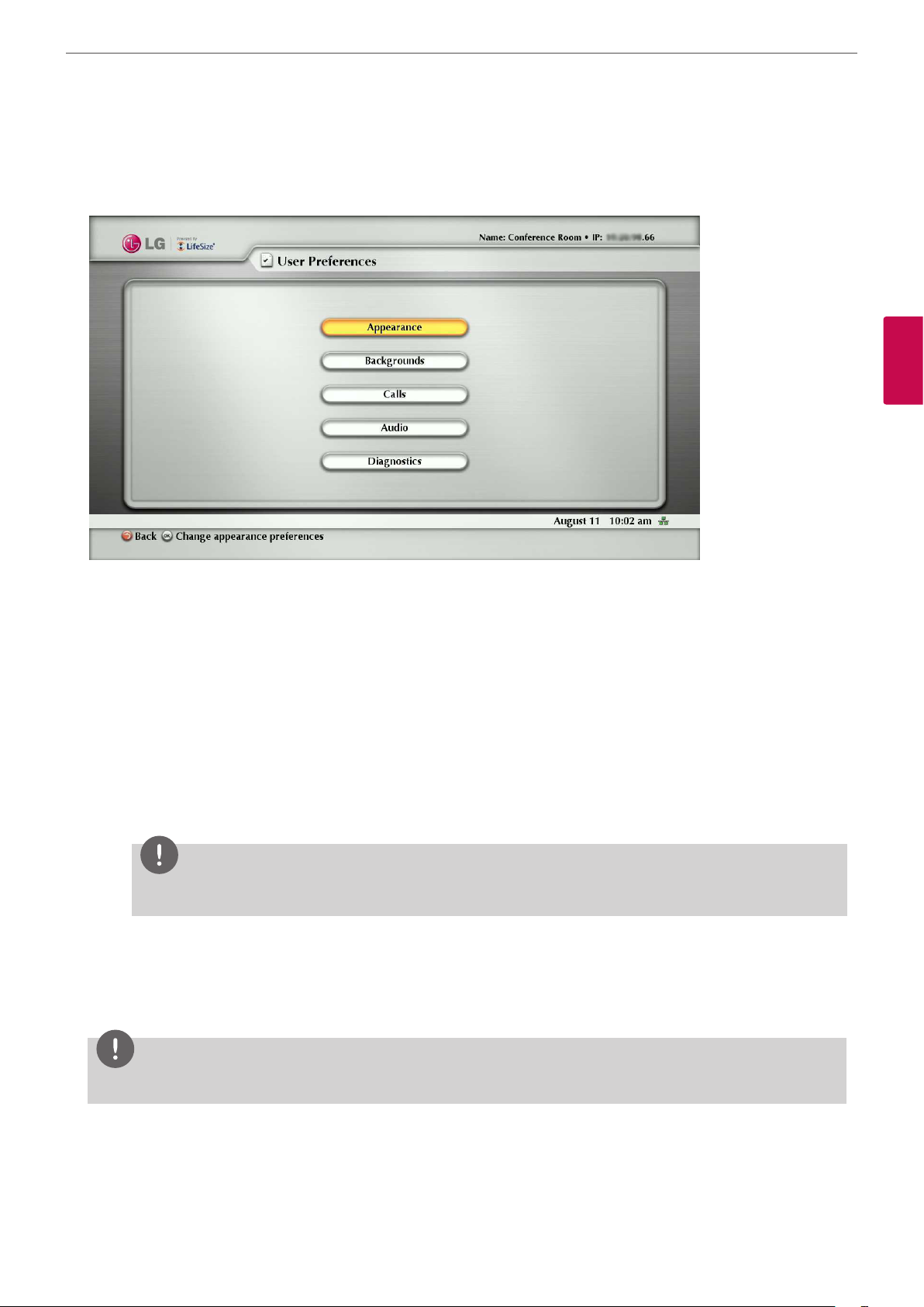
User Preferences setup
Access User Preferences from which you can do the following:
Installation
27
3
Installation
• Appearance: Change the appearance of the user interface, including the language, screen saver and screen saver
timeout, system sleep timeout, and the duration of time that the user interface appears after a call connects.
• Backgrounds: Change the background image or color.
• Calls: Choose the method the system uses for answering calls. For more information, refer to “Answering or Rejecting a
Call” on page 58.
• Audio: Adjust settings for audio input and output devices connected to the system. For more information, refer to
“Managing Audio” on page 60.
• Diagnostics: Access diagnostic tools to adjust camera settings and reboot the system. You can use the camera diagnostic
preferences to adjust camera brightness and white balance and correct for some types of icker that may appear in the
video.
- Adjusting Camera Brightness: Camera brightness refers to the amount of light received through the lens of the
camera. You can improve dim scenes by manually adjusting the camera brightness.
NOTE
Camera has auto-exposure algorithm. If the exposure is already high, brightness will not change.
- Adjusting Camera White Balance: Adjust the white balance when video color appears to be unbalanced. White
balance is aected by the type of light source.
- Adjusting the Camera Anti-Flicker Preference: Lights powered by a 50 Hz power source can produce a icker that the
camera captures and transmits to the system. If you are using lights powered by a 50 Hz power source and observe a
icker in the video displayed in your system, select the 60 Hz option. The default option is Auto.
NOTE
Administrator can set the password not to access these preferences.
Page 28

Installation
28
Administrator Preferences
Administrator Preferences is protected by password and contains preferences for administrators only.
3
Installation
Accessing Administrative Features
You can manage your video communications system using the remote control or remotely using a web browser, telnet session,
or secure shell (ssh) session.
Administration Using the Remote Control
To access administrator preferences for conguring the system using the remote control, follow these steps:
1. From the main screen of the user interface, press the button on the remote control to access the System Menu.
2. Select Administrator Preferences and press OK.
3. Enter the administrator password and press OK.
NOTE
The default administrator password is “1 2 3 4”. To change the administrator password, refer to “Changing the Administrator
Password” on page 32. If you enter an incorrect password, press the
Attempt Failed message.
Administration from a Web Browser
To congure your system from a web browser, you must have Adobe Flash Player installed and congured on your web
browser. You can download the Flash Player from www.adobe.com. Refer to the LifeSize Passport Release Notes for the
supported Flash Player version. Release Notes are available from the Support page of www.lifesize.com.
button on the remote control to clear the Login
By default, remote access to your system through a web browser is enabled. To disable remote access through a web
browser, select Disabled for the HTTP preference in Administrator Preferences : Security : General.
Page 29

Installation
To access the web administration interface, follow these steps.
1. Open a web browser and enter the IP address of your system in the web address eld. The IP address of the system
appears at the top of the main screen in the user interface. A login screen appears.
NOTE
This is a secure Internet connection, and you may receive an unknown certicate warning.
2. In the login screen, do the following:
2-1. Choose the language in which to display the interface.
2-2. Enter the administrator password.
29
2-3. Click Submit.
3. When you are nished administering the system, click the Log out button at the bottom of the screen, and then close
your web browser.
Administration from an SSH Session
You can manage your system from an SSH session. By default, remote access through an SSH session is enabled. Log in
through an SSH session and enter commands using the automation command line interface to remotely manage your
system. For more information, refer to the “LifeSize Passport Automation Command Line Interface” manual on the Support
page of www.lifesize.com. To disable remote access through an ssh session, select Disabled for the SSH preference in
Administrator Preferences : Security :General.
Administration from a Telnet Session
You can manage your system from a telnet session. By default, remote access through a telnet session is disabled. LG
recommends that you use the web administration interface or an ssh session to manage your system remotely. To enable
remote access through a telnet session, select Enabled for the Telnet preference in Administrator Preferences : Security :
General. Use the automation command line interface to manage the system through a telnet session. For more information,
refer to the “LifeSize Passport Automation Command Line Interface” manual on the Support page of www.lifesize.com.
Administration Using LifeSize MIBs
This system is SNMP-enabled devices that support SNMPv3.
With a LifeSize custom MIB compiled on your SNMP manager and an SNMP user congured on your system, you can monitor
and congure your system from your SNMP manager console.
3
Installation
To use SNMP features, select Enabled for the SNMP preference in Administrator Preferences : Security : General. LifeSize
MIBs are available for download as ASCII text les from the Support page of www.lifesize.com.
For more information about using LifeSize custom MIBs and conguring your system for use with LifeSize custom MIBs, refer
to the Support page of www.lifesize.com.
Page 30

Installation
30
Configuring Call Preferences
All users can set auto answer options for calls and specify the maximum number of entries to appear in the Redial list.
Refer to “Placing a Call” on page 56 for more information.
Administrators can congure the maximum call time and bandwidth in Administrator Preferences : Calls.
3
Installation
Managing Bandwidth
You can specify the maximum bandwidth that an outgoing or incoming call uses by setting the Outgoing Maximum
Bandwidth and Incoming Maximum Bandwidth preferences in Administrator Preferences : Calls.
The value that you choose for the Outgoing Maximum Bandwidth becomes the maximum value that users can choose in
the user interface when placing a call by dialing a number manually or when specifying a bandwidth in a directory entry.
If a user species Auto for the bandwidth when placing a call, the maximum outgoing bandwidth becomes the starting
point for negotiating bandwidth when the call connects.
If you choose Auto as the value for the Outgoing Maximum Bandwidth and Incoming Maximum Bandwidth preferences and
the user chooses Auto for the bandwidth when placing the call, the system places the call at 1152 kb/s.
The Auto Bandwidth preference addresses how the system responds to packet loss during a call.
When set to Enabled, the system attempts to use the best available bandwidth after the call connects.
Selecting a Maximum Call Time
You can control the amount of time that a call stays connected by selecting an option for the Maximum Call Time preference
in Administrator Preferences : Calls.
Controlling REDIAL List Entries
Users and administrators can control the number of entries that appear in the REDIAL list and how the system answers calls
in User Preferences and Administrator Preferences : Calls.
Refer to “Placing a Call” on page 56 for more information.
Auto Answer Options
You can congure your system to automatically answer incoming calls by setting preferences in User Preferences : Calls or
Administrator Preferences : Calls menu as follows:
• Auto Answer: If it is set to Enabled, the system automatically answers the rst incoming call. If it is set to Disabled (the
default), you must manually answer incoming calls.
If your system is congured for answering calls manually, choose one of the following options when an incoming call
arrives:
Page 31

Installation
- Select Answer and press OK to accept the call.
- Select Ignore and press OK to reject the call.
• Auto Answer Mute: If it is set to Enabled (the default), and the Auto Answer preference is set to Enabled, the system is
muted when a call connects.
• Auto Answer Multiway Call: If it is set to Enabled, the system automatically answers after the rst call is connected. The
Multiway call function is allowed only for audio call.
Admission Control
You can congure your system to automatically reject incoming calls by setting preferences in Administrator Preferences :
Calls menu. If it is set to Enabled, the system automatically rejects the incoming calls if it is under a heavy load.
31
Configuring Security Preferences
You can set preferences in Administrator Preferences : Security to manage the administrator and user passwords and control
remote access to the system through the web, telnet, SNMP and ssh. You can also enable H.235 AES security for calls.
3
Installation
Controlling Remote Administration
By default, remote access to LG video conference system through the web (http), SNMP, and ssh is enabled; remote access
through a telnet session is disabled. To enable or disable remote access through any of these mechanisms, congure
preferences in Administrator Preferences : Security : General.
Enabling H.235 AES Security
This unit supports H.235 128-bit AES security using the Die Hellman key exchange protocol in H.323 and H.460 calls. AES
interoperability is supported with the third party devices identied in the Release Notes on the Support page of www.lifesize.
com.
To enable AES security, you must set the Administrator Preferences : Security : General : H.235 AES Security preference
to either Enabled or Strict. When set to Enabled, calls connect, but are encrypted only if the far end supports AES encryption.
When set to Strict, calls do not connect if the far end does not support AES security. Encrypted calls are indicated by
encryption icons in the caller ID, Call Manager list, and Call Statistics list. Refer to “Caller ID” on page 59 for a description of the
icons.
Page 32

Installation
32
Changing the Administrator Password
You can protect the administrator preferences with a secure password to prevent occasional users from changing them.
To change the administrator password, follow these steps:
1. From the System Menu, access Administrator Preferences : Security : Passwords.
2. Enter a new password in the New Password eld below Administrator Password and press OK.
NOTE
• If you did not change the administrator password during initial conguration, the default password is 1 2 3 4.
• If you forget the administrator password, please contact the authorized service center.
3
Installation
3. Re-enter the new password in the Conrm Password eld and press OK.
4. Select the Set New Password button and press OK.
Setting the User Password
You can set a user password to control access to User Preferences screens.
By default, the user password is not set.
To set the user password, follow these steps:
1. From the System Menu, access Administrator Preferences : Security : Passwords.
2. Enter a new password in the New Password eld below User Password and press OK.
3. Re-enter the new password in the Conrm Password eld and press OK.
4. Select the Set New Password button and press OK.
• If you set a user password, you can also access the User Preferences screens with the administrator password.
• If you forget the user password, please contact the authorized service center.
NOTE
Page 33
Installation
Viewing Recent Configuration Changes
As an aid to troubleshooting issues that you may encounter with your system or to quickly access a preference that has been
recently changed, view the preferences in Administrator Preferences : Recent. Preferences that have dependencies on other
preference settings, such as H.323 and SIP server preferences, may not appear in Recent.
33
3
Installation
NOTE
Upgrading the system software removes all preferences from the Recent screen.
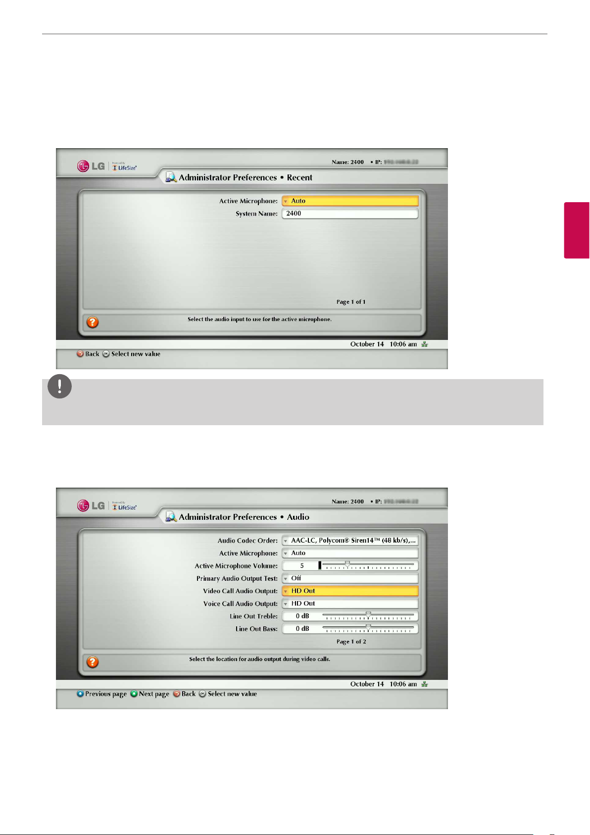
Configuring Audio Behaviors
You can adjust audio behaviors by conguring preferences in Administrator Preferences : Audio.
Configuring Audio Codec Order
To change the order of available audio codecs for the system to use to place calls, select the Audio Codec Order preference,
select a codec, and press the right arrow to move the entry up in the list or press the left arrow to move the entry down in
the list.
Page 34

Installation
34
Selecting the Active Microphone
To select a device to serve as the active microphone, navigate to Administrator Preferences : Audio and select a device in
the Active Microphone preference. The options that are available for the Active Microphone are Auto (default), Microphone
In, and Camera 1.
When the Active Microphone preference is set to Auto (the default), or if the option selected is not connected to the system,
the system automatically attempts to select a Microphone In, and then Camera 1, in that order.
Adjusting the Active Microphone Volume
To control the volume of the active microphone, adjust the Active Microphone Volume preference in User Preferences or
Administrator Preferences : Audio.
Checking Microphone Status
3
Installation
The Active Microphone eld in the System Information page shows which device is functioning as the active microphone.
When the value is None, the No Active Microphone indicator appears in the status bar indicating that no active microphone
is available.
The Microphone In eld appears in the System Information page for systems that have a microphone in connector on the
codec and indicates the connection status of a device for the input (None, Ready, or Error).
Testing Primary Audio Output
You can send audio test tones to speakers that are connected to the system as the primary audio output device.
Navigate to Administrator Preferences : Audio : Primary Audio Output Test.
Select a channel to test, or select Auto. The Auto option cycles through all available channels, playing the test tone for 5
seconds before moving to the next available channel.
To end the test, choose O or navigate to another preference or screen.
Adjusting Audio Levels
In addition to adjusting the audio volume for line in and the active microphone, you can adjust levels associated with the
following preferences:
• Line Out Treble (dB)—Boost the higher frequencies in the sound range for audio output.
• Line Out Bass (dB)—Boost the lower frequencies in the sound range for audio output.
• Ring Tone Volume—Select the volume level of the ring and busy tones.
• DTMF Tone Volume—Select the volume level of the DTMF and key click tones.
• Status Tone Volume—Select the volume level of status tones.
• System Ringer Volume—Select the volume level of the system ringer.
• System Ringer Tone—Select one of ve preset system ringer tones.
Page 35
Installation
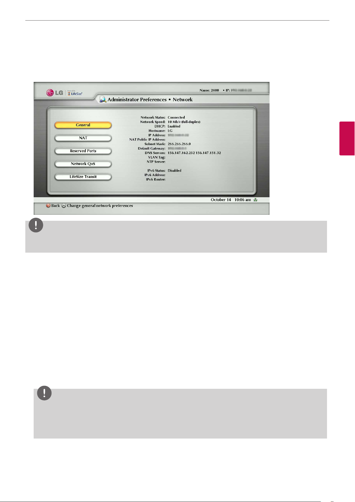
Configuring Network Usage
To congure preferences that aect how your system functions with other servers and devices on your local network, access
Administrator Preferences : Network : General.
35
3
Installation
NOTE
This unit cannot detect a change to its IP address if the change is due to a change in networks from a wiring closet or through
software, such as a change to a router conguration. Reboot the system if the DNS changes.
Specifying a Locally Configured IP Address
Dynamic Host Conguration Protocol (DHCP) is used to dynamically allocate and assign IP addresses. DHCP allows you to
move network devices from one subnet to another without administrative attention. You can choose to enable DHCP if a
DHCP server is present. If you disable DHCP, you must enter an IP address (the locally congured IP address if not assigned by
a DHCP server), subnet mask (used to partition the IP address into a network and host identier), and gateway (IP address of
the default gateway the system uses).
Specifying the Hostname and Domain Name Service (DNS) Servers
You can enter the hostname of the system and the IP addresses to congure DNS servers. You can also enter the domain
names to search when resolving hostnames. Domain Name System (DNS) translates names of network nodes into addresses;
specify this preference to use DNS to resolve the hostnames of devices to IP addresses.
Specifying Network Speed
If you choose an option other than Auto for the Administrator Preferences : Network : General : Network Speed
preference, ensure that it matches the speed and duplex congured on your network switch.
NOTE
If your Ethernet switch is congured for half duplex, you may experience poor quality video when placing calls greater
than 512 Kb/s.
To work around this issue, change your Ethernet switch conguration to a setting other than half duplex when using Auto
for the Network Speed preference.
Page 36

Installation
36
Specifying a VLAN Tag
If you have static virtual local area networks (VLANs) congured in your environment, you can congure your system to apply
a VLAN tag to outgoing packets and only accept incoming tagged packets that have the same VLAN identier.
To enable this feature, navigate to Administrator Preferences : Network : General : VLAN Tag and specify the VLAN
identier of the VLAN to which the system is assigned. The value is a number in the range 1 through 4094.
If you set or modify the VLAN Tag preference, the system reboots when you navigate to another screen.
Specifying an NTP Server
3
Installation
The system date and time that appear in the user interface are automatically set if one of the following conditions exists:
• The Administrator Preferences : Network : General : DHCP preference is set to Enabled, and the DHCP server can pass
an NTP server address to your system.
- or -
• The hostname or IP address of an NTP server is specied in Administrator Preferences : Network : General : NTP
Server Hostname.
NOTE
NOTE
An NTP server address that a DHCP server passes to your system overrides an NTP server hostname or address specied
in the NTP Server Hostname preference.
The System Information page displays the IP address of the NTP server that the system uses.
NOTE
The time zone is not set automatically. If you did not specify the time zone for your system during the initial conguration,
the time that appears in the user interface may not be correct. To specify the time zone manually, refer to “Manually Setting
System Date and Time” on page 47.
Enabling IPv6 Addressing
This system supports dual conguration of IPv4 and IPv6 addressing for the system IP address only. You cannot disable IPv4
addressing on your system. Calls placed with an IPv6 address use the H.323 protocol.
In addition to specifying a local IPv4 IP address (through either DHCP or by manually specifying a static IP address), you can
assign an IPv6 address to your system if you are using IPv6 addressing on your network. Access Administrator Preferences :
Network : General and choose Enabled for the IPv6 preference.
If your IPv6 network sends router advertisements, select Auto for the IPv6 Conguration preference to automatically assign
the IPv6 address to the system. The default option is Auto. If you select Manual for this preference, you can specify a static
IPv6 address for the system in the IPv6 Address preference and the address of your IPv6 router in the IPv6 Router preference.
NOTE
Enabling or disabling IPv6 causes the system to reboot after you exit the preference screen.
The IP address that appears at the top of the main screen in the user interface is the IPv4 address. The IPv6 address of the
system appears in the System Menu on the System Information page.
All other conguration preferences that require an IP address (for example, the NTP and DNS servers, H.323 gatekeeper,
and SIP server) must be IPv4 addresses. You must also use the IPv4 address for your system to access the system remotely
through the web administration interface and an ssh session.
The directory supports IPv6 addresses. Users can also manually dial IPv6 addresses using the Video Call or Voice Call buttons
on the main screen of the user interface and the 0x1a text entry method or screen keyboard. Refer to “Manually Dialing a
Number from the Main Screen” on page 57 for information about changing the text entry mode.
Page 37

Installation
Enabling Network Address Translation (NAT)
Network Address Translation (NAT) enables communication between devices on your LAN that have private IP addresses and
devices that are accessed through a public IP network. Static NAT ensures that the same public IP address always maps to a
system’s private IP address so that data from the public network intended for the private system can be routed to the system
reliably.
If you are using static NAT to associate a public IP address with the private IP address of your system, you must congure your
system to work with your static NAT server. Access Administrator Preferences : Network : NAT and select Enabled for the
Static NAT preference.
Enter the public IP address, hostname, or fully qualied domain name of your system in NAT Public IP Address. The default
entry method for this preference is numeric. To enter text, use the key on the remote control to change the entry
method to text.
37
NOTE
If you are using a static rewall or NAT with xed ports, you cannot register to a public gatekeeper. If you congure H.323
settings and enable H.460 support, the system ignores preferences in Administrator Preferences : Network : NAT.
Refer to “Enabling H.460 Support for H.323 Calls” on page 43 for more information.
The following functions are not supported if your system is accessed from a web browser outside a rewall and static NAT is
enabled:
• System Upgrade
• Directory Import
To work around this issue, execute these functions from within the rewall.
Restricting Reserved Ports
By default, your system communicates through TCP and UDP ports in the range 2 048 to 65 534 for video, voice,
presentations, and camera control. The system uses only a small number of these ports during a call. The exact number
depends on the number of participants in the call, the protocol used, and the number of ports required for the type (video
or voice) of call.
To minimize the number of UDP and TCP ports that are available for communication, you can restrict the range by entering
values in Administrator Preferences : Network : Reserved Ports. LG recommends that the range you choose, if other than
a subset of the default range, begins with a port number greater than 10 000.
3
Installation
NOTE
Changing the TCP range causes an automatic reboot of the system.
An H.323 video call with a presentation requires more ports than other types of calls.
The following tables identify the number of ports required per connection by protocol and the type (video or voice) of call.
Use this information if you need to further restrict the port range.
Page 38

38
3
Installation
Installation
H.323 two-way call required ports:
Call Type Number of Required UDP and TCP Ports
Video
Voice
SIP two-way call required ports:
• 8 UDP ports (6 if presentations are disabled)
• 2 TCP ports
• TCP port 1720
• Each additional video participant added requires 8 UDP ports and 2 TCP ports per H.323
participant.
• 2 UDP ports
• 2 TCP ports
• TCP port 1720
• Each additional audio participant added requires 2 UDP ports and 2 TCP ports.
Call Type Number of Required UDP Ports
• 6 UDP ports
Video
• UDP port 5060
• Each additional video participant added requires 6 UDP ports per SIP participant.
• 2 UDP ports
Voice
• UDP port 5060
• Each additional audio participant added requires 2 UDP ports.
Configuring Quality of Service
You can specify network Quality of Service (QoS) settings in the Administrator Preferences : Network : Network QoS
preferences.
Set these preferences according to the settings used in your network.
NOTE
Network QoS preferences are supported with IPv4 addressing only. If you enable IPv6 addressing on your LifeSize system,
QoS preferences are ignored for IPv6 calls. For more information about IPv6 addressing, refer to “Enabling IPv6 Addressing”
on page 36.
You can specify DiServ (dierentiated services) or IntServ (integrated services) values for audio, video, and data packets.
You can also set the IntServ Type of Service (ToS) preference.
Configuring LifeSize Transit Preferences
If you are using LifeSize Transit with your system, refer to your LifeSize Transit documentation for information about how to
congure preferences in Administrator Preferences : Network : LifeSize Transit.
Page 39
Disabling Access to the Local Directory
By default, users can place calls using entries in the local directory and add, remove, or modify these entries.
For more information, refer to “Placing a Call from the Directory” on page 57.
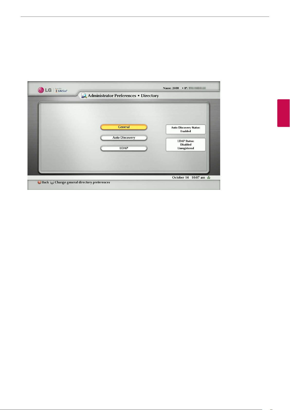
Administrators can disable user access to the local directory by setting Local Directory to Disabled in Administrator
Preferences : Directory : General.
Installation
39
3
Installation
Disabling access to the local directory also disables the following:
• saving entries from the REDIAL list to the local directory
• copying corporate directory entries to the local directory
Administrators maintain access to the local directory on the web administration interface Directory page when the Local
Directory preference is set to Disabled. For more information about managing the local directory from the web administration
interface, refer to “Using Advanced Directory Features” on page 52.
Populating the Corporate Directory
Users can place calls from the directory by selecting a number to dial from a list of stored numbers.
The corporate directory is H.350 compliant and can store up to 1000 entries in both an alphabetical and hierarchical format.
All users can manage entries in the local directory. Only administrators can manage entries in the corporate directory.
You can populate the corporate directory by conguring Auto Discovery preferences or Lightweight Directory Access
Protocol (LDAP) preferences in Administrator Preferences :Directory. By default, auto discovery is enabled and LDAP
is disabled. You can enable only one of these methods. The system automatically disables the other method to prevent
duplicate entries from appearing in the corporate directory. The status of these methods, either enabled or disabled, appears
on the Administrator Preferences : Directory screen. The connection status of the LDAP installation also appears on this
page and on the System Information page.
The values that can appear for the connection status include the following:
Page 40

Installation
40
Reading from an LDAP Server
When you enable and congure LDAP preferences to populate the corporate directory, you specify the hostname, login and
query parameters, and the refresh interval for reading data from a precongured LDAP server. LG recommends that you use
an LDAP server congured with an H.350 compliant schema.
LDAP Connection Status Description
Unregistered LDAP preferences are not congured.
Registered
3
Installation
Unreachable
Unauthorized LDAP preferences are congured, but the username or password is invalid.
Invalid Syntax LDAP preferences are congured, but the base Distinguished Name (DN) is invalid.
Configuring Auto Discovery
Auto discovery enables the systems on your network to pass address information to other systems automatically.
By default, when a system joins a network, it sends a broadcast packet to the local subnet to announce its presence.
Any system on the local subnet that receives the packet and has Auto Discovery set to Enabled replies by sending address
information about itself and a list of IP addresses of other systems that it has discovered.
The system creates an entry in its corporate directory for every system on the local subnet from which it received a response.
It then queries the list of other IP addresses that it received and the IP addresses that are stored in its own Redial list, but
only if those addresses are allowed by the lters that you specify in the Auto Discovery Subnets and Auto Discovery Ignored
Subnets preferences.
LDAP preferences are congured. The last attempt by the system to contact the LDAP
server and receive data was successful.
LDAP preferences are congured, but the LDAP hostname is invalid or the service does
not exist.
Failed LDAP preferences are congured, but an unexpected failure occurred.
By default, the system replies and sends queries to other systems in the local subnet only.
Congure the Auto Discovery Subnets and Auto Discovery Ignored Subnets preferences to enable the system to discover
other systems outside the local subnet and share that information with other systems.
Specify subnet lters (separated by spaces) in the Auto Discovery Subnets preference to identify the subnets to which the
LifeSize system can send queries and replies.
By default, the preference is empty; the system sends queries and replies to other systems on the local subnet only.
To exclude subnets from auto discovery, specify subnet lters in the Auto Discovery Ignored Subnets preference. If a
destination address does not match one of the lters in the Auto Discovery Subnets preference, or if it matches one of the
lters in the Auto Discovery Ignored Subnets preference, then the system does not query or reply to the system at that
address.
For example, you can congure the Auto Discovery Subnets preference to include a large subnet and the Auto Discovery
Ignored Subnets preference to exclude a subset of the subnet. Consider a network that has several subnets with the IP
address 10.* and a slow network connection to devices that have a 10.85.* address. If you enter 10.* in the Auto Discovery
Subnets and 10.85.* in the Auto Discovery Ignored Subnets preference, the system queries and replies to all the systems that
have a 10.* address, except those that have a 10.85.* address.
If you set Auto Discovery to Disabled, the system does not send a broadcast message to the local subnet and cannot
discover or be discovered by other systems.
Page 41

Installation
Enabling Telepresence
You can set the system to telepresence mode in which a conference administrator controls calls from a control panel (such as
LifeSize Control or the Call Manager in the web administration interface).
Enabling telepresence removes the user interface from view. When the system is idle, only the background image appears in the
display. An administrator can access the user interface by pressing OK and entering the administrator password.
During a call, users see the video from the call and the mute indicators. The navigation bar, PIP windows, caller ID information,
and call status messages do not appear on the screen.
Users can invoke the Call Manager dialog and call statistics and choose video inputs with the remote control. The numeric keys
on the remote control play touch tones. Users can change this behavior from the Call Manager.
To enable or disable telepresence and lock or unlock cameras, congure preferences in Administrator Preferences :
Telepresence.
41
3
Installation
Configuring Communications Preferences
You can specify options that control which protocols the system uses during calls by conguring preferences in Administrator
Preferences : Communications.
Page 42

Installation
42
Configuring Dialing Options
You can choose voice and video dialing options during the initial conguration, when performing a system reset, or at any
other time by accessing Administrator Preferences : Communications : General.
Receiving Presentations
This system can receive and initiate presentations during a call through a secondary H.239 media channel.
By default, the presentation function is enabled.
To disable presentations access Administrator Preferences : Communications : General : Presentations.
Consider disabling the presentation function if your system experiences interoperability issues with third party systems that
do not support presentations.
3
Installation
Virtual Link (Data Sharing)
Virtual Link allows this system to share IP-based presentation data during call.
For the most current product information, including a summary of new features, resolved and known issues,
interoperability with third party products, and documentation errata, refer to the Release Notes at www.lifesize.com/
support.
Specifying H.323 Settings
By default, this system supports the H.323 protocol for placing and receiving video and voice calls.
You can disable support for H.323 calls by selecting Disabled for the H.323 preference in Administrator Preferences :
Communications : H.323 when the system is not in a call.
If you choose Disabled for the H.323 preference, the system cannot place or receive calls with the H.323 protocol.
If both H.323 and SIP preferences are set to Disabled, a warning message appears and indicates that video calls cannot be
placed or received with this conguration.
When H.323 is enabled, you can specify an H.323 name or extension to use when placing a call. The H.323 name and
extension identify the device to the gatekeeper. Any registered device can dial another one using this name and extension.
The H.323 Name preference is an optional value that is used when a gatekeeper is congured and requires the system to
register with an H.323 ID. If the gatekeeper administrator assigns an H.323 ID for the system, enter that ID for the H.323
Name preference. The H.323 Extension preference is an optional value that is used when a gatekeeper is congured and
requires the system to register with an E164 number or extension. If the gatekeeper administrator assigns an E164 number or
extension for the system, enter that number for the H.323 Extension preference.
NOTE
NOTE
Set the Gatekeeper ID only if the gatekeeper requires it (for example, congurations with multiple gatekeepers). The
Gatekeeper ID must match the gatekeeper ID congured for the gatekeeper to which the system is registering. Do not
congure this preference if the gatekeeper does not require it, as this may result in failure to register with the gatekeeper.
Set the Gatekeeper Mode preference to Auto if you wish to have the system automatically discover a gatekeeper. You can
also set the Gatekeeper Mode preference to Manual to manually choose a gatekeeper. If set to Manual, specify the IP address
and port for the primary gatekeeper.
When you select the Register button in Administrator Preferences : Communications : H.323, icons appear in the status
bar to indicate the status of the registration process with the H.323 gatekeeper. The yellow H.323 icon appears when
your system is trying to register with the gatekeeper. If the registration fails, the red H.323 icon appears. If the system
is registered to a gatekeeper, the system displays its status.
Conguring a secondary H.323 gatekeeper with the Gatekeeper IP Address 2 and Gatekeeper Port 2 preferences is optional.
Page 43

Enabling H.460 Support for H.323 Calls
This system supports the H.460 protocol for rewall and NAT traversal of H.323 calls. You must have an H.460 server
congured in your environment for this feature to function properly.
NOTE
If you congure H.323 settings and enable H.460 support, the system ignores preferences in Administrator Preferences :
Network : NAT.
To enable H.460 client support on a system, congure the H.323 preferences in Administrator Preferences :
Communications : H.323 with the following exceptions:
• Choose Manual for the Gatekeeper Mode preference.
Installation
43
• For the Gatekeeper IP Address 1 and Gatekeeper Port 1 preferences, enter the IP address and port number of the H.460
server that is congured in your environment.
• Choose Enabled for the H.460 preference.
• Navigate to Register and click OK.
NOTE
If you enable H.460 and specify the IP address and port number of a secondary gatekeeper with the Gatekeeper IP
Address 2 and Gatekeeper Port 2 preferences, the system ignores the secondary gatekeeper.
Configuring SIP Settings
By default, support for Session Initiation Protocol (SIP) is enabled on the system. To congure SIP as the protocol to use for
placing calls, congure SIP preferences in Administrator Preferences : Communications : SIP. You can also disable support
for SIP by choosing Disabled for the SIP preference when the system is not in a call.
If you choose Disabled for the SIP preference, the system cannot place or receive calls with the SIP protocol.
NOTE
If both H.323 and SIP preferences are set to Disabled, a warning message appears and indicates that video calls cannot be
placed or received with this conguration.
For the server, enter the username, SIP server authorization name, and password for the device, if required. The authorization
name and password are the values the system uses for authentication; these values are only required if the registrar or proxy
require authentication.
3
Installation
If you are planning on placing and receiving calls on this system with Microsoft Oce Communications Server,
LG recommends that administrators choose Microsoft OCS for SIP Server Type in Administrator Preferences :
Communications : SIP. The default is Auto. For more information about using Microsoft OCS with LifeSize communications
devices, refer to the technical note on the Support page of www.lifesize.com.
You can change the communication path to use when registering with a SIP Registrar, either directly or through a proxy and
congure proxy settings. SIP devices use register settings to dynamically register their current location.
When you select the Register button and press OK, icons appear in the status bar to indicate the status of the registration
process with the SIP server. The yellow SIP icon appears when your system is trying to register with the SIP server.
If the registration fails, the red SIP icon appears.
You can change the SIP UDP signaling port. You can also enable TCP signaling and change the TCP signaling port. You can
enable Transport Layer Security (TLS) signaling and change the TLS signaling port only if the SIP Registrar preference is set
to Enabled. TCP signaling and TLS signaling are mutually exclusive. Enabling one automatically disables the other. Choosing
Disabled for the SIP Registrar preference automatically disables TLS signaling. If neither TCP nor TLS signaling is enabled, only
UDP signaling is enabled.
Page 44
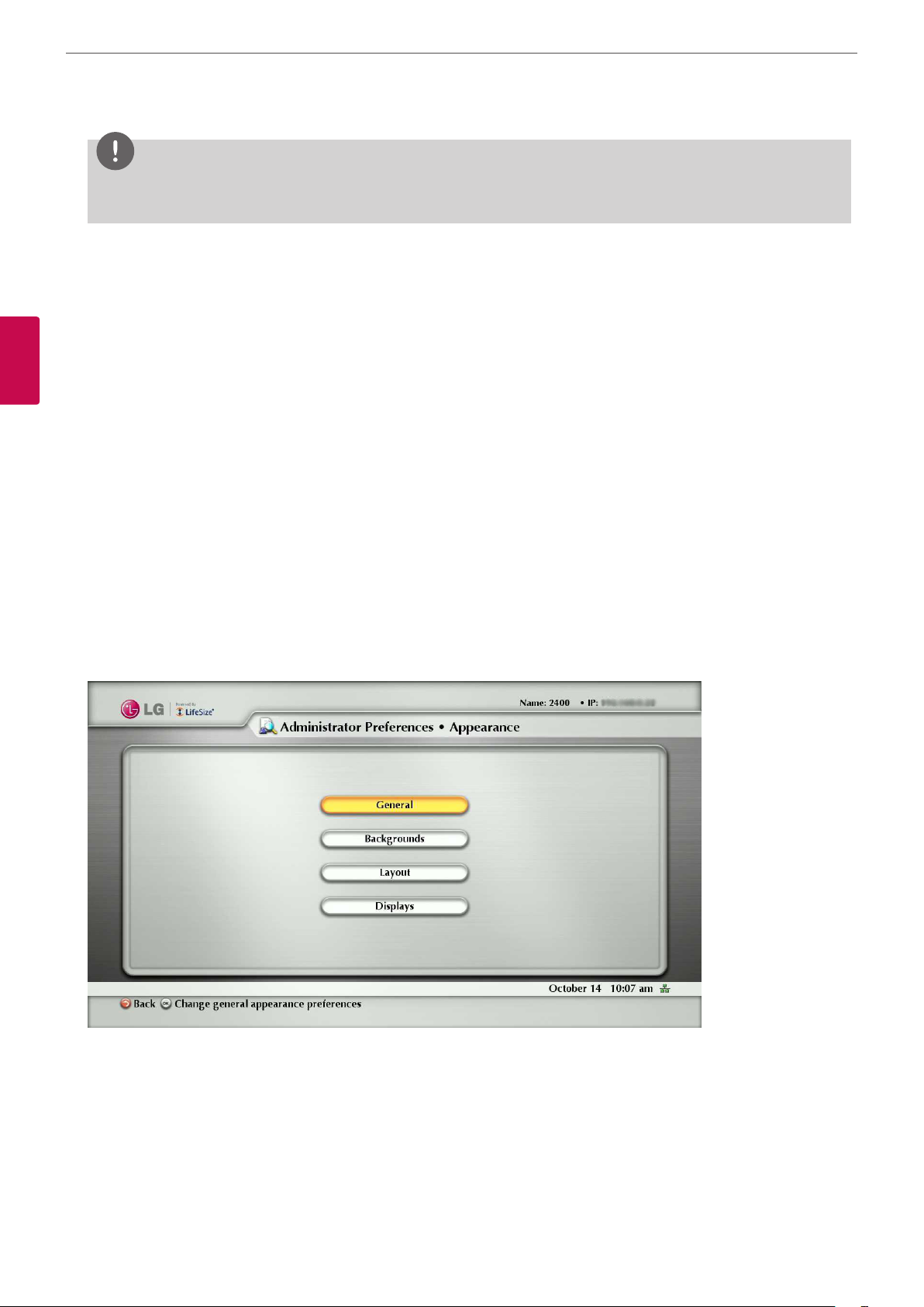
Installation
44
NOTE
The system reboots if you change the UDP signaling port, enable or disable TCP or TLS signaling, or change the TCP or TLS
signaling ports.
If you enable TLS signaling, the system attempts to use Secure Real-time Transport Protocol (SRTP) for media encryption in
SIP calls.
If the far side supports SRTP, the media is encrypted and encryption icons appear in the caller ID, Call Manager list, and Call
Statistics list in the user interface during a call. Refer to “Caller ID” on page 59 for a description of the icons.
If the far end does not support SRTP, the media is not encrypted and call encryption icons do not appear in the user
interface.
3
Installation
Configuring Appearance Preferences
Users can congure preferences in User Preferences : Appearance and Backgrounds that aect the appearance or behavior
of the following:
• screen saver that appears when the system is idle and the screen saver timeout
• system sleep timeout
• timeout interval for the appearance of the user interface after a call connects
• language in which the user interface appears
• background image or color that appears in the user interface
Help text appears at the bottom of the screen to assist users in selecting an option for each preference. Administrators can also
access these preferences in Administrator Preferences : General, Backgrounds, and Layout.
To hide or show LG&LifeSize branding, access Administrator Preferences : Appearance : General : Company Logo.
Choose None to hide the branding. The Default option shows the branding.
Video Layout Preferences
All users can congure the Picture In Picture video layout preference in User Preferences: Appearance. Refer to “Managing
PIP” on page 60 for more information about setting this preference.
Page 45
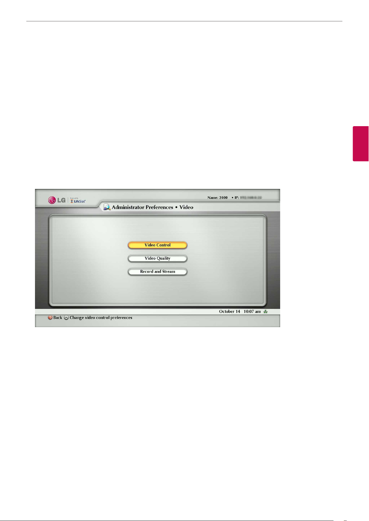
Installation
Configuring Display Preferences
Only administrators can congure preferences that aect display types, resolutions, and energy management options.
Display preferences appear in Administrator Preferences : Appearance : Displays. Typically, you congure display
resolutions when you install your system or change a display and to troubleshoot display issues.
You can set the Display Energy Saver preference to Enabled for connected displays to turn o the signal that the system
sends to the display when the system goes to sleep.
LG recommends that you test this feature for compatibility with your display before using it in your environment. Some
displays may appear black when the signal from the system is no longer received, but not enter an energy saving state. Other
displays may recognize the loss of the signal and show text indicating this state. This may result in the text image burning
into the screen. Some displays may recognize the loss of the signal and power o, but then not wake up when the system
wakes up.
45
Configuring Video Behaviors
Administrators can adjust video behaviors to control cameras and video quality by conguring preferences in Administrator
Preferences : Video.
3
Installation
Controlling the Camera Use by Far End Users
To prevent far end users from controlling your PTZ near end camera, including conguring and controlling camera presets,
choose Disabled for the Administrator Preferences : Video : Video Control : Far Control of Near Camera preference. If
you choose Enabled, you can still prevent far end users from conguring and using near end camera presets by choosing
Disabled for the Far Set of Camera Presets and Far Move to Camera Presets preferences.
Locking the Camera Presets
By default, all users can congure PTZ camera presets. To prevent all users (near and far end) from conguring camera
presets, select Locked for the Administrator Preferences : Video : Video Control : Camera Presets Lock preference.
To prevent only far end users from conguring camera presets, choose Disabled for the Far Control of Near Camera or Far Set
of Camera Presets preferences.
Customizing Input Device Names
You can dene a custom input name by changing the default value for HD Camera 1 Name in Administrator Preferences :
Video : Video Control. Customized names are limited to 16 characters.
The default name is HD Camera 1.
Page 46

Installation
46
Selecting Priority of Quality Metrics for Source Video
You can favor sharpness or motion as a priority for the quality of primary video that the system sends to the far end during a
call.
If you favor sharpness by selecting a smaller number for the Administrator Preferences : Video : Video Quality : Primary
Video Motion preference, in lower bandwidth calls the system sends the primary video at a lower frame rate and a higher
resolution.
The default value (10) favors motion.
Adjusting Video Encoder Quality
You can adjust the quality of the video image sent to the far end during a call by specifying a relative lower or higher
resolution in the Administrator Preferences : Video : Video Quality : Video Encoder Quality preference.
3
Installation
Moving the slider to the right decreases the resolution of the video sent to the far end and improves the quality of the video
image.
Consider using this preference to make minor adjustments to the quality of the video image sent to the far end.
Adjusting the MTU of Video Packets
Video packets that exceed the maximum transmission unit (MTU) size for any router or segment along the network path may
be fragmented or dropped. This results in poor quality video at the receiving device.
You can set the MTU of video packets that your system sends.
The default value is 1 440 bytes. The allowed range is 900 to1 500 bytes.
To set the MTU for video packets, access Administrator Preferences : Video : Video Quality : Video MTU.
Record and Stream
“Record and Stream” in Administrator Preferences : Video is related to use of the LifeSize Video Center which is a network
server that stores and streams video sent by LifeSize video communications systems enable for streaming and recording.
Viewers access these videos and live streams from the server through a browser-based interface on the computers.
For this product information, refer to the Release Notes for LifeSize Video Center at lifesize.com/support.
Configuring System Settings
You can change settings that identify the system to users in the user interface, set the system date and time, check for updates
to license keys, and reset the system to its factory default settings by accessing Administrator Preferences : System.
Page 47

Installation
Rebooting the System automatically
You can reboot the system once a day automatically. If you set the Auto Reboot option to Yes, the reboot occurs at 4:02 am
local time if the system is asleep.
Identifying the System
To change the system name, dialing numbers, and geographic location specied for the system, access Administrator
Preferences : System : Identication.
Manually Setting System Date and Time
You can set the system date and time manually as follows:
1. From the System Menu, access Administrator Preferences : System : Date and Time.
2. Set the time zone.
3. Set the month, day, and year for the date.
4. Set the hour, minute, and second for the time.
5. Select the Set Date and Time button and press OK to save your changes.
47
3
Installation
Updating License Keys (Not available)
A current license key must be installed on the system to perform system software upgrades.
A current license key for upgrades is available when a maintenance agreement for the device is in eect.
The Upgrade License eld in the System Information page shows the expiration date of an upgrade license key installed on
the system.
If the Upgrade License eld is blank or contains a value other than a valid (not expired) date, use the following information to
update or install an upgrade license key on the system.
NOTE
You can install a patch to a software release with an expired license key if the key was current when the software was
released.
The third digit of the three-digit version number of a release identies a patch, for example 4.3.1 is patch 1 to release v4.3.0.
You can check for updates to license keys in either the user interface or the web administration interface if your system has
HTTP access through port 80 to the LifeSize license key server. If your system does not have this access, refer to “Installing a
License Key Manually” on page 48.
Checking for License Key Updates in the User Interface
1. From the main screen press the button on the remote control to access the System Menu.
2. Navigate to Administrator Preferences : System : License Keys.
3. Select Update Keys.
4. Press OK on the remote control.
If the update is successful, Success appears in the Update Key Status box and the current license key and its expiration date
appear in the Upgrade License box. If the update fails, refer to “Troubleshooting a Failed Update” on page 48.
Checking for License Key Updates in the Web Administration Interface
1. Open a web browser and enter the IP address of the system in the web address eld.
NOTE
The IP address of the system appears at the top of the main screen in the user interface.
A login screen appears.
Page 48

48
3
Installation
Installation
NOTE
This is a secure Internet connection, and you may receive an unknown certicate warning.
2. In the login screen, do the following:
2-1. Choose the language in which to display the interface.
2-2. Enter the administrator password.
2-3. Click Submit.
3. Navigate to Preferences : System : License Keys.
4. Click the Update Keys button. If the update is successful, Success appears in the Update Key Status box and the current
license key and its expiration date appear in the Upgrade License box.
5. When you are nished, click the Log out button at the bottom of the screen, and then close your web browser.
Troubleshooting a Failed Update
If an update to a license key fails in the user or web administration interfaces, one of the following messages appears in the
Update Key Status box:
Status Message Description
A current maintenance agreement for the device does not exist. Contact your Authorized
No Contract
Partner to renew your maintenance agreement. The renewal process may require 24 to 48
hours to complete.
The system failed to connect to the LifeSize license key server. The server may be down or your
Service Unavailable
system may not have HTTP access to the server. Contact Technical Services if this condition
persists and you have HTTP access to the server, or install a key manually using the instructions
in “Installing a License Key Manually”.
Invalid Key A license key exists, but is invalid. Contact Technical Services.
Installing a License Key Manually
If you cannot obtain a license key using the license key update feature in the user or web administration interface, you can
install a key manually from the web administration interface by doing the following:
1. Click the Download Software button on the Support page of www.lifesize.com.
2. Enter the serial number of your video communications system and click Submit.
3. Copy the license key from the software download page to your operating system clipboard.
4. Open a separate web browser window and access the web administration interface of your video communications
system.
5. Navigate to Preferences : System : License Keys.
6. In the Enter New Key box, paste the license key that you copied in step 3.
7. Click the Add Key button. The key and its expiration date appear in the Upgrade License box.
NOTE
The Add Key button is available only after you copy a key in the Enter New Key box.
Page 49
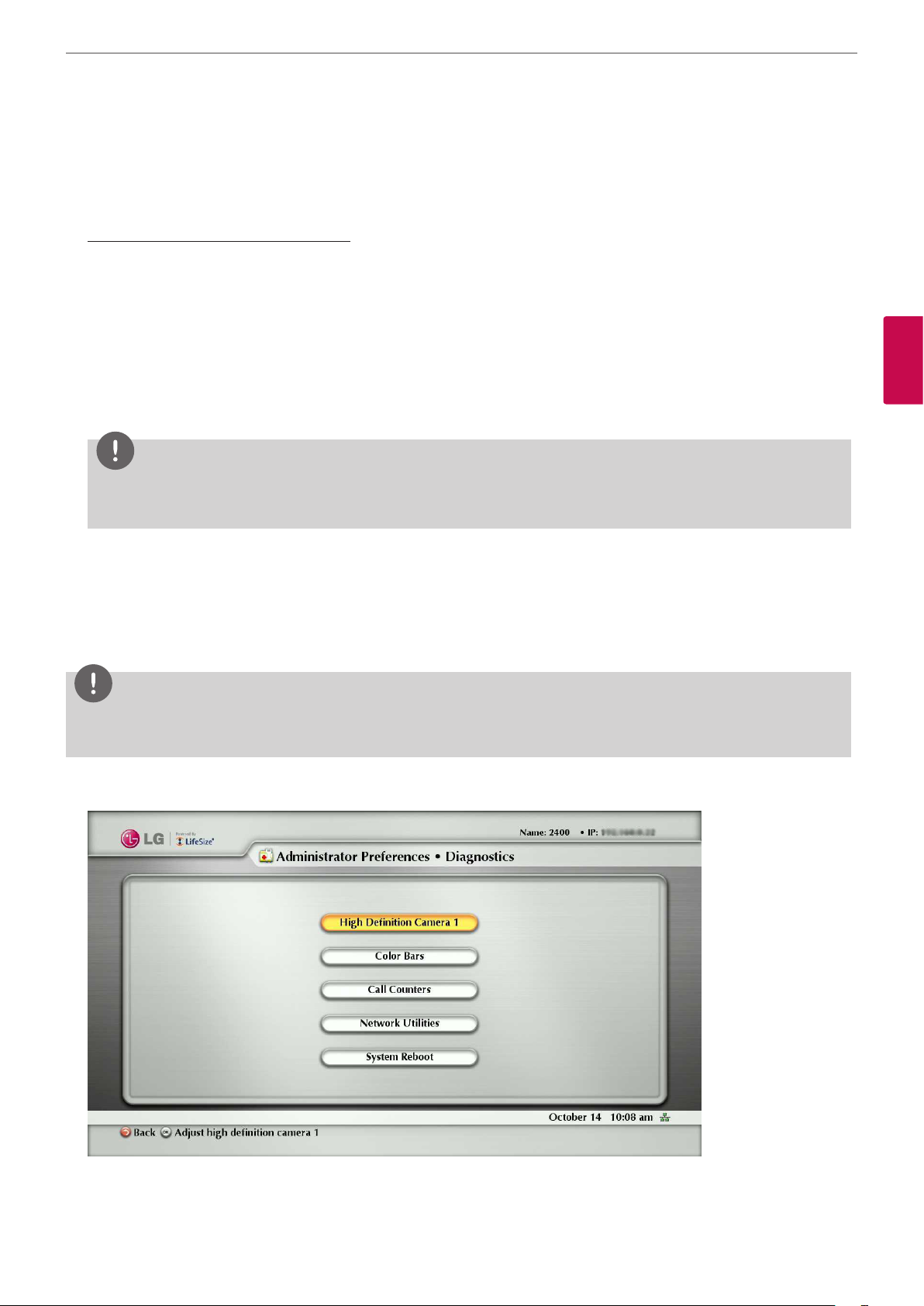
Restoring Default Settings
Administrator preferences contain the conguration of the entire system. You may need to reset the system to its default
state to correct unknown problems you may be experiencing or to return to a known conguration. You can reset the
system from the user interface.
Resetting a System from the User Interface
To reset the system from the user interface, follow these steps:
1. From the System Menu, access Administrator Preferences : System : System Reset.
2. Enter the administrator password.
The system automatically reboots and the administrator password is reset to the default value (1 2 3 4). The user password
also resets to a blank password, enabling users to access User Preferences without a password. The Initial Conguration
screen appears.
You must complete the initial conguration screens to complete the reset.
NOTE
If you reset the system using a remote access method, you must complete the reset from the user interface by navigating
the initial conguration screens and pressing OK on the remote control when prompted to save the conguration.
Installation
49
3
Installation
Using Diagnostics Preferences and Tools
Diagnostic preferences and tools that are available to all users include high-denition camera preferences and a system reboot
option.
Administrators can access these preferences and tools through User Preferences or Administrator Preferences : Diagnostics.
NOTE
In the web administration interface, to view the eect of changes made to camera diagnostic preferences on the Diagnostics :
Cameras page, click Save Changes and then Refresh.
Diagnostic preferences and tools, available only to administrators in Administrator Preferences : Diagnostics, include call
counter statistics, color bar settings, and network utilities.
Page 50

Installation
50
Using Camera Diagnostic Preferences
You can use the camera diagnostic preferences in User Preferences or Administrator Preferences : Diagnostics to adjust
camera brightness and white balance and correct for some types of icker that may appear in the video.
Using Color Bars
You can check the monitor condition using the Administrator Preferences : Diagnostics: Color Bars.
Using Call Counters
You can check how many times you have called and how much time you have called since the last system reboot and reset
using the Administrator Preferences : Diagnostics: Call Counters.
Using Network Utilities
3
Installation
You can troubleshoot network connection issues with your system using the ping and traceroute utilities in Administrator
Preferences : Diagnostics: Network Utilities. The ping command tests responsiveness between two devices. The
traceroute command tests responsiveness and traces the path of a packet from one device to the other.
Rebooting the System
The system reboots when you do any of the following:
• Reboot the system (Administrator Preferences or User Preferences : Diagnostics : System Reboot).
• Reset the system to its default state (Administrator Preferences : System : System Reset).
• Restore a system conguration using System Restore in the web administration interface (Preferences : System : System
Reset : System Restore).
• Enable or disable IPv6 (Administrator Preferences : Network : General)
• Change the VLAN Tag preference (Administrator Preferences : Network : General).
• Change TCP reserved ports (Administrator Preferences : Network : Reserved Ports).
• Change the UDP signaling port, enable or disable TCP or TLS signaling, or change the TCP or TLS signaling ports
(Administrator Preferences : Communications : SIP.)
• Upgrade the system software from the web administration interface (Maintenance : System Upgrade).
All users can reboot the system by accessing User Preferences : Diagnostics : System Reboot from the main screen.
Administrators can also reboot the system by accessing Administrator Preferences : Diagnostics : System Reboot. Select
Yes when prompted to conrm the reboot. To reset the system to its default state, refer to “Restoring Default Settings” on
page 49.
NOTE
Do not unplug the power cord from the system to reboot it.
Page 51
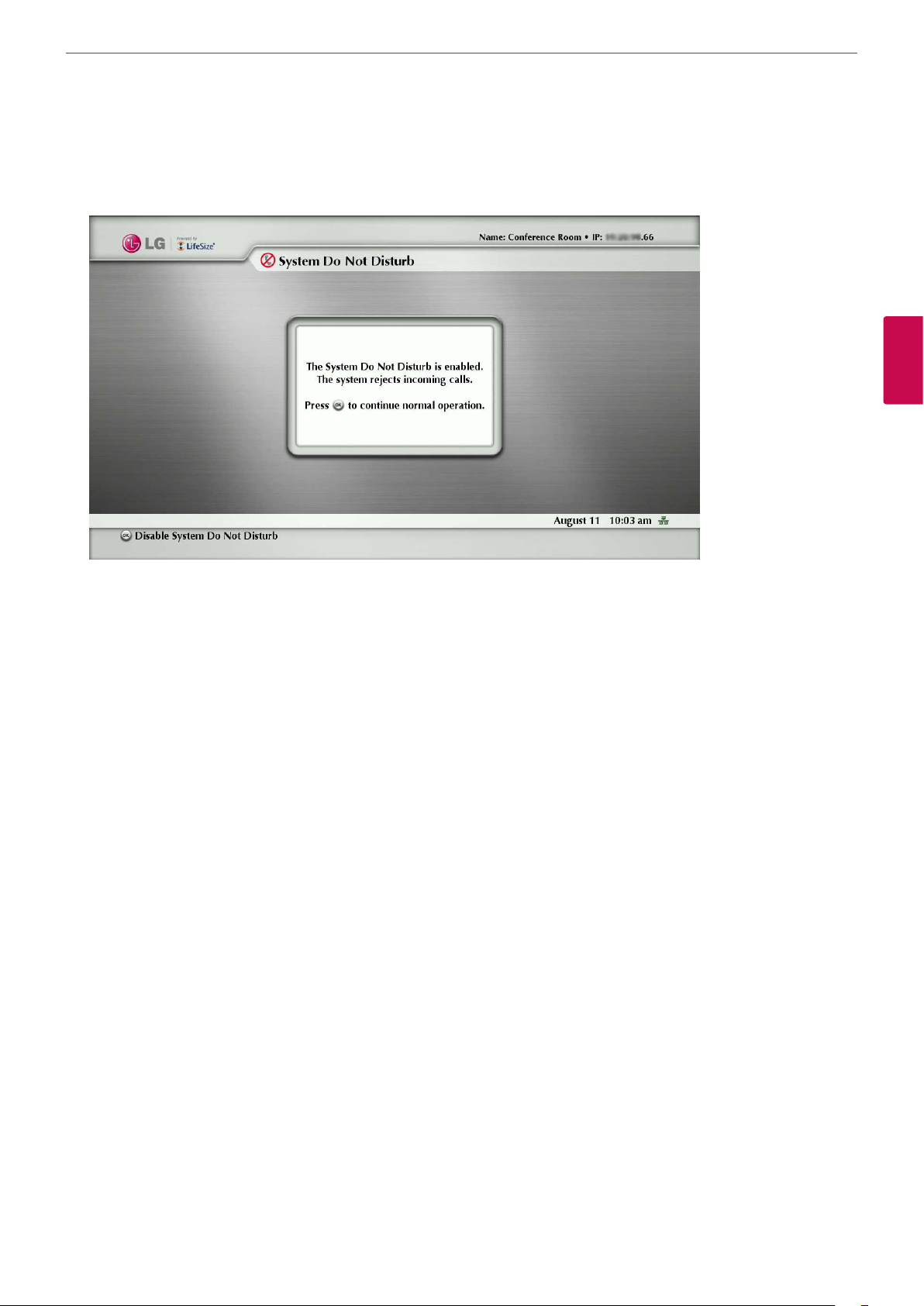
Do Not Disturb
Activate the system Do Not Disturb feature. For more information, refer to “Answering or Rejecting a Call” on page 58.
Installation
51
3
Installation
Page 52

Installation
52
Exclusive Web Administration Features
You can perform the same administrative conguration from the web administration interface that is available from the user
interface. The web administration interface contains the following additional features not available from the user interface.
Using Advanced Directory Features
Advanced usage of the directory is available only from the web administration interface. On the Directory tab, the List All button
retrieves the current directory data. You can import and export entries to and from the local directory using the Import and
Export buttons; you can export entries from the corporate directory. Clear All deletes all entries in the local directory. Search
enables you to locate a specic entry in the directory.
When importing and exporting directory entries from the web administration interface, use a text editor that supports UTF-
3
8 encoding to view or edit the data. Double-byte characters are not supported in directory entries imported using the web
Installation
administration interface.
Saving and Restoring a System Configuration
You can save and restore a system conguration only from the web administration interface.
NOTE
System restore is not supported with the FireFox browser or other browsers based on Mozilla code.
The System Save feature creates a text le that contains command line interface commands to restore a saved conguration. The
saved conguration includes all the preferences that can be set through the command line interface, except the command line
interface password and the password for the default SNMP user. You can edit the le manually to customize the conguration.
The System Restore feature restores a system conguration using the saved conguration le. For more information about
editing commands in the conguration le and saving and restoring a system conguration using the command line interface,
refer to LifeSize Passport Automation Command Line Interface.
NOTE
Conguration preferences and options vary across the system software releases. Restoring a system conguration using a
le saved from a dierent model or software release may produce unexpected results. LG recommends that you restore a
conguration that was saved from the same system or the same system model and software release.
To save a system conguration from the web administration interface, follow these steps:
1. In the web administration interface, navigate to Preferences : System : System Reset. If you wish to save system
passwords in the le, select Save passwords. Passwords saved with this option are not encrypted.
2. Click System Save.
3. In the Download le dialog box, click Yes.
4. When prompted, choose a location in which to save the conguration le and then click Save.
To restore the system conguration from the web administration interface, follow these steps:
1. Ensure that a saved conguration le exists before performing a restore.
2. If you chose not to save passwords when you saved the conguration le, passwords appear in the le as tokens
surrounded by ### characters and FIX: precedes the command in the conguration le, for example:
FIX: set admin password ###Password###
If you wish to replace these tokens with passwords before using the le to restore a system, delete FIX: and replace
###token### with the password. If you do not edit these lines, error 09 (invalid command) appears in the command
output when you restore the system; the FIX: lines are ignored; and values previously set for the passwords remain
unchanged.
Page 53

Installation
3. Close all calls connected to the system. If calls are connected when you perform a restore, a dialog appears prompting
you to continue or cancel the restore. If you continue, the system restore process terminates the calls.
4. In the web administration interface, navigate to Preferences : System : System Reset.
5. Click System Restore.
6. If an error dialog appears, examine the errors. You may wish to copy and paste the errors into a text editing program for
analysis and troubleshooting. Errors due to the presence of FIX: lines identify commands with token passwords that were
not manually edited. Other errors may indicate a problem with restoring a specied preference or restoring the entire
conguration. For a description of the error codes that can appear, see “Standard Return Codes” in the LifeSize Passport
Automation Command Line Interface manual.
7. Click Continue. The system reboots and a dialog appears indicating that the restore was successful.
53
Copying Screen Text to the Clipboard
The web administration interface supports copying data from most screens to the operating system clipboard. This feature
facilitates troubleshooting by enabling you to paste conguration information into an email or text editing application. If a
screen supports this feature, a Copy button appears in the lower right corner of the screen. Click the Copy button to copy the
data on the screen to the clipboard.
Downloading Call History
You can download call history as a comma separated value le (.csv le extension) from the Diagnostics page in the web
administration interface. Click Call History and then click Download Call History. When prompted, choose a location to save the
le. The call history le contains the same output that is produced when you execute the following command in the command
line interface:
status call history -f -?
Downloading call history from the web administration interface retrieves a maximum of 26 records. You can retrieve up to
1 000 records using the command line interface. Restoring a system to default settings, or executing the set system clean -C
command from the command line interface, deletes call history from the system. For more information, refer to LifeSize Passport
Automation Command Line Interface manual.
Upgrading System Software
3
Installation
You can upgrade your system software and manually install a license key only from the web administration interface. For more
information, refer to “Upgrading your System Software” on page 54.
Page 54

Installation
54
Managing Calls from the Web Administration Interface
You can place calls from the Directory tab by selecting an entry and clicking Dial. Dialing an entry from the directory invokes
the Call Manager. The Call Manager tab includes all call management features that are available to users. When you move the
pointer over an interface element, a tool tip appears to assist you with identifying the call management feature associated with
that element. Data that appears in the Call Manager refreshes every ve seconds.
Upgrading your System Software
To upgrade the software for your system, follow these steps:
3
1. Access www.lifesize.com/support.
Installation
2. Click the Download Software button.
3. Enter your serial number (located on the back of your system and on the System Information page).
4. Click the link for the software version you wish to download.
5. Download it to a local directory on your system.
6. Access the web administration interface for your system. Refer to “Administration from a Web Browser” on page 28.
7. Click the Maintenance tab.
8. Click System Upgrade.
9. If your upgrade requires you to reset the system to the original default settings, select the Reset to Default State check box.
10. Browse for the upgrade le you downloaded in step 5.
11. Click Upgrade.
NOTE
If calls are connected to the system, a dialog appears prompting you to continue or cancel the upgrade. Click Yes, to
continue with the upgrade and disconnect the active calls. The upgrade may take several minutes; do not disrupt the
upgrade process. During an upgrade, a status screen appears in the display connected to the system. Users cannot cancel
the screen, and the system rejects incoming calls.
12. A system upgrade status message appears when the upgrade is complete. Close the status window and close the
administrator conguration window.
13. Your system is ready to use. If you selected the Reset to Default State check box in step 9, you must rst recongure your
system.
Troubleshooting Upgrade Failures
If attempts to upgrade software for your system fail, follow these steps:
1. Ensure you have a valid upgrade image.
2. Reboot the system.
3. Attempt the upgrade again.
4. If a second attempt fails, note the error code returned.
5. If problems persist, please contact the authorized service center or where you purchased.
Page 55

Upgrade Error Codes
Following are the error codes you may receive when an upgrade fails.
Code Problem Description
1 Internal error The system is missing critical les.
Installation
55
2
Switch to upgrade
failed
3 Write failed
4 Read failed
5
6
7
Upgrade script
failed
Unable to run
upgrade script
Unable to mount
upgrade partition
The command to set the active partition failed.
A write failure occurred during copying of the image to the upgrade partition. This
typically occurs when using an upgrade image for another LifeSize product.
Reading incoming data failed during the uploading of the image. This typically occurs if
the connection is broken during the upload.
After the image has been successfully uploaded the system runs an upgrade script for
nal processing. This error indicates a failure in that script. This typically occurs when
using an upgrade image for another product.
The system was unable to run the upgrade script. This typically occurs when using an
upgrade image for another product.
After the image has been copied to the system, the system failed to mount the image.
This typically occurs if the upgrade image is corrupt or when using an upgrade image
for another product.
8 No permission The system failed to read the upgrade partition.
9 Corrupt image
The upgrade image is corrupt and unusable. This typically occurs due to a bad image or
errors during upload to the device.
3
Installation
10 Bad argument
11 Invalid signature
12 Decrypt failed
13 Developer system
An invalid argument was submitted to the upgrade process. This typically occurs when
using an upgrade image for another product.
The encryption signature is invalid. This typically occurs if the image is corrupt or
compromised.
The system was unable to decrypt the upgrade image. This typically occurs if the image
is corrupt or compromised.
The system is congured for development and can only be upgraded by a LG
representative.
14 Upgrade in progress An upgrade is already in progress. The system only supports one upgrade at a time.
15
Upgrade license
expired
A current license key for upgrading the system software does not exist on the device.
Contact your authorized partner to renew your maintenance agreement.
Page 56

Operation
56
4
Operation
Near End Video Quality
Before you place a call, examine the near end video image of the camera. If the image ickers, colors appear unbalanced, or the
image appears too dark, you may need to adjust the room lighting or camera brightness and whitebalance.
Placing a Call
4
Operation
You can place a video or voice call with your VCS system in the following ways:
• Select a stored number from the REDIAL list on the main screen or from the directory.
• Manually dial a number using the Video Call or Voice Call buttons on the main screen.
You can place a call with the IP addresses. This enables systems inside a corporate network without access to a gateway to call
other systems in the network using system IP addresses.
NOTE
When microphone howling occurs during the Video or Voice call, the microphone will be shut o automatically and the icon
for announcing that the microphone is shut o will appear on the lower right-hand corner of the screen automatically.
Placing a Call from the REDIAL List
The REDIAL list on the main screen stores up to 15 recently dialed numbers. A scroll bar appears when more than ve entries are
available for selection. The oldest entry in the list is automatically removed when the system receives a call after the maximum
number of entries has been reached.
The last call placed always appears at the top of the list. The entry includes the name of the system called and an icon that
indicates whether the call was a voice or video call. The entry’s number (and bandwidth if the entry is a video call)
appears below the list when the entry is selected. If the system receives a call, but does not answer it, the call appears in the
REDIAL list as a missed call. The symbol appears next to the name in the entry. Select the entry to display the date and time
of the missed call below the REDIAL list.
To place a call from the REDIAL list, use the arrow keys on the remote control to select an entry and press OK.
To change the bandwidth for a video call on the REDIAL list before placing the call, select Video Call on the main screen, press
OK twice, and use the right arrow key to select the desired bandwidth from the list.
Page 57
Operation
NOTE
• Selecting Auto from the Video Call selection before placing a call does not change the bandwidth selection for an entry
on the REDIAL list that does not have Auto as its last called bandwidth.
• You can adjust the maximum number of entries that appear in the REDIAL list by adjusting the [Maximum Redial
Entries] preference in the User Preferences : Calls menu.
• The [None] option for the [Maximum Redial Entries] preference removes existing entries from the REDIAL list and
prevents new entries from appearing on the list.
• You can also add entries from the REDIAL list to the local directory and manually remove entries or lock them to prevent
them from being automatically removed when the maximum number of entries is reached. For more information, refer
to “Managing the REDIAL List” on page 63.
Placing a Call from the Directory
The directory stores a list of names and numbers from which you can place calls. The directory includes three subdirectories: the
local, corporate and meetings directories. The corporate directory is read only and managed by your administrator.
Entries in the local directory are stored on the system and can be modied.
57
4
Operation
To place a call from the directory, follow these steps:
1. From the main screen, press the button on the remote control to access the directory.
2. Use the arrow keys to select the Local, Corporate or Meetings directory and press OK.
3. Use the arrow keys on the remote control to select the entry that you wish to dial.
You can browse the directory using either the alphabetical or hierarchical method. When you use the alphabetical method,
the entries appear in alphabetical order and you can select an alphabet group in the Browse column to quickly navigate to
an entry. Hierarchies are predened organizational units similar to folders or directories on a computer system. You can place
an entry into a hierarchy when you create the entry or at any time by editing the Hierarchy eld when editing the entry. For
more information about creating hierarchies, refer to “Managing the Directory” on page 64. Using the hierarchical method,
you can select a hierarchy in the Browse column to locate an entry. To move down one level in Browse, press OK. To move up
one level, press the button. You can also use the and keys on the remote control to move up or down a page of
entries when an entry is selected.
4. Press OK on the remote control to place the call.
NOTE
• If your site uses LDAP (Lightweight Directory Access Protocol) to authenticate users, you can import users from the
LDAP server to corporate directories.
• If an entry in the local or corporate directory has more than one number, the
column. Press OK and select the number you wish to call. Press OK to place the call.
symbol appears in the NUMBERS
• You can also add, remove or edit entries in the directory. For more information, refer to “Managing the Directory” on
page 64.
Manually Dialing a Number from the Main Screen
Use the Video Call and Voice Call selections on the main screen to dial a video or voice number manually using the remote
control.
Manually Dialing a Video Number
To dial a video number manually from the main screen, follow these steps:
1. Use the arrow keys on the remote control to select Video Call and press OK.
Page 58

58
Operation
2. Enter the number you wish to call. The last manually entered number appears by default. To edit the number, use the
following keys:
• The button behaves as the backspace.
• The button displays the keyboard from which you can enter alphanumeric characters. Use the arrow keys to
navigate to the character you wish to enter and press OK.
• The button changes the text entry method (indicated at the bottom of the screen).
NOTE
The 0x1a option enables you to enter an IPv6 address when your system is connected to an IPv6 network. If IPv6
addressing is enabled on your system, the IPv6 address of the system appears on the System Information page in
the System Menu. If you enter an IPv6 address, the system you are calling must support IPv6 addressing for the call
to connect.
• Press OK to exit the eld.
4
Operation
3. Navigate to the list that appears next to the entry box for numbers and choose a value for the maximum bandwidth for
the call. Press OK to access the list, use the arrow keys to select a value, and press OK again to save your selection. (The
selected bandwidth value can aect the quality of the call. Select the proper bandwidth for the network environment of
the far end system. The default value is Auto.).
4. Press the call button to dial the number.
Manually Dialing a Voice Number
To dial a voice number manually from the main screen, follow these steps:
1. Use the arrow keys on the remote control to select Voice Call and press OK.
2. Enter the number you wish to call. The last manually entered number appears in this eld by default. To edit the number, use
the following keys:
• The button changes the text entry method (indicated at the bottom of the screen).
• The button behaves as the backspace.
• The button displays the keyboard from which you can enter alphanumeric characters. Use the arrow keys to
navigate to the character you wish to enter and press OK.
3. Press the call or OK button to place the call.
Answering or Rejecting a Call
You can congure your system to automatically answer incoming calls by setting preferences in User Preferences : Calls menu
as follows:
• Auto Answer: If it is set to Enabled, the system automatically answers the rst incoming call. If set to Disabled (the default),
you must manually answer incoming calls.
If your system is congured for answering calls manually, choose one of the following options when an incoming call arrives:
- Select Answer and press OK to accept the call.
- Select Ignore and press OK to reject the call.
• Auto Answer Mute: If it is set to Enabled (the default), and the Auto Answer preference is set to Enabled, the system is muted
when a call connects.
Page 59

Operation
Using System Do Not Disturb
You can enable the system Do Not Disturb feature to show only the background image of the main screen with the status and
navigation bars and a system Do Not Disturb message. When the system Do Not Disturb feature is enabled, the system responds
only to the volume control buttons and the OK button on the remote control. Callers hear a busy signal and missed calls appear
in the REDIAL list. Consider using this feature, for example, if you are using the meeting room for a purpose other than a video
conference and do not wish to be disturbed by incoming calls.
To enable this feature, follow these steps:
1. From the main screen, access the system menu by pressing the button on the remote control.
2. Use the down arrow key to select Do Not Disturb.
3. Press OK. A dialog box appears indicating that the system Do Not Disturb feature is enabled.
NOTE
If you want to return to the normal system operation, press the OK button.
59
4
Operation
Managing a Call
During a call, you can view information about the status of the call and the identity of the connected caller. You can also manage
audio output and video images.
Call Status
When you place a call with your system, a Call Status dialog appears. The Call Status dialog shows the IP address that you are
attempting to call and the status of the call (for example, dialing, ringing, connecting, answered, or unavailable).
Caller ID
When your video call is answered, video from the far end appears in your display. In the upper-left corner of the far video image,
the caller ID (IP address) of the far end system appears. One or more of the following icons may appear next to the caller ID to
represent information about the call.
Icon Description Icon Description
Video call. Voice call.
A video call that is encrypted.
A voice call that is encrypted.
NOTE
The icon appears in the Call Status,
Call Manager list, and Call Statistics list.
Microphones are muted on the far end
system.
NOTE
The icon appears in the Call Status, Call
Manager list, and Call Statistics list.
Page 60

Operation
60
Hiding or Showing User Interface Elements
By default, the system information, status bar and navigation bar fade from the screen after a call has been connected for
10 seconds. This interval resets after any interaction with the system. You can adjust the duration of the fade out interval by
adjusting the Fade Out Timeout preference in User Preferences : Appearance menu. To hide or show these user interface
elements at any time during a call, press the button.
NOTE
The user interface does not hide if the system is overheating. System overheating icons appear in the status bar.
Managing Audio
You can identify the video caller who is speaking in the call, adjust the volume of the audio, and mute the active microphone.
Identifying the Dominant Speaker
4
Operation
When a video participant in a call is speaking, the dominant speaker icon appears in the display in the video image from
that participant.
Adjusting Volume
To adjust the volume in a call, use the button on the remote control. You can also adjust the active microphone volume,
or the treble and bass levels for audio out by adjusting preferences in [User Preferences > Audio] menu.
Muting the Active Microphone
Pressing the mute button on the remote control mutes the active microphone. When the near side active microphone
is muted in a call, the symbol appears.
Managing PIP
Your display shows the far-end and near-end video conferencing sites in addition to the menus and video images from
connected video sources.
Picture-In-Picture (PIP) is a smaller window placed in one of the corners of the call screen. This second image is placed on top
of the main image and always displays the primary (near) input by default. You can change the default setting so that PIP never
appears or always appears by adjusting the User Preferences : Appearance : Picture in Picture preference.
Managing Video Layout
During a call, video from the connected caller appears in your display. You can change the screen layout of near and far end
video that appear in the monitor.
To change the screen layout, press the button.
Page 61

No
Presentation
Far End Video
Near End Video
Near End Video
Screen Layout
Operation
61
During a
Presentation
Far End Presentation
Near End Video
Far End Video
Near End Video
Far End Video Near End Video
Far End Video Near End Video
Near End Video
4
Operation
Far End Presentation
Far End Presentation Near End Video
Far End Video
Far End Video
Near End Video
Page 62

Operation
62
Viewing Call Statistics
To view statistical information about a call, follow these steps:
1. During a call, press the button.
2. Audio and video statistics for the current call appear on the screen.
Two columns of statistics, Receive and Transmit appear. The total bandwidth used for audio and video appear alongside each
column heading. Each column has a video and audio block.
• Video statistics include the following:
- resolution shows the resolution, in pixels, of the video image transmitted or received.
- codec shows the video codec used to compress and decompress the video.
- bandwidth shows the amount of video data transferred per second in kilobits.
- frame rate shows the video frame rate in frames per second.
• Audio statistics include the following:
- codec shows the audio codec used to compress and decompress the audio.
4
Operation
- bandwidth shows the amount of audio data transferred per second in kilobits.
- packet rate shows the amount of audio data packets transferred or received per second in kilobytes.
• Both the Audio and Video block include the following:
- jitter shows the variation, in milliseconds, in the time between packets arriving, caused by network congestion, timing
drift or route changes.
- packet loss shows the number of packets of data that fail to reach their destination. Packet loss can be caused by a
number of factors, including signal degradation over the network medium, oversaturated network links, corrupted
packets rejected in-transit, faulty networking hardware, maligned system drivers or network applications, or normal
routing routines.
- cumulative shows the up to date count of packets lost in the call.
- percentage shows packet loss as a percentage of the total packets sent.
• The following additional information appears below the Audio statistics block:
- the call duration
- the make and model of the far end video communication device and the software version it is using
- the call protocol (H.323 or SIP, for example)
3. To hide the statistics, press the button again. Statistics automatically refresh every 5 seconds and hide after 5 minutes.
Ending a Call
You can end a call using any of the following options:
• hang up button on the remote control
• Call Manager dialog
• REDIAL list
Ending a Call from the Call Manager
To hang up a call from the Call Manager dialog, follow these steps:
1. From any call screen, press OK.
The Call Manager dialog appears.
2. To hang up a call, press OK again to end the call.
Page 63

Operation
Ending a Call from the REDIAL List
To hang up a call from the REDIAL list, follow these steps:
1. Press the button to return to the main screen.
2. On the REDIAL list, an orange LED indicator appears to the left of the voice or video number currently in the call. Use the
arrow keys to select the entry.
3. Press OK.
Managing the REDIAL List
Locking and Unlocking Entries in the REDIAL List
You can lock and unlock entries in the REDIAL list. Locking an entry prevents it from being removed after the maximum number
of entries in the list has been reached. The lock symbol appears next to the name in the entry when the entry is selected.
63
NOTE
Locking an entry does not prevent it from being removed from the list manually.
To lock or unlock an entry in the REDIAL list, follow these steps:
1. Using the arrow keys on the remote control, select the entry you wish to lock or unlock.
2. Press the button.
3. Select Lock (or Unlock if the entry is locked) from the menu, and press OK.
Removing an Entry from the REDIAL List
To remove an entry from the REDIAL list, follow steps below:
1. Using the arrow keys on the remote control, select the entry you wish to remove.
2. Press the button.
3. Select Remove from the menu, and press OK.
Adding a REDIAL List Entry to the Directory
You can add an entry from the REDIAL list to the local directory.
4
Operation
NOTE
An administrator can choose to hide the local directory from users, in which case, a user cannot perform this task.
1. Using the arrow keys on the remote control, select the entry you wish to add to the directory.
2. Press the button.
3. Select Save on the menu and press OK.
4. Press OK again to close the conrmation dialog.
Page 64

Operation
64
Managing the Directory
If you have access to the local directory, you can add, remove or edit entries.
Adding an Entry to the Local Directory
You can create up to 1 000 entries in the local directory. To add an entry to the local directory, follow the steps below:
1. Access the directory by pressing the button from the main screen.
2. Using the arrow keys, select the Local directory.
3. Select the Add New Entry button and press OK.
4. Use the arrow keys to select elds in the New Directory Entry screen. Press OK to enter a value in a selected eld. Enter a
system name, video and voice numbers, and IP address or ISDN numbers. If necessary, press the button to change the
method of text entry for text elds, or press to access the keyboard. After entering a value, hide the keyboard (if you
4
Operation
used it to enter the value) and press OK to exit the eld.
5. If a hierarchy has been predened for the local directory, in the Hierarchy eld enter the path to the location in the hierarchy
in which to place the entry. Hierarchies can be dened, for example, by location or department. You must identify the
full path (separated by commas) of a predened hierarchy in which to add an entry prior to completing the new entry
screen. If you leave the Hierarchy eld empty, the new entry is inserted at the top of the hierarchy (if dened) or is grouped
alphabetically.
For example, suppose your administrator dened a hierarchy by location where Home Oce is the top of the hierarchy, and
Sales Oce 1 and Sales Oce 2 are at the next level below the Home Oce. To place an entry in Sales Oce 2, the value for
Hierarchy is Home Oce, Sales Oce 2.
6. When you have completed the elds, select Add Entry and press OK.
Copying an Entry from the Corporate to the Local Directory
You can copy an entry from the corporate directory to the local directory.
1. Access the directory by pressing the button from the main screen.
2. Select the Corporate directory.
3. Select the entry you wish to copy to the local directory.
4. Press the button.
5. Select Copy to local and press OK.
6. Press OK to save the entry.
Removing an Entry from the Local Directory
You can remove an entry from the local directory.
1. Access the directory by pressing the button from the main screen.
2. Select the Local directory.
3. Select the entry you wish to remove.
4. Press the button.
5. Select Remove and press OK.
6. Select Yes and press OK.
Page 65

Operation
Editing an Entry in the Local Directory
You can edit an entry in the local directory.
1. Select the entry you wish to edit.
2. Press the button.
3. Select Edit from the menu, and press OK.
4. Modify values in the Edit Directory Entry dialog.
4-1. Press OK to select a eld you wish to modify. If necessary, press the button to change the method of text entry for
text elds.
4-2. After completing your changes, press OK to exit the eld.
5. Using the arrow keys, select Save Changes and press OK.
Adding an Entry to the Meetings Directory
To add an entry to the meetings directory, follow the steps below:
1. Access the directory by pressing the button from the main screen.
65
4
Operation
2. Using the arrow buttons, select the meetings directory and press OK.
3. Select the [Add New Entry] button and press OK.
4. Select the Meeting Name option and enter the meeting name.
5. Select the Hierarchy option and enter the hierarchy name.
6. Select the directory among the Local, Corporate and Both and press OK.
7. Select the entry you wish to add from the Available Entries list and press OK. You can add only the one entry for the
participants.
8. Select the [Add Meeting] button and press OK.
Page 66

Monitor settings
66
5
Monitor settings
Customizing OSD settings
Navigation button overview
Button OSD Description
• Displays the main menu.
MENU
• Enter the MENU option.
• Move to the previous menu.
• Displays the main menu.
MODE
5
Monitor settings
AUTO
INPUT
EXIT EXIT Exit the OSD setup menu.
• Enter the MODE option.
• Select the sub-menu title.
• Decrease the option value.
• Displays the main menu.
• Set the image adjustment automatically.
• Increase the option value.
• Displays the main menu.
• Change the input source.
• Enter the sub-menu option.
• Select the sub-menu option.
MENU settings
1. Press the MENU button to access the main menu.
2. Press the MENU button again to display the sub-menu.
3. Use the MODE or AUTO button to select the sub-menu title.
4. Press the INPUT button to enter the selected sub-menu.
5. Use the INPUT button to select the options.
6. Use the MODE or AUTO button to set the value.
7. Press the MENU button to return to the previous menu.
8. Press the EXIT button to exit the menu.
Page 67

MENU Supported Input Description
Monitor settings
67
PICTURE BRIGHTNESS HDMI (Digital signal input.)
D-SUB (Analog signal input.)
CONTRAST You can adjust the level of the Contrast. Increases or decreases
SHARPNESS You can adjust the level of the Sharpness..
BLACK LEVEL HDMI (Digital signal input.) Sets black level of the screen to proper level. This function is
COLOR COLOR TEMP HDMI (Digital signal input.)
PRESET Select the screen color.
D-SUB (Analog signal input.)
RED This option is activated when you select the [COLOR TEMP]
GREEN This option is activated when you select the [COLOR TEMP]
You can adjust the level of the Brightness. The lower the level,
the softer the image.
the gradient of the video signal.
available in the HDMI mode only.
• LOW: The reection of the screen gets darker.
• HIGH: The reection of the screen gets brighter.
Select PRESET or USER option to set the value.
• sRGB: Set the screen color to t the sRGB standard color
specication.
• 6500K: Slightly reddish white.
• 7500K/8500K: Set the screen color to default value.
• 9300K: Slightly bluish white.
option to [USER]. Set your own red color levels.
option to [USER]. Set your own green color levels
5
Monitor settings
BLUE This option is activated when you select the [COLOR TEMP]
option to [USER]. Set your own blue color levels.
GAMMA Set your own gamma value. : GAMMA0 / GAMMA1 / GAMMA2
On the monitor, high gamma values display whitish images
and low gamma values display blackish images.
DISPLAY HORIZONTAL D-SUB (Analog signal input.) To move image left and right.
VERTICAL To move image up and down.
CLOCK To minimize any vertical bars or stripes visible on the screen
background.
The horizontal screen size will also change.
PHASE To adjust the focus of the display.
This item allows you to remove any horizontal noise and clear
or sharpen the image of characters.
OVERSCAN HDMI (Digital signal input.) If you set to [ON], the overscan function is activated.
This function is available in the HDMI mode only.
VOLUME - HDMI (Digital signal input.)
D-SUB (Analog signal input.)
Use the MODE or AUTO button to adjust the output volume.
If you press INPUT again, the system volume is muted.
Page 68

Monitor settings
68
OTHERS LANGUAGE HDMI (Digital signal input.)
D-SUB (Analog signal input.)
POWER
INDICATOR
WHITE
HDMI (Digital signal input.)
D-SUB (Analog signal input.)
D-SUB (Analog signal input.) If the output of the video card is dierent to the required
BALANCE
FACTORY
RESET
HDMI (Digital signal input.)
D-SUB (Analog signal input.)
MODE settings
1. Press the MODE button to access the main menu.
5
Monitor settings
To choose the language in which the control names are
displayed.
Use this function to set the power indicator on the front side of
the monitor to ON or OFF.
If you set OFF, it will go o.
If you set ON at any time, the power indicator will automatically
be turned on.
specications, the color level may deteriorate due to video
signal distortion. Using this function, the signal level is adjusted
to t into the standard output level of the video card in order to
provide the optimal image. Activate this function when white
and black colors are present in the screen.
If you press MODE or AUTO button, restore all factory default
settings except “LANGUAGE.”
2. Press MODE button again to display the sub-menu.
3. Use the MODE or AUTO button to select the sub-menu title.
4. Press INPUT button to enter the selected sub-menu.
5. Use the MODE or AUTO button to select or set the options.
6. Press the MENU button to return to the previous menu.
7. Press the EXIT button to exit the menu.
MENU Description
STANDARD Adjusts the image for the normal environment.
Optimizes the video image for a cinematic look to enjoy movies as if you are in a
movie theater.
• ENGINE
f
MOVIE
GAME Optimizes the video image for a fast gaming screen such as on PCs or games.
SPORTS
Optimizes the video image for high and dynamic action by emphasizing primary
colors such as white, grass, or sky blue.
WIDE Switch to full screen mode according to input image signal.
ORIGINAL
RATIO
ORIGINAL
Change the input image signal ratio to original.
This function works only if input resolution is lower than monitor ratio (16:9).
NORMAL The PhotoEect function is disabled.
GAUSSIAN BLUR This menu changes the screen to be more colorful and smoother.
PHOTO EFFECT
SEPIA This menu changes the screen to a Sepia tone (brown color).
MONOCHROME This menu changes the screen to a Gray tone (black-and-white Picture).
Page 69
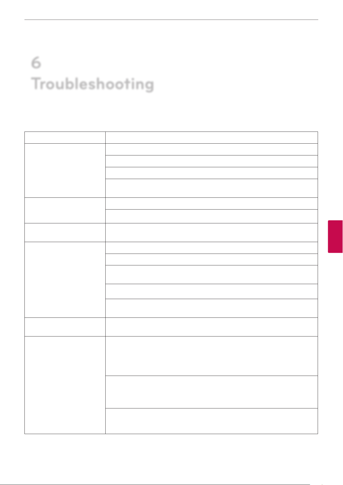
6
Troubleshooting
Check the following guide for the possible cause of a problem before contacting service.
Symptoms Solutions
Troubleshooting
69
The system power does not turn
on.
The system power is turned on
but no video data is displayed
on the monitor.
The subject is not clear enough
to see.
The remote control is not
working.
Check the power cable is connected correctly.
Check the input voltage is correct.
Check the main power switch is turned on.
If the system power does not turn on even if the power cable is connected correctly,
please contact the service center.
Check the input mode of the system. Make sure the mode is set to VCS.
Unplug the power cable and plug in again.
Adjust the camera brightness and white balance in User Preferences : Diagnostics
setting menu.
Check the battery.
Make sure that the battery polarities are connected with (+) and (-) matched correctly.
Check the remote control contains three AAA batteries that are in good working
condition.
Verify whether objects are obstructing the sensor on the front of the camera.
Check that the LED on front of the camera ashes bright blue when you use the remote
control.
6
Troubleshooting
The image is not visible. Verify that the blue LED on the front of the camera is lit, indicating that power is active,
and reboot the system if necessary to verify that the camera turns on.
The sound is not audible If you are unable to hear the ringer when an incoming call arrives, adjust the Ring Tone
Volume preference in User Preferences : Audio. Mued audio reception from the far
side may be caused by highly reverberant rooms. If you are experiencing poor audio
reception, add more sound absorbency to the room and speak in close proximity to the
microphone.
Degradation in audio quality can also be caused by faulty microphones or dust and debris
on the microphones. Do not use any kind of liquid or aerosol cleaner on the camera that
includes microphones. A soft, slightly damp cloth is sucient to clean the top surface of
the units if necessary.
Ensure both ends are not muted. Verify that the audio out cables are properly connected
to the monitor and that any external speaker systems are powered and congured
correctly.
Page 70

Troubleshooting
70
You can not make a call. If a call does not successfully connect, verify that you have dialed a working number and
that the far end destination is powered on and available. Verify that the network is ready
and available. Network status is indicated at all times in the status bar. If the VCS system
is connected to the local network, a green network status icon appears. A yellow or red
network status icon indicates a problem with the network connection.
6
Troubleshooting
The system does not work with
Reboot the system that is not responding to commands from the remote control.
the remote control.
The message “OUT OF RANGE”
appears on the screen.
This message appears when the signal from the PC (video card) is out of horizontal or
vertical frequency range of the display. See the ‘Specications’ section of this manual and
congure your display again.
The message “CHECK SIGNAL
CABLE” appears on the screen.
The message “OSD LOCKED”
appears on the screen
This message appears when the signal cable between your PC and your display is not
connected. Check the signal cable and try again.
You can secure the current control settings, so that they cannot be inadvertently
changed. You can unlock the OSD controls at any time by pushing the MENU button for
several seconds: the message “OSD UNLOCKED” will appear.
Display Position is incorrect. Press the AUTO button to automatically adjust your display image to the ideal setting.
If the results are unsatisfactory, adjust the image position using the H position and V
position icons in the on-screen display.
On the screen background,
vertical bars or stripes are visible.
Press the AUTO button to automatically adjust your display image to the ideal setting. If
the results are unsatisfactory, decrease the vertical bars or stripes using the CLOCK icon in
the on-screen display.
Any horizontal noise appearing
in any image or characters are
not clearly portrayed.
Do you see an “Unrecognized
Press the AUTO button to automatically adjust your display image to the ideal setting.
If the results are unsatisfactory, decrease the horizontal bars using the PHASE icon in the
on-screen display.
Make sure you check if the video card supports Plug&Play function.
monitor, Plug&Play (VESA DDC)
monitor found” message?
Page 71

7
Appendix
Specifications
ITEM Specication
Viewable image size 60.96 cm Full HD
Brightness, Typical
Contrast Ratio, Typical 1000:1
300 cd/m
2
Appendix
71
Monitor
Video
DFC 5M:1
Response Time, Typical 5 ms
Display frequency range 1 920 x 1 080 @ 60 Hz
Display color 16.7M
Digital Controls with 15 Languages OSD
DDC2B Yes
EDID VESA Standard, Version 1.3
Communication H.323, SIP
Signal Input 15 pin D-Sub Connector
Video Input
Video standard
HDMI Connector
Input Form RGB Analog (0.7 Vp-p/75 Ω), Digital
H.261, H.263, H.263+, H.263++, MPEG4, H.264AVC
H.239 (receive) compliant
Maximum resolutions widescreen 16:9 aspect ratio
All resolutions progressive scanning
All resolutions at 30 frames per second
7
Appendix
Resolution
192 Kbps (432 x 240 pixels) Widescreen FCIF
384 Kbps (720 x 400 pixels) Cable TV
512 Kbps (800 x 448 pixels) DVD resolution
768 Kbps (1 024 x 576 pixels) 2xDVD Resolution
1.1 Mbps or higher (1 280 x 720 pixels) High Denition
resolution
Page 72

72
Appendix
Wide-angle lens with 70 degree eld of view
6 mm, 1.3 Mega pixels HD Color xed camera
Camera
1 280 x720p @ 25 to 30 fps Resolution
Built-in high sensitivity Microphone
G.711, G.722, G.722.1C, G723.1, G.728, G.729, G729a,
MPEG-4 -AAC-LC
High Denition audio
Built-in ringer
Audio standard
Echo cancellation for echo-free calls
Automatic noise reduction ( Noise suppression) /
Comfort Noise Fill
Automatic gain control
7
Appendix
Feature
Other Supported Standards
User Interface
H.221, H.224, H.225, H.231, H.241, H.242, H.245, H.281,
BONDING (ISO13871) via LifeSize Networker, RFC 3261,
RFC 3264, RFC 2190, RFC 3407, RFC 2833
Context sensitive user interface
Graphical user interface call manager
Multiple languages supported
Do Not Disturb mode
Auto Call Establishment
Call Scheduling
Diagnostic logging
Web Interface
Directory Service (H.350)
System Log Reporting
Data sharing
Software Upgrade via internet
Network
Far-End Camera Control (H.224/H.281)
IPv4 & IPv6
AES (FIPS197, H.234/H.235)
NAT / Firewall Client (H.460.17/18/19)
IP Precedence for QoS
DiServ (Diereniated Service)for QoS
RSVP (Resource Reservation Protocol)for QoS
Adaptive Motion Control ( AMC )for QoS
Page 73

Up to 500 local directory entries
Save, Lock, Remove Redial List features
Appendix
73
Environmental Data
Directory & Address Book
Missed call notication
Auto-Discovery directory lookup (patent pending)
LDAP support / H.350 compliant
SNMP
System Management
Backup and Restore capability
Admin and User level password
SNMP security alerts
Ability to disable HTTP, SSH and Telnet services
Security
H.235 (AES) encryption support including strict
compliance
TLS/SRTP support
IEEE 802.1x support
Power AC Voltage 100-240 V, 50/60 Hz, 63 W (1.5 A)
Operating temperature
0 ˚C (32 F) to 40 ˚C (104 F)
Operating Humidity 15 % to 85 %, non-condensing
Storage temperature -20 ˚C (-4 F) to 60 ˚C (140 F)
Dimensions
Storage humidity 10 % to 90 %, non-condensing
Height 499 mm
Weight 8.1 kg
Regulatory Certications
Interface
Width 600 mm
Depth 131 mm
FCC , cUL, CE/CB, C-tick, TUV-bauart, CCC, JQA, VCCI,
KC, KCC
2 x RJ-45 (Network LAN, PC In )
1x HDMI In
1x D-Sub In
1x Mic in
1x Headphone out
7
Appendix
Page 74

Appendix
74
WARRANTY CARD
END USER Name Product
Address of END USER Model
Telephone Dealer Name
Fax Dealer Address
Serial No
Email Address Dealer Telephone
Date of Purchase(yyyy-mm--dd) Dealer Fax
Invoice No. Dealer E-Mail
7
Appendix
1. The warranty card should be completed in full and returned to the dealer within 10 days of purchase. Failure to do so will
make the warranty void.
2. The END USER must ll out the completed warranty card, together with the original invoice to the ocial dealer from which
the END USER purchased the product within the warranty period.
3. Warranty service provided is subject to the terms and conditions described on the relevant side.
Terms and Conditions
1) This Warranty applies for the following from the date of purchase only. The right to request sight of the original proof of
purchase is reserved.
a. 12 months for Hardware
b. 3 months for Software
2) It is the user’s responsibility to ensure that the product is used in accordance with the Manufacturer’s guidelines detailed
in the Instruction Manual supplied with your Video Conference Monitor. Failure to do so may invalidate your Warranty.
3) All warranties will be immediately invalidated if unauthorized repairs or modications are made to the monitor or in any
case of accident, misuse, damage caused by improper installation and altered serial numbers. Pollution of the monitor
with smoke, food, liquid or similar will be deemed as misuse.
4) When this product is sold through LG Electronics’ resale or distribution partners, LG Electronics reserves the right to
collect, repair and return any monitor which has cabinet delement, including security marking. LG Electronics may also
collect units for repair where no suitable replacement is available.
Page 75

Appendix
5) When this product is sold through LifeSize’s resale or distribution partners, LifeSize reserves the right to collect repair and
return any monitor which has cabinet delement, including security marking. LifeSize may also collect units for repair
where no suitable replacement is available.
6) The END USER will be liable for all costs associated with “Invalid Warranty Claims”.
7) Liability is limited to the cost of repair and/or replacement of the unit under warranty.
8) This warranty does not aect the purchaser’s statutory rights.
9) Warranty covers only those defects which arise as a result of normal use of the product, and the warranty for the product
is deemed void if ;
a) The content of the warranty card has been changed, unless certied by an authorized dealer.
b) The serial number has been altered or removed.
c) The product has been damaged through misuse, negligence, fault of voltage supply, improper testing, incorrect
operation or natural disaster.
d) The product has been subject to unauthorized alternating, modication or maintenance by a person other than
authorized by LG Electronics or LifeSize or an Authorized Dealer.
e) The product is not installed in accordance with the instructions furnished by the manufacturer.
75
f ) The END USER fails to provide a warranty card or invoice.
g) The warranty period is over the due term
10) This warranty does not cover the damage done to other equipment used in conjunction with this unit.
11) All defective peripheral devices should be returned together with the whole unit.
12) LG Electronics(or LifeSize) reserves the right to substitute functionally equivalent new or serviceable used parts,LG
Electronics(or LifeSize)’s responsibility is limited to repair, using any parts which may be selected by LG Electronics or
LifeSize or an authorized dealer. Unless otherwise stated herein, the cost of labor is not covered by the warranty.
13) The warranty is valid within the country where the authorized dealer distributes the product.
14) This warranty card will not be re-issued.
15) END USER information provided herewith may be used by LG Electronics(or LifeSize) for the purpose of provision of
product repair related services and for conducting END USER satisfaction surveys, as deemed necessary by LG Electronics
(or LifeSize)
16) Under no circumstances shall LG Electronics (or LifeSize) be liable for any consequential damage caused by the use of a
defective product.
7
Appendix
Page 76

 Loading...