

LG AVNQ36GM1A0 INSTALLATION MANUAL

P/NO : MFL68065208
INSTALLATION MANUAL
AIR
CONDITIONER
www.lg.com
Please read this installation manual completely before installing the product.
Installation work must be performed in accordance with the
national wiring standards by authorized personnel only.
Please retain this installation manual for future reference
after reading it thoroughly.
Single ceiling suspended air conditioner
ENGLISH
ESPAÑOL
PORTUGUÊS

2
TIPS FOR SAVING ENERGY
ENGLISH
• Do not cool excessively indoors. This may be harmful for your health and may consume more
electricity.
• Block sunlight with blinds or curtains while you are operating the air conditioner.
• Keep doors or windows closed tightly while you are operating the air conditioner.
• Adjust the direction of the air flow vertically or horizontally to circulate indoor air.
• Speed up the fan to cool or warm indoor air quickly, in a short period of time.
• Open windows regularly for ventilation as the indoor air quality may deteriorate if the air conditioner is used for many hours.
• Clean the air filter once every 2 weeks. Dust and impurities collected in the air filter may block the
air flow or weaken the cooling / dehumidifying functions.
For your records
Staple your receipt to this page in case you need it to prove the date of purchase or for warranty purposes. Write the model number and the serial number here:
Model number :
Serial number :
You can find them on a label on the side of each unit.
Dealer’s name :
Date of purchase :
Here are some tips that will help you minimize the power consumption when you use the air conditioner. You can use your air conditioner more efficiently by referring to the instructions below:
TIPS FOR SAVING ENERGY

IMPORTANT SAFETY INSTRUCTIONS
3
ENGLISH
IMPORTANT SAFETY INSTRUCTIONS
READ ALL INSTRUCTIONS BEFORE USING THE APPLIANCE.
Always comply with the following precautions to avoid dangerous situations and ensure peak
performance of your product
WARNING
It can result in serious injury or death when the directions are ignored
CAUTION
It can result in minor injury or product damage when the directions are ignored
WARNING
• Installation or repairs made by unqualified persons can result in hazards to you and others.
• The information contained in the manual is intended for use by a qualified service technician
familiar with safety procedures and equipped with the proper tools and test instruments.
• Failure to carefully read and follow all instructions in this manual can result in equipment malfunction, property damage, personal injury and/or death.
Installation
• Don’t use a power cord, a plug or a loose socket which is damaged.
- Otherwise, it may cause a fire or electrical shock.
• For electrical work, contact the dealer, seller, a qualified electrician, or an Authorized Service
Center.
- Do not disassemble or repair the product. There is risk of fire or electric shock.
• Always ground the product.
- There is risk of fire or electric shock.
• Install the panel and the cover of control box securely.
- There is risk of fire or electric shock.
• Always install a dedicated circuit and breaker.
- Improper wiring or installation may cause fire or electric shock.
• Use the correctly rated breaker or fuse.
- There is risk of fire or electric shock.
• Do not modify or extend the power cable.
- There is risk of fire or electric shock.
• Do not let the air conditioner run for a long time when the humidity is very high and a door or
a window is left open.
- Moisture may condense and wet or damage furniture.
• Be cautious when unpacking and installing the product.
- Sharp edges could cause injury. Be especially careful of the case edges and the fins on the
condenser and evaporator.
• For installation, always contact the dealer or an Authorized Service Center.
- There is risk of fire, electric shock, explosion, or injury.
!
!
!
4
IMPORTANT SAFETY INSTRUCTIONS
ENGLISH
• Do not install the product on a defective installation stand.
- It may cause injury, accident, or damage to the product.
• Be sure the installation area does not deteriorate with age.
- If the base collapses, the air conditioner could fall with it, causing property damage, product
failure, and personal injury.
• Do not turn on the breaker or power under condition that front panel, cabinet, top cover, control box cover are removed or opened.
- Otherwise, it may cause fire, electric shock, explosion or death.
Operation
• Do not store or use flammable gas or combustibles near the product.
- There is risk of fire or failure of product.
CAUTION
Installation
• Always check for gas (refrigerant) leakage after installation or repair of product.
- Low refrigerant levels may cause failure of product.
• Install the drain hose to ensure that water is drained away properly.
- A bad connection may cause water leakage.
• Keep level even when installing the product.
- To avoid vibration or water leakage.
• Do not install the product where the noise or hot air from the outdoor unit could damage the neigh-
borhoods.
- It may cause a problem for your neighbors.
• Use two or more people to lift and transport the product.
- Avoid personal injury.
• Do not install the product where it will be exposed to sea wind (salt spray) directly.
- It may cause corrosion on the product. Corrosion, particularly on the condenser and evaporator
fins, could cause product malfunction or inefficient operation
!
Batteries :
Do not burn, do not try to open it, do not dispose in ordinary trash. Preserve
environment and your health.
After use, batteries must be delivered to the merchant or service authorized
network (Conama number 401 dated 11/2008).

TABLE OF CONTENTS
5
ENGLISH
2 TIPS FOR SAVING ENER-
GY
3 IMPORTANT SAFETY
INSTRUCTIONS
6 INSTALLATION PLACES
7 THE INDOOR UNIT
INSTALLATION
8 Open side-cover
9 Mounting the anchor nut and bolt
11 Indoor unit drain piping
11 Drain piping
11 Drain test
12 Heat insulation
12 Connecting cables to the indoor unit
12 Wiring connection
14 TEST RUNNING
14 Precautions in test running
14 Check the following items when installa-
tion is complete
14 Connection of power supply
14 Evaluation of the performance
15 Hand over
16 INSTALLATION INSTRUC-
TIONS
16 Installer setting - how to enter installer
setting mode
17 Installer setting - installer setting code
table
17 Installer setting code table
18 Installer setting - setting address of cen-
tral control
18 Installer setting - checking address of
central control
TABLE OF CONTENTS
6
INSTALLATION PLACES
ENGLISH
INSTALLATION PLACES
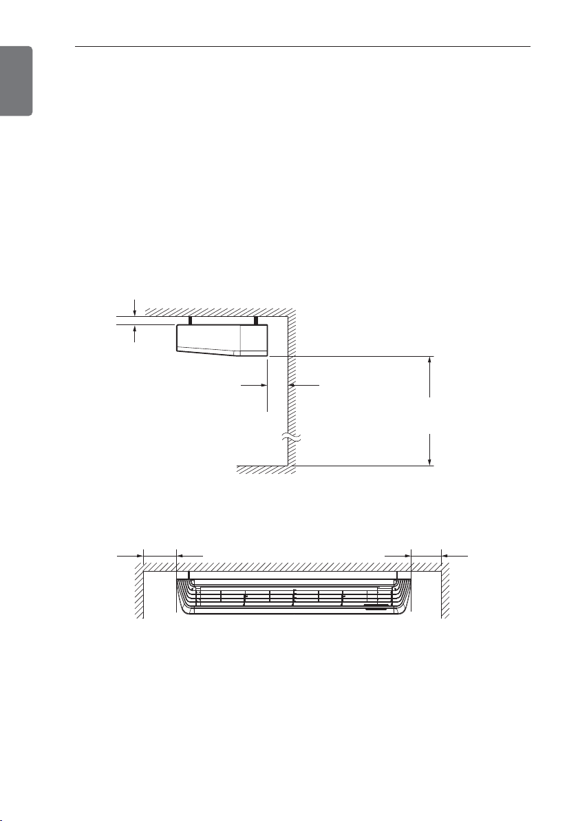
Indoor unit
Ceiling suspended type
- There should not be any heat source or steam near the unit.
- There should not be any obstacles to prevent the air circulation.
- A place where air circulation in the room will be good.
- A place where drainage can be easily obtained.
- A place where noise prevention is taken into consideration.
- Do not install the unit near the door way.
- Ensure the spaces indicated by arrows from the wall, ceiling, or other obstacles.
- The indoor unit must keep the maintenance space.
10 (13/32)
or more
300 (11 – 13/16)
or more
2500 (98 – 3/7)
or more
Floor
700(27 – 9/16) or more 700(27 – 9/16) or more
THE INDOOR UNIT INSTALLATION
7
ENGLISH
THE INDOOR UNIT INSTALLATION
• Install the unit horizontally using a level
gauge.
• During the installation, care should be
taken not to damage electric wires.
• Select and mark the position for fixing
bolts and piping hole.
• Decide the position for fixing bolts
slightly tilted to the drain direction after
considering the direction of drain hose.
• Drill the hole for anchor bolt on the ceiling.
CAUTION
!
NOTE
!
• Avoid the following installation location.
1. Such places as restaurants and kitchen
where considerable amount of oil
steam and flour is generated.
These may cause heat exchange efficiency reduction, or water drops, drain
pump mal-function.
In these cases, take the following actions;
• Make sure that ventilation fan is enough
to cover all noxious gases from this
place.
• Ensure enough distance from the cook-
ing room to install the air conditioner in
such a place where it may not suck oily
steam.
2. Avoid installng air conditioner in such
places where cooking oil or iron powder is generated.
3. Avoid places where inflammable gas is
generated.
4. Avoid place where noxious gas is generated.
5. Avoid places near high frequency generators.
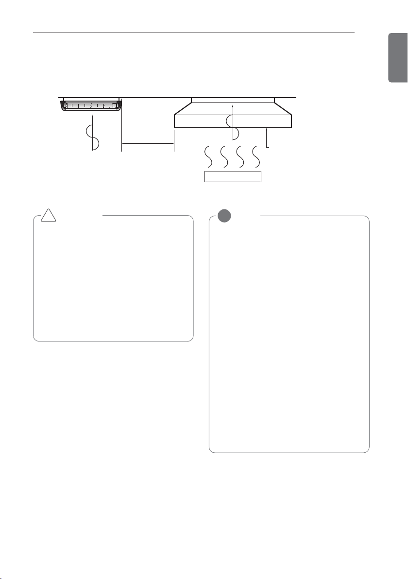
Air conditioner
Take enough
distance
Cooking table
Use the ventilation fan
for smoke-collecting
hood with sufficient
capacity.
8
THE INDOOR UNIT INSTALLATION
ENGLISH
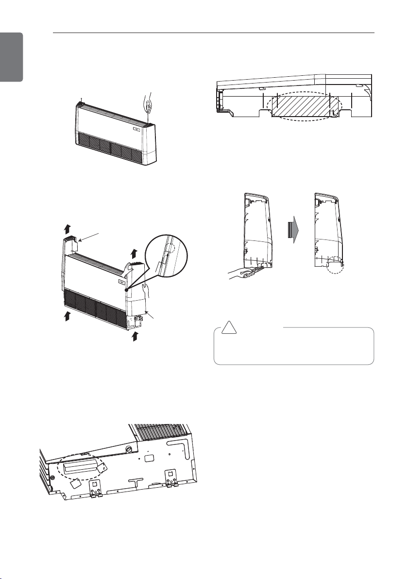
Open side-cover
Step 1
Backside
Right side cover
Backside
Left side
cover
Step 2
Step 5
- Remove two screws from side-cover.
Step 3
Step 4
- Remove bracket from side-panel.
- Remove paper bracket from side-cover.
- Unlock side-cover from side-panel slightly
(Tap the side-cover with your palm on the
backside)
- Knock out the pipe hole from the left sidecover with nipper/plier.
Hold the side-cover with other hand while
tapping to prevent it to fall down.
CAUTION
!
THE INDOOR UNIT INSTALLATION
9
ENGLISH
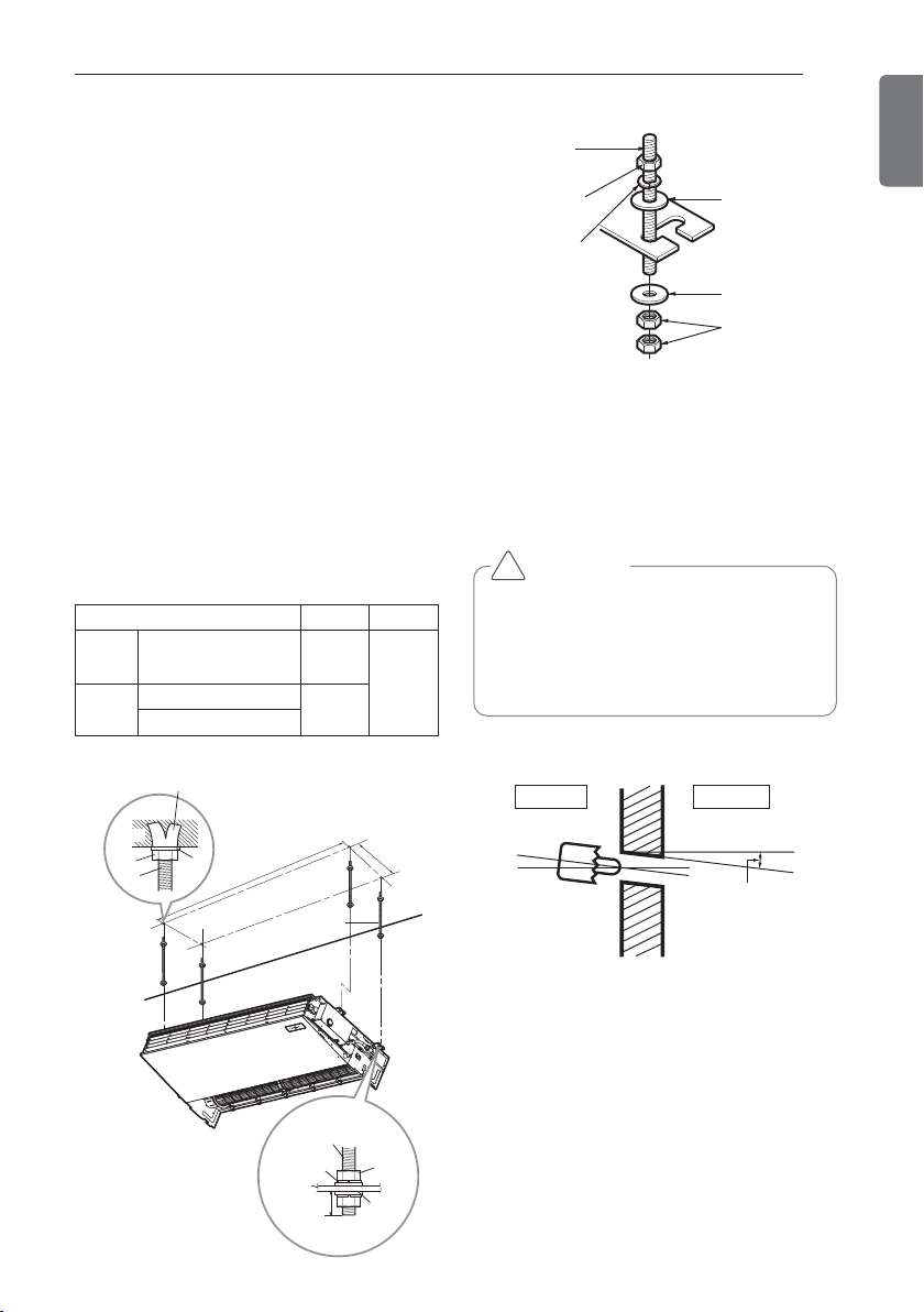
Mounting the anchor nut and bolt
- Prepare 4 suspension bolts. (Each bolts
length should be same.)
- Measure and mark the position for the
Suspension bolts and the piping hole.
- Drill the hole for anchor nut on the ceiling.
- Insert the nuts and washer onto the suspension bolts for locking the suspension bolts on
the ceiling.
- Mount the suspension bolts to the anchornuts firmly.
- Secure the hangers onto the Suspension
bolts (adjust level roughly.) using nuts, washers and spring washers.
- Adjust a level with a level gauge on the
direction of left-right, back-forth by adjusting
suspension bolts.
- Adjust a level on the direction of top-bottom
by adjusting supension bolts. Then the unit
will be declined to the bottomside so as to
drain well.
- The following parts is option.
Hanging Bolt - W 3/8 or M10
Nut - W 3/8 or M10
Spring Washer - M10
Plate Washer - M10
(Unit : mm)
Washer
Suspension
bolts
A B
VM1 AVNQ36GM1A0 1018
355
VM2
AVNQ48GM2A0
1418
AVNQ60GM2A0
Tighten the nut and bolt to prevent unit
from falling
• Drill the piping hole on the wall slightly
tilted to the outdoor side by using a
Ø 70 hole-core drill.
CAUTION
!
Hanging bolt
(W3/8 or M10)
Nut
(W3/8 or M10)
Spring washer
(M10)
Flat washer
for M10
(accessory)
Flat washer
for M10
(accessory)
Nut
(W3/8 or M10)
Anchor nut
Ceiling
Nut
Suspension
Suspension
bolts
bolts
Washer
Washer
A
Suspension bolt
Suspension
bolts
Spring
washer
Hanger
Max.
12mm
B
Nut
Washer
Indoor
Wall
Outdoor
Slope gradient for
drain Should be
1/50 ~ 1/100
10
THE INDOOR UNIT INSTALLATION
ENGLISH
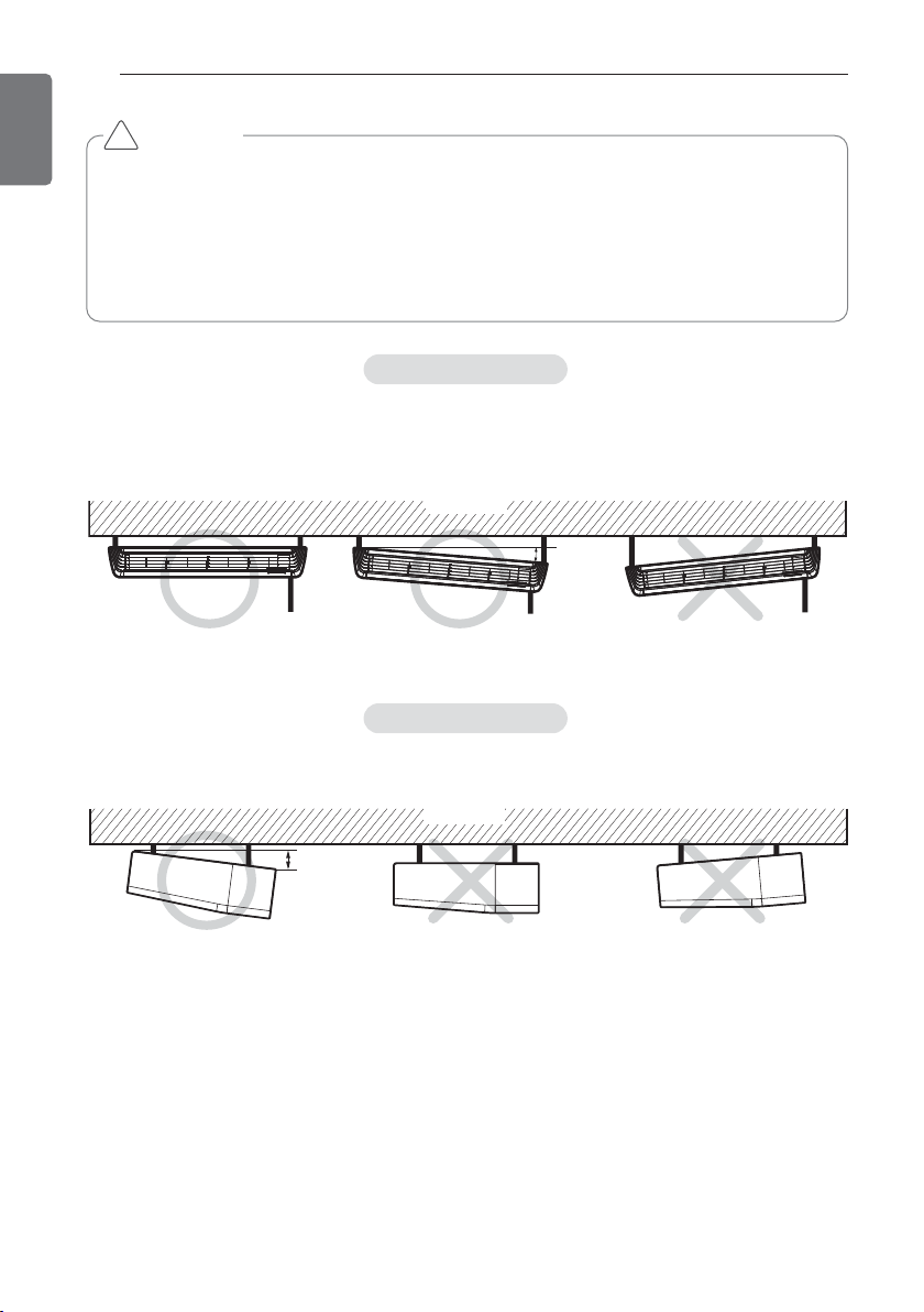
Installation information for declination
- Install declination of the indoor unit is very important for the drain of the convertible type air
conditioner.
- Minimum thickness of the insulation for the connecting pipe shall be 10 mm.
- If the Installation Plates are fixed to horizontal line, the indoor unit after installing will be declined to the bottomside.
CAUTION
!
Front of view
- The unit must be horizontal or inclined at angle.
- The inclination should be less than or equal to 1° or in between 10 to 20 mm inclined in drain
direction as shown in fig.
Ceiling
10~20 mm
Side of view
- The unit must be inclined to the bottomside of the unit when finished installation.
Ceiling
5~10 mm
THE INDOOR UNIT INSTALLATION
11
ENGLISH
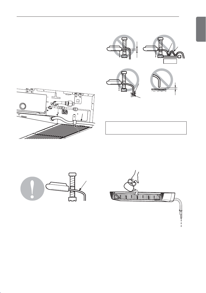
Indoor unit drain piping
- Drain piping must have down-slope (1/50 to
1/100): be sure not to provide up-and-down
slope to prevent reversal flow.
- During drain piping connection, be careful
not to exert extra force on the drain port on
the indoor unit.
- Remove the rubber stopple before connecting drain hose.
- Hook on the bracket after connecting the
drain hose as below.
- Be sure to execute heat insulation on the
drain piping.
Heat insulation material: Polyethylene foam
with thickness more than 8 mm.
Drain piping
- The drain hose should point downward for
easy drain flow.
- Do not make drain piping like the following.
Drain test
Use the following procedure to test the drain
pump operation:
- Set the air direction louvers up-and-down to
the position(horizontally) by hand.
- Pour a glass of water on the evaporator
using a kettle.
- Ensure the water flows through the drain
hose of the indoor unit without any leakage
and goes out the drain exit.
Drain hoseDrain hoseDrain hose
Bracket
Do not raise
Water
leakage
Tip of drain
hose dipped
in water
Water
leakage
Water
leakage
Ditch
Accumulated
drain water
Air
Waving
Less than
50 mm gap
Downward
slope
12
THE INDOOR UNIT INSTALLATION
ENGLISH
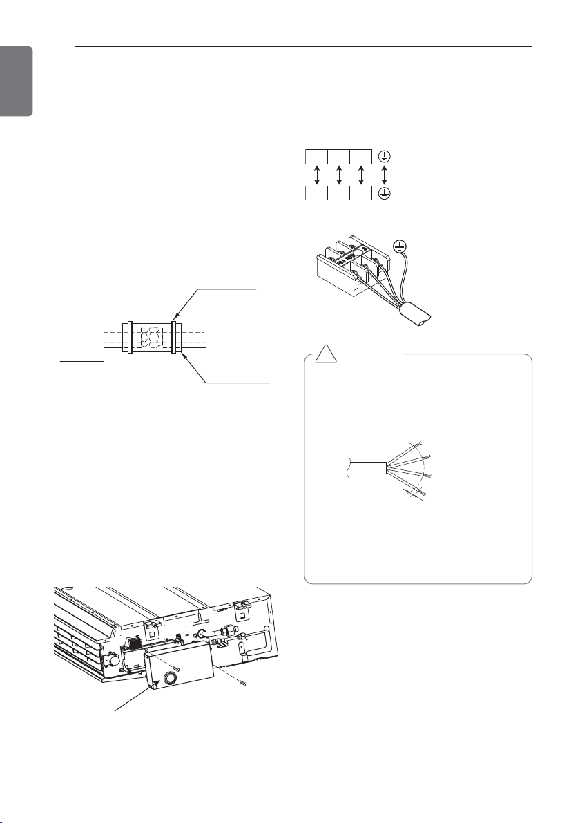
Wiring connection
Connecting cables to the indoor unit
Heat insulation
Use the heat insulation material for the refrigerant piping which has an excellent heat-resistance (over 120 °C).
Precautions in high humidity circumstance:
This air conditioner has been tested according
to the "KS Standard Conditions with Mist" and
confirmed that there is not any default.
However, if it is operated for a long time in
high humid atmosphere (dew point temperature: more than 23 °C), water drops are liable
to fall. In this case, add heat insulation material according to the following procedure:
- Heat insulation material to be prepared...
Adiabatic glass wool with thickness 10 to 20
mm.
- Stick glass wool on all air conditioners that
are located in ceiling atmosphere.
- Remove the control box cover for electrical
connection between the indoor and out door
unit
- Use the cord clamper to fix the cord.
Connect the wires to the terminals on the
control board individually according to the outdoor unit connection.
Control box cover
• The connecting cable connected to the
indoor and outdoor unit should be complied with the following specifications
(Rubber insulation, type H05RN-F approved by HAR or SAA).
• If the supply cord is damaged, it must
be replaced by a special cord or assembly available from the manufacturer of
its service agent.
CAUTION
!
Fastening band
Refrigerant piping
Indoor unit
Thermal insulator
1(L) 2(N) 3
1(L) 2(N) 3
NORMAL
CROSS-SECTIONAL
20
m
m
AREA 0.75 mm
GN
/YL
2
THE INDOOR UNIT INSTALLATION
13
ENGLISH
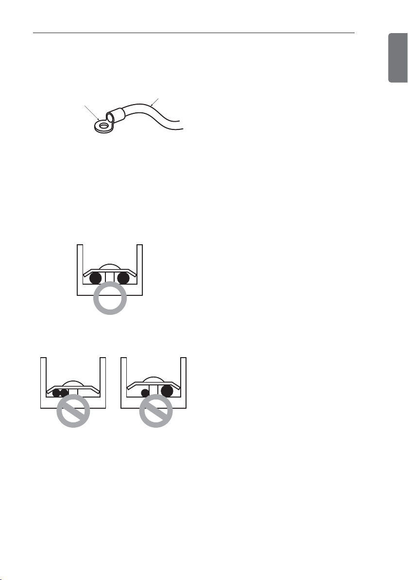
Precautions when laying power wiring
Use round pressure terminals for connections
to the power terminal block.
When none are available, follow the below
instruction
- Do not connect wiring of different thicknesses to the power terminal block. (Slack in the
power wiring may cause abnormal heat.)
- When connecting wiring which is the same
thickness, do as shown in the figure below.
- For wiring, use the designated power wire
and connect firmly, then secure to prevent
outside pressure being exerted on the terminal block.
- Use an appropriate screwdriver for tightening the terminal screws. A screwdriver with
a small head will strip the head and make
proper tighterning impossible.
- Over-tightening the terminal screws may
break them.
Round pressure terminal
Power wire
Connect same thickness
wiring to both sides.
It is forbidden to
connect two to one
side.
It is forbidden to
connect wiring of
different thicknesses.
14
TEST RUNNING
ENGLISH
Connection of power supply
Check the following items when
installation is complete
Precautions in test running
TEST RUNNING
- The initial power supply must provide at
least 90 % of the rated voltage.
Otherwise, the air conditioner should not be
operated.
Connect the power supply cord to the independent power supply.
- Circuit breaker is required.
Operate the unit for 15 minutes or more.
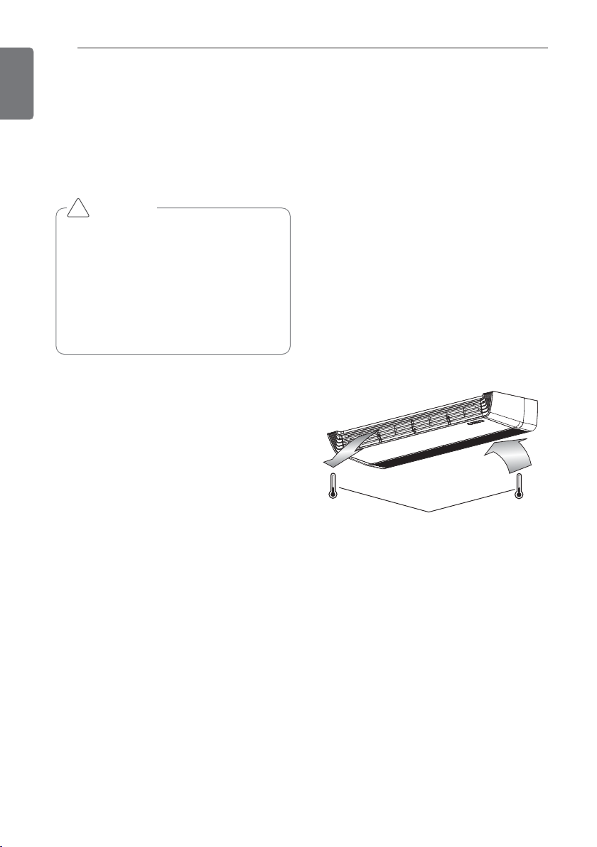
Evaluation of the performance
Measure the temperature of the intake and
discharge air.
Ensure the difference between the intake
temperature and the discharge one is more
than 8 °C (Cooling) or reversely (Heating).
After completing work, be sure to measure
and record trial run properties, and store
measured data, etc.
Measuring items are room temperature, outside temperature, suction temperature, blow
out temperature, wind velocity, wind volume,
voltage, current, presence of abnormal vibration and noise, operating pressure, piping
temperature, compressive pressure.
As to the structure and appearance, check following items.
- Is the circulation of air adequate?
- Is the draining smooth?
- Is the heat insulation completed
(refrigerant and drain piping)?
- Is there any leakage of refrigerant?
- Is the remote controller switch operated?
- Is there any faulty wiring?
- Are not terminal screws loosened?
M4......118 N.cm {12 kgf.cm}
M5......196 N.cm {20 kgf.cm}
M6......245 N.cm {25 kgf.cm}
M8......588 N.cm {60 kgf.cm}
- To cancel the test run, press any button.
• For test run, carry out the cooling operation firstly even during heating season.
If heating operation is carried out firstly,
it leads to the trouble of compressor.
Then attention must be paid.
• Carry out the test run more than 5 minutes without fail.
(Test run will be cancelled 18 minutes
later automatically)
CAUTION
!
Thermometer
TEST RUNNING
15
ENGLISH
Hand over
Teach the customer the operation and maintenance procedures, using the operation manual
(air filter cleaning, temperature control, etc.).
After the confirmation of the above conditions, prepare the wiring as follows:
• Never fail to have an individual power
specialized for the air conditioner. As
for the method of wiring, be guided by
the circuit diagram pasted on the inside
of control box cover.
• Provide a circuit breaker switch between power source and the unit.
• The screw which fasten the wiring in
the casing of electrical fittings are liable
to come loose from vibrations to which
the unit is subjected during the course
of transportation. Check them and
make sure that they are all tightly fastened. (If they are loose, it could give
rise to burnout of the wires.)
• Specification of power source.
• Confirm that electrical capacity is sufficient.
• Be sure that the starting voltage is
maintained at more than 90 percent of
the rated voltage marked on the name
plate.
• Confirm that the cable thickness is as
specified in the power sources specification.
(Particularly note the relation between
cable length and thickness.)
• Never fail to equip a leakage breaker
where it is wet or moist.
• The following troubles would be caused
by voltage drop-down.
- Vibration of a magnetic switch, damage on the contact point there of, fuse
breaking, disturbance to the normal
function of a overload protection device.
- Proper starting power is not given to
the compressor.
• Use only 1 remote-controller contained
in indoor unit, when you combine to
use both ceiling suspended type indoor
unit and different Indoor units combinations.
CAUTION
!
16
INSTALLATION INSTRUCTIONS
ENGLISH
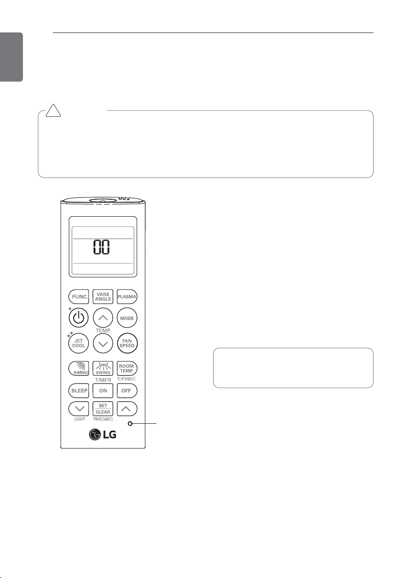
1 With the JET COOL button pressed, press
the RESET button.
2 By using the TEMPERATURE SETTING
button, set function code and setting
value. (Please refer the Intaller setting
code table.)
3 Press the ON/OFF button toward the
indoor unit 1 time.
4 Reset the remote controller to use the
general operation mode.
CAUTION
Installer setting mode is to set the detail function of the remote controller.
If the installer setting mode is not set correctly, it can cause problems to the product, user
injury or property damage. This must be set by an certificated installer, and any installation
or change that is carried out by a non-certificated person should be responsible for the
results. In this case, free service cannot be provided.
!
Refer to the Intaller setting code table
on the next page.
INSTALLATION INSTRUCTIONS
Installer setting - how to enter installer setting mode
RESET
INSTALLATION INSTRUCTIONS
17
ENGLISH
Mode override
This function is only for Non-Auto changeover H/P model.
Ceiling height selection
Indoor unit connected to wired remote controller operate as wired remote controller setting.
only for ceiling cassette type.
Group control (optional)
This function is only for group control. Please don’t set this function in case of non-group
control.
After setting group control of the product, turn off the power then turn it back on after 1
minute.
Auxiliary heater
This function is only applied to models with auxiliary heater function being activated.
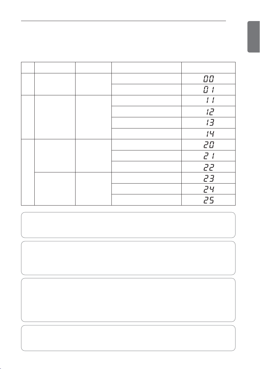
No. Function Function code Setting value Remote controller LCD
0 Mode override
0
0 : Set to master
1 : Set to slave
1
Ceiling height
Selection
1
1 : Standard
2 : Low
3 : High
4 : Super high
2
Group control
2
0 : Set to master
1 : Set to slave
2 : Check master/slave
Auxiliary heater
2
3 : Set to auxiliary heater
4 : Cancel auxiliary heater
5 :
Check auxiliary heater Installation
Installer setting code table
Installer setting - installer setting code table
 Loading...