

LG AVNH246BLAC, AVNH186BLAC, AVNH306BLAC, AVNH366KLAC, AVNH486LLAC Service Manual
...
LG
Universal System
Air Conditioner
SERVICE MANUAL
LG
CAUTION
website http://www.lgservice.com
e-mail http://www.lgeservice.com/techsup.html
• BEFORE SERVICING THE UNIT, READ THE SAFETY
PRECAUTIONS IN THIS MANUAL.
• ONLY FOR AUTHORIZED SERVICE PERSONNEL.

2 Universal System Air Conditioner
TABLE OF CONTENTS
Safety Precautions ...................................................................................................3
I. Indoor Units
Introduction..............................................................................................................8
Ceiling Cassette 4-way..........................................................................................10
Ceiling & Floor .......................................................................................................37
Ceiling concealed Duct..........................................................................................54
II. Outdoor Units
Introduction............................................................................................................76
MPS Variable Single A(AUUH-C, R410A) .............................................................78
III. Troubleshooting Guide
Self-diagnosis Function .......................................................................................102
Electronic Parts Troubleshooting Guide ..............................................................103
IV. Electronic Control Device
Ceiling Cassette Type..........................................................................................110
Ceiling Duct Type.................................................................................................111
Ceiling & Floor .....................................................................................................113
V. Schematic Diagram
Ceiling Cassette Type..........................................................................................116
Ceiling Duct Type.................................................................................................117
Ceiling & Floor .....................................................................................................118
VI. Functional Description
Ceiling Cassette Type..........................................................................................120
Ceiling Duct Type.................................................................................................122
Ceiling & Floor .....................................................................................................125
Outdoor Units ......................................................................................................128
VII. Explode View and Replacement Parts List
Indoor Units .........................................................................................................140
Outdoor Units ......................................................................................................150
Panel Assembly, Front .........................................................................................173

I. Indoor Units
Introduction.......................................................................................................8
Ceiling Cassette 4-way...................................................................................10
Ceiling & Floor ................................................................................................37
Ceiling Concealed Duct..................................................................................54
Service Manual 7
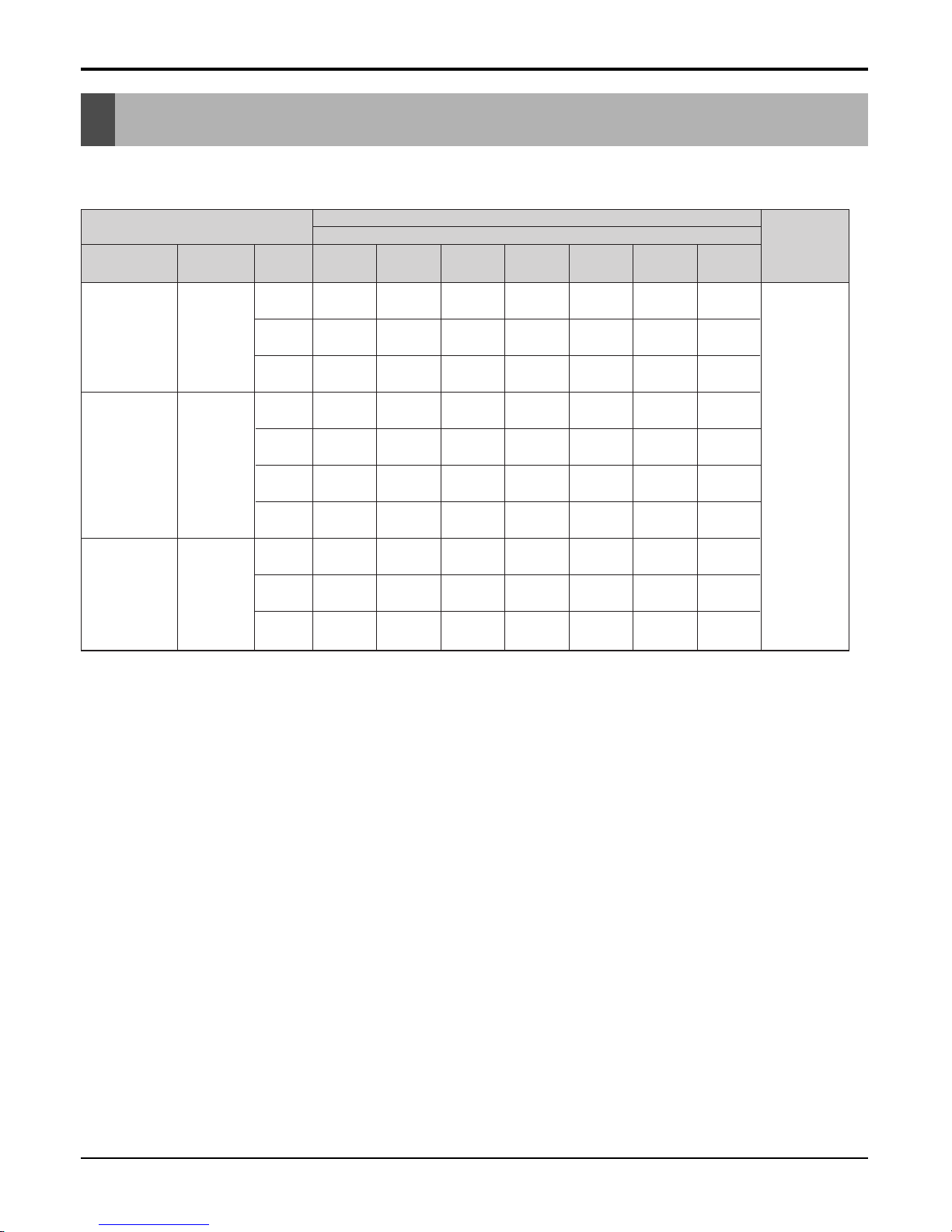
• Models List
Type Refrigerant
Chassis
name
18,000
(5.3)
24,000
(7.0)
30,000
(8.8)
36,000
(10.6)
TE
ATNH
186ELFC
---
TF
-
ATNH
246FLFC
ATNH
306FLFC
-
TD
-- -
ATNH
366DLFC
Ceiling & Floor R410A
VB
VK
VL
AVNH
186BLAC
AVNH
246BLAC
AVNH
306BLAC
AVNH
366KLAC
AVNH
486LLAC
AVNH
606LLAC
-
BH
ABNH
186HLAC
ABNH
246HLAC
--
-
BG
-
12,000
(3.5)
ATNH
126ELFC
-
-
-- --
-- --
-
-
--
BR
-----
ABNH
306GLAC
48,000
(14.1)
-
--
ATNH
486DLFC
ATNH
606DLFC
-
60,000
(17.6)
-
-
--
--
--
VE
AVNH
126ELAC
-
-
--
--
ABNH
486RLAC
ABNH
606RLAC
ABNH
366GLAC
1Ø, 220-240V,
50Hz
Model name
Nominal capacity [Btu/h(kW)]
Power
Supply
R410A
Ceiling
Cassette
4-Way
Ceiling
Concealed
Duct
Indoor unit
R410A
8 Universal System Air Conditioner
Introduction
Introduction
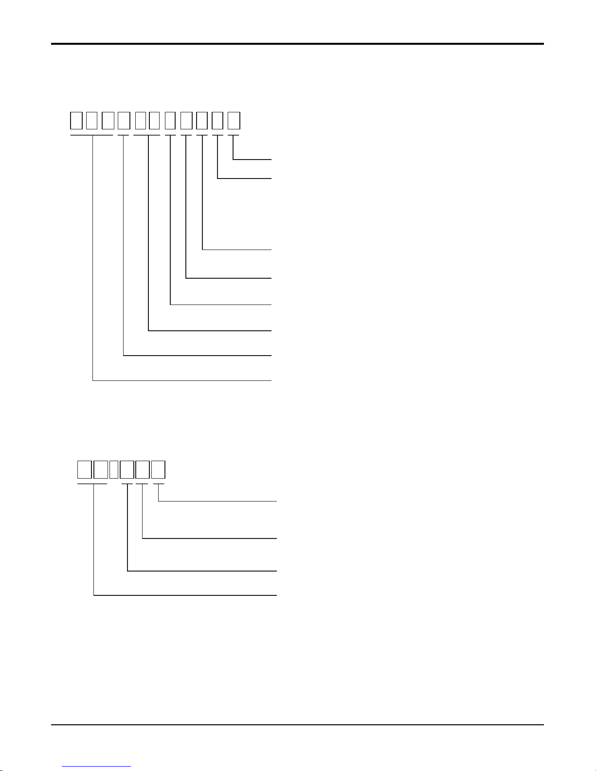
• Model Number Nomenclature
Indoor unit
Decoration panel(For Ceiling Cassette Models)
A T N H 1 8 6 E L FC
Serial Number
Functions
A : Basic B : Low Ambient
C : Plasma Filter E : Elevation Grille
F : Elevation Grille + Plasma Filter
H : Plasma Filter + Low Ambient
L : Nano Plasma M : Nano Plasma + Elevation Grille
Look
L : Basic
E : E Chassis F : F Chassis D : D Chassis
Chassis Name
Electrical Ratings
6:1Ø,220V~240V,50Hz 8:3Ø,380V~415V,50Hz
Nominal Cooling Capacity in Btu/h
Ex) 18 -> 18,000 Btu/h, 48 -> 48,000 Btu/h
Model Type
C : Cooling Only H : Heat Pump
Indicates that this is a indoor unit for R410A
ATN : Ceiling cassette type indoor unit
ABN : Ceiling concealed duct type indoor unit
AVN : Convertible type indoor unit
P T - H EC
Functions
A : Basic C : Plasma Air Purifier
E : Elevation Grille F : Elevation Grille + Plasma Air Purifier
Indoor Unit Chassis
E : E Chassis F : F Chassis D : D Chassis
Model Type
C : Cooling Only H : Heat Pump
Decoration Panel of Ceiling Cassette Type Indoor Unit
Service Manual 9
Introduction
10 Universal System Air Conditioner
Ceiling Cassette 4-way
Contents
1. Features & Benefits ..............................................................................11
2. List of Functions....................................................................................15
3. Specifications........................................................................................16
4. Dimensional Drawings ..........................................................................18
5. Wiring Diagrams ...................................................................................22
6. Piping Diagrams....................................................................................24
7. Operating Instructions...........................................................................25
8. Installation.............................................................................................29
9. Accessories ..........................................................................................36
Ceiling Cassette 4-way
(R410A·Indoor Units)
ATNH-EL/FL/DL
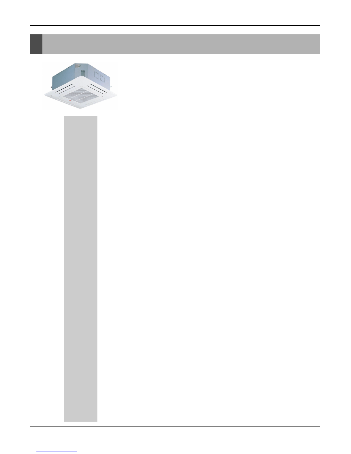
Ceiling Cassette 4-way

(18k Btu/h model)
■ Convenience
• Auto elevation grille(Accessory)
• Tele control(Accessory)
• LCD wired remote control
• Group control
• Central control(Accessory)
• Weekly progam
■ Cleanness
• Plasma air purifying system
• Hygienic and easy to clean filter
■ Easy Installation
• Compact design & easy installation
• High ceiling corresponding operation
• High head drain pump(700mm)
■ Comfort & Reliability
• Low noise with 3-dimensional turbo fan
• 2-Thermistor control(Main body & Remote control)
• Zero stanby power consumption
• Jet cool
• Swirl swing
• Space control
Compact Design and Easy Installation
Only about 269mm height in the ceiling is sufficient for
installation space.
A smaller size than a Textile(600X600) is very convenient for installation.
Low Noise with 3-dimensional
turbo fan
The most advanced low-noise design.
The adoption of turbo-fan and round type heat
exchanger provides the quietest operation.
Hygienic and Easy-to-Clean Filter
Washable and anti bacteria filter is adopted.
It is easy to open grille and replace clean filter.
Service Manual 11
Ceiling Cassette 4-way
1. Features & Benefits
12 Universal System Air Conditioner
Ceiling Cassette 4-way
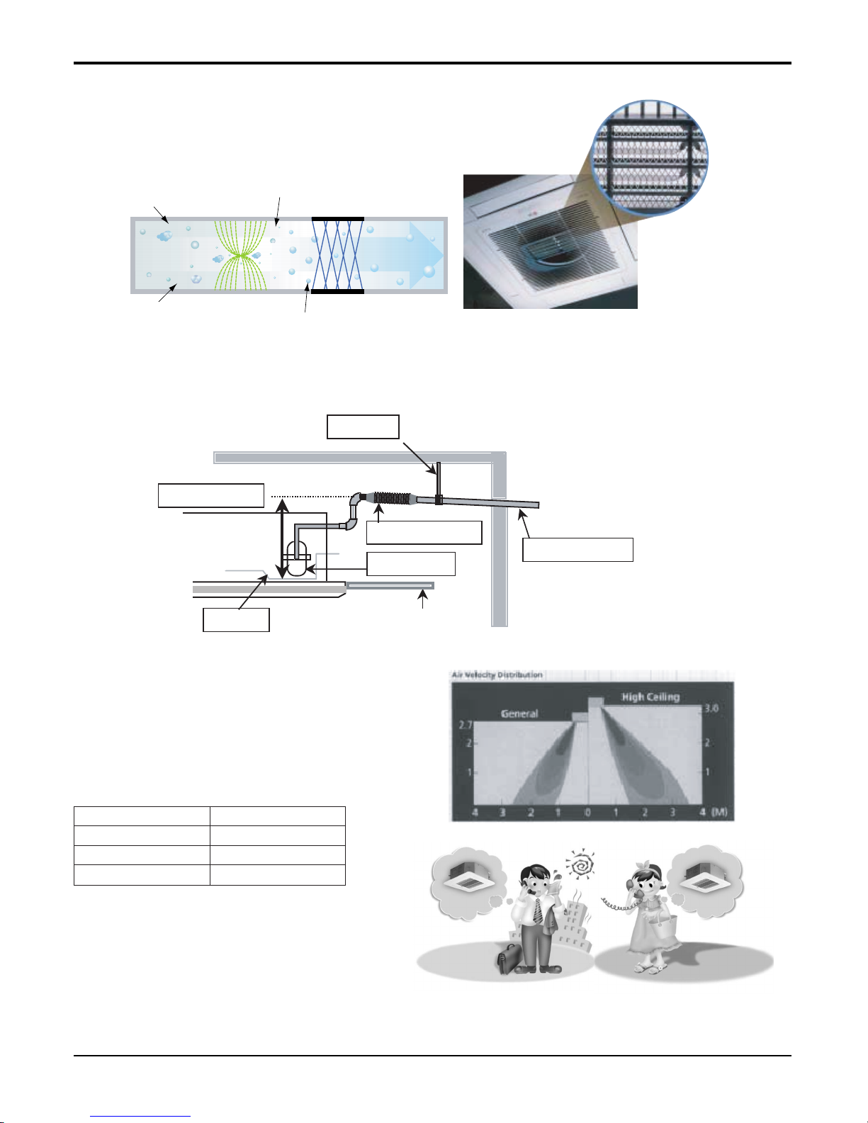
Ceiling Board
Drain Pan
Maximum 700mm
Drain Pump
Flexible drain hose
Pipe fixture
Slope 1/50~1/100
Hard Tube(ex.PVC)
+
+
+
+
Polluted Air
Purified fresh Air
+4.8KV discharge
Ionizer Photo-Catalyst Coated Mesh
Dust particles
Odour
Dust electrode discharge
Odour molecule
Generating plasma
Plasma Air Purifying System
The PLASMA Air Purifying Function not only removes microscopic contaminants and dust, but also removes house
mites, pollen, and pet fur helps to prevent allergic diseases
like asthma.
High Head Drain Pump(700mm)
Built-in Drain Pump drains out water automatically.
A standard drain-head height of up to 700 mm is possible, creating the ideal solution for perfect water drainage.
High-Ceiling Corresponding Operation
According to the height of the installation, it provides variability of indoor fan motor rpm. If the height of installation is
low then you can adjust low rpm of indoor fan motor. On
the other hand if the height of the installation is high you
can adjust high rpm of indoor fan motor. Selection of
speed can be done by slide switch at the back of the LCD
wired remote.
Tele Control (Accessory)
- It provides you ease of control. Air conditioner
can be switched on/off by the telephone. It
saves time & energy.
ON
ONON OFF
OFF
OFFOFF
In Advance by Telephone
Before Coming Home...
In case of Going out
Without Turning off the
Air Conditioner...
Over than 3.3mHigh Ceiling
2.7~3.3mStandard
Ceiling HeightSwitch selection
Less than 2.7mLow Ceiling
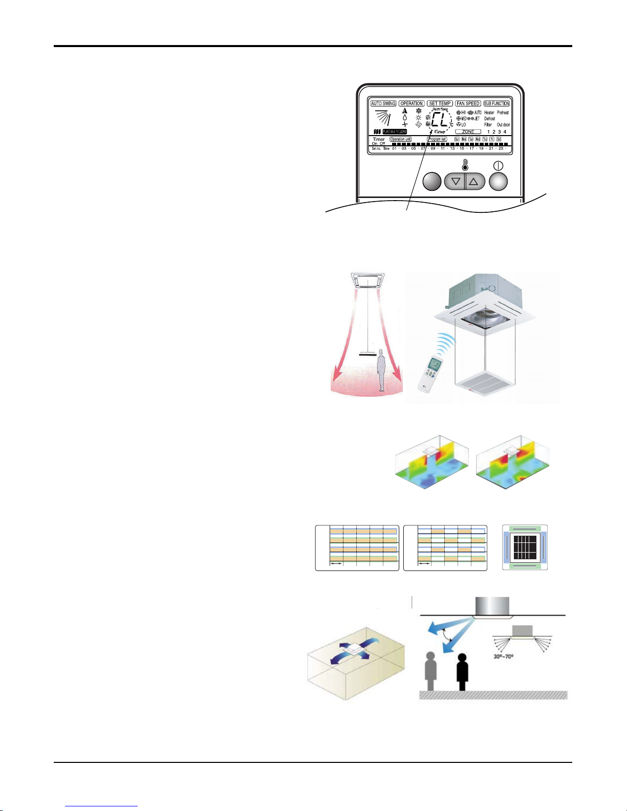
Child Lock Function
-It prevents the children or others from tampering
with the control buttons. Unit can be controlled by
the wireless remote controller. This can be easily set
by pressing timer key & Min key simultaneously.
After child lock is set, pressing any key will display
CL on the LCD for 3 seconds and all the keys will be
ineffective.
Auto Elevation Grille(Accessory)
-Auto Elevation Grille is automatically down to height
of max. 3.1 m. So it enables to install the Indoor unit
at high ceiling space. And Auto Elevation Grille
makes you cleaning the filter easily.
CHILD LOCK
-Display
71
Vane 2
Swirl Swing(New)4- Open(Conventional)
Swirl Swing(New)4- Open(Conventional)
2.4% 4.8%100% Improved
Comparison of Air Flow Types
Comparison of Floor
Temp. Distribution(20°C)
Vane 1 Close OpenOpen
Open
Open
Open
Close CloseOpen
Vane 3 Close Open Close CloseOpen
OpenOpen Close CloseOpen
Vane 2
OpenOpen
Time
Close CloseOpen
Vane 4
Vane 1
Vane 3
Vane 2
Time
Vane 4
Vane 3
Vane 4
Vane 1
Swirl Swing
- It is the function for comfort cooling/heating operation.
- The diagonal two louvers are opened the
more larger than the other louvers.
After one minute, it is opposite.
Space Control
Vanes angle can be controlled by pair, considering its
installation environment.
- For example direct drafts can be annoying, leading
to discomfort and reduced productivity vane control
helps to eliminate this problem.
- Easily controlled by wired remote control.
- Air Flow can be controlled easily regarding any
space environment.
Service Manual 13
Ceiling Cassette 4-way
14 Universal System Air Conditioner
Ceiling Cassette 4-way
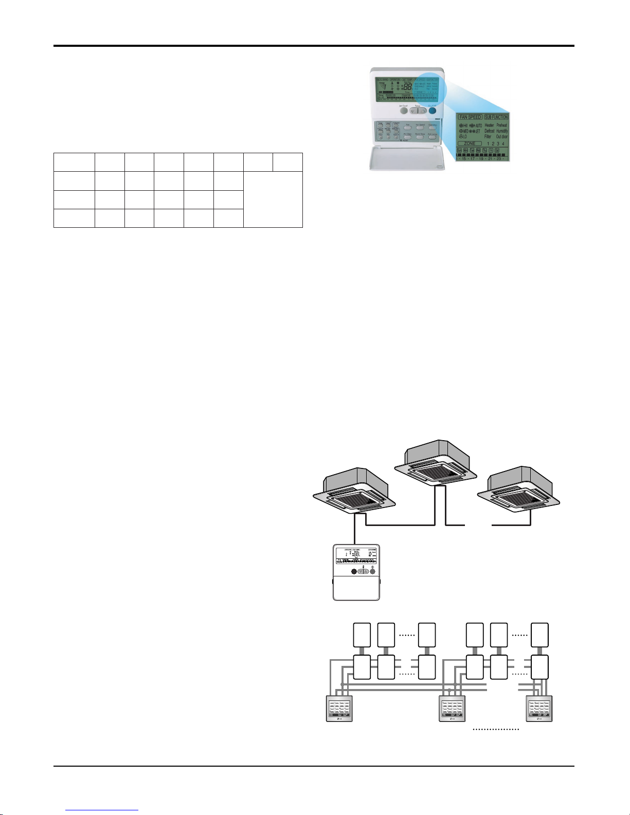
Weekly Program
- On/Off schedule of operation for a period of ONE
week.
No need to turn the unit On/OFF manually during
working days. On/Off time is scheduled in micom of
the wired remote control.
Auto Restart Operation
- Whenever there is electricity failure to the unit, and after resumption of the power, unit will start in the same
mode prior to the power failure. Memorized condition are on / off condition, operating mode (cooling/heating),
set temperature and fan speed.The unit will memorize the above conditions and start with same memorized
condition.
Two Thermistor Control
- There may be a significant difference between the temperature taken at the installed product and indoor temperature. Two thermistor control provides option to control temperature by referring any of the two temperatures. With the help of the slide switch at the back of the LCD wired remote controller, selection of the desired
thermistor for controlling the unit can be done. One thermistor is in the Indoor unit & the other one is in the
LCD wired remote.
Group Control
- It enables to control as much as 16 units with the
help of one wired remote controller. All the units will
follow same setting of temperature & other sub functions.
Central Control(Accessory)
- It enables to control 16 x 8 = 128 units with the help
of 8 controllers. All units can be put on and off from
one Central Room.For Setting Temperature, Fan
Speed and other sub functions, access the respective LCD wired remote controller of each unit.
❈ Sub PI485(with wire assembly) should be pur-
chased as optional.
Operation Time Table (Example)
Mon Tue Wed Thu Fri Sat Sun
OFF
Setting
Temp.
On
Off
25°C25°C25°C25°C25°C
09:00
12:00
08:00
17:00
09:00
12:00
08:00
12:00
09:00
12:00
10mm 10mm
12 16........
........
Main
PCB
Controller
# 1
Controller
# 2
Controller
# 8
M
1
Sub
1
M
2
Sub
2
M
16
Sub
16
M
17
Sub
17
M
18
Sub
18
M
128
Sub
128
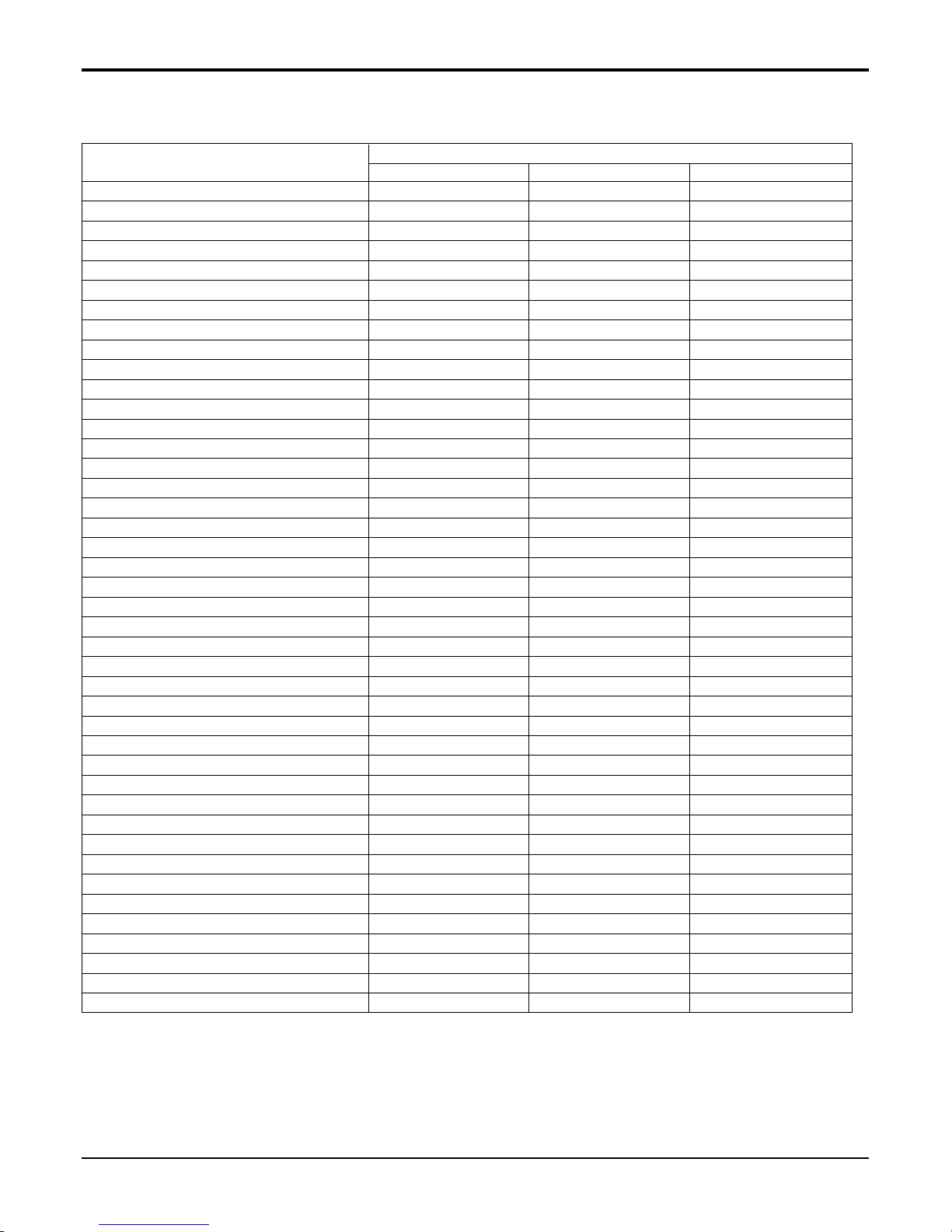
Air Discharge Outlet 4 4 4
Airflow Direction control (left & right) - - Airflow Direction control (up & down) Auto Auto Auto
Airflow Steps(Fan / Cool /Heat) 3/4/3 3/4/3 3/4/3
Auto Changeover O O O
Auto Elevation Grille Accessory Accessory Accessory
Auto Operation O O O
Auto Restart Operation O O O
Auto Swing O O O
Central Control Accessory Accessory Accessory
CHAOS Wind (Auto wind) - - Child Lock Function O O O
Cooling & Fan Operation(Cooling Only) - - Cooling, heating & Fan Operation(Heat Pump) O O O
Defrost / Deicing O O O
Deodorizing Filter - - Drain Pump O O O
E.S.P. Control - - Electric Heater - - Environment Friendly Refrigerant O O O
Fire Alarm Function - - Forced Operation O O O
Group Control O O O
High Ceiling Operation O O O
Hot Start O O O
Jet Cool O O O
Plasma Air Purifier O O O
Prefilter(Washable / Anti-fungus) O O O
Self Diagnosis O O O
Sleep Mode O O O
Soft Dry Operation O O O
Swirl Swing O O O
Space Control O O O
Tele Control Accessory Accessory Accessory
Temperature Control O O O
Test Function O O O
Time Delay Safety function O O O
Timer (weekly) O O O
Two Thermistor Control O O O
Wired LCD Remote Control O O O
Wireless Remote Control Accessory Accessory Accessory
Zero Standby Power O O O
ATNH-EL ATNH-FL ATNH-DL
Ceiling Cassette-4way
Function
Notes :
O : Basic
Optional : Factory-Installed
Accessory : Field-Installed
- : Not available on this system
Service Manual 15
Ceiling Cassette 4-way
2. List of Functions
16 Universal System Air Conditioner
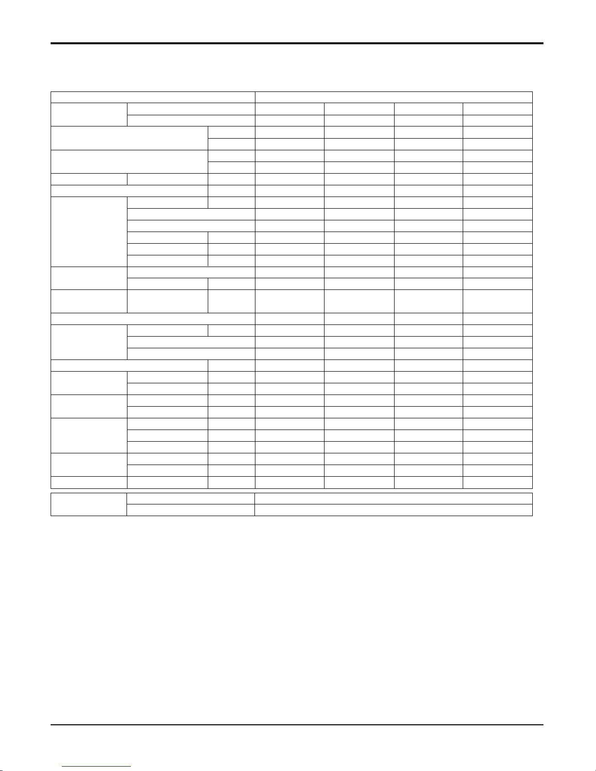
Ceiling Cassette 4-way
Nominal Cooling Capacity kcal/h(W)
Btu/h
Nominal Heating Capacity kcal/h(W)
Btu/h
Air Circulation H/M/L CMM(CFM)
Setting temperature range(cool/heat) °C
Fan motor Output W
Model
No. of Poles
Input W
Running Current A
Capacitor µF/Vac
Fan Type
No. Used / Diameter
EA/inch(mm)
Noise Level
H/M/L dB(A)
(Sound Press,1.5m)
Temperature controller
Coil Tube Size (OD) inch(mm)
Fins per inch
No. of Rows & Column
Dehumidification Rate l/h
Dimensions Indoor Unit inch(mm)
(W*H*D) Decoration Panel inch(mm)
Net Weight Indoor Unit kg(lbs)
Decoration Panel kg(lbs)
Piping Connection Liquid inch(mm)
Gas inch(mm)
Drain hose (ID Ø) inch(mm)
Packing Dimension Indoor Unit inch(mm)
(W*H*D) Decoration Panel inch(mm)
Stuffing Quantity Without S/Parts 20/40ft
Indoor Unit Type Ceiling Cassette 4-way
Model Indoor Unit ATNH126ELFC ATNH186ELFC ATNH246FLFC ATNH306FLFC
Decoration Panel PT-HEC(F) PT-HEC(F) PT-HFC(F) PT-HFC(F)
Notes:
1. Capacities are based on the following conditions:
Cooling: - Indoor Temperature 27°C(80.6°F) DB /19°C(66.2°F) WB
- Outdoor Temperature 35°C(95°F) DB /24°C(75.2°F) WB
- Interconnecting Piping Length 7.5m
- Level Difference of Zero.
Heating: - Indoor Temperature 20°C(68°F) DB / 15°C(59°F) WB
- Outdoor Temperature 7°C(44.6°F) DB / 6°C(42.8°F) WB
- Interconnecting Piping Length 7.5 m
- Level Difference of Zero.
2. Capacities are Net Capacities.
3. Due to our policy of innovation some specifications may be changed without notification.
For outdoor units Single Split
See chapter MPS Variable SINGLE-A(AUUH-B)
Application Split(Simultaneous operation)
See chapter MPS Variable SINGLE-A(AUUH-B)
3024(3517) 4536(5275) 6048(7033) 7560(8793)
12000 18000 24000 30000
3326(3869) 4990(5803) 6653(7738) 8316(9672)
13200 19800 26400 33000
9.5/8/7(336/283/247) 13/12/11(459/424/388) 15/14/13(523/494/459) 19/17/15(671/600/530)
18~30 / 16~30 18~30 / 16~30 18~30 / 16~30 18~30 / 16~30
18.3 22.4 40.3 48.6
IC-9630LGAE IC-9630LGAC OBM-350292 OBM-4015P2
6666
75 90 121 146
0.35 0.43 0.53 0.67
2.5/440 2.5/440 4/440 4/440
Turbo Fan Turbo Fan Turbo Fan Turbo Fan
1/13.0(330) 1/13.0(330) 1/15.0(382) 1/15.0(382)
38 / 35 / 32 41/39/37 43/41/39 45/42/39
Thermistor Thermistor Thermistor Thermistor
0.275(7) 0.275(7) 0.275(7) 0.275(7)
19 19 21 21
2R,11C 2R11C 2R12C 2R12C
1.2 2.4 3 3.3
22.4*10.5*22.4(570*269*570) 22.4*10.5*22.4 (570*269*570) 29.3*11.5*29.4 (744*292*744) 29.3*11.5*29.3(744*292*744)
26.4*1.2*26.4(670*30*670) 26.4*1.2 *26.4(670*30*670) 33.5*1.2 *33.5(850*30*850) 33.5*1.2*33.5(850*30*850)
19(41.9) 19(41.9) 24(52.9) 24(52.9)
3(6.6) 3(6.6) 3(6.6) 3(6.6)
1/4 (6.35) 1/4 (6.35) 1/4 (6.35) 1/4 (6.35)
3/8 (9.52) 1/2 (12.7) 1/2 (12.7) 5/8 (15.88)
1.26(32) 1.26(32) 1.26(32) 1.26(32)
25.2*13.0*25.2(640*330*640) 25.2*13.0*25.2(640*330*640) 32.6*14.4*32.6(828*365*828) 32.6*14.4*32.6(828*365*828)
29.5*3.1*29.5(750*80*750) 29.5*3.1*29.5(750*80*750)
36.8*3.5*36.8(935*90*935) 36.8*3.5*36.8(935*90*935)
189/378 189/378 84/168 84/168
3. Specifications

Service Manual 17
Ceiling Cassette 4-way
Nominal Cooling Capacity kcal/h(W)
Btu/h
Nominal Heating Capacity kcal/h(W)
Btu/h
Air Circulation H/M/L CMM(CFM)
Setting temperature range(cool/heat) °C
Fan motor Output W
Model
No. of Poles
Input W
Running Current A
Capacitor µF/Vac
Fan Type
No. Used / Diameter
EA/inch(mm)
Noise Level
H/M/L dB(A)
(Sound Press,1.5m)
Temperature controller
Coil Tube Size (OD) inch(mm)
Fins per inch
No. of Rows & Column
Dehumidification Rate l/h
Dimensions Indoor Unit inch(mm)
(W*H*D) Decoration Panel inch(mm)
Net Weight Indoor Unit kg(lbs)
Decoration Panel kg(lbs)
Piping Connection Liquid inch(mm)
Gas inch(mm)
Drain hose (ID Ø) inch(mm)
Packing Dimension Indoor Unit inch(mm)
(W*H*D) Decoration Panel inch(mm)
Stuffing Quantity Without S/Parts 20/40ft
Indoor Unit Type Ceiling Cassette 4-way
Model Indoor Unit ATNH366DLFC ATNH486DLFC ATNH606DLFC
Decoration Panel PT-HDC(F) PT-HDC(F) PT-HDC(F)
9072(10549) 12095(14067) 14112(16412)
36000 48000 56000
9979(11607) 13305(15474) 15523(18053)
39600 52800 61600
25/23/21(883/812/742) 30/28/26(1059/988/918) 34/32/30(1200/1130/1059)
18~30 / 16~30 18~30/16~30 18~30/16~30
52.5 58.5 107
IC-1630LGPJ IC-1640LGPH IC-14640LGPM
666
175 195 237
0.76 1.5 1.8
4/440 6/400 6/400
Turbo Fan Turbo Fan Turbo Fan
1/18.1(460) 1/18.1(460) 1/18.1(460)
40/38/36 43/41/39 50/47/43
Thermistor Thermistor Thermistor
0.275(7) 0.275(7) 0.275(7)
21 21 21
2R12C 2R12C 2R12C
4.0 5.5 6.5
33.1*11.3*33.1(840*288*840) 33.1*11.3*33.1(840*288*840) 33.1*11.3*33.1(840*288*840)
37.4*1.2*37.4(950*30*950) 37.4*1.2*37.4(950*30*950) 37.4*1.2*37.4(950*30*950)
32(70.4) 32(70.4) 32(70.4)
5(11) 5(11) 5(11)
1/4 (6.35) 3/8(9.52) 3/8(9.52)
5/8 (15.88) 3/4(19.05) 3/4(19.05)
1.26(32) 1.26(32) 1.26(32)
36.4*13.8*36.4(925*350*925) 36.4*13.8*36.4(925*350*925) 36.4*13.8*36.4(925*350*925)
40.6*3.5*40.6(1,030*90*1,030) 40.6*3.5*40.6(1,030*90*1,030) 40.6*3.5*40.6(1,030*90*1,030)
72/144 72/144 72/144
Notes:
1. Capacities are based on the following conditions:
Cooling: - Indoor Temperature 27°C(80.6°F) DB /19°C(66.2°F) WB
- Outdoor Temperature 35°C(95°F) DB /24°C(75.2°F) WB
- Interconnecting Piping Length 7.5m
- Level Difference of Zero.
Heating: - Indoor Temperature 20°C(68°F) DB / 15°C(59°F) WB
- Outdoor Temperature 7°C(44.6°F) DB / 6°C(42.8°F) WB
- Interconnecting Piping Length 7.5 m
- Level Difference of Zero.
2. Capacities are Net Capacities.
3. Due to our policy of innovation some specifications may be changed without notification.
For outdoor units Single Split
See chapter MPS Variable SINGLE-A(AUUH-B)
Application Split(Simultaneous operation)
See chapter MPS Variable SINGLE-A(AUUH-B)
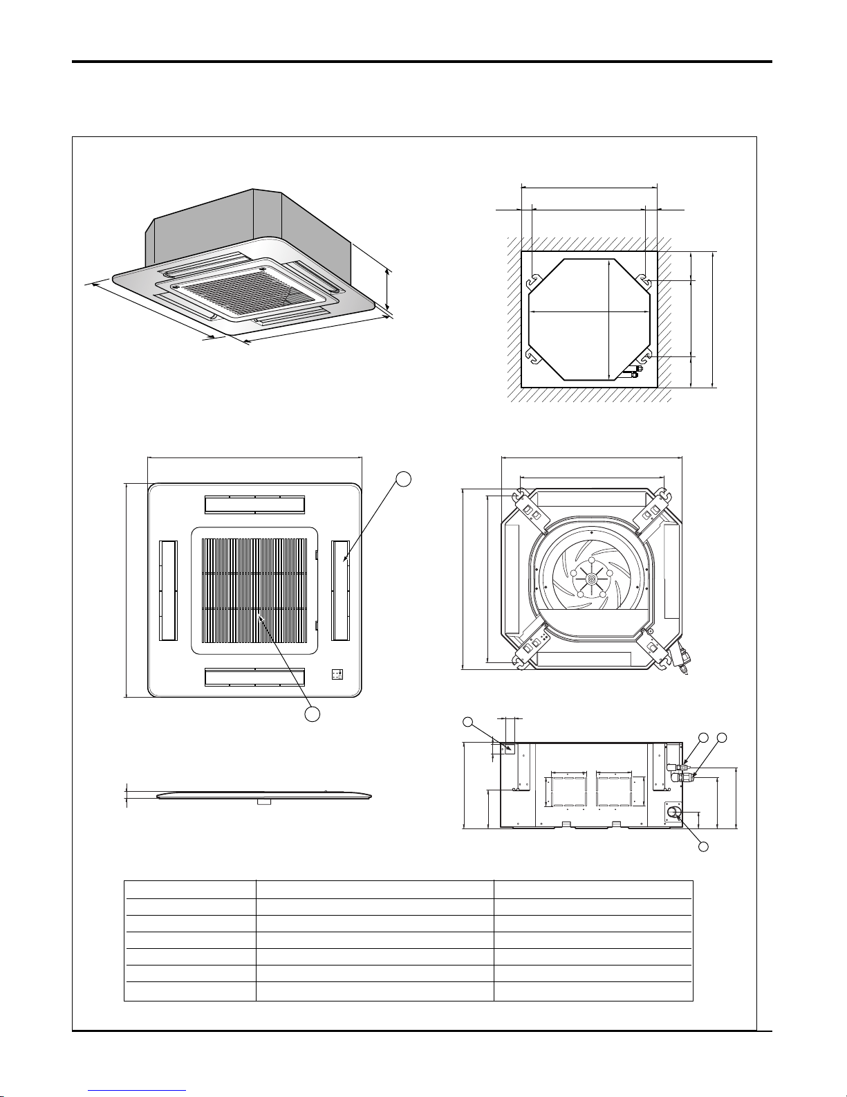
18 Universal System Air Conditioner
Ceiling Cassette 4-way
269
570
269
190.5
160
52
90
90
120.4
30
521
570
450
40
110 110
670
670
4
132
Unit:mm
570 Unit size
570 Unit size
450 (Hanging bolt)
7575
600 (Ceiling opening)
600 (Ceiling opening)
521(Hanging bolt)
39.5
39.5
670
670
5
6
30
ATNH-EL
(unit : mm)
Number Name Descripition
1 Liquid pipe connection ø6.35 flare
2 Gas pipe connection 12k: ø9.52, 18k:
ø12.7 flare
3 Drain pipe connection
4 Power supply connection
5 Air discharge grille
6 Air suction grille
4. Dimensional Drawings
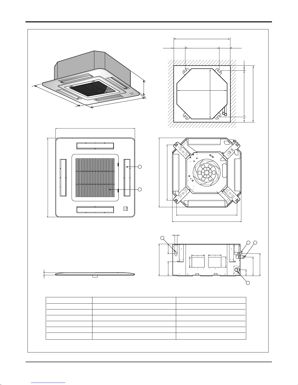
Service Manual 19
Ceiling Cassette 4-way
292
850
850
850
850
744
658
572
744
292
212
150
54
90
90
192 117
70
110 110
4
132
5
6
Unit:mm
744 Unit size
744 Unit size
658 (Hanging bolt)
6666
790 (Ceiling opening)
790 (Ceiling opening)
572(Hanging bolt)
109
109
30
ATNH-FL
(unit : mm)
Number Name Descripition
1 Liquid pipe connection ø6.35 flare
2 Gas pipe connection 24K:
ø12.7, 30K: ø15.88 flare
3 Drain pipe connection
4 Power supply connection
5 Air discharge grille
6 Air suction grille
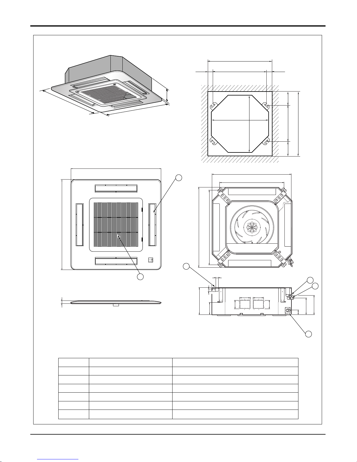
20 Universal System Air Conditioner
Ceiling Cassette 4-way
ATNH-DL
288
950
950
290
210.5
180
52
140
40
110
30
90
90
110
840
785
840
678
840 Unit size
840 Unit size
672 (Hanging bolt)
101.5101.5
875 (Ceiling opening)
875 (Ceiling opening)
785(Hanging bolt)
45
45
Unit:mm
4
1
2
3
950
950
5
6
30
Number Name Descripition
1 Liquid pipe connection 36k:ø6.35, 48/60k: ø9.52 flare
2 Gas pipe connection 36k:ø15.88, 48/60k: ø19.05flare
3 Drain pipe connection
4 Power supply connection
5 Air discharge grille
6 Air suction grille
(unit : mm)
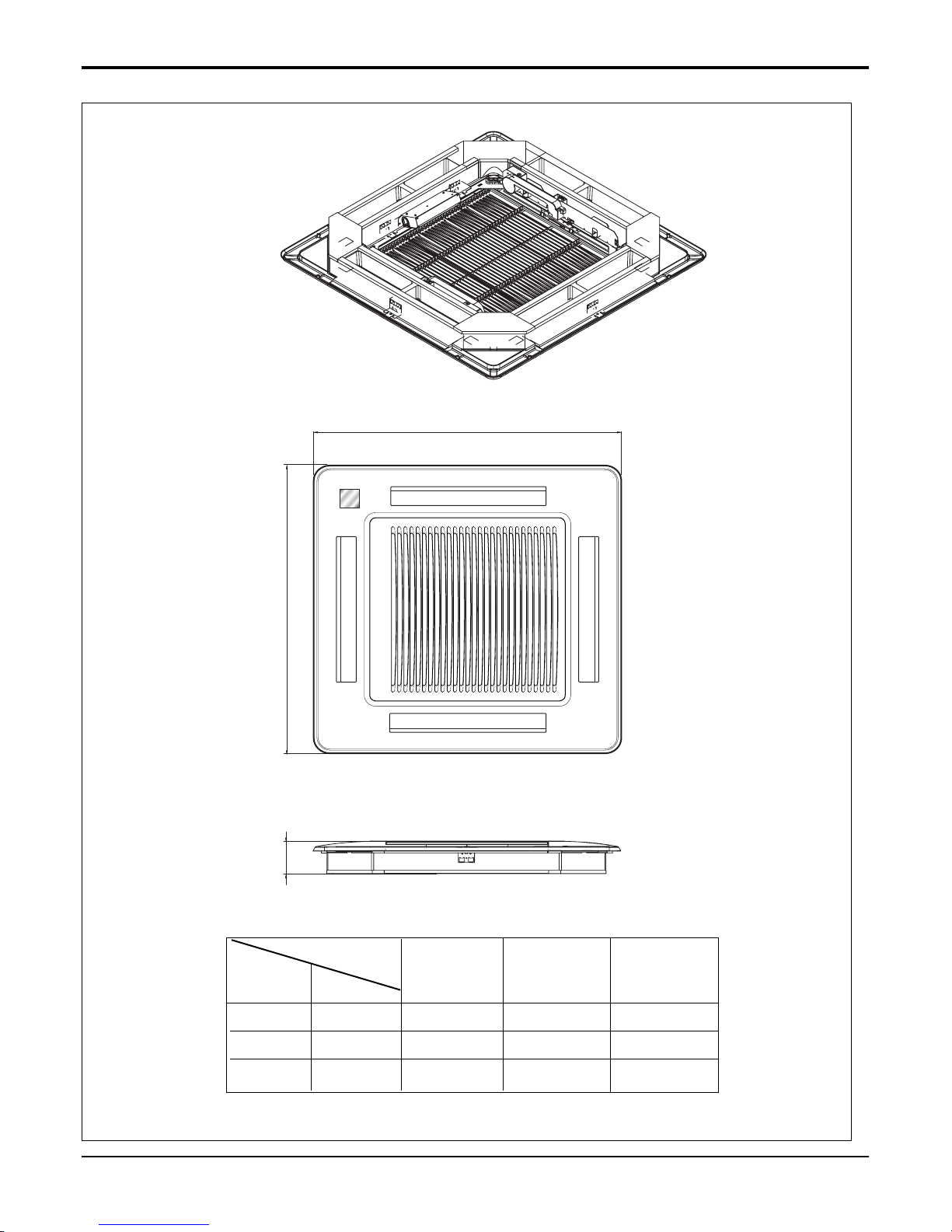
Service Manual 21
Ceiling Cassette 4-way
PT-HEF/HFF/HDF
W
D
H
W mm 670 850 950
Hmm909090
D mm 670 850 950
(unit : mm)
Model
PT-HEF PT-HFF PT-HDF
DIM
Unit
Ceiling Cassette 4-way
22 Universal System Air Conditioner
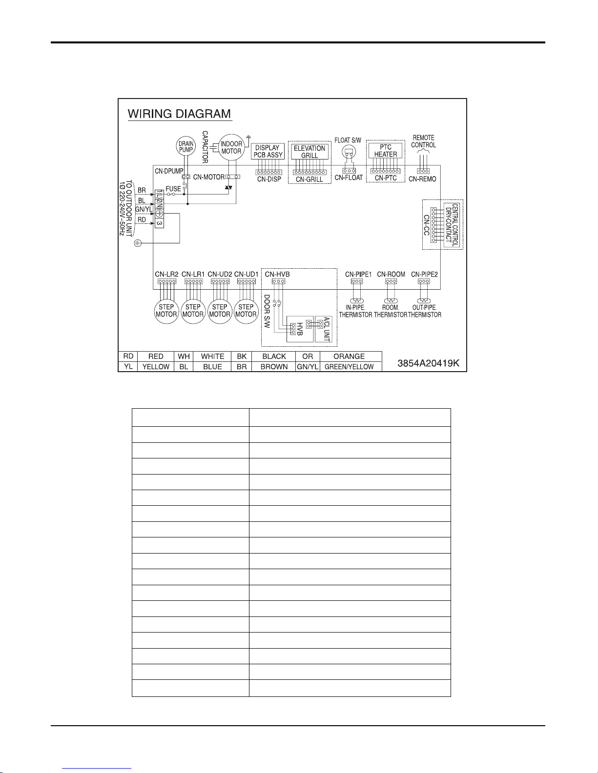
CONNECTOR NUMBER LOCATION
CN-POWER AC POWER SUPPLY
CN-MOTOR BLDC FAN MOTOR OUTPUT
CN-D/PUMP DRAIN PUMP OUTPUT
CN-DISP DISPLAY
CN-FLOAT FLOAT SWITCH INPUT
CN-PTC PTC HEATER INUT
CN-REMO REMOTE CONTROL
CN-GRILL GRILL CONTROL
CN-CC CENTRAL CONTROL
CN-PIPE2 DISCHARGE PIPE SENSOR
CN-ROOM ROOM SENSOR
CN-PIPE1 PIPE SENSOR
CN-HVB AIR CLEANER
CN-UD1 STEP MOTOR
CN-UD2 STEP MOTOR
CN-LR1 STEP MOTOR
CN-LR2 STEP MOTOR
5. Wiring Diagrams
5.1 Wiring Diagrams(Product)

Service Manual 23
Ceiling Cassette 4-way
5.2 Wiring Diagrams(Elevation Grill)
PT-HEF
PT-HFF/HDF
24 Universal System Air Conditioner
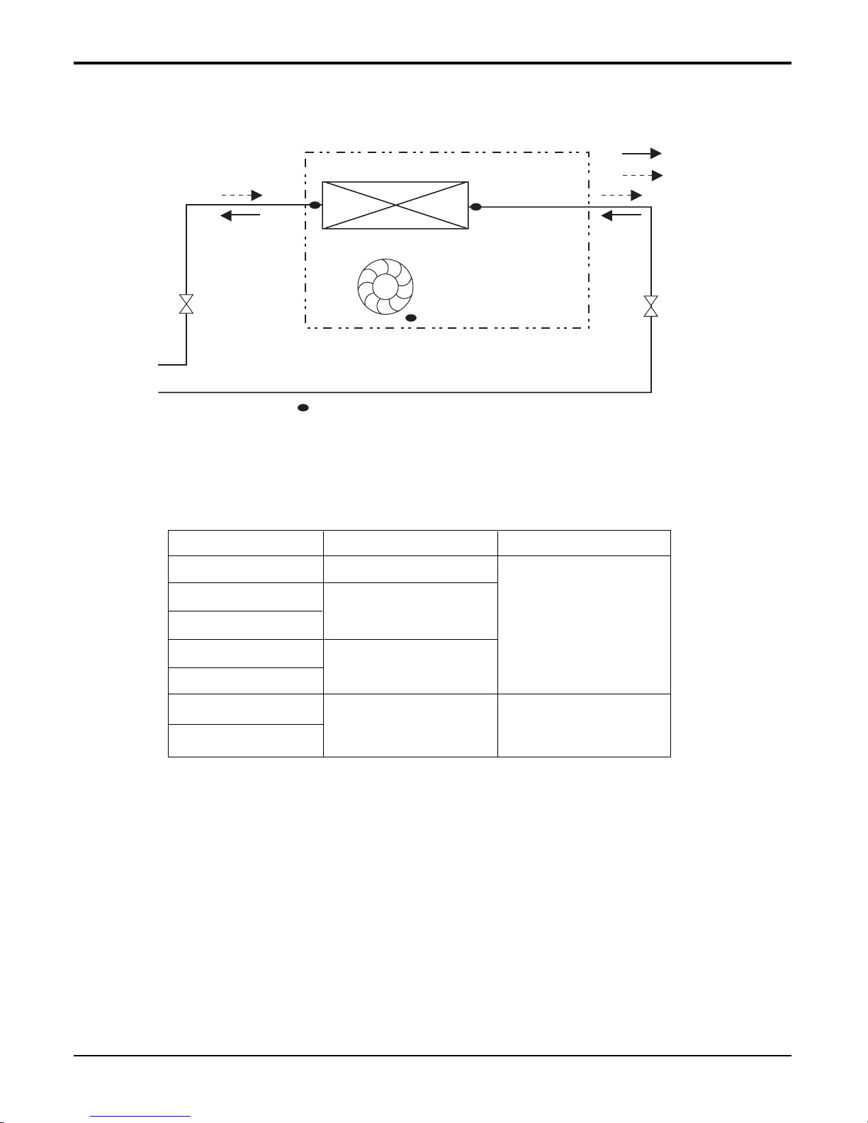
Ceiling Cassette 4-way
Refrigerant pipe connection port diameter
Model
ATNH126ELFC
ATNH186ELFC
ATNH246FLFC
ATNH306FLFC
ATNH366DLFC
ATNH486DLFC
ATNH606DLFC
Gas
9.52(3/8)
12.7(1/2)
15.88(5/8)
19.05(3/4)
Liquid
6.35(1/4)
9.52(3/8)
[unit: mm(inch)]
Heat Exchanger
Turbo Fan
lndoor unit
:Heating
:Cooling
: Thermistor
6. Piping Diagrams

Service Manual 25
Ceiling Cassette 4-way
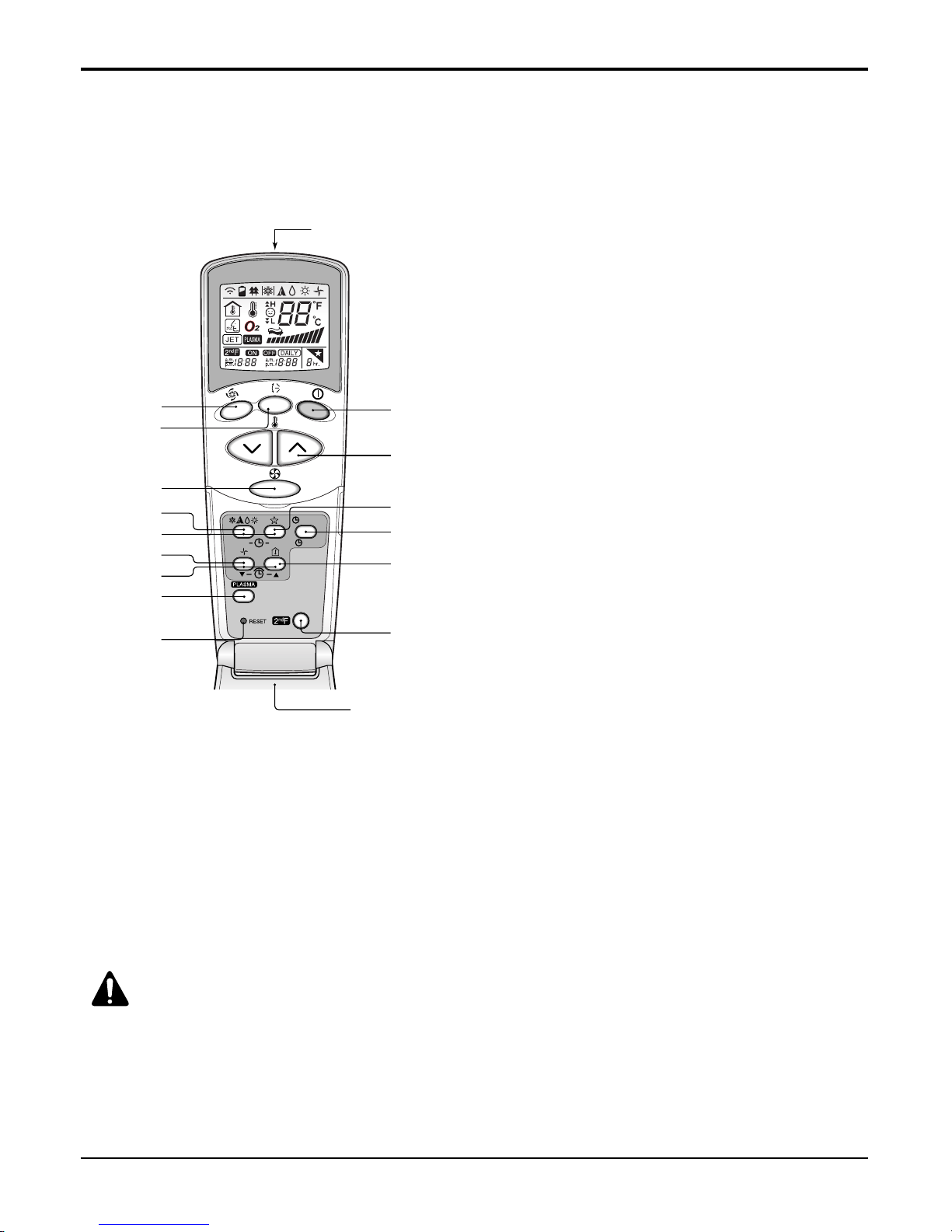
7. Operating Instructions
1. Operation display
Displays the operation conditions.
2. On/Off Button
Operation starts when this button is pressed, and
stops when the button is pressed again.
3. Set Temperature Button
Used to set the temperature when the desired temperature is obtained.
4. FAN Operation Button
Used to circulate room air without cooling or heating.
5. Fan Speed (Jet Cool Button: 4 way)
Used to set the desired fan speed or select Jet cool
mode.
6. Operation Mode Selection Button
Used to select the operation mode.
• Auto Operation Mode
• Cooling Operation Mode
• Soft Dry Operation Mode
• Heating Operation Mode(except cooling model)
7. Auto Swing Button
Used to swing up and down.
8.
Room Temperature Checking Button
Used to check the room temperature.
9. Plasma Air Clean Button (optional)
10. Timer Cancel Button
Used to cancel the timer.
11. Timer Set Button
Used to set the timer when the desired time is
obtained.
12.
Week Button
Used to set a day of the week.
13. Program Button
Used to set the weekly timer.
14. Holiday Button
Used to set a holiday of the week.
15. Time Set Button
Used to set the time of the day and change the time
in the weekly timer Function.
16. Set and Clear Button
Used to set and clear the weekly timer.
17. Swirl Button (4 way)
Used to select swirl mode.
Jet Cool Button (1 way)
18. Reset Button
Used to set the current time and clear the setting
time.
❈
Display temperature can be different from actual room temperature if the remote controller is installed
at the place where sun-rays are falling directly or the place nearby heat source.
Timer Cancel
Program Week
Hour Min
Holiday
Set/Clr
RESET
Plasma
ZONE
1234
Operation unit
Humidify
JET
AUTO
AUTO SWING OPERATION
FAN SPEED
Program set
SUB FUNCTION
SET TEMP
Room Temp
HI
MED
LO
Heater
Defrost
Filter
Preheat
Out door
Time
Timer
On
Set no. Time
Off
01 03 05 07 09 11 13 15 17 19 21 23
3
10
12
14
15
11
13
18
16
2
1
Heat Pump Model
Cooling Model
5
4
6
8
9
7
17
■ Name and Function of Remote Controller
26 Universal System Air Conditioner
Ceiling Cassette 4-way
This air-conditioner is equipped with wired remote controller basically. But if you want to be available with wireless remote
controller, you pay for it.
1. START/STOP BUTTON
Operation starts when this button is pressed and
stops when the button is pressed again.
2. OPERATION MODE SELECTION BUTTON
Used to select the operation mode.
3. ROOM TEMPERATURE
SETTING BUTTONS
Used to select the room temperature.
4. INDOOR FAN SPEED SELECTOR
Used to select fan speed in four steps
low, medium, high and CHAOS.
5. JET COOL
Used to start or stop the speed cooling/heating.
(Speed cooling/heating operates super high fan
speed.)
6. CHAOS SWING BUTTON
Used to stop or start louver movement and set the
desired up/down airflow direction.
7. ON/OFF TIMER BUTTONS
Used to set the time of starting and stopping operation.
8. TIME SETTING BUTTONS
Used to adjust the time.
9. TIMER SET/CANCEL BUTTON
Used to set the timer when the desired time is
obtained and to cancel the Timer operation.
10. SLEEP MODE AUTO BUTTON
Used to set Sleep Mode Auto operation.
11. AIR CIRCULATION BUTTON
Used to circulate the room air without cooling or
heating.
12. ROOM TEMPERATURE CHECKING BUTTON
Used to check the room temperature.
13. PLASMA(OPTIONAL)
Used to start or stop the plasma-purification function.
14. RESET BUTTON
Initialize remote controller.
15. 2nd F Button
Used prior to using modes printed in blue at the
bottom of buttons.
CAUTION:
of handling the Remote Controller
• Aim at the signal receiver on the wired remote controller so as to operate.
• The remote control signal can be received at a distance of up to about 7m.
• Be sure that there are no obstructions between the remote controller and the signal receptor.
• Do not drop or throw the remote controller.
• Do not place the remote controller in a location exposed to direct sunlight, or near the heating unit, or any other
heat source.
• Block a strong light over the signal receptor with a curtain or etc. so as to prevent the abnormal operation. (ex:electronic quick start, ELBA, inverter type fluorescent lamp)
❈ The wireless remote controller do not operate the swirl mode.
AUTO CLEAN
ON
OFF
CANCEL
SET
Flip-up door
(opened)
Signal transmitter
5
1
3
10
9
12
15
6
4
2
7
11
8
13
14
■ Wireless Remote Controller (optional)
Service Manual 27
Ceiling Cassette 4-way
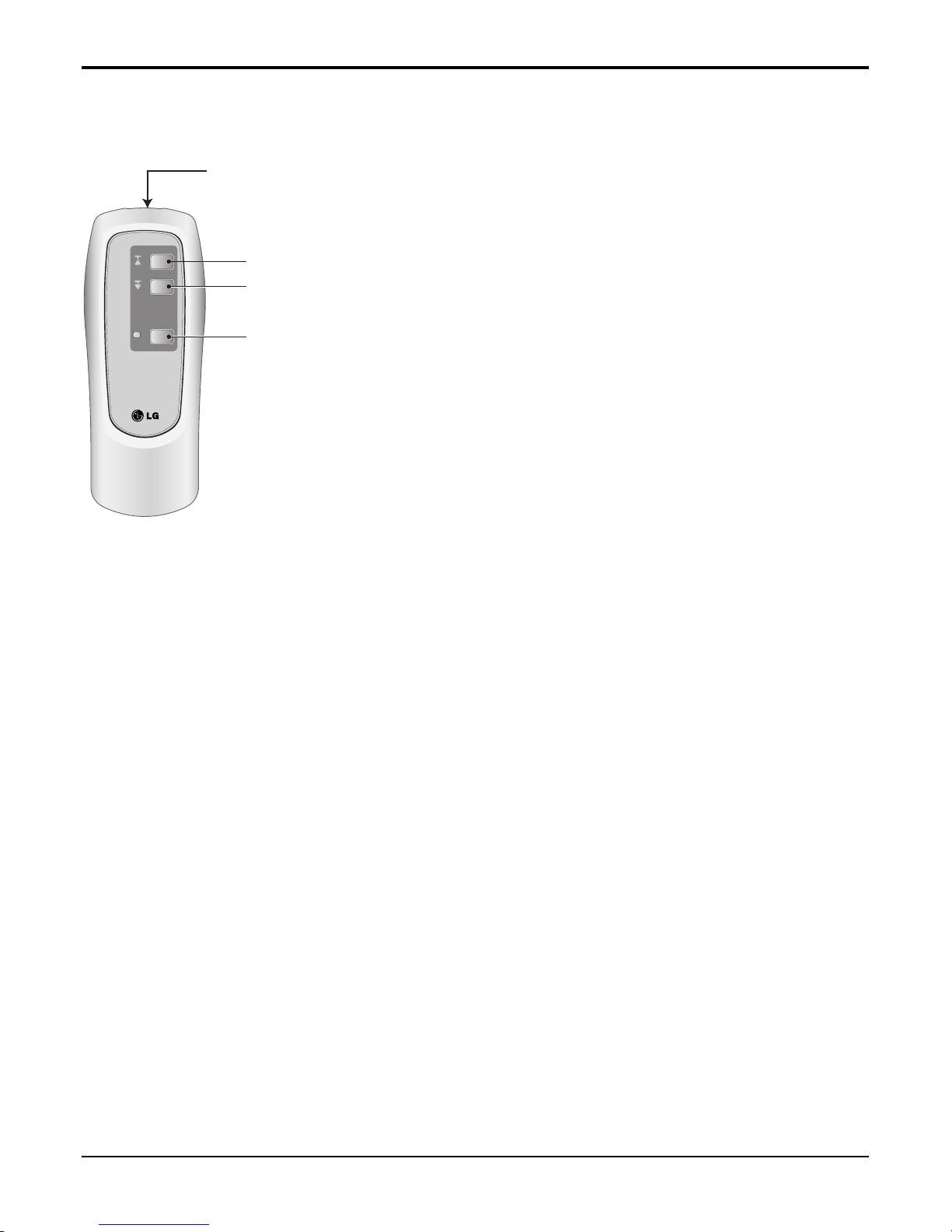
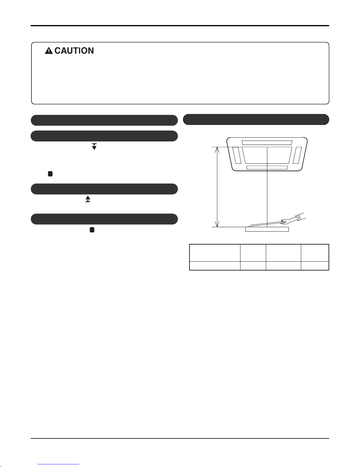
■ ELEVATION GRILL (REMOTE CONTROLLER_Accessory)
• How to Use Remote Controller
• Main Components of Lift Grill
As for operation of Remote Controller, use it by directing the transmitter part of Remote Controller to the receiver part of front panel
directly under front panel.
• Do not drop it down or into water. Or else there is worry about
trouble failure.
• Do not press hard the Remote Controller button with nail (ballpoint pen or other sharp substance). Or else there is worry
about trouble failure.
• In case when obstacle such as curtain hides the signal reception
part of receiver in between the space interval, Remote Controller
operation is infeasible.
➀ Lift grill front panel assembly
➁ Bolts for installation (4 EA, P/No. 3A00255K)
➂ Instruction manual
➃ Remote Controller for lift grill
Ascend
Signal transmitter
Descend
Stop
Ceiling Concealed Duct
28 Universal System Air Conditioner
Automatic stop distance
✳
If you want to change automatic distance setting,
consult with your sale agency.
Automatic Stop Distance of Grill
Ceiling height Low
Medium
High
(
Height: 3~4 m)
Automatic stop distance
1.5±0.5 m 2.5±0.5 m 3.5±0.5 m
- Depress the down button( ).
Then suction grill descends and stops automatically at a certain
distance.
- You may stop it at wanted distance point by depressing the stop button ( ) when descending.
- Depress the up button( ).
Then suction grill goes up and enters into the front panel.
1. Stop the Air Conditioner Operation
2. Descend the Suction Grill
3. Raise the Suction Grill
- Depress the stop button( ).
Make use of this when you want to stop it at your wished position.
4. Stop the Suction Grill during Rising
• Always stop the air conditioner operation for safety before operating lift grill.
• Take heed _ there is worry about dust fall etc. when suction grill descends.
• In case when the set automatic stop distance goes wrong, check the set value of operation panel and con-
firm if there is neither obstacle nor mankind.
• When you are not to remove obstacle, stop the operation before touching the obstacle.
• How to Operate the Lift Grill
Service Manual 29
Ceiling Cassette 4-way
8. Installation
• Please read this instruction sheet completely before installing the product.
• When the power cord is damaged, replacement work shall be performed by authorized personnel only.
• Installation work must be performed in accordance with the national wiring standards by authorized personnel only.
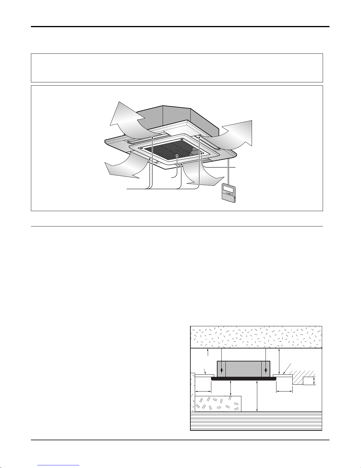
Anti-bacteria filter
Air
Intake
Air Outlet
Required Parts Required Tools
• Connecting cable
• Pipes: Gas side
Liquid side
• Hanging Bolt
(W 3/8 or M10 length 650mm)
• Insulated drain hose
• Additional Drain hose
(Inner Diameter ...........................32mm)
• Level
• Screw driver
• Electric drill
• Hole core drill (ø70mm)
• Flaring Tools set
• Torque Wrenches
• Hexagonal Wrench (4mm, 5mm)
• Gas-leak detector
• Owner’s Manual
• Thermometer
8.1 Selection of the best location
• There should not be any heat source or steam near the
unit.
• There should not be any obstacles to the air circulation.
• There should be provision of easy condensate drain.
• Taking into accounting the noise prevention criteria,
spot the installation location.
• Do not install the unit near the door way.
• Keep proper distances, of the unit, from ceiling, fence,
floor, walls and other obstacles as shown in figure.
• The indoor unit must have the maintenance space.
Unit:cm
Ceiling
Ceiling Board
Ceiling Board
30 or more
Above 250
400 or less
100
or more
50 or
more
50 or
more
30 or less
Floor
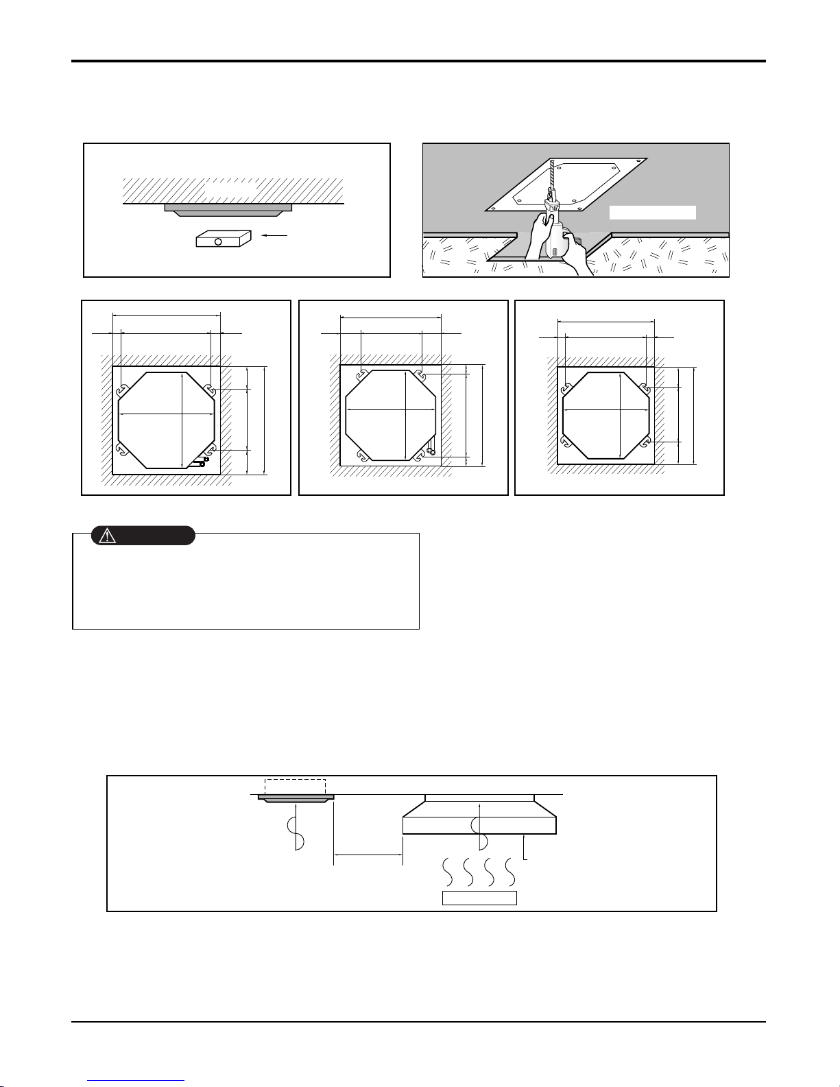
8.2 Ceiling opening dimensions and hanging bolt location
NOTE:
• Avoid the following installation location.
1. Such places as restaurants and kitchen where considerable amount of oil steam and flour is generated.
These may cause heat exchange efficiency reduction, or water drops, drain pump mal-function.
In these cases, take the following actions;
• Make sure that ventilation fan is enough to cover all noxious gases from this place.
• Ensure enough distance from the cooking room to install the air conditioner in such a place where it may not suck oily steam.
Ceiling board
Level gauge
Ceiling
Unit:mm
570 Unit size
570 Unit size
672 (Hanging bolt)
7575
600 (Ceiling opening)
600 (Ceiling opening)
521(Hanging bolt)
39.5
39.5
TE Model TF Model TD Model
Unit:mm
744 Unit size
744 Unit size
658 (Hanging bolt)
6666
790 (Ceiling opening)
790 (Ceiling opening)
572(Hanging bolt)
109
109
Unit:mm
840 Unit size
840 Unit size
672 (Hanging bolt)
101.5101.5
875 (Ceiling opening)
875 (Ceiling opening)
785(Hanging bolt)
45
45
• The dimensions of the paper pattern for installation are the same as those of the ceiling opening dimensions.
• Select and mark the position for fixing bolts and
piping hole.
• Decide the position for fixing bolts slightly tilted to
the drain direction after considering the direction
of drain hose.
• Drill the hole for anchor bolt on the wall.
• This air-conditioner uses a drain pump.
• Install the unit horizontally using a level gauge.
• During the installation, care should be taken not to
damage electric wires.
CAUTION
2. Avoid installng air conditioner in such places where cooking oil or iron powder is generated.
3. Avoid places where inflammable gas is generated.
4. Avoid place where noxious gas is generated.
5. Avoid places near high frequency generators.
Use the ventilation fan
for smoke-collecting
hood with sufficient
capacity.
Cooking table
Air conditioner
Take enough
distance
30 Universal System Air Conditioner
Ceiling Cassette 4-way
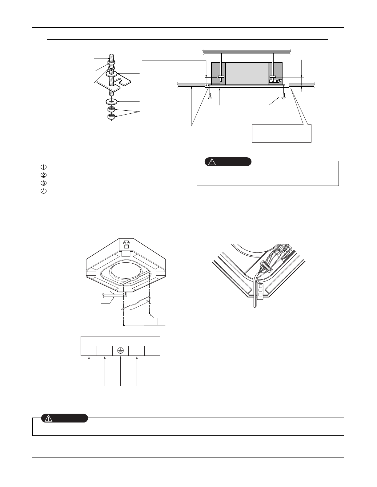
Service Manual 31
Ceiling Cassette 4-way
Set screw of
paper pattern (4 pieces)
Paper pattern
for installation
Ceiling board
150mm
Adjust the same height
Ceiling board
Ceiling
Flat washer for M10
(accessory)
Keep the length of the bolt
from the bracket to 40mm
Open the ceiling board
along the outer edge of the
paper pattern.
Flat washer for M10
(accessory)
Hanging bolt
(W3/8 or M10)
Nut
(W3/8 or M10)
Nut
(W3/8 or M10)
Spring washer
(M10)
Air Conditioner body
• The following parts are local purchasing.
Hanging Bolt - W 3/8 or M10
Nut - W 3/8 or M10
Spring Washer - M10
Plate Washer - M10
• Tighten the nut and bolt to prevent unit from
falling off.
CAUTION
[Air inlet side view]
Control box cover
Indoor
power cord
Remote
controller
cord
Control box cover
fitting screw(2 units)
Terminal Block in Indoor
1(L) 2(N) 3 4
Connected to outdoor unit
8.3 Wiring Connection
• Open the control box cover and connect the remote control cord and Indoor power wires.
Make sure that the screws of the terminal are free from looseness.
WARNING
32 Universal System Air Conditioner
Ceiling Cassette 4-way
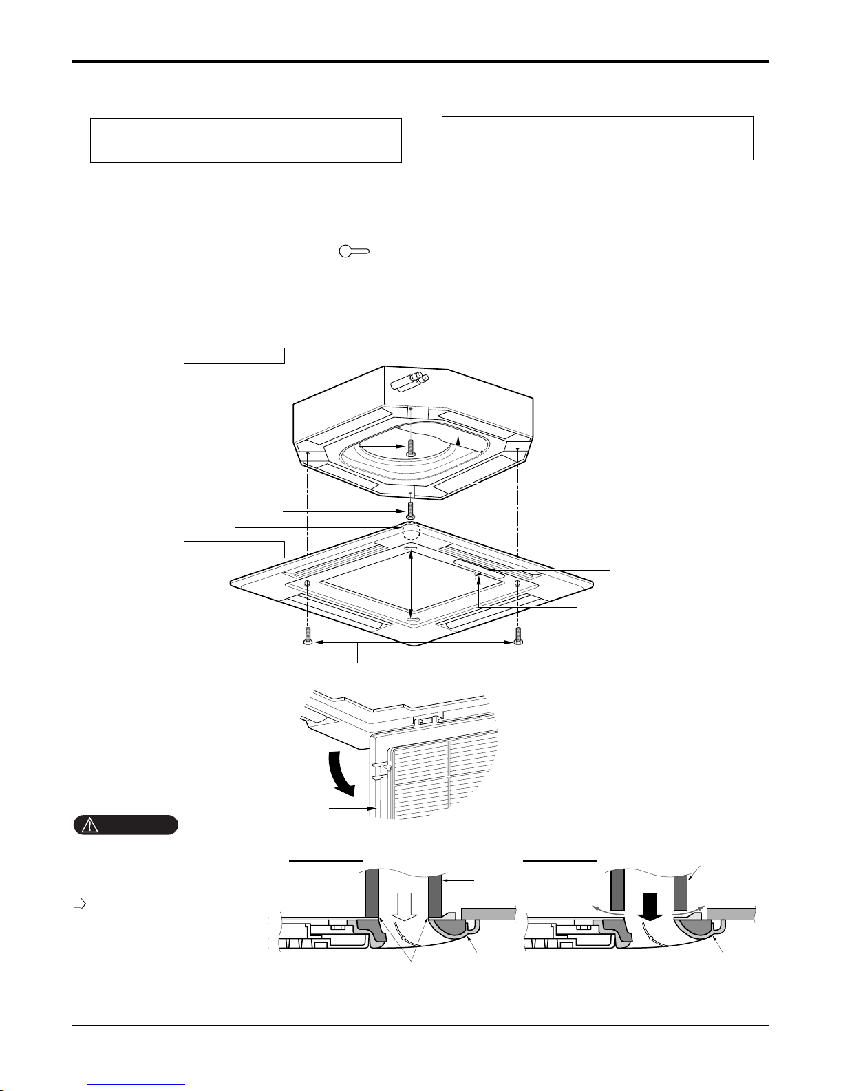
8.4 Installation of Decoration Panel
1. Temporarily fix two decoration panel fixing screws (hexagon M5 screw) on the unit body. (Tighten by
amount 10mm in length.)
The fixing screws (hexagon M5 screw) are included the indoor unit box.
2. Remove the air inlet grille from the decoration panel. (Remove the hook for the air inlet grille cord.)
3. Hook the decoration panel key hole ( ) on the screws fixed in step above, and slide the panel so
that the screws reach the key hole edge.
4. Retighten completely two temporarily fixed screws and other two screws. (Total 4 screws)
5. Connect the louver motor connector and display connector.
6. After tightening these screws, install the air inlet grille (including the air filter).
Decoration panel fixing screws
(hexagon M5 screws)
Temporally fitting at 2 places
(Tightening about 10mm)
Control box cover
Piping side
Inlet GrilleInlet Grille
Inlet Grille
Louver motor
Decoration panel fixing screws
(Hexagon M5 screw)
Air conditioner unit
Decoration panel
Key holes
Display
Lead wire for
louver motor and
display
The decoration panel has its installation
direction.
Before installing the decoration panel,
always remove the paper template.
CAUTION
Install certainly the decoration
panel.
Cool air leakage causes sweating.
Water drops fall.
Air conditioner
unit
Ceiling
board
Decoration panel
Decoration
panel
Fit the insulator (this part) and
be careful for cool air leakage
Good example
Air
Cool air leakage
(no good)
Bad example
Ceiling
board
Air conditioner unit
Service Manual 33
Ceiling Cassette 4-way
Decoration panel fixing screws
(hexagon M5 screws)
Temporally fitting at 2 places
(Tightening about 10mm)
Control box cover
Piping side
Inlet Grille
Louver motor
Decoration panel fixing screws
(Hexagon M5 screw)
Air conditioner unit
Decoration panel
Key holes
Inlet grille
Display
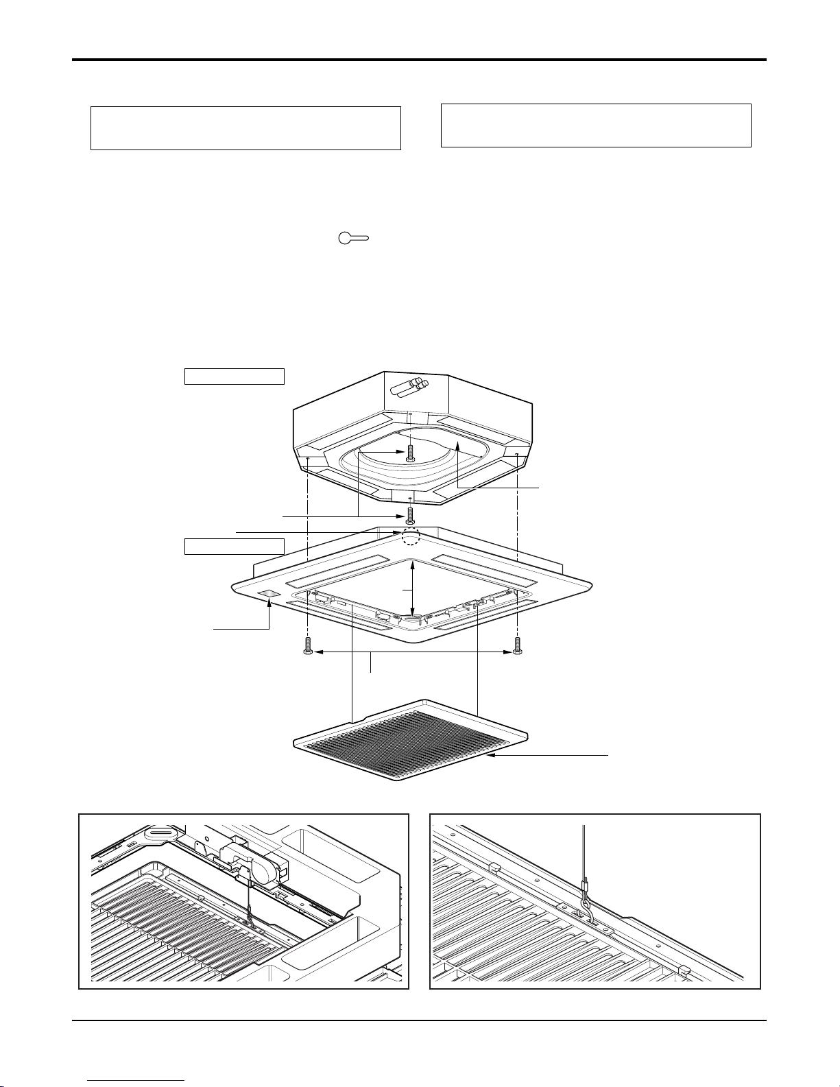
8.5 Installation of Decoration Panel(Elevation Grille)
1. Temporarily fix two decoration panel fixing screws (hexagon M5 screw) on the unit body. (Tighten by
amount 10mm in length.)
The fixing screws (hexagon M5 screw) are included unit box.
2. Remove the air inlet grille from the decoration panel. (Remove the hook for the air inlet grille cord.)
3. Hook the decoration panel key hole ( ) on the screws fixed in step above, and slide the panel so
that the screws reach the key hole edge.
4. Retighten completely two temporarily fixed screws and other two screws. (Total 4 screws)
5. Connect the louver motor connector display connector, elevation grille connector and power supply connector
6. After tightening these screws, install the air inlet grille (including the air filter).
The decoration panel has its installation
direction.
Before installing the decoration panel,
always remove the paper template.
Ceiling Concealed Duct
34 Universal System Air Conditioner
• Don't lay any material upon suction grill.
• Suction grill comprises 2 strands of wire. If any substance is placed on it then balance may be destroyed so that
the substance would drop down and cause a breakage or damage. Also the matter may cause trouble owing to
which the grill would not be correctly inserted at front panel.
• Don't shake suction grill. Or else there is worry that it may collide with adjacent material and the suction grill fall
down.
• Don't pull suction grill. Don't draw out suction grill irrationally. Or else there is worry that lift grill drive part is
damaged and suction grill might drop down.
• Don't place obstacle in lift passage of lift grill.
When suction grill descends, it automatically stops at a certain distance.
If there is any obstacle in lift passage, suction grill might drop down and there may be caused trouble failure of lift grill drive part.
• Turn off the air conditioner operation button before operating the lift grill.
Always stop the air conditioner operation for safety when suction grill descends.
• Don't damage lift rope by a sharp material. Or else there is worry about suction grill dropping because of rope
cutoff.
 Loading...