

LG AS-W306MMH0, AS-W306MMH1 Svc Manual

Room Air Conditioner
SVC MANUAL(Exploded View)
MODEL : AS-W306MMH0
AS-W306MMH1
CAUTION
Before Servicing the unit, read the safety precautions in General SVC manual.
Only for authorized service personnel.
Internal Use Only
http://biz.lgservice.com

- 2 -
Copyright ©2008 LG Electronics. Inc. All right reserved.
Only for training and service purposes
LGE Internal Use Only
Air Conditioner Service Manual
TABLE OF CONTENTS
LG Model Name.................................................................................................................................3
Safety Precautions ...........................................................................................................................5
Dimensions .....................................................................................................................................10
Product Specifications ..................................................................................................................12
Installation.......................................................................................................................................14
Flaring work and connection of piping.........................................................................................16
Connecting the cable between indoor unit and outdoor unit.....................................................23
Checking the drainage and forming the pipings .........................................................................25
Air purging ......................................................................................................................................27
Test running ....................................................................................................................................29
Functions.........................................................................................................................................30
Operation.........................................................................................................................................33
Disassembly....................................................................................................................................40
Schematic Diagram ........................................................................................................................44
Troubleshooting Guide ..................................................................................................................48
Exploded View ................................................................................................................................76
- 3 -
Copyright ©2008 LG Electronics. Inc. All right reserved.
Only for training and service purposes
LGE Internal Use Only
LG Model Name
LG Model Name
2003
12 - 345678910
Code Type Code of Model Meaning
1 Producing Center, A~Z L: Chang-won R22 N: India
Refrigerant A: Chang-won R410A Z: Brazil
C: Chang-won R407C D: Indonesia
T: China M: Mexico
K: Turkey R22 V: Vietnam
E: Turkey R410A S: Out Sourcing
H: Thailand
2 Product Type A~Z S: Split Type Air Conditioner
3 Cooling/Heating/Inverter A~Z C: Cooling only
H: Heat pump
X: C/O + E/Heater
Z: H/P + E/Heater
V: AC Inverter C/O
N: AC Inverter H/P
Q: DC Inverter C/O
W: DC Inverter H/P
4, 5 Capacity 0~9 Cooling/Heating Capacity
Ex. "09" → 9,000 Btu/h
6 Electric Range 1~9 1: 115V/60Hz, A: 220V, 50Hz, 3Phase
A~Z 2: 220V/60Hz B: 208~230V, 60Hz, 3Phase
3: 208-230V/60Hz C: 575V, 50Hz, 3Phase
5: 200-220V/50Hz D: 440~460, 60Hz, 3Phase
6: 220-240V/50Hz E: 265V, 60Hz
7: 110V, 50/60Hz F: 200V, 50/60Hz
8: 380-415V/50Hz
9: 380-415V/60Hz
7 Chassis A~Z Name of Chassis of Unit
Ex. LSP → SP Chassis
8 Look A~Z Look,
Color (Artcool Model)
9 Function A~Z
10 Serial No. 0~9 LG Model De
* ARTCOOL COLOR
velopment Serial No.
Basic A
Basic+4Way B
Plasma Filter C
Plasma Filter+4 Way D
Tele+LCD E
Tele+LCD+Nano plasma+4Way F
Nano Plasma F+(A/changeove)+A/clean+Low A G
Nano Plasma F+(A/changeove)+A/clean+4way+Low A H
Tele+LED+4way I
Internet J
Plasma F+4Way+Oxy generator K
Nano Plasma F+(A/changeove)+A/clean L
Nano Plasma F+(A/changeove)+A/clean+4way M
Nano Plasma F+(A/changeove)+A/clean+PTC N
Nano Plasma F+(A/changeove)+Autoclean+4way+PTC P
Nano Plasma F+(A/changeove)+A/clean+4way+Low A+PTC Q
Negative ION+A/Clean R
(Nano)Plasma+Negative ION+A/Clean S
4way+(Nano)Plasma F+Negative ION+Healthy dehumidification+A/Clean
T
Nano Plasma F+4Way+(A/changeove)+A/clean+ U
R Mirror
W White
B Blue
D Wood
M Metal
C Cherry
- 4 -
Copyright ©2008 LG Electronics. Inc. All right reserved.
Only for training and service purposes
LGE Internal Use Only
LG Model Name
2004~
12 - 345678910
Code Type Code of Model Meaning
1 Producing Center, A~Z
L Chang_won R22
A Chang_won R410A
C Chang_won R407C
T China
K Turkey R22
E Turkey R410A
H Thailand
N India
Z Brazil
D Indonesia
X Mexico
V Vietnam
S Out sourcing
Refrigerant
2 Product Type A~Z S: Split Type Air Conditioner
3 Cooling/Heating/Inverter A~Z C: Cooling only
H: Heat pump
X: C/O + E/Heater
Z: H/P + E/Heater
V: AC Inverter C/O
N: AC Inverter H/P
Q: DC Inverter C/O
W: DC Inverter H/P
4, 5 Capacity 0~9 Cooling/Heating Capacity
Ex. "09" → 9,000 Btu/h
6 Electric Range 1~9 1: 115V/60Hz, A: 220V, 50Hz, 3Phase
A~Z 2: 220V/60Hz B: 208~230V, 60Hz, 3Phase
3: 208-230V/60Hz C: 575V, 50Hz, 3Phase
5: 200-220V/50Hz D: 440~460, 60Hz, 3Phase
6: 220-240V/50Hz E: 265V, 60Hz
7: 110V, 50/60Hz F: 200V
CHASSIS Look
D
K
L
G
M
N
D
P
Division
Panel Type(Deluxe)
Fighting 'Look'
(LG1)
(LG2)-SEMI PANEL
OEM1
OEM2
Panel Type(Deluxe)
LG3
, 50/60Hz
8: 380-415V/50Hz
9: 380-415V/60Hz
7 Chassis A~Z Name of Chassis of Unit
Ex. LSP → SP Chassis
8 Look A~Z Look,
Color (Artcool Model)
9 Function A~Z
10 Serial No. 0~9 LG Model De
* ARTCOOL COLOR
velopment Serial No.
R Mirror
W White
B Blue
D Wood
M Metal
C Cherry
S4/S5
S6
SQ
SR
ST
Basic A
Basic+4Way B
Plasma Filter C
Plasma Filter+4 Way D
Tele+LCD E
Tele+LCD+Nano plasma+4Way F
NBF F+(A/changeove)+A/clean+Low A G
NBF F+(A/changeove)+A/clean+4way+Low A H
Tele+LED+4way I
Internet J
Plasma F+4Way+Oxy generator K
NBF F+(A/changeove)+A/clean L
NBF F+(A/changeove)+A/clean+4way M
NBF F+(A/changeove)+A/clean+PTC N
NBF F+(A/changeove)+Autoclean+4way+PTC P
NBF F+(A/changeove)+A/clean+4way+Low A+PTC Q
(Nano)Plasma+ION+A/Clean S
4way+(Nano)Plasma F+
Negative ION+Healthy dehumidification
+A/Clean T
Nano Plasma F+4Way+(A/changeove)+A/clean+Oxy generator U
4way+(Nano)Plasma F+Negative ION+Healthy dehumidification+A/Clean+Oxy generator
V
Dry contact W
Wire remocon 8
- 5 -
Copyright ©2008 LG Electronics. Inc. All right reserved.
Only for training and service purposes
LGE Internal Use Only
Safety Precautions
Safety Precautions
To prevent injury to the user or other people and property damage, the following instructions must
be followed.
■ Incorrect operation due to ignoring instruction will cause harm or damage. The seriousness is
classified by the following indications.
■ Meanings of symbols used in this manual are as shown below.
This symbol indicates the possibility of death or serious injury.
This symbol indicates the possibility of injury or damage to properties only.
Be sure not to do.
Be sure to follow the instruction.
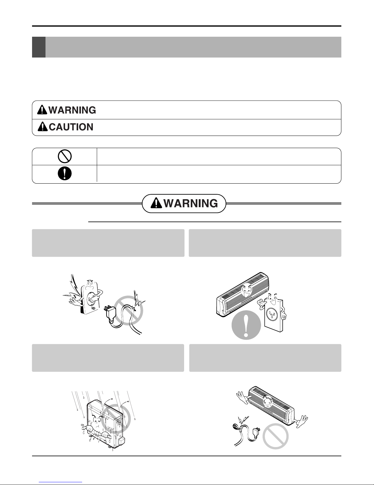
Do not use damaged power cords, plugs, or a
loose socket.
Always use the power plug and socket with the
ground terminal.
• There is risk of fire of electric shock. • There is risk of electric shock.
Install the panel and the cover of control box
securely.
Do not modify or extend the power cord.
• There is risk of fire of electric shock. • No grounding may cause electric shock.
■ Installation
- 6 -
Copyright ©2008 LG Electronics. Inc. All right reserved.
Only for training and service purposes
LGE Internal Use Only
Safety Precautions
Do not install the product on a defective installation stand.
Be sure the installation area does not
deteriorate with age.
• It may cause injury, accident, or damage to the
product.
• If the base collapses, the air conditioner could fall
with it, causing property damage, product failure,
and personal injury.
• Sharp edges could cause injury. Be especially careful of the case edges and the fins on the condenser
and evaporator.
•
There is risk of fire, electric shock, explosion, or injury.
Be cautious when unpacking and installing the
product.
For installation, always contact the dealer or
an Authorized service center
For re-installation of the installed product,
always contact a dealer or an authorized service center.
Do not install, remove, or re-install the unit by
yourself.
• There is risk of fire, electric shock, explosion, or
injury.
• There is risk of fire, electric shock, explosion, or
injury.
- 7 -
Copyright ©2008 LG Electronics. Inc. All right reserved.
Only for training and service purposes
LGE Internal Use Only
Safety Precautions
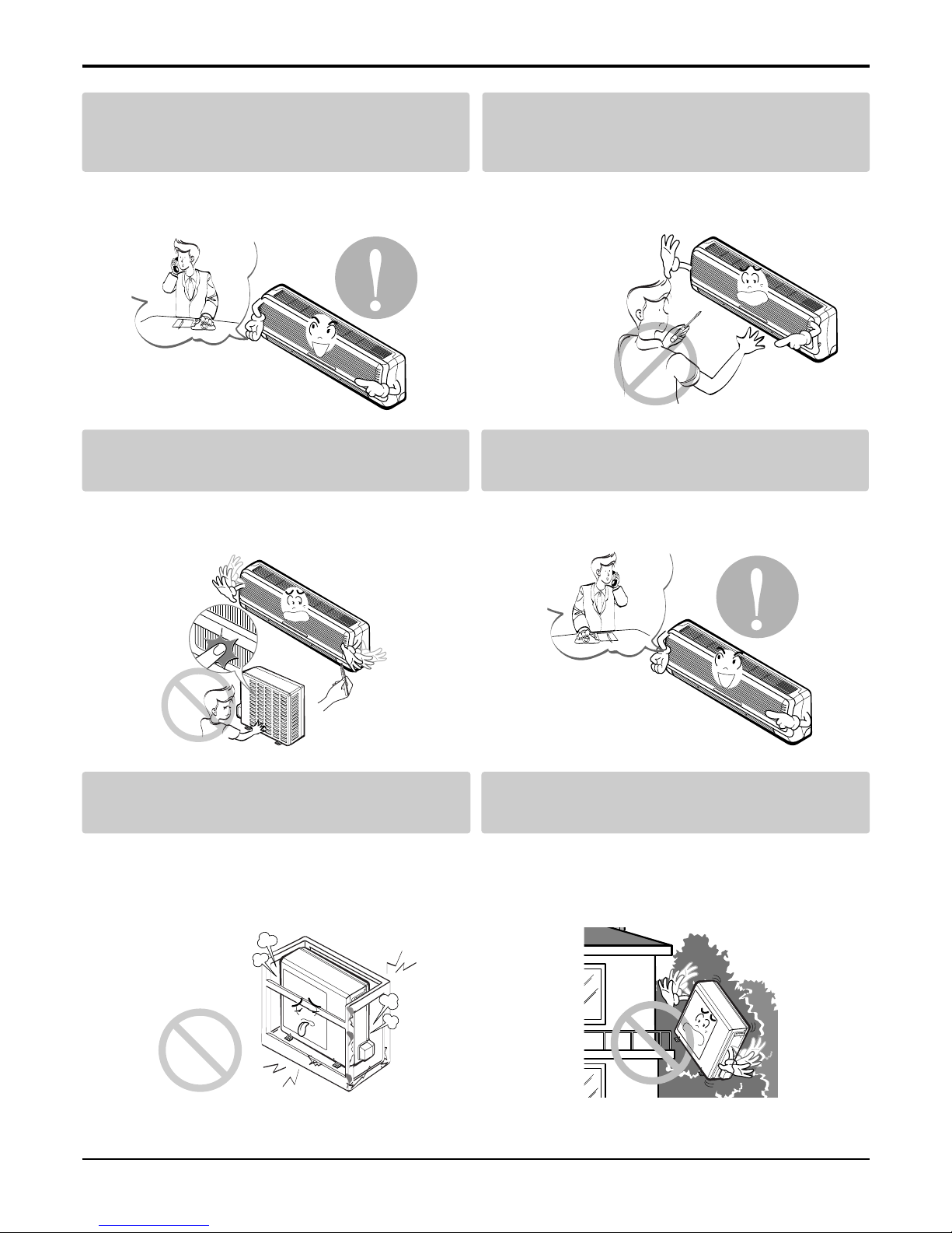
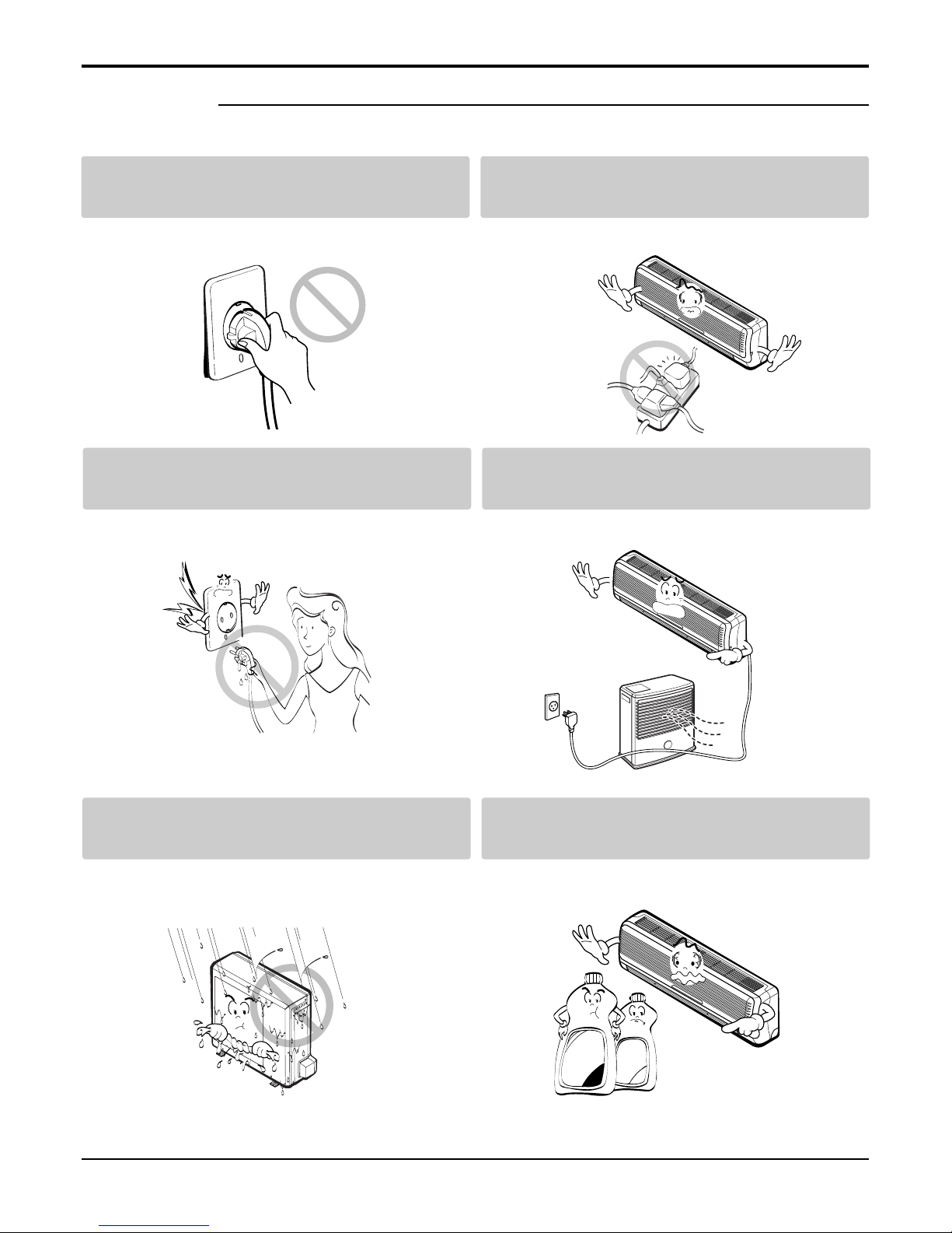
■ Operation
Do not turn the air-conditioner ON or OFF by
plugging or unplugging the power plug.
Use a dedicated outlet for this appliance.
• There is risk of fire or electrical shock. • There is risk of fire or electrical shock.
Grasp the plug to remove the cord from the
outlet. Do not touch it with wet hands.
Do not place a heater or other appliances near
the power cable.
• There is risk of fire or electrical shock. • There is risk of fire and electric shock.
Do not allow water to run into electrical parts. Do not store or use flammable gas or com-
bustibles near the air conditioner.
• There is risk of fire, failure of the product, or electric
shock.
• There is risk of fire or failure of product.
Wax
Thinner
- 8 -
Copyright ©2008 LG Electronics. Inc. All right reserved.
Only for training and service purposes
LGE Internal Use Only
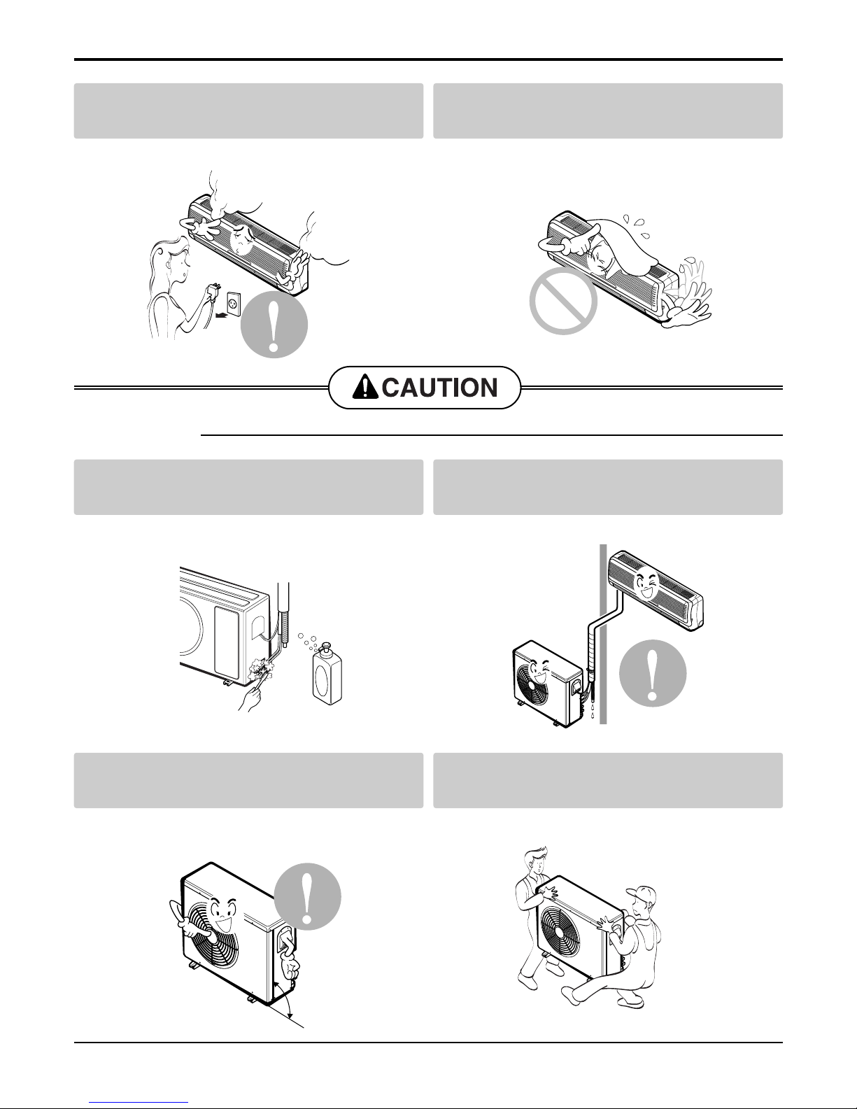
Always check for gas (refrigerant) leakage after
installation or repair of product.
Install the drain hose to ensure that water is
drained away properly.
• Low refrigerant levels may cause failure of product. • A bad connection may cause water leakage.
Keep level even when installing the product. Use two or more people to lift and transport
the air conditioner.
• To avoid vibration or water leakage. • Avoid personal injury.
■ Installation
90˚
Unplug the unit if strange sounds, odors, or
smoke comes from it.
Be cautious that water could not enter the
product.
• There is risk of electric shock or fire. • There is risk of fire, electric shock, or product damage.
Safety Precautions
- 9 -
Copyright ©2008 LG Electronics. Inc. All right reserved.
Only for training and service purposes
LGE Internal Use Only
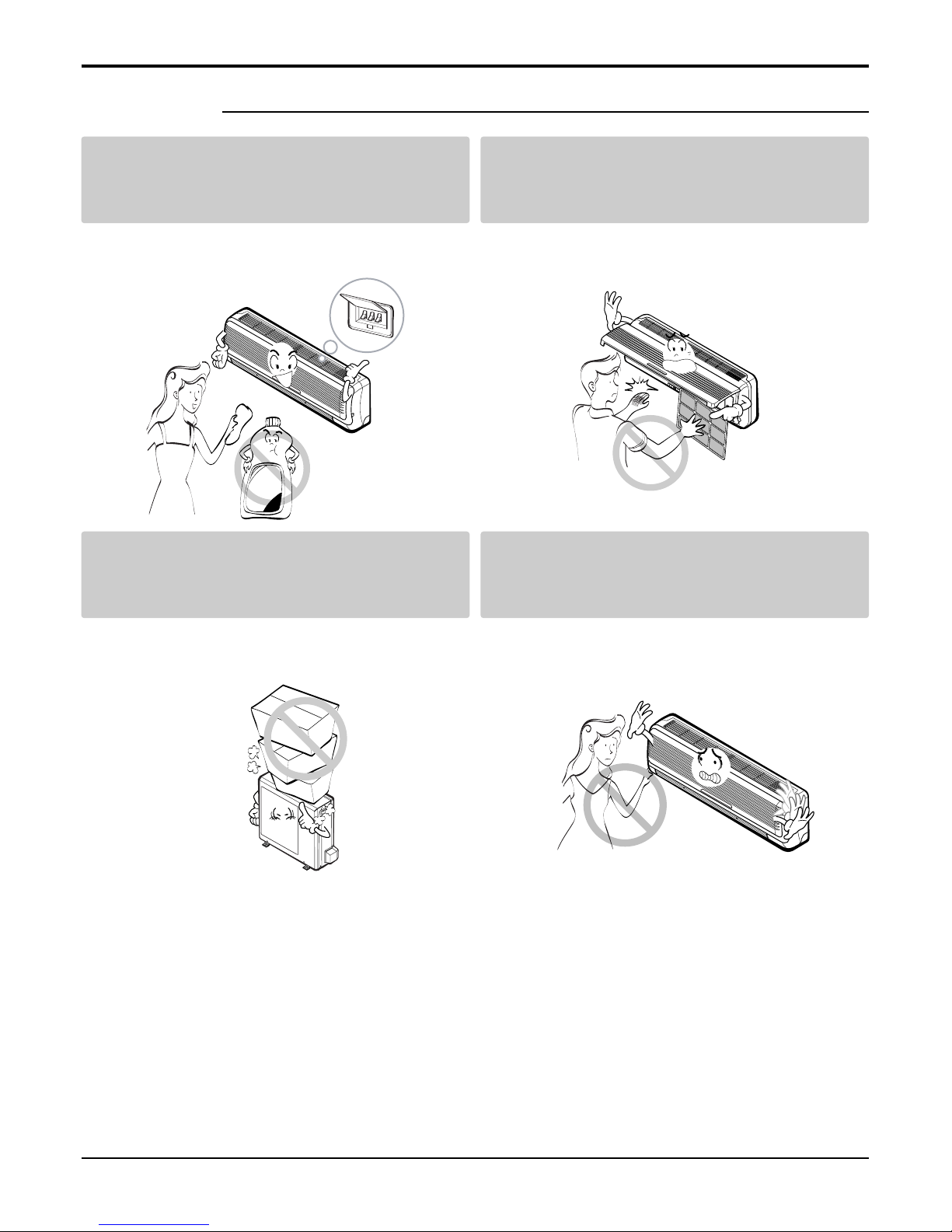
Use a soft cloth to clean. Do not use harsh
detergents, solvents, etc.
Do not touch the metal parts of the product
when removing the air filter. They are very
sharp!
• There is risk of fire, electric shock, or damage to the
plastic parts of the product.
• There is risk of personal injury.
Do not step on or put anyting on the product.
(outdoor units)
Do not insert hands or other objects through
the air inlet or outlet while the air conditioner
is plugged in.
• There is risk of personal injury and failure of product. • There are sharp and moving parts that could cause
personal injury.
■ Operation
Wax
Safety Precautions
- 10 -
Copyright ©2008 LG Electronics. Inc. All right reserved.
Only for training and service purposes
LGE Internal Use Only
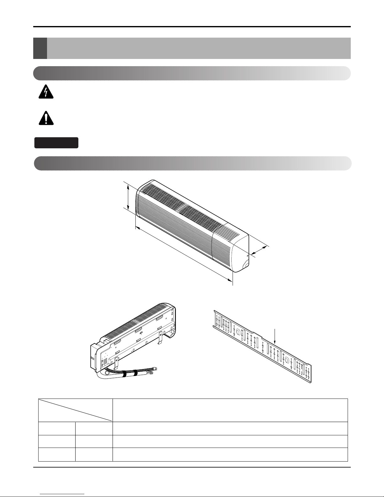
Dimensions
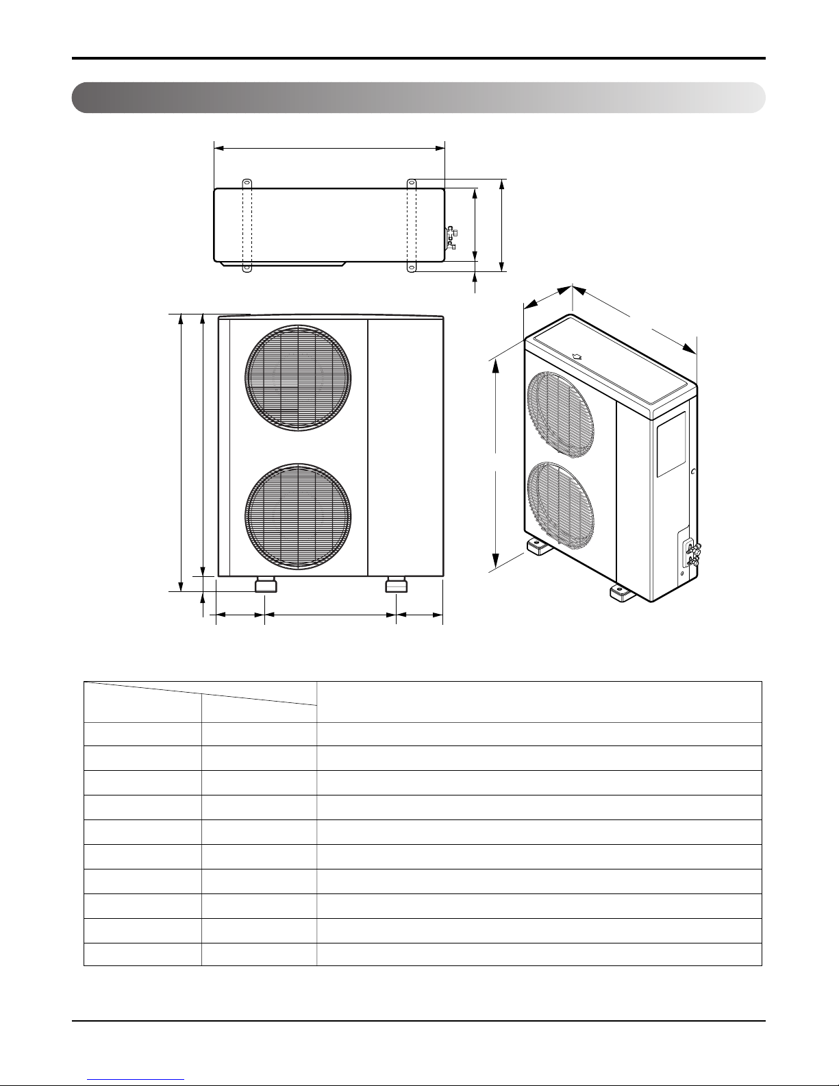
Dimensions
D
H
W
Installation Plate
W mm(inch) 1,259(49.6)
H mm(inch) 349(13.7)
D mm(inch) 205(8.1)
Model
Dimension
30k Btu Series
Indoor Unit
This symbol alerts you to the risk of electric shock.
This symbol alerts you to hazards that could cause harm to the
air conditioner.
This symbol indicates special notes.
NOTICE
Symbols Used in this Manual
- 11 -
Copyright ©2008 LG Electronics. Inc. All right reserved.
Only for training and service purposes
LGE Internal Use Only
Dimensions
L4
L3
H
L7L5L6
W
D
L1
L2
D
W
H
MODEL
DIM unit
W mm 870
H mm 1,060
D mm 320
L1 mm 360
L2 mm 20
L3 mm 1,040
L4 mm 20
L5 mm 550
L6 mm 160
L7 mm 165
Outdoor Unit
30k Btu Series
- 12 -
Copyright ©2008 LG Electronics. Inc. All right reserved.
Only for training and service purposes
LGE Internal Use Only
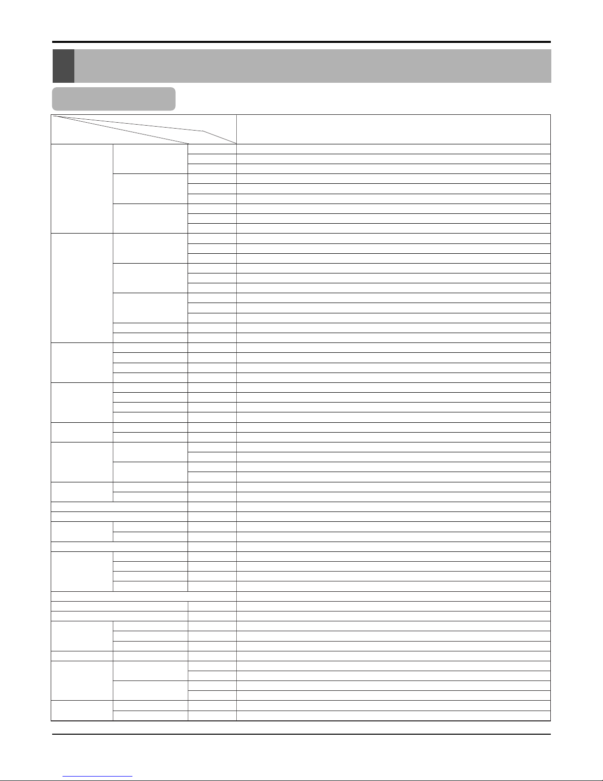
Product Specifications
Product Specifications
Table-1
Model Name
Item Unit
W
MIN kcal/h.(W)
Btu/h.
W
Cooling Capacity Type kcal/h.(W)
Btu/h.
W
Max kcal/h.(W)
Btu/h.
W
MIN kcal/h.(W)
Btu/h.
W
Heating Capacity Type kcal/h.(W)
Btu/h.
W
Max kcal/h.(W)
Btu/h.
IN:20°C,Out: -10°C(Heater ON)
Btu/h.
IN:20°C,Out: -10°C(Heater OFF)
Btu/h.
Power Input Cooling W
Heating W
Heating(-10°C,Heater ON)
W
Heating(-10°C,Heater OFF)
W
Running Current Cooling A
Heating A
Heating(-10°C,Heater ON)
A
Heating(-10°C,Heater OFF)
A
Starting Current Cooling A
Heating A
Cooling kcal/hW
EER Btu/h.W
Heating kcal/hW
Btu/h.W
COP Cooling W/W
Heating W/W
Power Supply Ø,V,Hz
Power Factor %
Air Circulation Indoor,Max m3/min(CFM)
Outdoor,Max m3/min(CFM)
Moisture Removal l/h.(pts/h.)
Noise Level Indoor,High dB(A)±3
(Sound Med. dB(A)±3
Pressure,1m) Low dB(A)±3
Outdoor,Max dB(A)±3
Refrigerant(R410A)Charge
Power Cord AWG#:P*mm
2
Connecting Cable AWG#:P*mm
2
Connecting Tube Liquid Side mm(in)
(Ø. Socket Flare) Gas Side mm(in)
Length,std m(in)
Drain Hose (O.D , I.D) mm(in)
Indoor mm
Dimension inch
(W*H*D) Outdoor mm
inch
Net Weight Indoor kg(lbs)
Outdoor kg(lbs)
3,016
2,594
10,294
8,000
6,879
27,297
9,350
8,041
31,910
2,670
2,296
9,113
9,500
8,169
32,415
10,223
8,792
34,890
-
2,800
3,710
-
-
12.5
16.3
-
-
12.5
16.3
2.46
9.75
2.20
8.73
2.86
2.56
1,220-240,50
97
21(742)
58(2,048)
3.156.62)
48
46
43
54
2,440
12:3*2.5
18:4*0.75
6.35(1/4)
15.88(5/8)
7.5(295)
32.5, 30(1.27, 1.18)
1,259*205*349
49.5*6.8*13.7
870*1,038*320
34.2*40.8*12.5
20(44.1)
80(176.4)
AS-W306MMH0
- 13 -
Copyright ©2008 LG Electronics. Inc. All right reserved.
Only for training and service purposes
LGE Internal Use Only
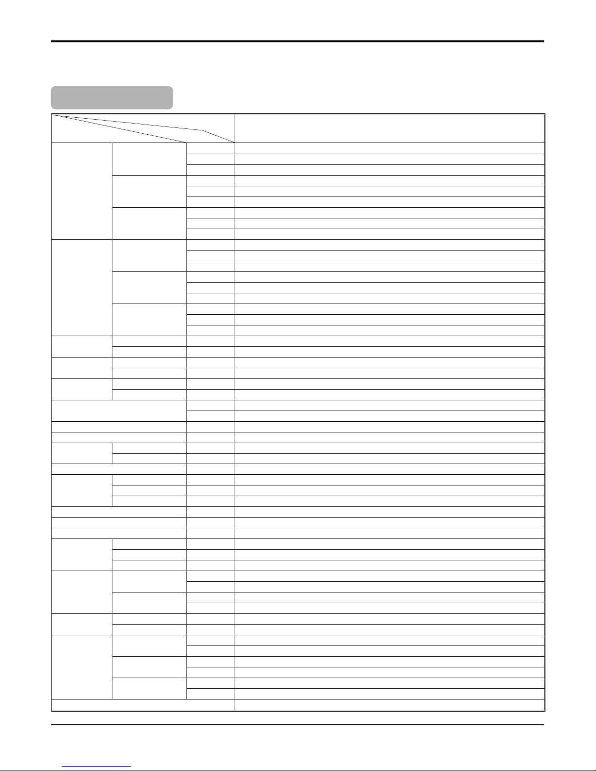
Product Specifications
Table-2
Buyer Models
Item Unit
Cooling Capacity Min W
kcal/h
Btu/h
Rating W
kcal/h
Btu/h
Max W
kcal/h
Btu/h
Heating Capacity Min W
kcal/h
Btu/h
Rating W
kcal/h
Btu/h
Max W
kcal/h
Btu/h
Power Input Cooling W
Heating W
Running Current Cooling A
Heating A
Starting Current Cooling A
Heating A
EER W/W
Btu/h.W
COP W/W
Power Supply Ø,V,Hz
Air Circulation Indoor,Max m3/min (l/s)
Outdoor,Max m3/min (l/s)
Moisture Removal l/h (pts/h)
Noise Level Indoor,High dB(A)±3
(Sound Low dB(A)±3
Pressure,1m) Outdoor,Max dB(A)±3
Refrigerant (R410A) Charge g (oz)
Power Cord P*mm
2
Connecting Cable P*mm
2
Connecting Tube Liquid Side mm (in)
(Ø. Socket Flare) Gas Side mm (in)
Length,std m (in)
Dimension Indoor mm
(W*H*D) in.
Outdoor mm
in.
Net Weight Indoor kg (lbs)
Outdoor kg (lbs)
Energy Labeling Capacity Cooling
Heating
Energy Consumption Cooling
Heating
Star Rating Cooling
Heating
Tool (IN/OUT)
3,016
2,594
10,294
7,510
6,457
25,624
9,350
8,041
31,910
2,670
2,296
9,113
9,500
8,168
32,414
10,223
8,792
34,890
2,840
4,140
12.5
17.6
12.5
17.6
2.64
9.02
2.29
1,220-240,50
21.0 (350)
58 (966)
3.1 (6.6)
48
43
54
2,100 (74.1)
3*2.5
4*0.75
6.35(1/4)
15.88((5/8)
7.5(295)
1259*205*349
49.5*6.8*13.7
1,038*870*320
34.2*40.8*12.5
20 (44.1)
80 (176.4)
7.51
9.50
2.84
4.14
2.5
1.0
SM+UE2
AS-W306MMH1
- 14 -
Copyright ©2008 LG Electronics. Inc. All right reserved.
Only for training and service purposes
LGE Internal Use Only
Installation
Installation
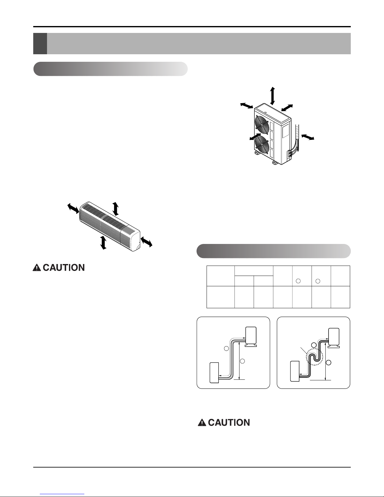
Selection of the Best Location
Piping Length and Elevation
Indoor unit
■ Do not have any heat or steam near the unit.
■ Select a place where there are no obstacles in
front of the unit.
■ Make sure that condensation drainage can be
conveniently routed away.
■ Do not install near a doorway.
■ Ensure that the space around the left and right of
the unit is more than 30cm. The unit should be
installed as high on the wall as possible, allowing
a minimum of 12cm from ceiling.
■ Use a stud finder to locate studs to prevent
unnecessary damage to the wall.
Outdoor unit
■ If an awning is built over the unit to prevent direct sun-
light or rain exposure, make sure that heat radiation
from the condenser is not restricted.
■ Ensure that the space around the back and sides is
more than 10cm. The front of the unit should have
more than 70cm of space.
■ Do not place animals and plants in the path of the
warm air.
■ Take the air conditioner weight into account and select
a place where noise and vibration are minimum.
■ Select a place so that the warm air and noise from the
air conditioner do not disturb neighbors.
■ Rooftop Installations:
If the outdoor unit is installed on a roof structure, be
sure to level the unit. Ensure the roof structure and
anchoring method are adequate for the unit location.
Consult local codes regarding rooftop mounting.
If the outdoor unit is installed on root structures or walls,
this may result in excessive noise and vibration, and
maybe also classed as non serviceable installation.
More than 12cm
More than
30cm
More than
30cm
More than 2.3m
More than 10cm More than 10cm
More
than 60cm
More than 60cm
More than 70cm
In case more than 5m
• Capacity is based on standard length and maximum
allowance length is on the basis of reliability.
• Oil trap should be installed every 5~7 meters.
Outdoor unit
Indoor unit
A
B
A
Oil trap
Outdoor unit
Indoor unit
B
Install the indoor unit on the wall where the height
from the floors more than 2.3 meters.
A minimum pipe run of 7.5 meters is required to minimise vibration & excessive noise.
30k 5/8" 1/4" 7.5 15 30 35
Pipe Size
Capacity
(Btu/h)
GAS LIQUID
Max.
length
A (m)
Additional
Refrigerant
(g/m)
Max.
Elevation
B (m)
Standard
Length
(m)
30k

- 15 -
Copyright ©2008 LG Electronics. Inc. All right reserved.
Only for training and service purposes
LGE Internal Use Only
Installation
How to Fix Installation Plate Drill a Hole in the Wall
The wall you select should be strong and solid enough to prevent
vibration
1. Mount the installation plate on the wall with four
type A screws. If mounting the unit on a concrete
wall, use anchor bolts.
Mount the installation plate horizontally by
aligning the centerline using a level.
2. Measure the wall and mark the centerline. It is also
important to use caution concerning the location
of the installation plate-routing of the wiring to
power outlets is through the walls typically.
Drilling the hole through the wall for piping connections must be done safely.
5-7mm
(0.2~0.3")
Indoor
WALL
Outdoor
Installation Plate
Type "A" screw
Right rear piping
30k
Left rear piping
50mm
ø
70mm180mm
115mm
■ Drill the piping hole with a ø70mm hole core drill.
Drill the piping hole at either the right or the left
with the hole slightly slanted to the outdoor side.
- 16 -
Copyright ©2008 LG Electronics. Inc. All right reserved.
Only for training and service purposes
LGE Internal Use Only
Flaring work and connection of piping
Flaring work and connection of piping
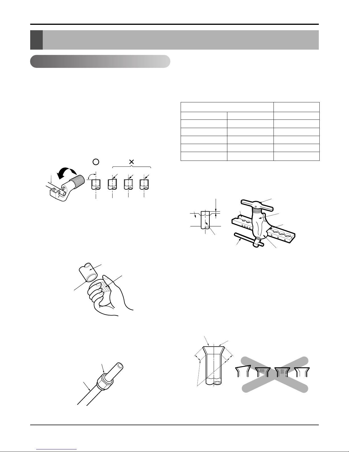
Flaring work
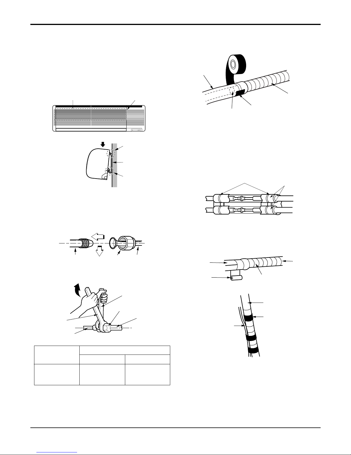
Main cause for gas leakage is due to defect in flaring work. Carry out correct flaring work in the following procedure.
Cut the pipes and the cable.
■ Use the piping kit accessory or the pipes
purchased locally.
■ Measure the distance between the indoor and the
outdoor unit.
■ Cut the pipes a little longer than measured
distance.
■ Cut the cable 1.5m longer than the pipe length.
Burrs removal
■ Completely remove all burrs from the cut cross
section of pipe/tube.
■ Put the end of the copper tube/pipe in a downward direction as you remove burrs in order to
avoid dropping burrs into the tubing.
Putting nut on
■ Remove flare nuts attached to indoor and outdoor
unit, then put them on pipe/tube having completed burr removal.
(not possible to put them on after flaring work)
Copper
pipe
90°
Slanted Uneven Rough
Bar
Copper pipe
Clamp handle
Red arrow mark
Cone
Yoke
Handle
Bar
"A"
Pipe
Reamer
Point down
Flaring work
■ Carry out flaring work using flaring tool as shown
below.
Firmly hold copper pipe in a die in the dimension
shown in the table above.
Check
■ Compare the flared work with figure below.
■ If flare is noted to be defective, cut off the flared
section and do flaring work again.
mm inch mm
ø6.35 1/4 0 ~ 0.5
ø9.52 3/8 0 ~ 0.5
ø12.7 1/2 0 ~ 0.5
ø15.88 5/8 0 ~ 1.0
ø19.05 3/4 1.0 ~ 1.3
Outside diameter A
Flare nut
Copper tube
Inclined
Inside is shiny without scratches
Smooth all round
Even length
all round
Surface
damaged
Cracked Uneven
thickness
= Improper flaring =
- 17 -
Copyright ©2008 LG Electronics. Inc. All right reserved.
Only for training and service purposes
LGE Internal Use Only
Flaring work and connection of piping
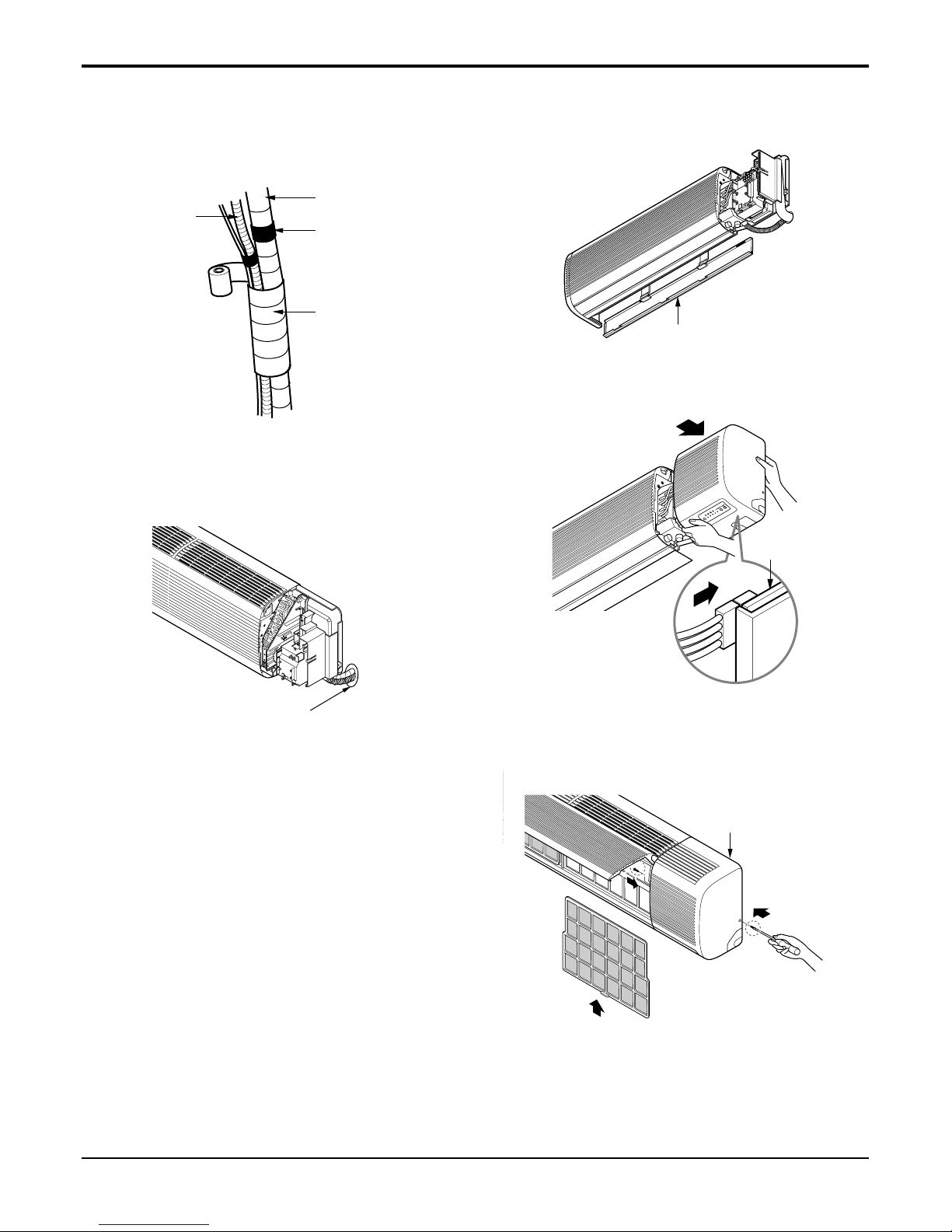
Press the lower left and right sides of the unit against the
installation plate until the hooks engage into their slots(clicking sound).
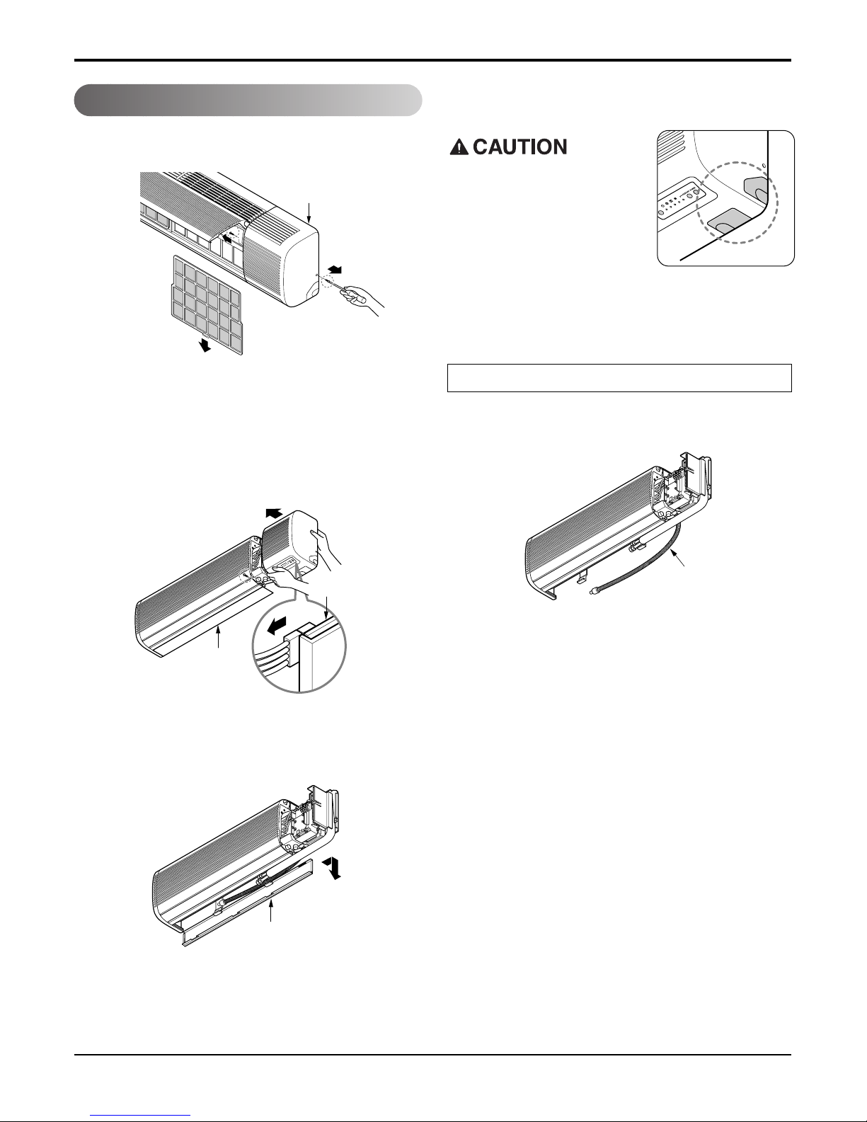
Connection of piping -- Indoor
1. Remove the 2 screws of right side panel.
2. Remove the front right side panel by the arrow.
■ The connector can be disconnected by pulling it
while pressing the connector's hook.
■ Remove the 1 screw for fixing lower panel.
3. Remove the lower panel by the arrow.
■ Take care not to scratch the wall and mat to
drop.
1. Route the indoor tubing and the drain hose in the
direction of rear left.
2. Insert the connecting cable into the indoor unit
from the outdoor unit through the piping hole.
■ Do not connect the cable to the indoor unit.
■ Make a small loop with the cable for easy
connection later.
Right side panel
Drain hose
Main PCB
Lower panel
Lower panel
For left rear piping
When install, make sure that
the remaining parts must be
removed clearly so as not to
damage the piping and drain
hose, especially power cord
and connecting cable.
- 18 -
Copyright ©2008 LG Electronics. Inc. All right reserved.
Only for training and service purposes
LGE Internal Use Only
Flaring work and connection of piping
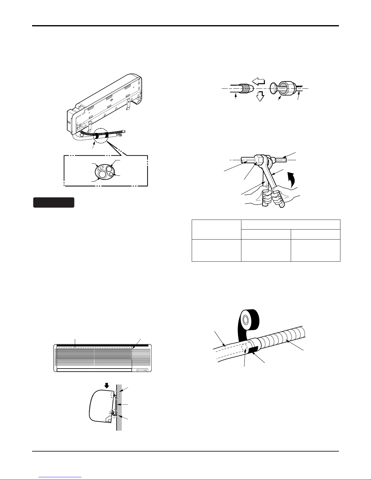
3. Tape the tubing, drain hose and the connecting
cable. Be sure that the drain hose is located at the
lowest side of the bundle. Locating at the upper side
can cause drain pan to overflow inside the unit.
3. Tape the tubing, drain hose and the connecting
cable. Be sure that the drain hose is located at the
lowest side of the bundle. Locating at the upper side
can cause drain pan to overflow inside the unit.
If the drain hose is routed inside the room, insulate
the hose with an insulation material* so that dripping
from "sweating"(condensation) will not damage furniture or floors.
*Foamed polyethylene or equivalent is recommend-
ed.
4. Indoor unit installation
■ Hook the indoor unit onto the upper portion of the
installation plate.(Engage the three hooks of the
rear top and rear lower of the indoor unit with the
upper edge and lower edge of the installation
plate.) Ensure that the hooks are properly seated
on the installation plate by moving it left and right.
NOTICE
5. Connecting the pipings to the indoor unit and drain
hose to drain pipe.
■ Align the center of the pipings and sufficiently
tighten the flare nut by hand.
■ Tighten the flare nut with a wrench.
■ When extending the drain hose at the indoor unit,
install the drain pipe.
Connecting
cable
Loop
Gas side
piping
Liquid side
piping
Drain hose
Installation
plate
Three upper
hooks
Installation plate
Indoor unit
Three lower
hooks
Setting line
Indoor unit tubing Flare nut Pipings
Connection pipe
Flare nut
Indoor unit tubing
Torque wrench
Spanner (fixed)
Vinyl tape(narrow)
Adhesive
Drain pipe
Indoor unit drain hose
Pipe Size[Torque]
Capacity
(Btu/h)
GAS LIQUID
30k 5/8"[6.6kg.m] 3/8"[4.2kg.m]
- 19 -
Copyright ©2008 LG Electronics. Inc. All right reserved.
Only for training and service purposes
LGE Internal Use Only
Flaring work and connection of piping
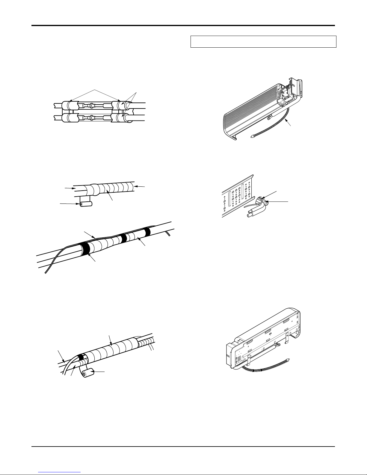
6. Wrap the insulation material around the connecting
portion.
■
Overlap the connection pipe insulation material and
the indoor unit pipe insulation material. Bind them
together with vinyl tape so that there is no gap.
■ Wrap the area which accommodates the rear pip-
ing housing section with vinyl tape.
■ Bundle the piping and drain hose together by
wrapping them with vinyl tape over the range within which they fit into the rear piping housing section.
1. Route the indoor tubing and the drain hose to the
required piping hole position.
2. Insert the piping, drain hose and the connecting
cable into the piping hole.
3. Insert the connecting cable into the indoor unit.
■ Don't connect the cable to the indoor unit.
■ Make a small loop with the cable for easy
connection later.
4. Tape the drain hose and the connecting cable.
• Connecting cable
Plastic bands
Insulation material
Drain hose
Drain pipe
Connecting cable
Vinyl tape(narrow)
Connection
pipe
Connecting cable
Vinyl tape
(wide)
Wrap with vinyl tape
Indoor
unit pipe
Pipe
Wrap with vinyl tape
Drain hose
Pipe
Vinyl tape(wide)
For right rear piping
- 20 -
Copyright ©2008 LG Electronics. Inc. All right reserved.
Only for training and service purposes
LGE Internal Use Only
Flaring work and connection of piping
5. Indoor unit installation
■ Hook the indoor unit onto the upper portion of the
installation plate.(Engage the three hooks of the
rear top and rear lower of the indoor unit with the
upper edge and lower edge of the installation
plate.) Ensure that the hooks are properly seated
on the installation plate by moving it left and right.
6. Connecting the pipings to the indoor unit and the
drain hose to drain pipe.
■ Align the center of the pipings and sufficiently
tighten the flare nut by hand.
■ Tighten the flare nut with a wrench.
■ When extending the drain hose at the indoor unit,
install the drain pipe.
7. Wrap the insulation material around the connecting
portion.
■
Overlap the connection pipe heat insulation and the
indoor unit pipe heat insulation material. Bind them
together with vinyl tape so that there is no gap.
■ Wrap the area which accommodates the rear
piping housing section with vinyl tape.
Installation
plate
Three upper
hooks
Installation plate
Indoor unit
Three lower
hooks
Setting line
Vinyl tape
Adhesive
Drain hose
Indoor unit drain hose
(narrow)
Plastic bands
Insulation material
Vinyl tape(narrow)
Connection
pipe
Connecting cable
Indoor
unit piping
Pipe
Vinyl tape
(wide)
Wrap with vinyl tape
Indoor unit tubing Flare nut Pipings
Torque wrench
Indoor unit tubing
Spanner (fixed)
Connection pipe
Flare nut
30k 5/8"[6.6kg.m] 3/8"[4.2kg.m]
Pipe Size[Torque]
Capacity
(Btu/h)
GAS LIQUID
- 21 -
Copyright ©2008 LG Electronics. Inc. All right reserved.
Only for training and service purposes
LGE Internal Use Only
Flaring work and connection of piping
■ Bundle the piping and drain hose together by
wrapping them with cloth tape over the range
within which they fit into the rear piping housing
section.
8. Reroute the pipings and the drain hose across the
back of the chassis.
9. Reinstall the parts to the original position.
■ Refix the lower panel to the original position.
■ Connect display conductor.
■ Refix the front right side panel to the original
position with the two screws.
Drain hose
Vinyl tape(narrow)
Pipe
Wrap with
vinyl tape(wide)
Lower panel
Main PCB
Right side panel
Piping for
passage through
piping hole
- 22 -
Copyright ©2008 LG Electronics. Inc. All right reserved.
Only for training and service purposes
LGE Internal Use Only
Flaring work and connection of piping
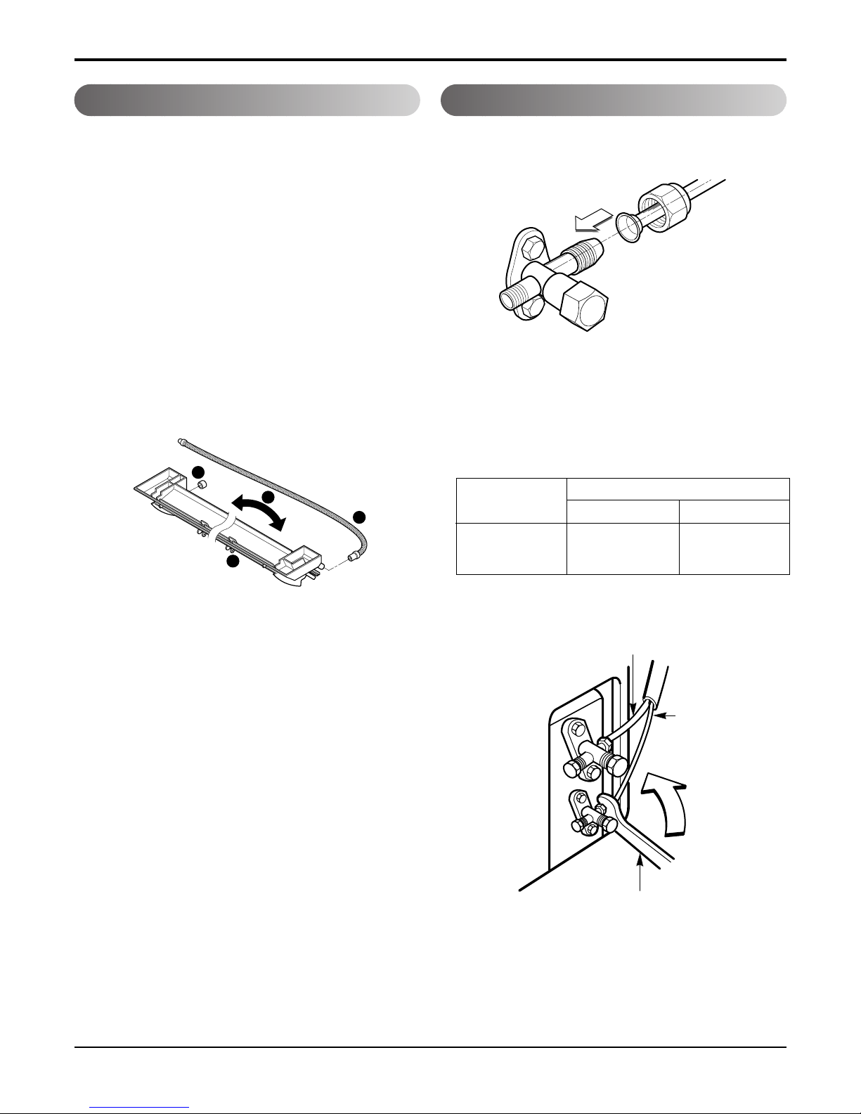
■ The drain hose can be connected at two different
positions. Use the most convenient position and, if
necessary, exchange the position of the drain
pan, rubber cap and the drain hose.
➊ Drain pan
➋ Rubber cap
➌ Drain hose
➍ Exchange if necessary
■ Remove the drain hose.
■ Securely insert both the rubber plug and drain
hose into the drain outlets.
Be sure the rubber the cap is securely fastened
so that there is no leakage.
1. Align the center of the pipings and sufficiently
tighten the flare nut by hand.
2. Finally, tighten the flare nut with torque wrench
until the wrench clicks.
■ When tightening the flare nut with torque wrench,
ensure the direction for tightening follows the
arrow on the wrench.
1
2
3
4
Outdoor unit
Gas side piping
(Bigger diameter)
Liquid side
piping
(Smaller
diameter)
Torque wrench
30k 5/8"[6.6kg.m] 3/8"[4.2kg.m
Pipe Size[Torque]
Capacity
(Btu/h)
GAS LIQUID
Connection of the drain hose Connection of piping-Outdoor
- 23 -
Copyright ©2008 LG Electronics. Inc. All right reserved.
Only for training and service purposes
LGE Internal Use Only
Connect the cable to the Indoor unit.
Connecting the cable between indoor unit and outdoor unit
Connecting the cable between indoor unit and outdoor unit
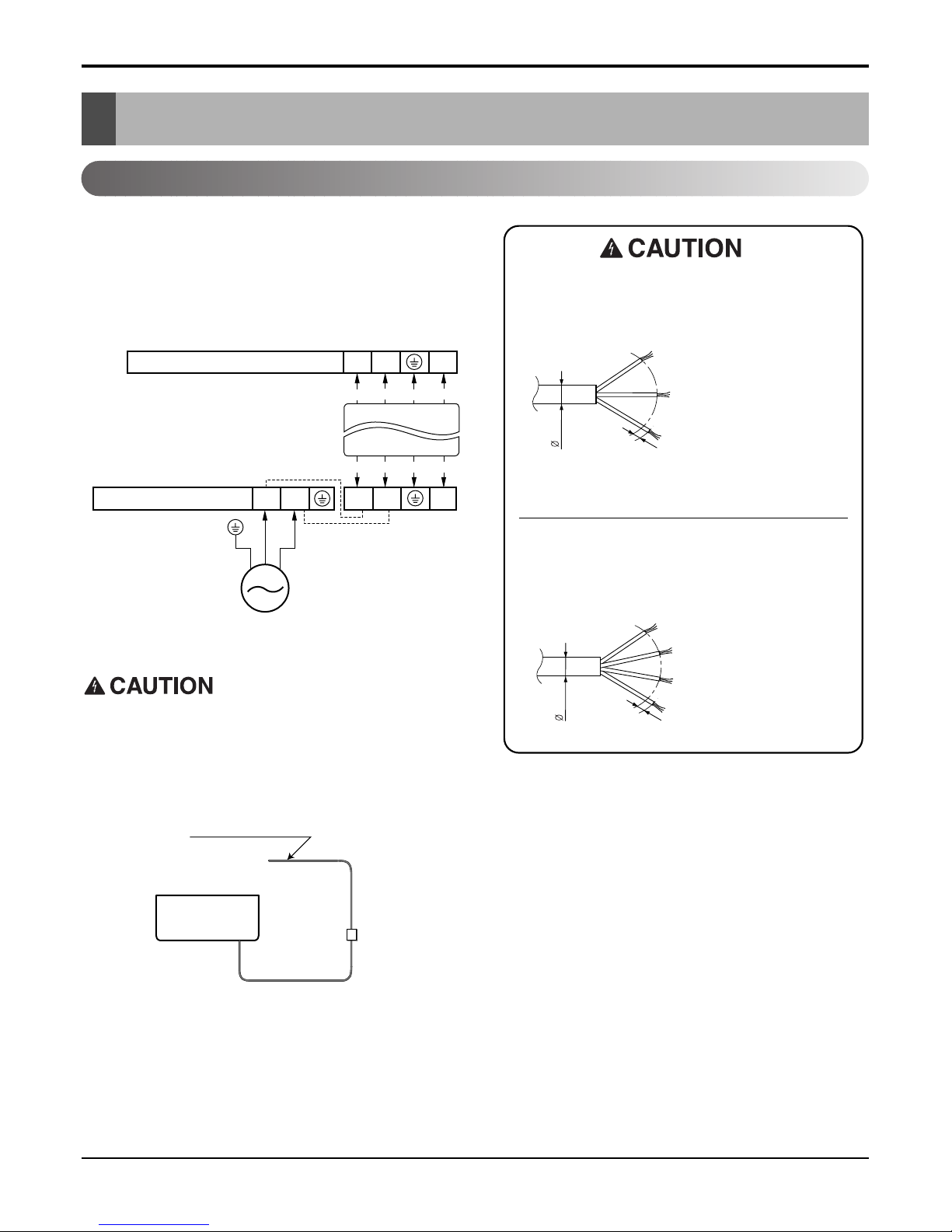
■
Connect the cable to the indoor unit by connecting the wires to the terminals on the control
board individually according to the outdoor unit
connection.(Ensure that the color of the wires of the
outdoor unit and the terminal No. are the same as
those of the indoor unit.)
2(N)Terminals on the indoor unit 1(L) 3
2(N)1(L) 3
Terminals on the outdoor unit
Color of Wires
POWER INPUT
Color of Wires
2(N)1(L)
RED
G/Y
BROWN
BLUE
RED
G/Y
BROWN
BLUE
Air
Conditioner
Main power source
The power cord connected to the outdoor unit
should be complied with the following
specifications (Rubber insulation, type H05RN-F
approved by HAR or SAA).
The connecting cable connected to the indoor
and outdoor unit should be complied with the
following specifications (Rubber insulation, type
H07RN-F approved by HAR or SAA).
8.5mm
20mm
GN/YL
NORMAL
CROSS-SECTIONAL
AREA 2.5mm
2
20mm
GN/YL
NORMAL
CROSS-SECTIONAL
AREA 0.75mm
2
7.5mm
30k
If a power plug is not to be used,
provide a circuit breaker between
power source and the unit as
shown below.
- 24 -
Copyright ©2008 LG Electronics. Inc. All right reserved.
Only for training and service purposes
LGE Internal Use Only
Connecting the cable between indoor unit and outdoor unit
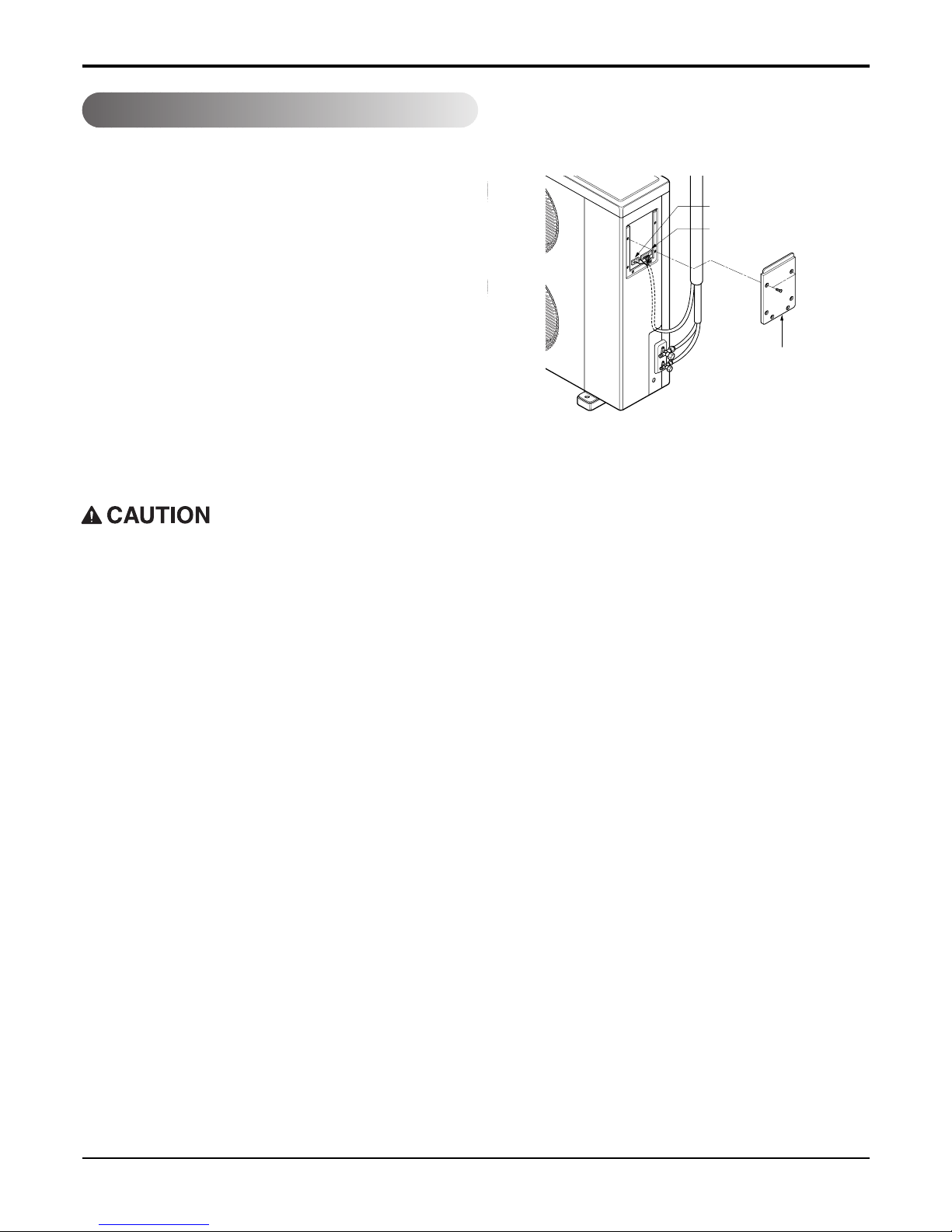
Connect the cable to the outdoor unit
1. Remove the control cover from the unit by loosening the screw.
Connect the wires to the terminals on the control
board individually.
2. Secure the cable onto the control board with the
cord clamp.
3. Refix the control cover to the original position with
the screw.
4. Use a recognized circuit breaker 30A (30k, 32k),
35A (36k, 38k) between the power source and the
unit. A disconnecting device to adequately disconnect all supply lines must be fitted.
Main terminal board
Control terminal board
Cover control
After the confirmation of the above conditions, prepare the wiring as follows:
1) Never fail to have an individual power circuit specifically for the air conditioner. As for the method
of wiring, be guided by the circuit diagram posted on the inside of control cover.
2) The screw which fasten the wiring in the casing of electrical fittings are liable to come loose from
vibrations to which the unit is subjected during the course of transportation. Check them and make
sure that they are all tightly fastened. (If they are loose, it could cause burn-out of the wires.)
3) Specification of power source.
4) Confirm that electrical capacity is sufficient.
5) See to that the starting voltage is maintained at more than 90 percent of the rated voltage marked on
the name plate.
6) Confirm that the cable thickness is as specified in the power source specification.
(Particularly note the relation between cable length and thickness. (Refer to page 32))
7) Always install an earth leakage circuit breaker in a wet or moist area.
8) The following would be caused by voltage drop.
• Vibration of a magnetic switch, which will damage the contact point, fuse breaking, disturbance of the nor-
mal function of the overload.
9) The means for disconnection from a power supply shall be incorporated in the fixed wiring and have
an air gap contact separation of at least 3mm in each active(phase) conductors.
 Loading...