

LG AS-W1863 Series, AS-W2463 Series Svc Manual

Universal Air Conditioner
SVC MANUAL(Exploded View)
MODEL : AS-W1863_ Series
AS-W2463_ Series
CAUTION
Before Servicing the unit, read the safety precautions in General SVC manual.
Only for authorized service personnel.
Internal Use Only
http://biz.lgservice.com

- 2 -
Copyright ©2009 LG Electronics. Inc. All right reserved.
Only for training and service purposes
LGE Internal Use Only
Air Conditioner Service Manual
TABLE OF CONTENTS
LG Model Name ...............................................................................................................................................3
Safety Precautions..........................................................................................................................................5
Dimensions .....................................................................................................................................................9
Symbols Used in this Manual.....................................................................................................................9
Indoor Unit..................................................................................................................................................9
Outdoor Unit.............................................................................................................................................10
Product Specifications ................................................................................................................................11
Installation .....................................................................................................................................................13
Select the Best Location .........................................................................................................................13
Piping Length and Elevation.....................................................................................................................14
Fixing Installation Plate ............................................................................................................................14
Drill a Hole in the Wall..............................................................................................................................15
Flaring Work.............................................................................................................................................15
Connection of Piping ................................................................................................................................16
Connecting the Cables.............................................................................................................................22
Checking the Drainage.............................................................................................................................24
Forming the Piping ...................................................................................................................................25
Air Purging ...............................................................................................................................................26
Test Running ............................................................................................................................................28
Functions .......................................................................................................................................................30
Operation .......................................................................................................................................................33
Disassembly ..................................................................................................................................................47
Indoor Unit................................................................................................................................................47
Schematic Diagram.......................................................................................................................................50
Wiring Diagram.........................................................................................................................................50
Components Location ..............................................................................................................................52
Troubleshooting Guide .................................................................................................................................56
Refrigeration Cycle Diagram ....................................................................................................................56
Pipe Length and the Elevation .................................................................................................................57
2-way, 3-way Valve ...................................................................................................................................58
Cycle Parts...............................................................................................................................................65
Self-diagnosis Function............................................................................................................................66
Electronic Parts ........................................................................................................................................68
Exploded View...............................................................................................................................................79
Indoor Unit................................................................................................................................................79
Outdoor Unit.............................................................................................................................................80
- 3 -
Copyright ©2009 LG Electronics. Inc. All right reserved.
Only for training and service purposes
LGE Internal Use Only
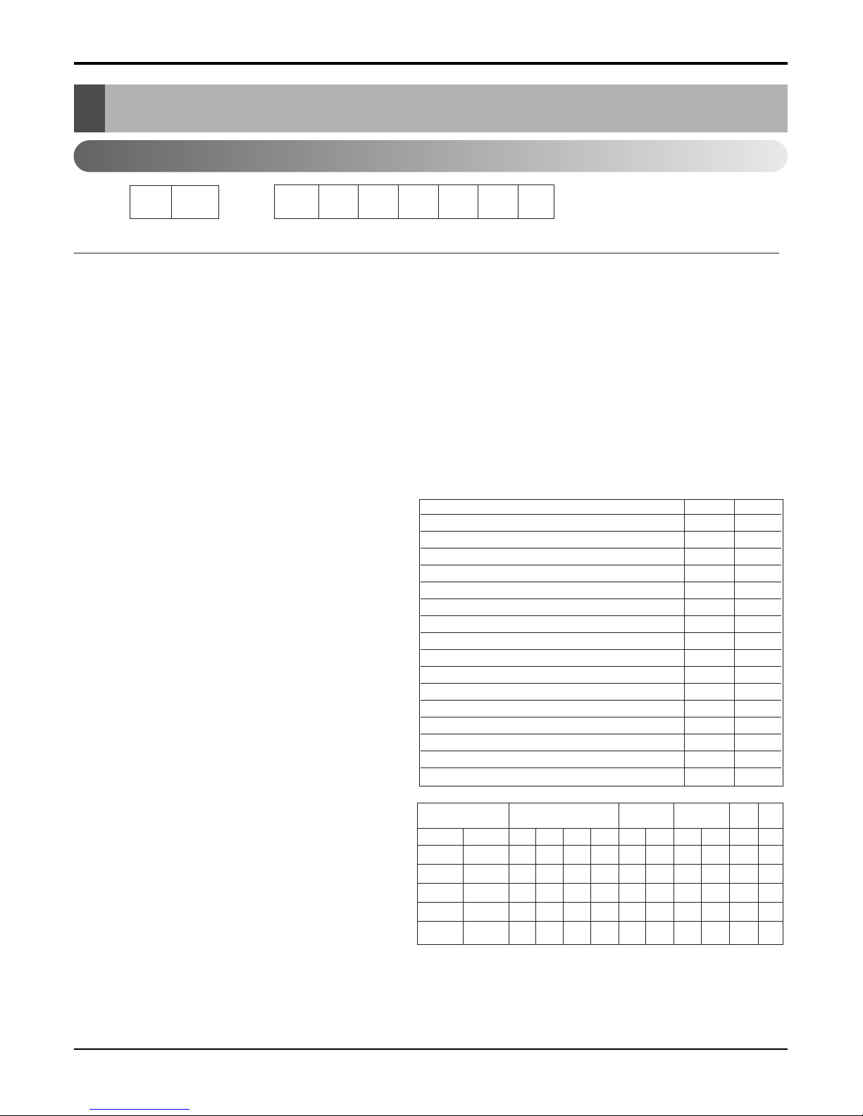
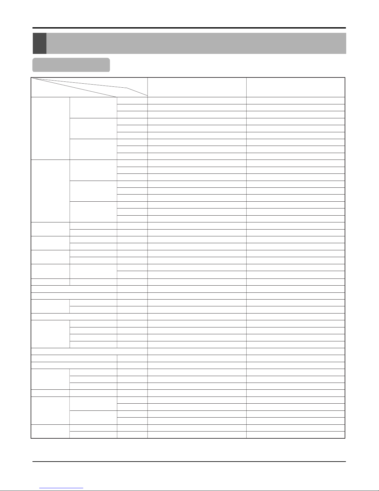
LG Model Name
12
3456789
Code Type Code of Model Meaning
1,2 Type of Airconditioner A~Z LS: LG Split Type Airconditioner
3 Chassis A~Z Name of toll of Unit
Ex. LS-R ➔ S R Chassis
4,5 Capacity(Btu/h) 1~9 Cooling/Heating Capacity
Ex. "09" ➔ 9,000Btu/h
6 Electric Range 1~9 Electric Standard
1 ➔ 115V/60Hz 6 ➔ 220~240V/50Hz
2 ➔ 220V/60Hz 7 ➔ 110V, 50/60Hz
3 ➔ 208~230V/60Hz 8 ➔ 380~415V/50Hz
5 ➔ 200~220V/50Hz 9 ➔ 380~415V/60Hz
7 Serial No. 0~9
A~Z
8 Cooling/Heating A~Z
9 LG/OEM Brand A~Z L: LG Brand M: 1st OEM Brand
G: 2nd LG Brand N: 2nd OEM Brand
-
Basic A 0
Plasma Filter B 1
Auto Swing
+ Plasma Filter C 2
Telephone + LED Display D 3
Telephone + LCD Display E 4
Auto Swing
+ Plasma Filter + Telephone + LCD
F5
Low Ambient + Ambient/change G 6
Plasma Filter + Low Ambient + Ambient/change
H7
Internet J 8
Auto Swing + Plasma Filter + Oxygen Generator
K9
Auto Swing + Soft Start ZL
Auto Swing + Star Rating M Y
Auto Swing + Star Rating + Plasma Filter N X
Auto Swing + Soft Start + Star Rating P W
Auto Swing + Soft Start + Star Rating 4 + Plasma
QV
Auto Swing + Telephone + LCD R U
Auto Swing + Telephone + LCD + Soft Start
ST
C/O
C
A
D
G
K
H/P
H
B
E
J
L
E/H+C/O
X
5
7
-
-
E/H+H/P
Y
6
8
-
-
C/O
F
M
Q
-
-
H/P
R
P
S
-
-
C/O
V
W
1
3
H/P
N
Y
2
4
H/PTH/P
U
INDOOR
BASIC
BASIC
PLASMA
PLASMA
GOLD FIN
OUTDOOR
BASIC
GOLD FIN
GOLD FIN
BASIC
GOLD FIN
UNIT
R22
HFC R22+AC INV.
HFC+AC
INV.
HFC+DC
INV.
2002
- 4 -
Copyright ©2009 LG Electronics. Inc. All right reserved.
Only for training and service purposes
LGE Internal Use Only
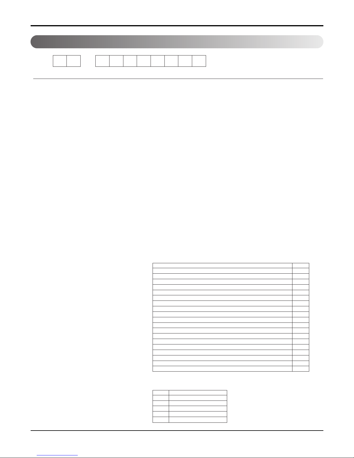
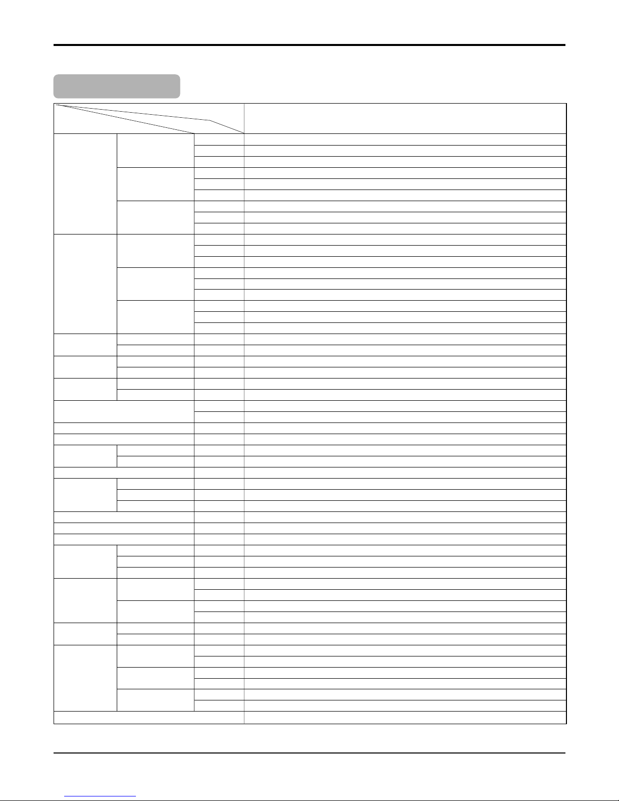
12 - 345678910
Code Type Code of Model Meaning
1 Producing Center, A~Z L: Chang-won R22 N: India
Refrigerant A: Chang-won R410A Z: Brazil
C: Chang-won R407C D: Indonesia
T: China M: Mexico
K: Turkey R22 V: Vietnam
E: Turkey R410A S: Out Sourcing
H: Thailand
2 Product Type A~Z S: Split Type Air Conditioner
3 Cooling/Heating/Inverter A~Z C: Cooling only
H: Heat pump
X: C/O + E/Heater
Z: H/P + E/Heater
V: AC Inverter C/O
N: AC Inverter H/P
Q: DC Inverter C/O
W: DC Inverter H/P
4, 5 Capacity 0~9 Cooling/Heating Capacity
Ex. "09" → 9,000 Btu/h
6 Electric Range 1~9 1: 115V/60Hz, A: 220V, 50Hz, 3Phase
A~Z 2: 220V/60Hz B: 208~230V, 60Hz, 3Phase
3: 208-230V/60Hz C: 575V, 50Hz, 3Phase
5: 200-220V/50Hz D: 440~460, 60Hz, 3Phase
6: 220-240V/50Hz E: 265V, 60Hz
7: 110V, 50/60Hz F: 200V, 50/60Hz
8: 380-415V/50Hz
9: 380-415V/60Hz
7 Chassis A~Z Name of Chassis of Unit
Ex. LSP → SP Chassis
8 Look A~Z Look,
Color (Artcool Model)
9 Function A~Z
10 Serial No. 1~9 LG Model De
* ARTCOOL COLOR
velopment Serial No.
Basic A
Basic+4Way B
Plasma Filter C
Plasma Filter+4 Way D
Tele+LCD E
Tele+LCD+Nano plasma+4Way F
Nano Plasma F+(A/changeove)+A/clean+Low A G
Nano Plasma F+(A/changeove)+A/clean+4way+Low A H
Tele+LED+4way I
Internet J
Plasma F+4Way+Oxy generator K
Nano Plasma F+(A/changeove)+A/clean L
Nano Plasma F+(A/changeove)+A/clean+4way M
Nano Plasma F+(A/changeove)+A/clean+PTC N
Nano Plasma F+(A/changeove)+Autoclean+4way+PTC P
Nano Plasma F+(A/changeove)+A/clean+4way+Low A+PTC Q
Negative ION+A/Clean R
(Nano)Plasma+Negative ION+A/Clean S
4way+(Nano)Plasma F+Negative ION+Healthy dehumidification+A/Clean
T
Nano Plasma F+4Way+(A/changeove)+A/clean+ U
R Mirror
W White
B Blue
D Wood
M Metal
C Cherry
2003~2004
- 5 -
Copyright ©2009 LG Electronics. Inc. All right reserved.
Only for training and service purposes
LGE Internal Use Only
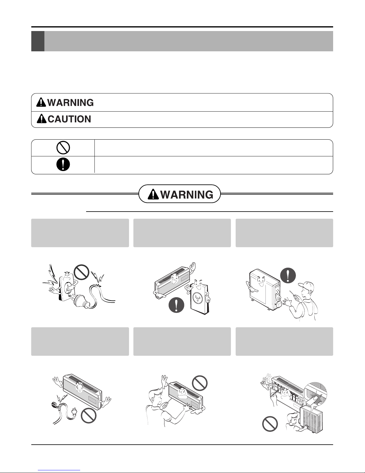
Safety Precautions
Safety Precautions
To prevent injury to the user or other people and property damage, the following instructions must
be followed.
■ Incorrect operation due to ignoring instruction will cause harm or damage. The seriousness is
classified by the following indications.
■ Meanings of symbols used in this manual are as shown below.
This symbol indicates the possibility of death or serious injury.
This symbol indicates the possibility of injury or damage to properties only.
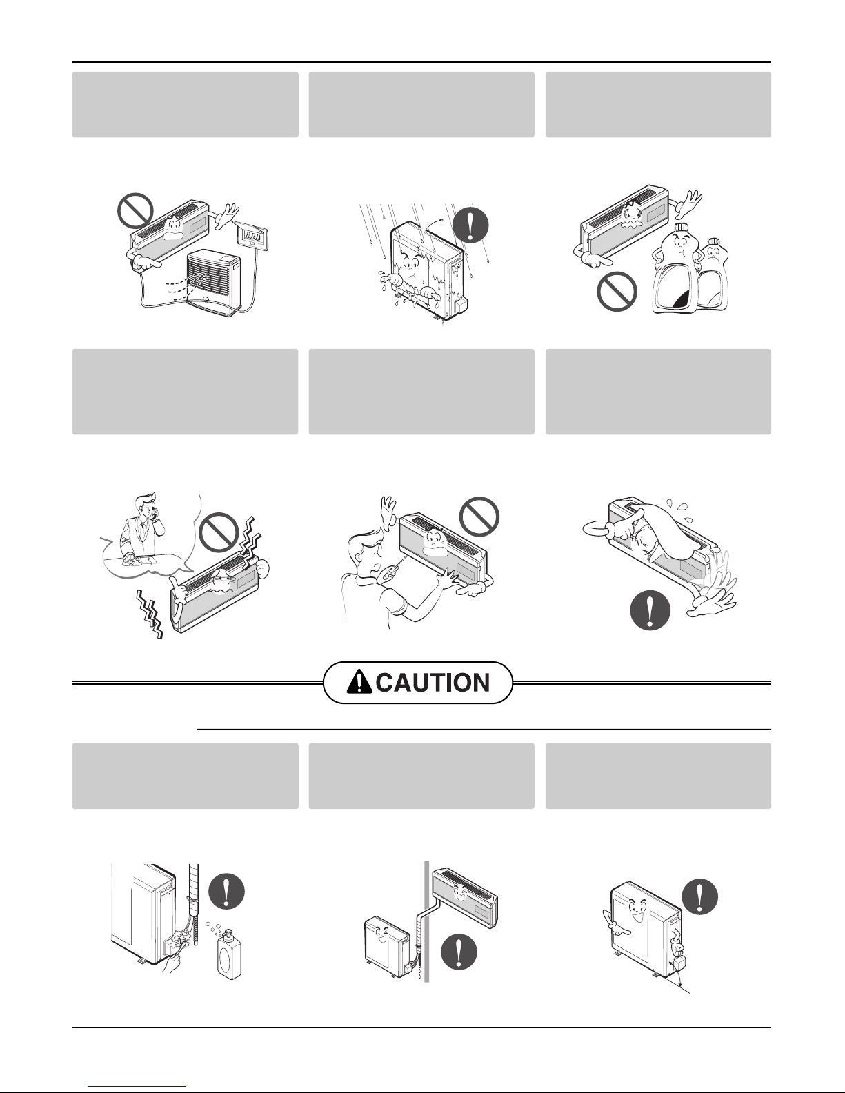
Be sure not to do.
Be sure to follow the instruction.
Do not use damaged power
cords, plugs, or a loose socket.
• There is risk of fire or electric
shock.
Always use the power plug
and socket with the ground
terminal.
• There is risk of electric shock.
Install the panel and the cover
of control box securely.
• There is risk of fire or electric
shock.
■ Installation
Do not modify or extend the
power cord.
• There is risk of fire or electric
shock.
Do not install, remove, or reinstall the unit by yourself
(customer).
• There is risk of fire, electric shock,
explosion or injury.
Be cautious when unpacking
and installing the product.
• Shape edges could cause injury.
Be especially careful of the sharp
edges.
- 6 -
Copyright ©2009 LG Electronics. Inc. All right reserved.
Only for training and service purposes
LGE Internal Use Only
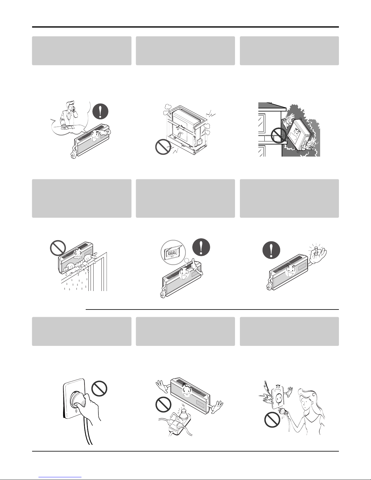
Safety Precautions
For installation, always contact the dealer or an
Authorized Service Center.
• There is risk of fire, electric shock,
explosion, or injury.
Do not install the product on a
defective installation stand.
• It may cause injury, accident, or
damage to the
product.
Be sure the installation area
does not deteriorate with age.
• If the base collapses, the air conditioner could fall with it, causing
property damage, product failure,
and personal injury.
Do not let the air conditioner
run for a long time when the
humidity is very high and a
door or a window is left open.
• Moisture may condense and wet or
damage furnishings.
Always install a dedicated
circuit and breaker.
• Improper wiring or installation may
cause fire or electric shock
Use the correctly rated breaker or fuse.
• There is risk of fire or electric
shock.
■ Operation
Do not turn the air-conditioner
ON or OFF by plugging or
unplugging the power plug.
• There is risk of fire or electric
shock.
Use a dedicated outlet for this
appliance.
• There is risk of fire or electric
shock.
Grasp the plug to remove the
cord from the outlet. Do not
touch it with wet hands.
• There is risk of fire or electric
shock.
- 7 -
Copyright ©2009 LG Electronics. Inc. All right reserved.
Only for training and service purposes
LGE Internal Use Only
Safety Precautions
■ Installation
Unplug the unit if strange
sounds odors, or smoke
comes from it.
• There is risk of fire, failure of the
product, and/or electric shock.
Do not open the inlet grill of the
product during operation. (Do
not touch the electrostatic filter,
if the unit is so equipped.)
• There is risk of physical injury,
electric shock, or product.
Be cautious that water could
not enter the product.
• There is risk of fire, electrical shock
or product damage.
Do not place a heater or other
appliances near the power
cable.
• There is risk of fire, failure of the
product, and/or electric shock.
Do not allow water to run into
electric part.
• There is risk of fire, failure of the
product, and/or electric shock.
Do not store of use flammable
gas or combustibles near the
air conditioner.
• There is risk of fire or failure of
product.
Wax
Thinner
Always check for gas(refrigerant) leakage after installation
or repair of product.
• Low refrigerant levels may cause
failure of product.
Install the drain hose to
ensure that water is drained
away properly.
• A bad connection may cause water
leakage.
Keep level even when
installing the product.
• To avoid vibration or water leakage.
90˚
- 8 -
Copyright ©2009 LG Electronics. Inc. All right reserved.
Only for training and service purposes
LGE Internal Use Only
Safety Precautions
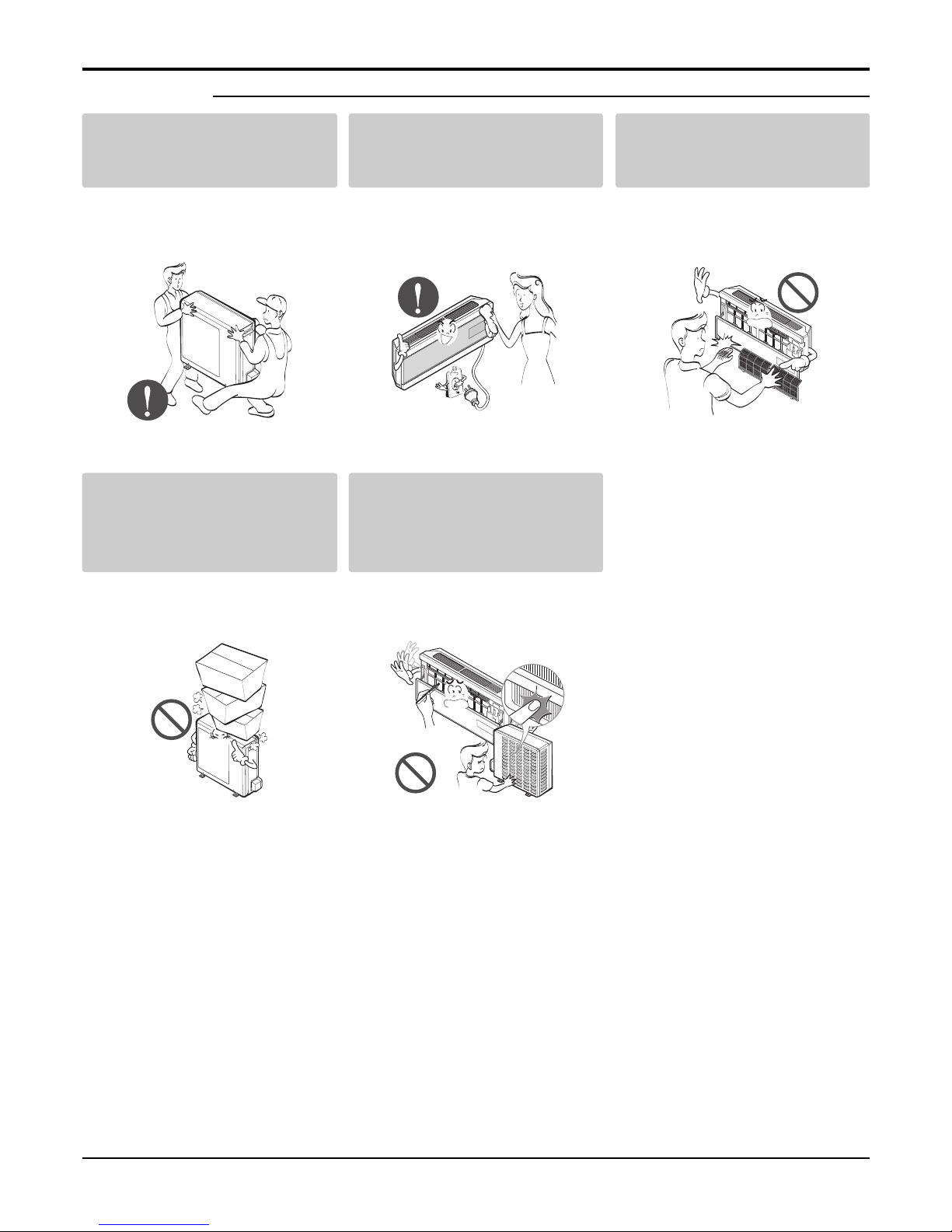
■ Operation
Use two or more people to lift
and transport the air conditioner
• Avoid personal injury.
Use a soft cloth to clean. Do
not use harsh detergents, solvents, etc.
• There is risk of fire, electric shock
or damage to the plastic parts of
the product.
Do not touch the metal parts of
the product when removing the
air filter. They are very sharp!
• There is risk of personal injury.
Do not step on or put anything
on the product. (outdoor unit)
• There is risk of personal injury and
failure of product.
Do not insert hands or other
objects through the air inlet or
outlet while the air conditioner
is plugged in.
• There are sharp and moving parts
that could cause personal injury.
Dimensions
Dimensions
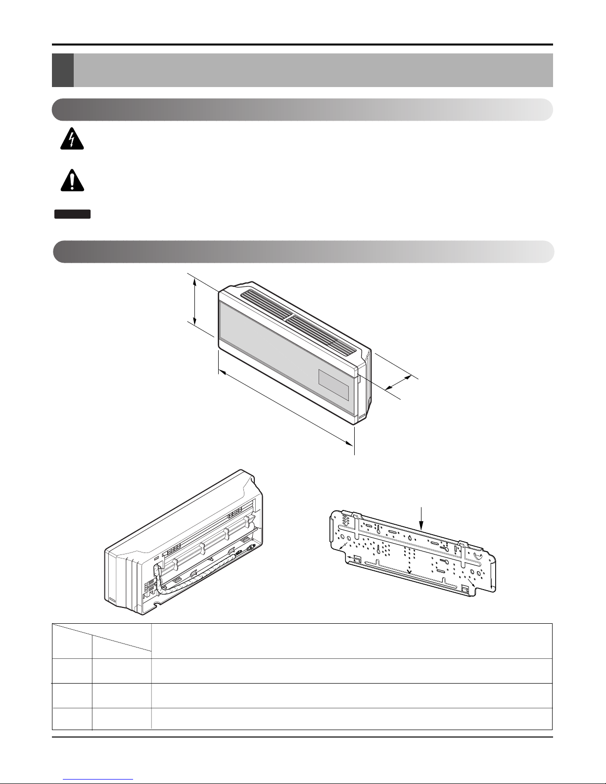
Indoor Unit
This symbol alerts you to the risk of electric shock.
This symbol alerts you to hazards that could cause harm to the
air conditioner.
This symbol indicates special notes.
NOTICE
Symbols Used in this Manual
Installation plate
D
H
W
MODEL
DIM Unit
W mm 1170
H mm 315
D mm 173
18k, 24k Btu Series
- 9 -
Copyright ©2009 LG Electronics. Inc. All right reserved.
Only for training and service purposes
LGE Internal Use Only
- 10 -
Copyright ©2009 LG Electronics. Inc. All right reserved.
Only for training and service purposes
LGE Internal Use Only
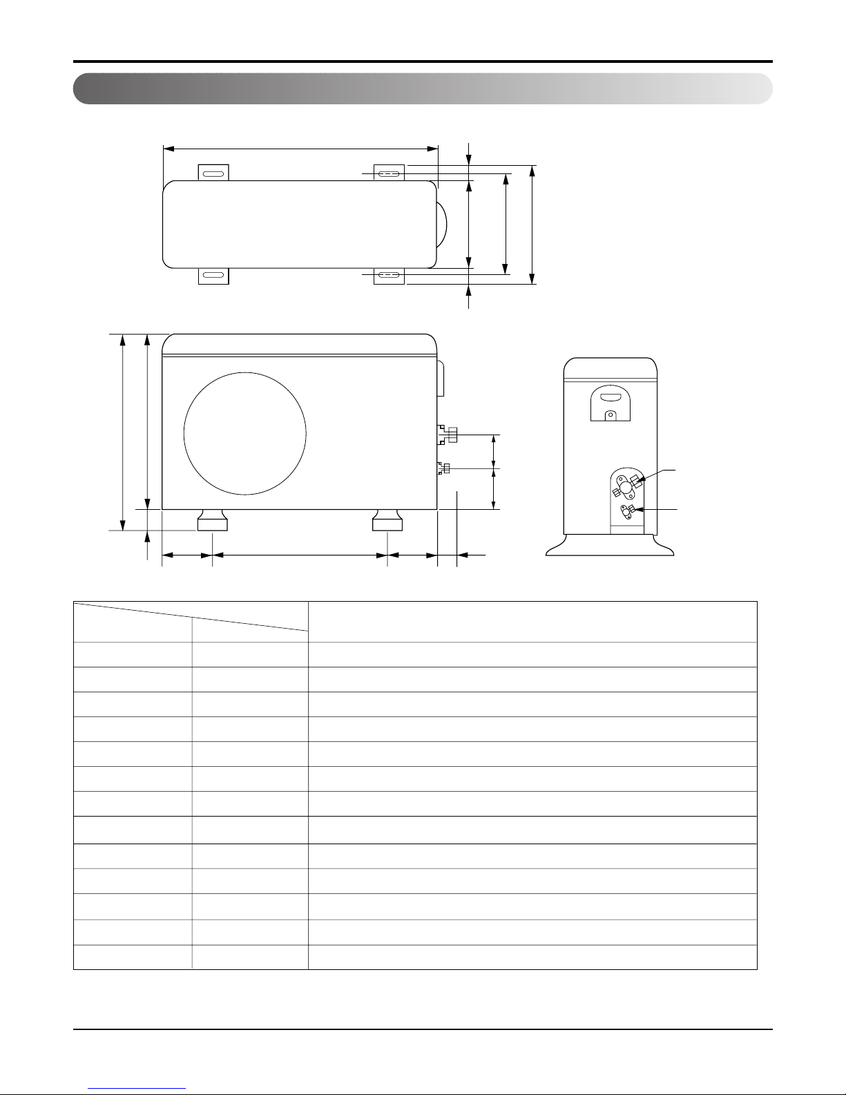
Outdoor Unit
Dimensions
W
L7 L6 L8 L9
D
L1
L2
L3
L10L11
L4L5
H
Gas side
Liquid side
MODEL
18k, 24k Btu Series
DIM unit
W mm 870
H mm 655
D mm 320
L1 mm 370
L2 mm 340
L3 mm 25
L4 mm 630
L5 mm 25
L6 mm 546
L7 mm 162
L8 mm 162
L9 mm 54
L10 mm 74.5
- 11 -
Copyright ©2009 LG Electronics. Inc. All right reserved.
Only for training and service purposes
LGE Internal Use Only
Product Specifications
Table-1
Product Specifications
Model Name
Item Unit
W
MIN kcal/h.(W)
Btu/h.
W
Cooling Capacity Type kcal/h.(W)
Btu/h.
W
Max kcal/h.(W)
Btu/h.
W
MIN kcal/h.(W)
Btu/h.
W
Heating Capacity Type kcal/h.(W)
Btu/h.
W
Max kcal/h.(W)
Btu/h.
Power Input Cooling W
Heating W
Running Current Cooling A
Heating A
Starting Current Cooling A
Heating
A
EER
Btu/h.W
COP
W/W
W/W
Power Supply Ø,V,Hz
Power Factor %
Air Circulation Indoor,Max m3/min(CFM)
Outdoor,Max m3/min(CFM)
Moisture Removal l/h.(pts/h.)
Noise Level Indoor,High dB(A) 3
(Sound Med. dB(A) 3
Pressure,1m) Low dB(A) 3
Outdoor,Max dB(A) 3
Refrigerant(R410A)Charge
Power Cord AWG#:P*mm
2
Connecting Cable AWG#:P*mm
2
Connecting Tube Liquid Side mm(in)
(Ø. Socket Flare) Gas Side mm(in)
Length,std m(in)
Drain Hose (O.D , I.D) mm(in)
Indoor mm
Dimension inch
(W*H*D) Outdoor mm
inch
Net Weight Indoor kg(lbs)
Outdoor kg(lbs)
AS-W1863_ Series AS-W2463_ Series
1,612
1,386
5,500
5,274
4,536
18,000
5,831
5,015
19,900
1,670
1,436
5,700
6,065
5,216
20,700
6,739
5,796
23,000
4,430
3,810
15,120
7,032
6,048
24,000
7,735
6,653
26,400
4,190
3,604
14,300
7,946
6,834
27,120
8,351
7,182
28,500
1,630 2,600
1,890 2,800
7.5 11.5
8.5 12.5
7.5 11.5
8.5 12.5
3.24 2.71
11.04 9.23
3.21 2.84
1,220-240,50 1,220-240,50
96 98
14.15(499) 16.64(587)
42(1483) 45(1587)
2.4(5.1) 2.4(5.1)
43/43 45/45
40/40 41/41
37/37 36/37
56/57 56/57
1200(42.3) 1490(52.6)
16:3*2.5 16:3*2.5
16:4*2.5 16:4*2.5
6.35(1/4) 9.52(3/8)
12.7(1/2) 15.88(5/8)
7.5(295) 7.5(295)
21.5,16.0(0.85,0.63) 21.5,16.0(0.85,0.63)
1170*315*173
46.1*12.4*6.8
870*655*320
34.3*25.8*12.6
13(28.7)
60(132.3)
1170*315*173
46.1*12.4*6.8
870*655*320
34.3*25.8*12.6
13(28.7)
60(132.3)
- 12 -
Copyright ©2009 LG Electronics. Inc. All right reserved.
Only for training and service purposes
LGE Internal Use Only
Buyer Models
Item Unit
Cooling Capacity Min W
kcal/h
Btu/h
Rating W
kcal/h
Btu/h
Max W
kcal/h
Btu/h
Heating Capacity Min W
kcal/h
Btu/h
Rating W
kcal/h
Btu/h
Max W
kcal/h
Btu/h
Power Input Cooling W
Heating W
Running Current Cooling A
Heating A
Starting Current Cooling A
Heating A
EER W/W
Btu/h.W
COP W/W
Power Supply Ø,V,Hz
Air Circulation Indoor,Max m3/min (l/s)
Outdoor,Max m3/min (l/s)
Moisture Removal l/h (pts/h)
Noise Level Indoor,High dB(A)±3
(Sound Low dB(A)±3
Pressure,1m) Outdoor,Max dB(A)±3
Refrigerant (R410A) Charge g (oz)
Power Cord P*mm
2
Connecting Cable P*mm
2
Connecting Tube Liquid Side mm (in)
(Ø. Socket Flare) Gas Side mm (in)
Length,std m (in)
Dimension Indoor mm
(W*H*D) in.
Outdoor mm
in.
Net Weight Indoor kg (lbs)
Outdoor kg (lbs)
Energy Labeling Capacity Cooling
Heating
Energy Consumption Cooling
Heating
Star Rating Cooling
Heating
Tool (IN/OUT)
1,612
1,386
5,497
5,260
4,520
17,937
5,831
5,015
19,884
1,670
1,436
5,695
6,000
5,156
20,460
6,739
5,796
22,980
1,690
2,050
7.5
8.5
7.5
8.5
3.11
10.61
2.93
1,220-240,50
14.1 (235)
42 (700)
2.4 (5.1)
41
35
54
1,200 (42.3)
3*2.5 (20A)
4*1.5
6.35 (1/4)
12.7 (1/2)
7.5 (295)
1170*315*173
46*12.4*6.8
870*655*320
34.3*25.8*12.6
13 (28.7)
60 (132.3)
5.26
6.00
1.69
2.05
4.0
3.0
S3+UE
AS-W1863RH1
Table-2
Installation
Installation
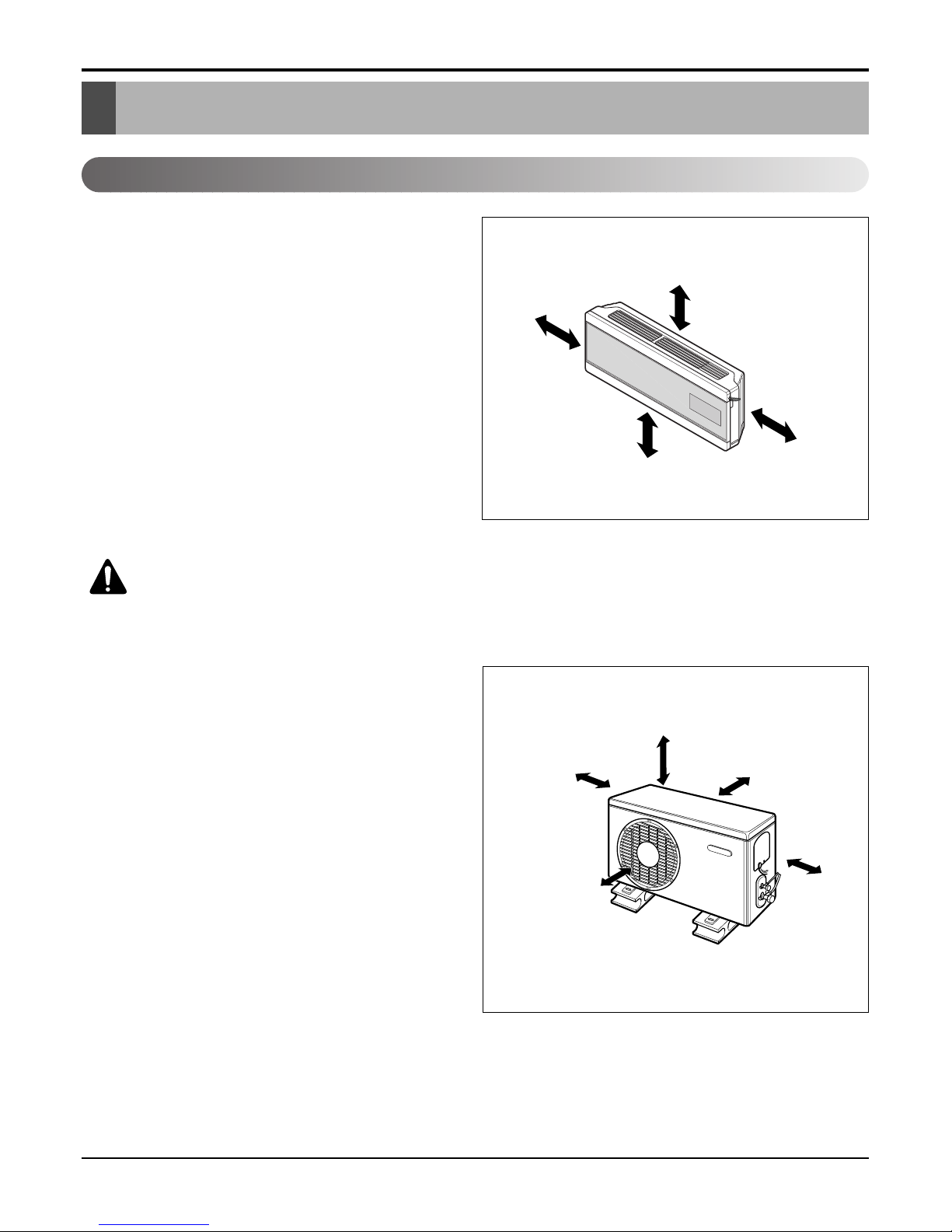
Indoor unit
1. Do not have any heat or steam near the unit.
2. Select a place where there are no obstacles in front
of the unit.
3. Make sure that condensation drainage can be conveniently routed away.
4. Do not install near a doorway.
5. Ensure that the interval between a wall and the left
(or right) of the unit is more than 50cm. The unit
should be installed as high as possible on the wall,
allowing a minimum of 10cm from ceiling.
6. Use a stud finder to locate studs to prevent unnecessary damage to the wall.
Outdoor unit
1. If an awning is built over the unit to prevent direct
sunlight or rain exposure, make sure that heat radiation from the condenser is not restricted.
2. Ensure that the space around the back and sides is
more than 10cm. The front of the unit should have
more than 70cm of space.
3. Do not place animals and plants in the path of the
warm air.
4. Take the weight of the air conditioner into account
and select a place where noise and vibration are minimum.
5. Select a place where the warm air and noise from the
air conditioner do not disturb neighbors.
Select the best Location
More than 10cm
More than
5cm
More than 2.3m
More than
5cm
CAUTION: Install the indoor unit on the wall where the height from the
floor is more than 2 meters.
More than 10cm More than 10cm
More
than 60cm
More than 60cm
More than 70cm
- 13 -
Copyright ©2009 LG Electronics. Inc. All right reserved.
Only for training and service purposes
LGE Internal Use Only
- 14 -
Copyright ©2009 LG Electronics. Inc. All right reserved.
Only for training and service purposes
LGE Internal Use Only
Installation
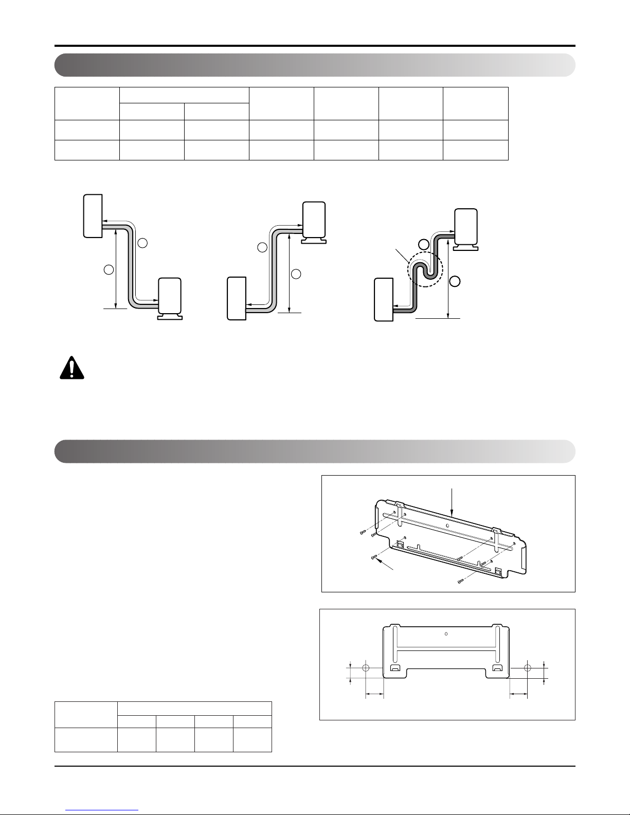
Piping Length and Elevation
18k 1/2" 1/4" 4 or 5 7 15 20
24k 5/8" 3/8" 4 or 5 7 15 30
Pipe Size
Capacity
(Btu/h)
GAS LIQUID
Max.
Length A (m)
Additional
Refrigerant (g/m)
Max.
Elevation B (m)
Standard
Length (m)
Outdoor unit
Indoor unit
A
B
Outdoor unit
Indoor unit
A
B
A
Oil trap
Outdoor unit
Indoor unit
B
If piping length is more than 5m
CAUTION: Capacity is based on standard length and maximum allowance length is
on the basis of reliability.
Oil trap should be installed every 5~7 meters.
The wall you select should be strong and solid
enough to prevent vibration
1. Mount the installation plate on the wall with
type "A" screws. If mounting the unit on a concrete
wall, use anchor bolts.
• Mount the installation plate horizontally by aligning
the centerline using a level.
2. Measure the wall and mark the centerline. It is also
important to use caution concerning the location of
the installation plate-routing of the wiring to power
outlets is through the walls typically. Drilling the
hole through the wall for piping connections must
be done safely.
Fixing Installation Plate
Installation Plate
Type "A" screw
(S3)
Right rear piping
B
A
D
C
Installation plate
ABCD
S3
58 3 292 3
(18k~24k)
CHASSIS
(Grade)
Distance (mm)
- 15 -
Copyright ©2009 LG Electronics. Inc. All right reserved.
Only for training and service purposes
LGE Internal Use Only
Installation
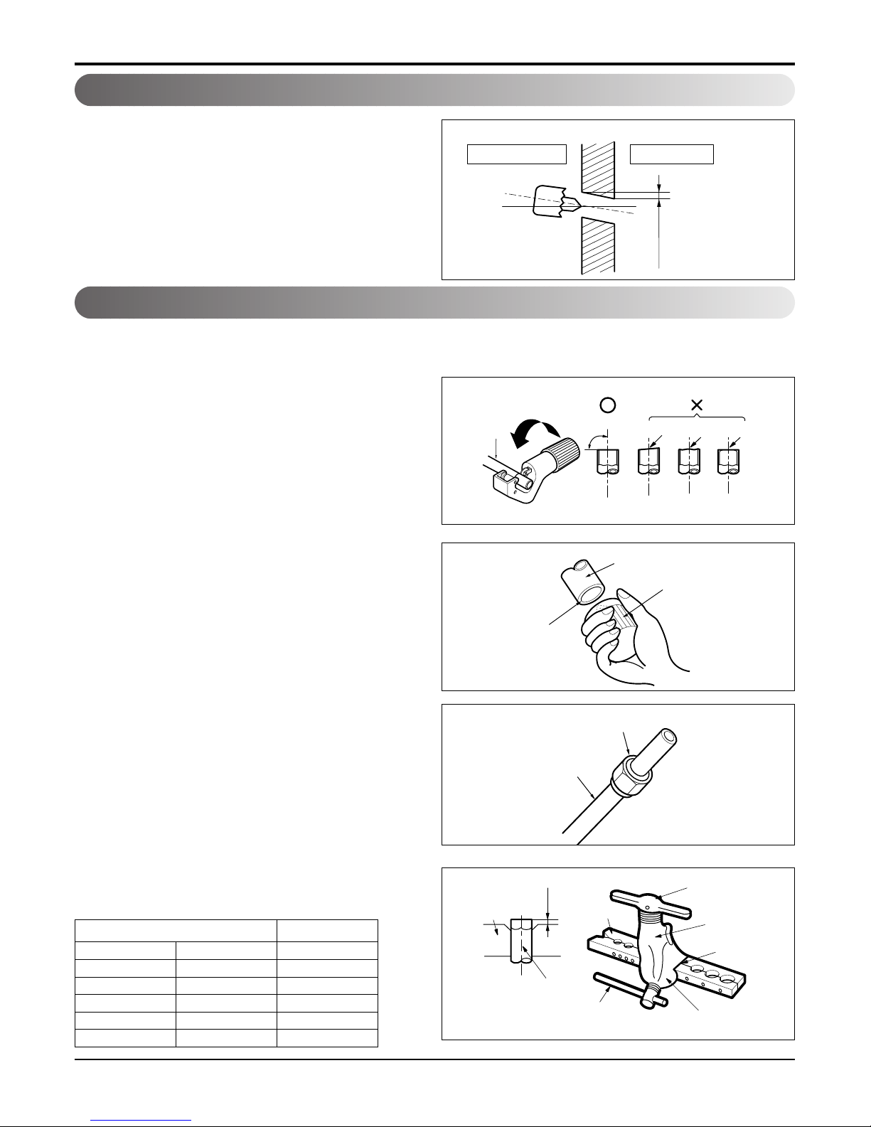
• Drill the piping hole with a ø70mm hole core drill.
Drill the piping hole at either the right or the left with
the hole slightly slanted to the outdoor side.
Drill a Hole in the Wall
5-7mm
(3/16"~5/16")
Indoor
WALL
Outdoor
Flaring Work
Main cause for gas leakage is due to defect in flaring work. Carry out correct flaring work in the following procedure.
Cut the pipes and the cable.
1. Use the piping kit accessory or the pipes purchased
locally.
2. Measure the distance between the indoor and the outdoor unit.
3. Cut the pipes a little longer than measured distance.
4. Cut the cable 1.5m longer than the pipe length.
Burrs removal
1. Completely remove all burrs from the cut cross section
of pipe/tube.
2. Put the end of the copper tube/pipe in a downward
direction as you remove burrs in order to avoid dropping burrs into the tubing.
Putting nut on
• Remove flare nuts attached to indoor and outdoor unit,
then put them on pipe/tube having completed burr
removal.
(not possible to put them on after flaring work)
Flaring work
1. Firmly hold copper pipe in a die in the dimension shown
in the table below.
2. Carry out flaring work with the flaring tool.
Copper
pipe
90°
Slanted Uneven Rough
Pipe
Reamer
Point down
Flare nut
Copper tube
mm inch mm
Ø6.35 1/4 0~0.5
Ø9.52 3/8 0~0.5
Ø12.7 1/2 0~0.5
Ø15.88 5/8 0~1.0
Ø19.05 3/4 1.0~1.3
Outside diameter A
Bar
Copper pipe
Clamp handle
Red arrow mark
Cone
Yoke
Handle
Bar
"A"
- 16 -
Copyright ©2009 LG Electronics. Inc. All right reserved.
Only for training and service purposes
LGE Internal Use Only
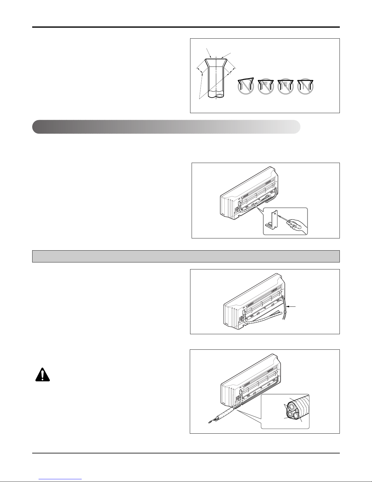
Installation
Check
1. Compare the flared work with the figure by.
2. If a flared section is defective, cut it off and do flaring
work again.
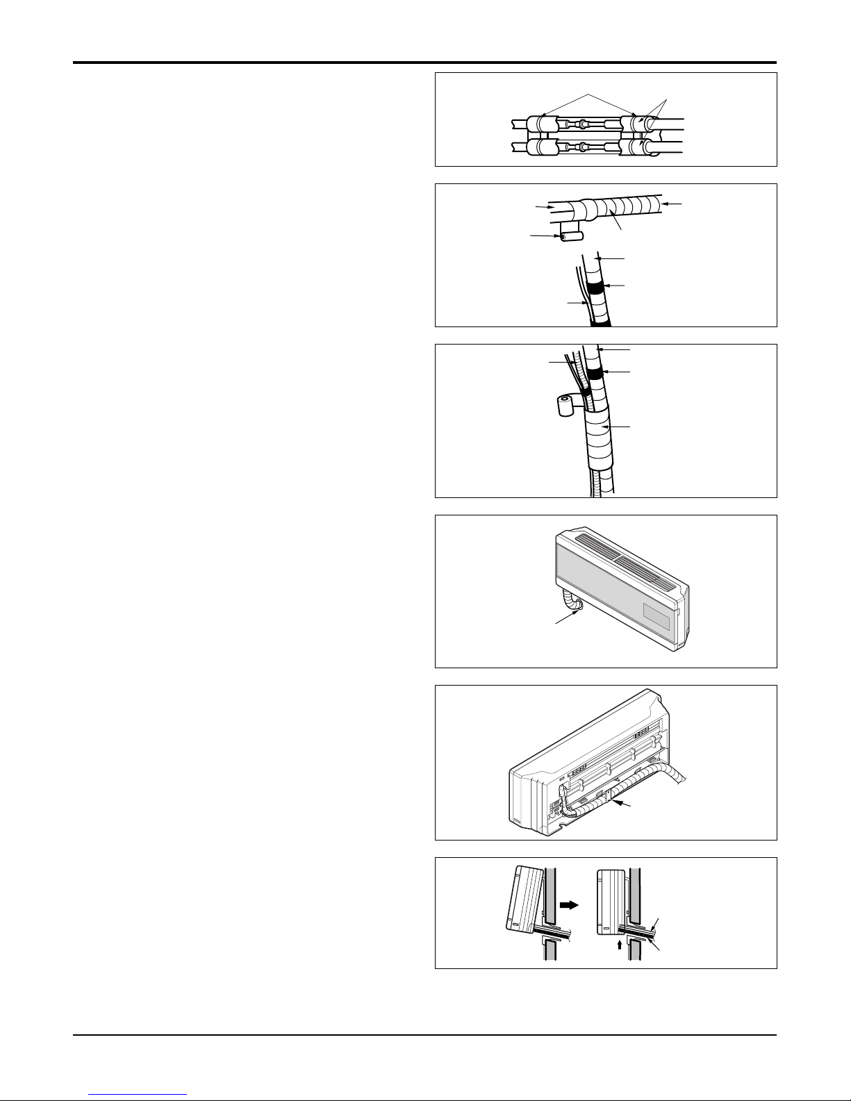
Indoor
1. Prepare the indoor unit's piping and drain hose for installation through the wall.
2. Remove the plastic tubing retainer(see the illustration
by) and pull the tubing and drain hose away from
chassis.
3. Replace the plastic tubing holder in the original position.(Optional)
1. Route the indoor tubing and the drain hose in the
direction of rear right.
2.
Insert the connecting cable into the indoor unit from the
outdoor unit through the piping hole.
• Do not connect the cable to the indoor unit.
• Make a small loop with the cable for easy connection later.
3. Tape the tubing, drain hose, and the connecting
cable. Be sure that the drain hose is located at the
lowest side of the bundle. Locating at the uper side
can cause drain pan to overflow inside the unit.
CAUTION: If the drain hose is routed inside
the room, insulate the hose with an insulation
material* so that dripping from
"sweating"(condensation) will not damage furniture or floors.
*Foamed polyethylene or equivalent is recommended.
Inclined
Inside is shiny without scratches
Smooth all round
Even length
all round
Surface
damaged
Cracked Uneven
thickness
= Improper flaring =
Connecting the Piping
For right rear piping
Drain hose
Connecting
pipe
Connecting cable
Tape
Drain hose
- 17 -
Copyright ©2009 LG Electronics. Inc. All right reserved.
Only for training and service purposes
LGE Internal Use Only
Installation
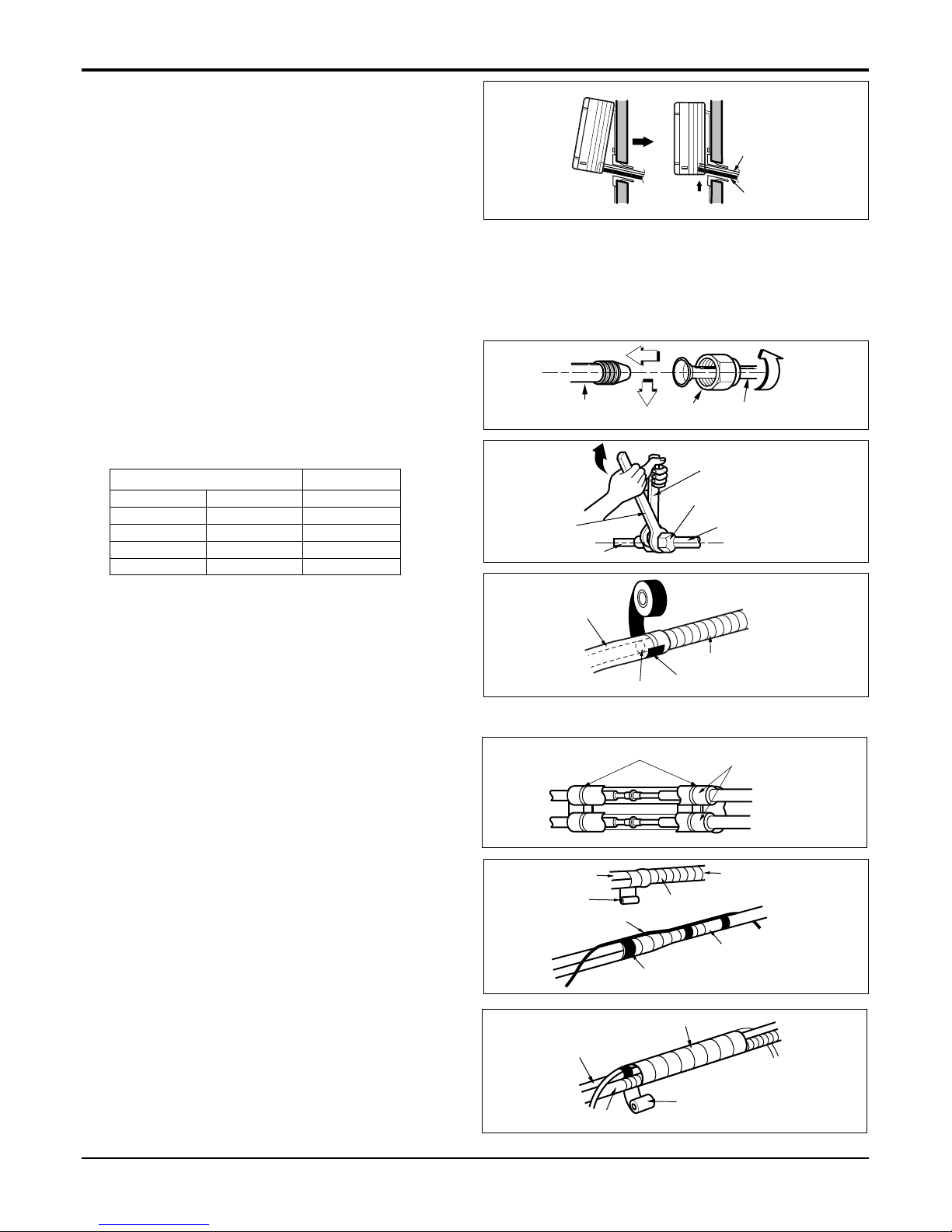
4. Indoor unit installation
Hook the indoor unit onto the upper portion of the
installation plate.(Engage the two hooks of the rear
top of the indoor unit with the upper edge of the
installation plate.) Ensure that the hooks are properly
seated on the installation plate by moving it left and
right.
Press the lower left and right sides of the unit against
the installation plate until the hooks engage into their
slots(clicking sound).
Connecting the piping to the indoor unit and drain
hose to drain pipe.
1. Align the center of the pipes and sufficiently tighten
the flare nut by hand.
2. Tighten the flare nut with a wrench.
3. When extending the drain hose at the indoor unit,
install the drain pipe.
Wrap the insulation material around the connecting
portion.
1. Overlap the connection pipe insulation material and
the indoor unit pipe insulation material. Bind them
together with vinyl tape so that there may be no gap.
2. Wrap the area which accommodates the rear piping
housing section with vinyl tape.
3. Bundle the piping and drain hose together by wrap-
ping them with vinyl tape for enough to cover where
they fit into the rear piping housing section.
Drain hose
Connecting
cable
Indoor unit tubing Flare nut Pipes
Wrench
Indoor unit tubing
Open-end wrench (fixed)
Connection pipe
Flare nut
mm inch kg.m
Ø6.35 1/4 1.8
Ø9.52 3/8 4.2
Ø12.7 1/2 5.5
Ø15.88 5/8 6.6
Outside diameter Torque
Vinyl tape(narrow)
Adhesive
Drain pipe
Indoor unit drain hose
Plastic bands
Insulation material
Wrap with vinyl tape
Drain hose
Pipe
Vinyl tape(wide)
Vinyl tape(narrow)
Connection pipe
Connecting cable
Vinyl tape (wide)
Wrap with vinyl tape
Indoor unit pipe
Pipe
- 18 -
Copyright ©2009 LG Electronics. Inc. All right reserved.
Only for training and service purposes
LGE Internal Use Only
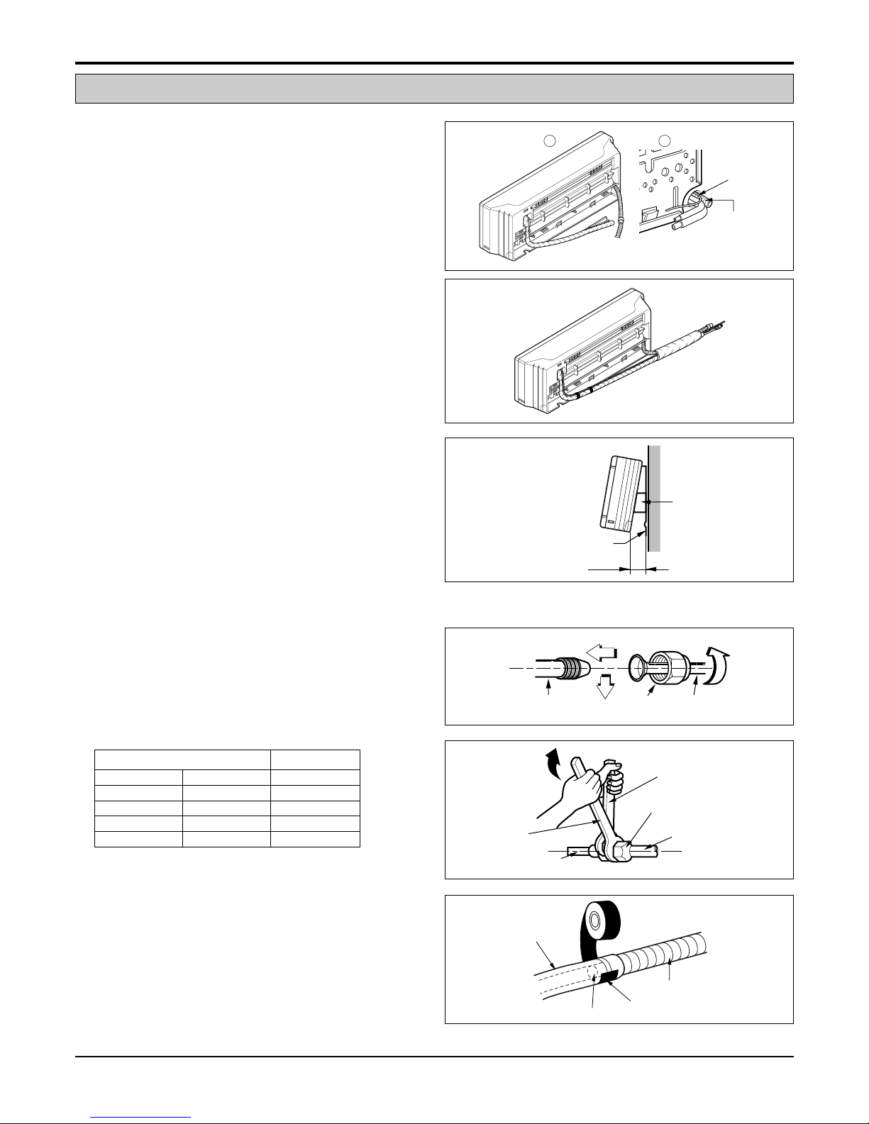
Installation
1. Route the indoor tubing and the drain hose to the
required piping hole position.
2. Insert the piping, drain hose, and the connecting
cable into the piping hole.
3.
Insert the connecting cable into the indoor unit.
• Don't connect the cable to the indoor unit.
• Make a small loop with the cable for easy connec-
tion later.
4. Tape the drain hose and the connecting cables.
5. Indoor unit installation
• Hang the indoor unit from the hooks at the top of the
installation plate.
• Insert the spacer etc. between the indoor unit and
the installation plate and separate the bottom of the
indoor unit from the wall.
Connecting the piping to the indoor unit and the
drain hose to drain pipe.
1. Align the center of the pipes and sufficiently tighten
the flare nut by hand.
2. Tighten the flare nut with a wrench.
3. When extending the drain hose at the indoor unit,
install the drain pipe.
For left rear piping
Drain pipe
Connecting
cable
1 2
Installation plate
Spacer
Indoor unit
8cm
Indoor unit tubing Flare nut Pipes
Wrench
Indoor unit tubing
Connection pipe
Flare nut
Open-end wrench (fixed)
Vinyl tape
Adhesive
Drain hose
Indoor unit drain hose
(narrow)
mm inch kg.m
Ø6.35 1/4 1.8
Ø9.52 3/8 4.2
Ø12.7 1/2 5.5
Ø15.88 5/8 6.6
Outside diameter Torque
- 19 -
Copyright ©2009 LG Electronics. Inc. All right reserved.
Only for training and service purposes
LGE Internal Use Only
Installation
Wrap the insulation material around the connecting
portion.
1. Overlap the connection pipe heat insulation and the
indoor unit pipe heat insulation material. Bind them
together with vinyl tape so that there may be no gap.
2. Wrap the area which accommodates the rear piping
housing section with vinyl tape.
3. Bundle the piping and drain hose together by wrapping them with cloth tape over the range within which
they fit into the rear piping housing section.
Reroute the pipings and the drain hose across the
back of the chassis.
Set the pipings and the drain hose to the back of
the chassis with the tubing holder.
• Hook the edge of tubing holder to tap on chassis and
push the bottom of tubing holder to be engaged at the
bottom of chassis.
Indoor unit installation
1. Remove the spacer.
2. Ensure that the hooks are properly seated on the
installation plate by moving it left and right.
3. Press the lower left and right sides of the unit against
the installation plate until the hooks engage into their
slots(clicking sound).
Plastic bands
Insulation material
Vinyl tape(narrow)
Connection
pipe
Connecting cable
Indoor
unit piping
Pipe
Vinyl tape
(wide)
Wrap with vinyl tape
Drain hose
Vinyl tape(narrow)
Pipe
Wrap with
vinyl tape(wide)
Piping for
passage through
piping hole
Drain hose
Connecting
cable
Tubing holder
- 20 -
Copyright ©2009 LG Electronics. Inc. All right reserved.
Only for training and service purposes
LGE Internal Use Only
Installation
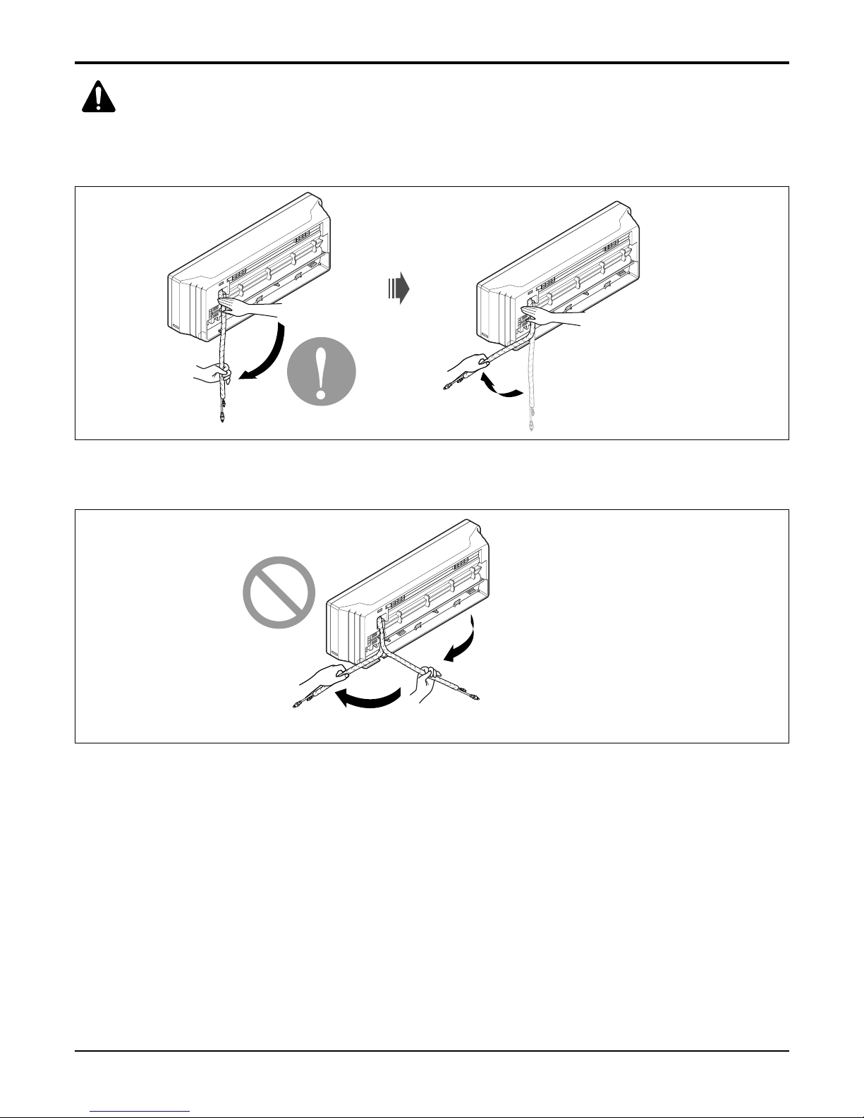
CAUTION: Installation Information
For left piping. Follow the instruction below.
Good case
• Press on the upper side of clamp and unfold the tubing to downward slowly.
Bad case
• Following bending type from right to left may cause damage to the tubing.
- 21 -
Copyright ©2009 LG Electronics. Inc. All right reserved.
Only for training and service purposes
LGE Internal Use Only
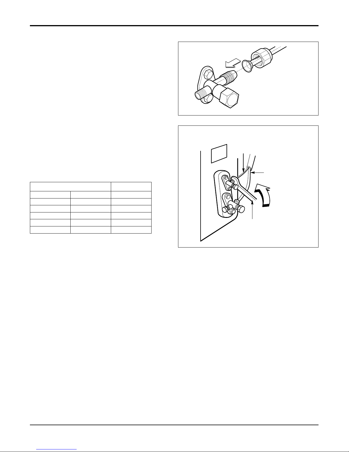
Installation
Outdoor
Align the center of the pipings and sufficiently tighten
the flare nut by hand.
Finally, tighten the flare nut with torque wrench until the
wrench clicks.
• When tightening the flare nut with torque wrench,
ensure the direction for tightening follows the arrow on
the wrench.
mm inch kg.m
Ø6.35 1/4 1.8
Ø9.52 3/8 4.2
Ø12.7 1/2 5.5
Ø15.88 5/8 6.6
Ø19.05 3/4 6.6
Outside diameter Torque
Outdoor unit
Liquid side piping
(Smaller diameter)
Gas side
piping
(Bigger
diameter)
Torque wrench
- 22 -
Copyright ©2009 LG Electronics. Inc. All right reserved.
Only for training and service purposes
LGE Internal Use Only
Installation
Indoor
Connect the cable to the indoor unit by connecting the wires to the terminals on the control board individually
according to the outdoor unit connection. (Ensure that the color of the wires of the outdoor unit and the terminal No.
are the same as those of the indoor unit.)
Connecting the Cables
CAUTION:
• The above circuit diagram is subject to change without notice.
• The earth wire should be longer than the common wires.
• When installing, refer to the circuit diagram behind the panel front of the indoor unit.
• Connect the wires firmly so that they may not be pulled out easily.
• Connect the wires according to color codes, referring to the wiring diagram.
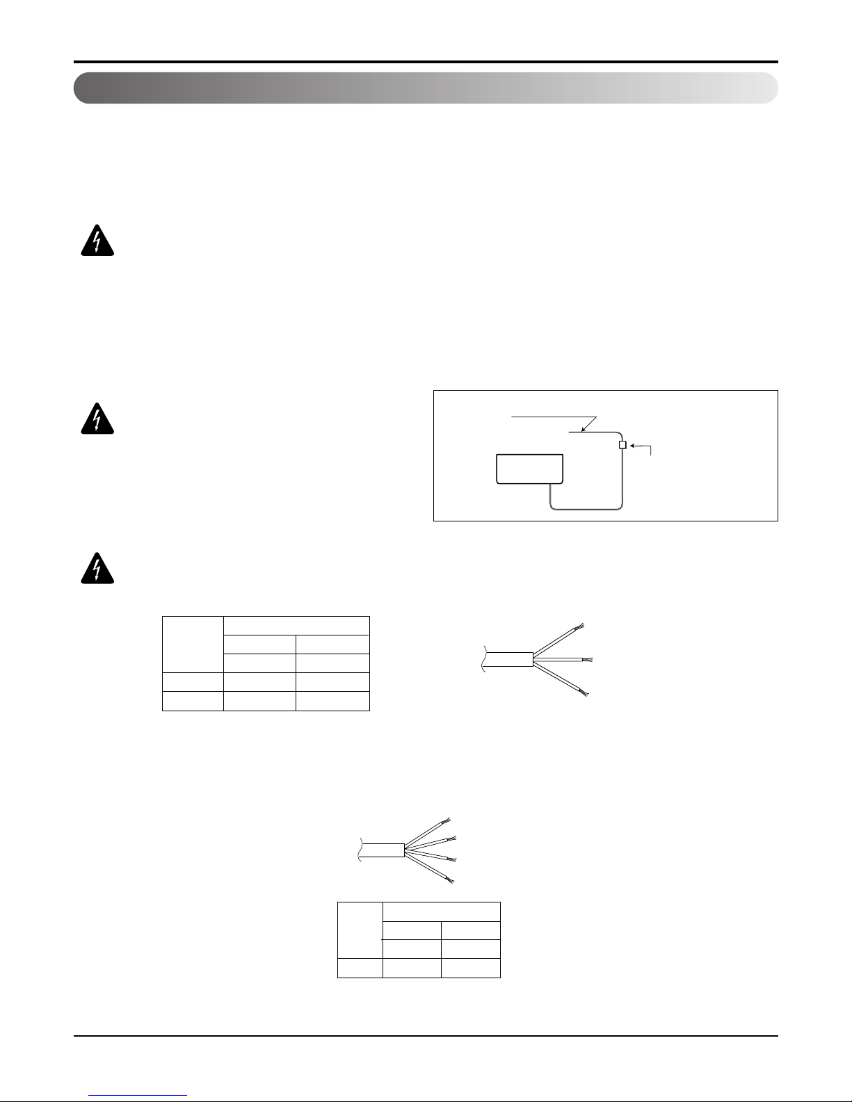
CAUTION: If a power plug is not
used, provide a circuit breaker
between power source and the unit
as shown by.
CAUTION:
The power cord connected to the "A" unit should be selected according to
the following specifications(Type "B" approved by HAR or SAA).
The power connecting cable connecting the indoor and outdoor unit should be selected
according to the following specifications (Type "B" approved by HAR or SAA).
Air
Conditioner
Main power source
Circuit Breaker
Use a circuit breake
or time delay fuse.
18k 24k
2.5 2.5
Unit(A) Indoor Indoor
Cable Type(B)
H05VV-F H05VV-F
NORMAL CROSS
-SECTIONAL AREA
Grade
(mm2)
18k 24k
2.5 2.5
Cable Type(B)
H07RN-F H07RN-F
NORMAL
CROSS
-SECTIONAL
AREA
Grade
(mm2)
- 23 -
Copyright ©2009 LG Electronics. Inc. All right reserved.
Only for training and service purposes
LGE Internal Use Only
Installation
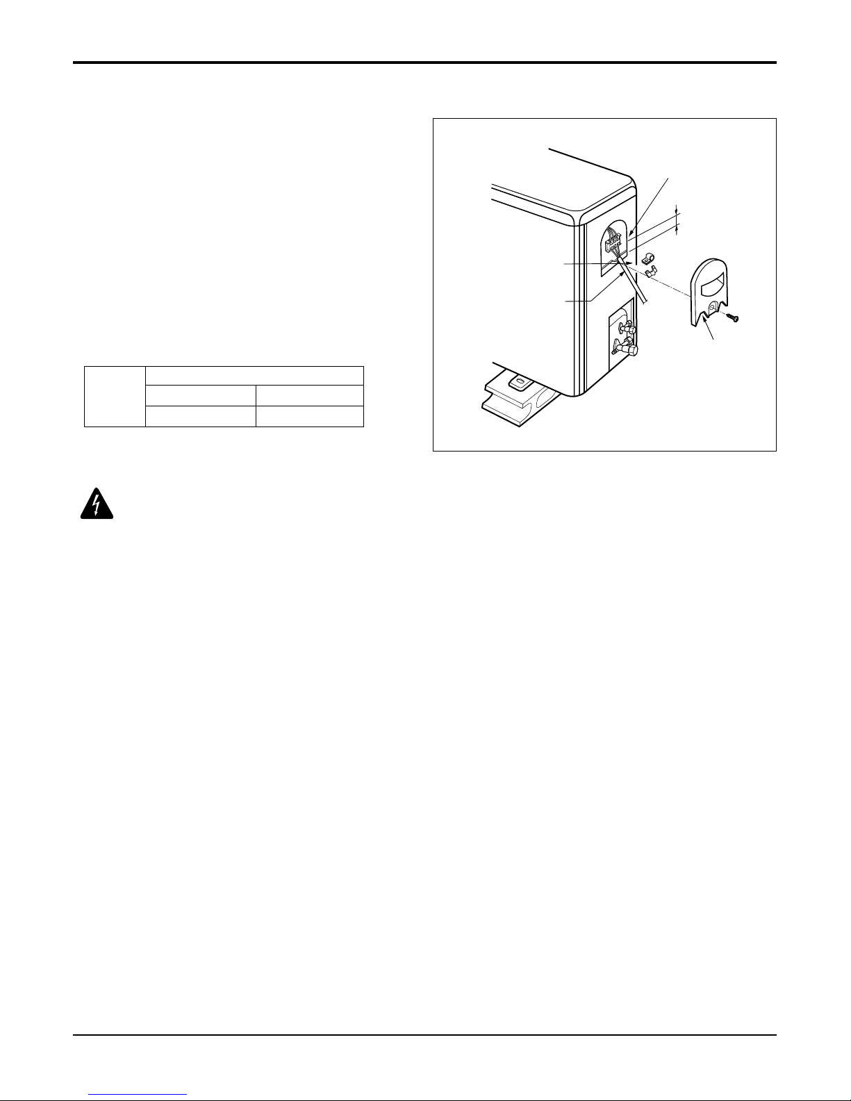
Outdoor
1. Remove the control cover from the unit by loosening
the screw.
Connect the wires to the terminals on the control
board individually.
2. Secure the cable onto the control board with the cord
clamp.
3. Refix the control cover to the original position with the
screw.
4. Use a recognized circuit breaker 20A(12k) between
the power source and the unit.
A disconnecting device to adequately disconnect all
supply lines must be fitted.
Terminal block
Over 5mm
Cover control
Connecting cable
Connecting cable
Outdoor Unit
18k
20
24k
30
Circuit
Breaker
(A)
Grade
CAUTION: According to the confirmation of the above conditions, prepare the
wiring as follows.
1. Never fail to have an individual power circuit specifically for the air conditioner. As for the method of
wiring, be guided by the circuit diagram posted on the inside of control cover.
2. The screw which fasten the wiring in the casing of electrical fittings are liable to come loose from
vibrations to which the unit is subjected during the course of transportation. Check them and make
sure that they are all tightly fastened. (If they are loose, it could cause burn-out of the wires.)
3. Specification of power source.
4. Confirm that electrical capacity is sufficient.
5. See to that the starting voltage is maintained at more than 90 percent of the rated voltage marked on
the name plate.
6. Confirm that the cable thickness is as specified in the power source specification.
(Particularly note the relation between cable length and thickness.
7. Always install an earth leakage circuit breaker in a wet or moist area.
8. The following would be caused by voltage drop.
• Vibration of a magnetic switch, which will damage the contact point, fuse breaking, disturbance of the normal function
of the overload.
9. The means for disconnection from a power supply shall be incorporated in the fixed wiring and have
an air gap contact separation of at least 3mm in each active(p
hase) conductors.
- 24 -
Copyright ©2009 LG Electronics. Inc. All right reserved.
Only for training and service purposes
LGE Internal Use Only
Installation
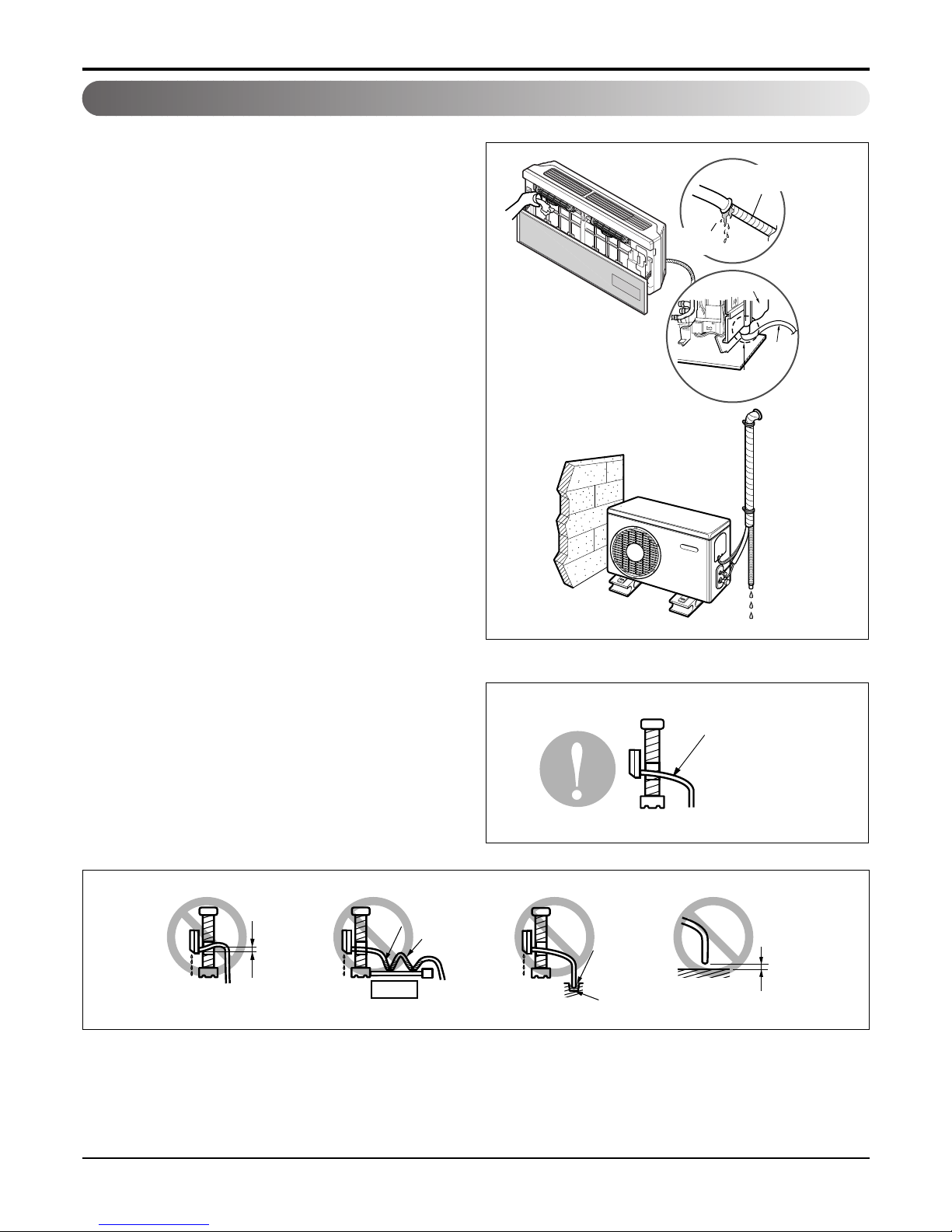
Checking the Drainage
To check the drainage.
1. Pour a glass of water on the evaporator.
2. Ensure the water flows through the drain hose of the
indoor unit without any leakage and goes out the
drain exit.
Drain piping
1. The drain hose should point downward for easy drain
flow.
2. Do not make drain piping like the following.
Drain pan
Drain
hose
Leakage
checking
Connecting area
drain hose
Leakage
checking
Downward slope
Do not raise
Accumulated
drain water
Tip of drain hose
dipped in water
Air
Waving
Water
leakage
Water
leakage
Ditch
Less than
50mm gap
Water
leakage
- 25 -
Copyright ©2009 LG Electronics. Inc. All right reserved.
Only for training and service purposes
LGE Internal Use Only
Installation
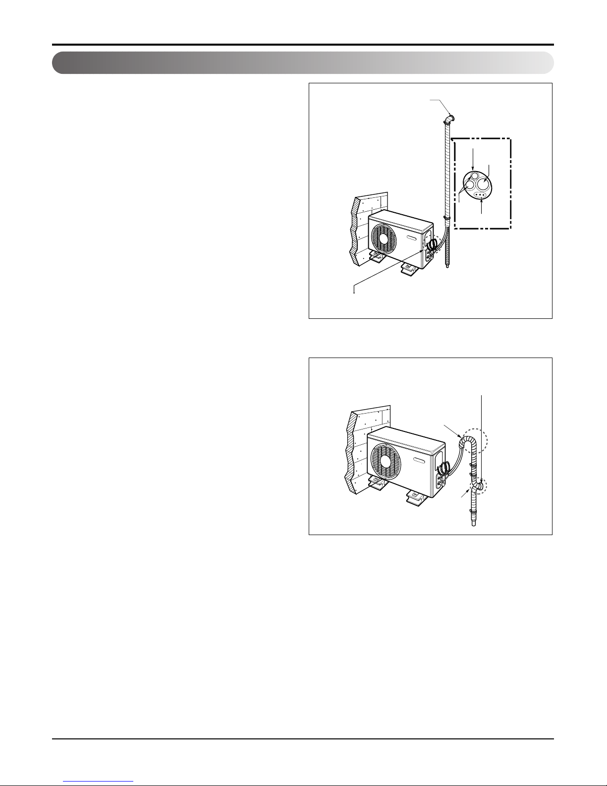
Forming the Piping
Form the piping by wrapping the connecting portion of the indoor unit with insulation material and secure it with two kinds
of vinyl tapes.
• If you want to connect an additional drain hose, the
end of the drain outlet should be routed above the
ground. Secure the drain hose appropriately.
In cases where the outdoor unit is
installed below the indoor unit perform the
following.
1. Tape the piping, drain hose and connecting cable
from down to up.
2. Secure the tapped piping along the exterior wall
using saddle or equivalent.
In cases where the Outdoor unit is
installed above the Indoor unit perform the
following.
1. Tape the piping and connecting cable from down to
up.
2. Secure the taped piping along the exterior wall. Form
a trap to prevent water entering the room.
3. Fix the piping onto the wall by saddle or equivalent.
Taping
Drain hose
Pipings
Connecting cable
Trap is required to prevent water
from entering into electrical parts.
Seal small openings
around pipings with a
gum type sealer.
Seal a small opening
around the pipings
with gum type sealer.
Trap
Trap
 Loading...