

Lg Arub076dt2, Arub096dt2, Arub115dt2, Arub134dt2, Arun048gs2 Installation Guide
...
System
Heat Recovery Outdoor Unit
INSTALLATION MANUAL
LG
MODELS: ARUB Series
website http://www.lgservice.com
IMPORTANT
• Please read this installation manual completely before
installing the product.
• Installation work must be performed in accordance with
the national wiring standards by authorized personnel
only.
• Please retain this installation manual for future reference
after reading it thoroughly.
R410A
ENGLISH FRANÇAIS ESPAÑOL
2 Outdoor Unit
CAUTION
: Improper installation, adjustment, alteration, service or maintenance can void the warranty.
The weight of the condensing unit requires caution and proper handling procedures when lifting
or moving to avoid personal injury. Use care to avoid contact with sharp or pointed edges.
Safety Precautions
• Always wear safety eye wear and work gloves when installing equipment.
• Never assume electrical power is disconnected. Check with meter and equipment.
• Keep hands out of fan areas when power is connected to equipment.
• R-410A causes frostbite burns.
• R-410A is toxic when burned.
NOTE TO INSTALLING DEALER: The Owners Instructions and Warranty are to be given to the owner
or prominently displayed near the indoor Furnace/Air Handler Unit.
When wiring:
Electrical shock can cause severe personal injury or death. Only a qualified,
experienced electrician should attempt to wire this system.
• Do not supply power to the unit until all wiring and tubing are completed or reconnected and checked.
• Highly dangerous electrical voltages are used in this system. Carefully refer to the wiring diagram and these
instructions when wiring. Improper connections and inadequate grounding can cause accidental injury or death.
• Ground the unit following local electrical codes.
• Connect all wiring tightly. Loose wiring may cause overheating at connection points and a possible fire hazard.
When transporting:
Be careful when picking up and moving the indoor and outdoor units. Get a partner to help, and
bend your knees when lifting to reduce strain on your back. Sharp edges or thin aluminum fins on
the air conditioner can cut your finger.
When installing...
... in a wall: Make sure the wall is strong enough to hold the unit's weight.
It may be necessary to construct a strong wood or metal frame to provide added support.
... in a room: Properly insulate any tubing run inside a room to prevent "sweating" that can cause
dripping and water damage to wall and floors.
... in moist or uneven locatinons: Use a raised concrete pad or concrete blocks provide a solid,
level foundation for the outdoor unit. This prevents water damage and abnormal vibration.
... in an area with high winds: Securely anchor the outdoor unit down with bolts and a metal
frame. Provide a suitable air baffle.
... in a snowy area(for Heat Pump Model): Install the outdoor unit on a raised platform that is
higher than drifting snow. Provide snow vents.
When connecting refrigerant tubing
• Keep all tubing runs as short as possible.
• Use the flare method for connecting tubing.
• Check carefully for leaks before starting the test run.
When servicing
• Turn the power OFF at the main power box(mains) before opening the unit to check or repair
electrical parts and wiring.
• Keep your fingers and clothing away from any moving parts.
• Clean up the site after you finish, remembering to check that no metal scraps or bits of wiring have
been left inside the unit being serviced.
Special warnings
WARNING
• Installation or repairs made by unqualified persons can result in hazards to you and others.
Installation MUST conform with local building codes or, in the absence of local codes, with the National Electrical
Code NFPA 70/ANSI C1-1993 or current edition and Canadian Electrical Code Part1 CSA C.22.1.
• The information contained in the manual is intended for use by a qualified service technician familiar with safety
procedures and equipped with the proper tools and test instruments.
• Failure to carefully read and follow all instructions in this manual can result in equipment malfunction, property
damage, personal injury and/or death.
IMPORTANT!
Please read this instruction sheet completely before installing the product.
This air conditioning system meets strict safety and operating standards. As the installer or service
person,it is an important part of your job to install or service the system so it operates safely and
efficiently.

Installation Manual 3
ENGLISH
ARUB Series Outdoor Unit Installation Manual
TABLE OF CONTENTS
Safety Precautions................................................................................................................4
Installation Process..............................................................................................................8
Outdoor Unit Information.....................................................................................................9
Environment-friendly Alternative Refrigerant R410A......................................................13
Select the Best Location....................................................................................................13
Installation Space ...............................................................................................................15
Lifting method.....................................................................................................................19
Installation...........................................................................................................................20
Refrigerant piping installation...........................................................................................22
Electrical Wiring..................................................................................................................41
HR unit PCB ........................................................................................................................54
Main PCB.............................................................................................................................65
Test Run...............................................................................................................................72
Caution For Refrigerant Leak ............................................................................................89
Installation guide at the seaside .......................................................................................91
4 Outdoor Unit
Safety Precautions
Safety Precautions
To prevent injury to the user or other people and property damage, the following instructions must
be followed.
■ Incorrect operation due to ignoring instruction will cause harm or damage. The seriousness is
classified by the following indications.
■ Meanings of symbols used in this manual are as shown below.
This symbol indicates the possibility of death or serious injury.
This symbol indicates the possibility of injury or damage to properties only.
Be sure not to do.
Be sure to follow the instruction.
■ Installation
Have all electric work done by a licensed
electrician according to "Electric Facility
Engineering Standard" and "Interior Wire
Regulations" and the instructions given in
this manual and always use a special circuit.
• If the power source capacity is inadequate or
electric work is performed improperly, electric
shock or fire may result.
Ask the dealer or an authorized technician to
install the air conditioner.
• Improper installation by the user may result in
water leakage, electric shock, or fire.
Always ground the product.
• There is risk of fire or electric shock.
Always intstall a dedicated circuit and breaker.
• Improper wiring or installation may cause fire or
electric shock.
For re-installation of the installed product,
always contact a dealer or an Authorized
Service Center.
• There is risk of fire, electric shock, explosion, or
injury.
Do not install, remove, or re-install the unit
by yourself (customer).
• There is risk of fire, electric shock, explosion, or
injury.
Do not store or use flammable gas or
combustibles near the air conditioner.
• There is risk of fire or failure of product.
Use the correctly rated breaker or fuse.
• There is risk of fire or electric shock.
Prepare for strong wind or earthquake and
install the unit at the specified place.
• Improper installation may cause the unit to topple and result in injury.
Do not install the product on a defective
installation stand.
• It may cause injury, accident, or damage to the
product.
ENGLISH
Installation Manual 5
Safety Precautions
Ventilate before operating air conditioner
when gas leaked out.
• It may cause explosion, fire, and burn.
Securely install the cover of control box and
the panel.
• If the cover and panel are not installed securely,
dust or water may enter the outdoor unit and fire
or electric shock may result.
If the air conditioner is installed in a small room, measures must be taken to prevent the
refrigerant concentration from exceeding the safety limit when the refrigerant leaks.
• Consult the dealer regarding the appropriate measures to prevent the safety limit from being exceeded. Should the refrigerant leak and cause the safety limit to be exceeded, harzards due to lack of oxygen in the room could result.
■ Operation
Do not damage or use an unspecified power
cord.
• There is risk of fire, electric shock, explosion, or
injury.
Use a dedicated outlet for this appliance.
• There is risk of fire or electrical shock.
Be cautious that water could not enter the
product.
• There is risk of fire, electric shock, or product
damage.
Do not touch the power switch with wet
hands.
• There is risk of fire, electric shock, explosion, or
injury.
When installing and moving the air conditioner to another site, do not charge it with a
different refrigerant from the refrigerant
specified on the unit.
• If a different refrigerant or air is mixed with the
original refrigerant, the refrigerant cycle may
malfunction and the unit may be damaged.
Do not reconstruct to change the settings of
the protection devices.
• If the pressure switch, thermal switch, or other
protection device is shorted and operated
forcibly, or parts other than those specified by
LGE are used, fire or explosion may result.
When the product is soaked (flooded or
submerged), contact an Authorized Service
Center.
• There is risk of fire or electric shock.
Be cautious not to touch the sharp edges
when installing.
• It may cause injury.
T ake care to ensure that nobody could step
on or fall onto the outdoor unit.
• This could result in personal injury and product
damage.
Do not open the inlet grille of the product
during operation. (Do not touch the electrostatic filter, if the unit is so equipped.)
• There is risk of physical injury, electric shock, or
product failure.
■ Installation
Always check for gas (refrigerant) leakage
after installation or repair of product.
• Low refrigerant levels may cause failure of
product.
Do not install the product where the noise or
hot air from the outdoor unit could damage
the neighborhoods.
• It may cause a problem for your neighbors.

6 Outdoor Unit
Safety Precautions
Keep level even when installing the product.
• To avoid vibration or water leakage.
Do not install the unit where combustible gas
may leak.
• If the gas leaks and accumulates around the
unit, an explosion may result.
Use power cables of sufficient current
carrying capacity and rating.
• Cables that are too small may leak, generate
heat, and cause a fire.
Do not use the product for special purposes,
such as preserving foods, works of art, etc. It
is a consumer air conditioner, not a precision
refrigeration system.
• There is risk of damage or loss of property.
Keep the unit away from children. The heat
exchanger is very sharp.
• It can cause the injury, such as cutting the finger.
Also the damaged fin may result in degradation
of capacity.
When installting the unit in a hospital, communication station, or similar place, provide
sufficient protection against noise.
•
The inverter equipment, private power generator,
high-frequency medical equipment, or radio communication equipment may cause the air conditioner to operate erroneously, or fail to operate. On the
other hand, the air conditioner may affect such
equipment by creating noise that disturbs medical
treatment or image broadcasting.
Do not install the product where it is exposed to sea wind (salt spray) directly.
• It may cause corrosion on the product. Corrosion, particularly on the condenser and evaporator fins,
could cause product malfunction or inefficient operation.
■ Operation
Do not use the air conditioner in special
environments.
• Oil, steam, sulfuric smoke, etc. can significantly
reduce the performance of the air conditioner or
damage its parts.
Do not block the inlet or outlet.
• It may cause failure of appliance or accident.
Make the connections securely so that the
outside force of the cable may not be applied
to the terminals.
• Inadequate connection and fastening may generate heat and cause a fire.
Be sure the installation area does not deteriorate with age.
• If the base collapses, the air conditioner could
fall with it, causing property damage, product
failure, or personal injury.
Install and insulate the drain hose to ensure that water is drained away properly based on the
installation manual.
• A bad connection may cause water leakage.

ENGLISH
Installation Manual 7
Safety Precautions
Safely dispose of the packing materials.
•
Packing materials, such as nails and other metal or
wooden parts, may cause stabs or other injuries.
•
Tear apart and throw away plastic packaging bags
so that children may not play with them. If children
play with a plastic bag which was not torn apart,
they face the risk of suffocation.
Turn on the power at least 6 hours before
starting operation.
• Starting operation immediately after turning on
the main power switch can result in severe
damage to internal parts. Keep the power switch
turned on during the operational season.
Be very careful about product transportation.
• Only one person should not carry the product if it weighs more than 20 kg.
• Some products use PP bands for packaging. Do not use any PP bands for a means of transportation.
It is dangerous.
• Do not touch the heat exchanger fins. Doing so may cut your fingers.
• When transporting the outdoor unit, suspending it at the specified positions on the unit base. Also
support the outdoor unit at four points so that it cannot slip sideways.
Do not touch any of the refrigerant piping
during and after operation.
• It can cause a burn or frostbite.
Do not operate the air conditioner with the
panels or guards removed.
• Rotating, hot, or high-voltage parts can cause
injuries.
Do not directly turn off the main power
switch after stopping operation.
• Wait at least 5 minutes before turning off the
main power switch. Otherwise it may result in
water leakage or other problems.
Auto-addressing should be done in condition of
connecting the power of all indoor and outdoour
units. Auto-addressing should also be done in
case of changing the indoor unit PCB.
Use a firm stool or ladder when cleaning or
maintaining the air conditioner.
• Be careful and avoid personal injury.
Do not insert hands or other objects through
the air inlet or outlet while the air conditioner
is plugged in.
• There are sharp and moving parts that could
cause personal injury.
8 Outdoor Unit
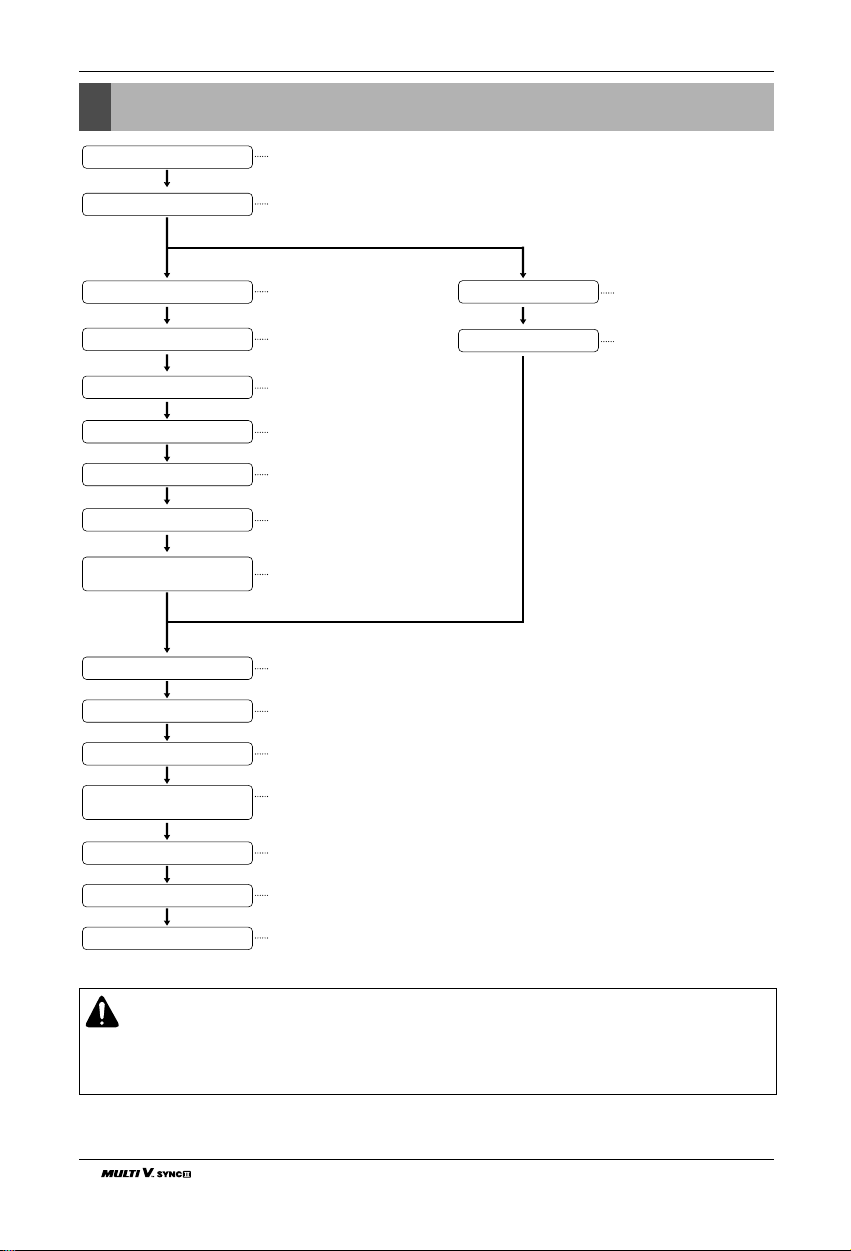
Installation Process
Installation Process
The foundation must be level
Outdoor unit foundation work
Avoid short circuits and ensure
sufficient space is allowed
for service
Installation of outdoor unit
In the final check for 24hours at 3.80 MPa(38.7 kgf/cm2) there must be no drop in pressure.
Airtight Test
Multiple core cable must not be used.
(suitable cable shouldbe selected)
Electrical work
(connection circuits and drive circuits)
Make sure no gaps are left where
the insulating materials are joined
Heat insulation work
Make sure airflow is sufficient
Duct work
Adjust to downward gradient
Drain pipe work
Special attention to dryness,
cleanness and tightness
Refrigerant piping work
Check model name to make
sure the fitting is made correctly
Installation of indoor unit and HR unit
Take account of gradient
of drain piping
Sleeve and insert work
Make relationship between outdoor, indoor, remote controller, and option connections clear.
(Prepare control circuit diagram)
Preparation of contract drawings
Indicate clearly who is to be responsible for switch settings
Determination of division work
The vacuum pump used must have a capacity of reaching at least 5 Torr, more than 1 hour.
Vacuum drying
Recharge correctly as calculated in this manual and record the amount of added refrigerant
Additional charge of refrigerant
Make sure there are no gaps left between the facing materials used on the ceiling
Fit facing panels
Refer to automatic addressing for Indoor units and pipe detection.
Preheat the crank case with the electrical heater for more than 6 hours.
(In case of the outdoor temperature below 10°C(50˚F))
Automatic addressing for Indoor
units and pipe detection
Run each indoor unit in turn to make sure the pipe work has been fitted correctly
Test run adjustment
Transfer to customer with explanation
Explain the proper use of the system as clearly as possible to your customer and make
sure all relevant documentations are in order.
CAUTION:
The above list indicates the order in which the individual work operations are normally carried out but
this order may be varied where local conditions warrants such change.
Make sure additional charge the refrigerant before automatic addressing of indoor and pipe searching.
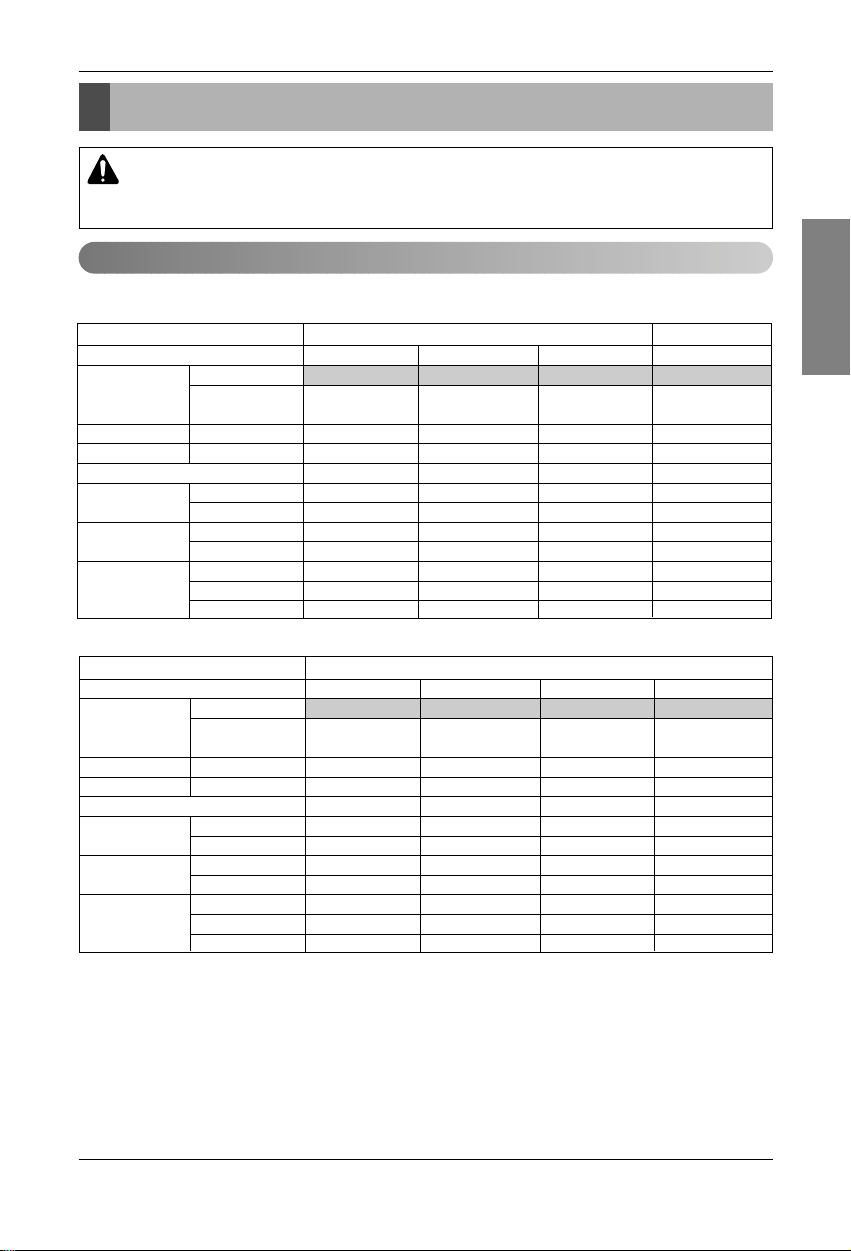
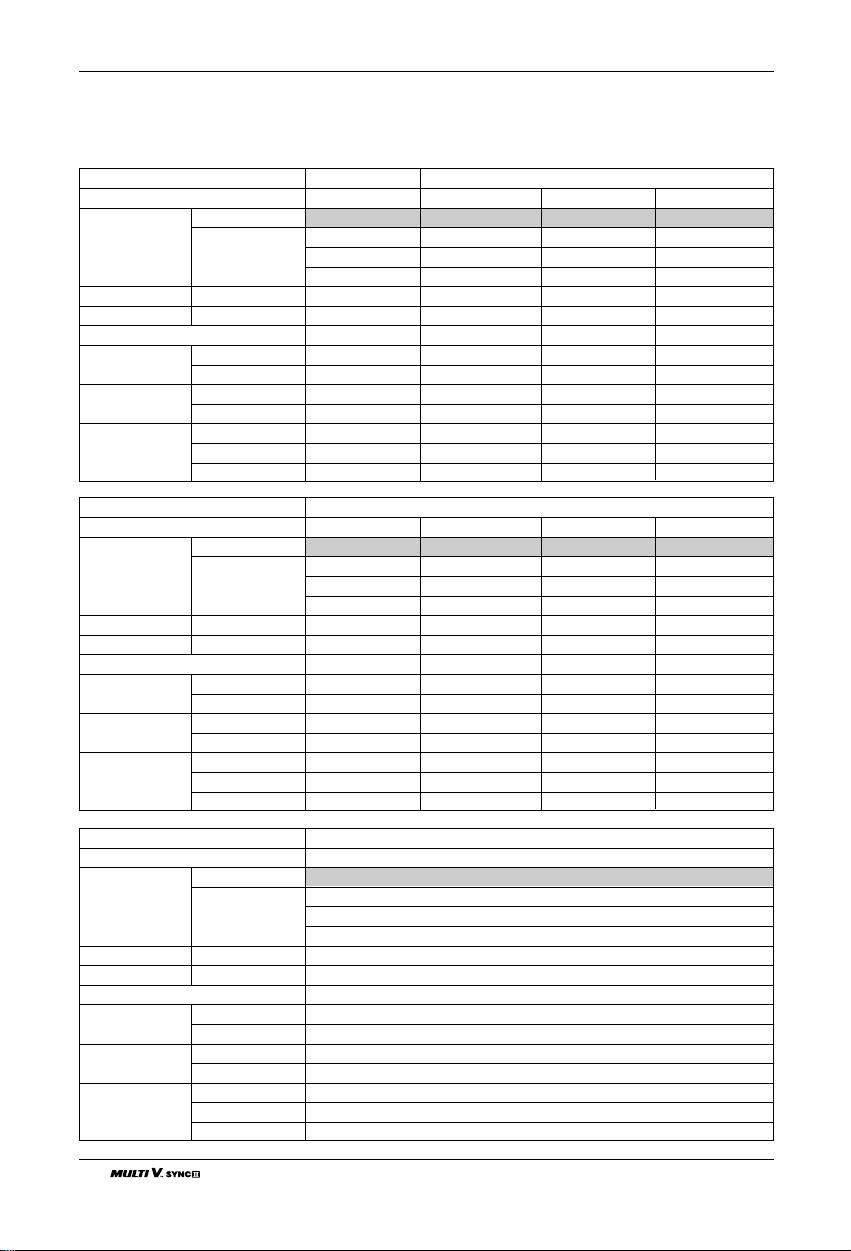
Outdoor Units Information
Outdoor Units Information
Power Supply: Outdoor Unit (3Ø, 208/230V, 60Hz)
CAUTION: Ratio of the connectable Indoor Units to the Outdoor: Within 50 ~ 130%
Ratio of the running Indoor Units to the Outdoor: Within 10 ~ 100%
A combination operation over 100% cause to reduce the total capacity.
■ Heat Recovery
Unit
Model(HP(Ton))
Model Combination Unit
Independent Unit
Product Charge kg(lbs)
CF(Correction Factor) kg(lbs)
Max. Connectable No. of Indoor Units
Net Weight kg
lbs
Dimensions mm
(WxHxD) inch
Connecting Pipes
Liquid Pipes[mm(
inch
)]
Low Pressure Pipes[mm(inch)]
High Pressure Gas Pipes[mm(inch)]
1 Outdoor Unit 2 Outdoor Units
8(6.5) 10(8.0) 12(9.5) 16(12.5)
ARUB076BT2 ARUB096BT2 ARUB115BT2 ARUB154BT2
ARUB076BT2
ARUB076BT2
8(17.6) 8(17.6) 8(17.6) 8+8(17.6+17.6)
-1(-2.2) 0(0) 1(2.2) -2(-4.4)
13 16 19 26
285 285 285 285+285
628 628 628 628+628
1,280x1,607x730 1,280x1,607x730 1,280x1,607x730
(1,280x1,607x730)x2
50-3/8 x 63-5/16 x 28-11/16 50-3/8 x 63-5/16 x 28-11/16 50-3/8 x 63-5/16 x 28-11/16
(50-3/8 x 63-5/16 x 28-11/16)x2
9.52(3/8) 9.52(3/8) 12.7(1/2) 12.7(1/2)
19.05(3/4) 22.2(7/8) 28.58(1 1/8) 28.58(1 1/8)
15.88(5/8) 19.05(3/4) 19.05(3/4) 22.2(7/8)
Unit
Model(HP(Ton))
Model Combination Unit
Independent Unit
Product Charge kg(lbs)
CF(Correction Factor) kg(lbs)
Max. Connectable No. of Indoor Units
Net Weight kg
lbs
Dimensions mm
(WxHxD) inch
Connecting Pipes
Liquid Pipes[mm(
inch
)]
Low Pressure Pipes[mm(inch)]
High Pressure Gas Pipes[mm(inch)]
2 Outdoor Unit
18(14.5) 20(16.0) 22(17.5) 24(19.0)
ARUB173BT2 ARUB192BT2 ARUB211BT2 ARUB230BT2
ARUB096BT2 ARUB096BT2 ARUB115BT2 ARUB115BT2
ARUB076BT2 ARUB096BT2 ARUB096BT2 ARUB115BT2
8+8(17.6+17.6) 8+8(17.6+17.6) 8+8(17.6+17.6) 8+8(17.6+17.6)
-1(-2.2) 0(0) 1(2.2) 2(4.4)
29 32 35 39
285+285 285+285 285+285 285+285
628+628 628+628 628+628 628+628
(1,280x1,607x730)x2 (1,280x1,607x730)x2 (1,280x1,607x730)x2 (1,280x1,607x730)x2
(50-3/8 x 63-5/16 x 28-11/16)x2 (50-3/8 x 63-5/16 x 28-11/16)x2 (50-3/8 x 63-5/16 x 28-11/16)x2 (50-3/8 x 63-5/16 x 28-11/16)x2
15.88(5/8) 15.88(5/8) 15.88(5/8) 15.88(5/8)
28.58(1 1/8) 28.58(1 1/8) 34.9(1 3/8) 34.9(1 3/8)
22.2(7/8) 22.2(7/8) 28.58(1 1/8) 28.58(1 1/8)
ENGLISH
Installation Manual 9
10 Outdoor Unit
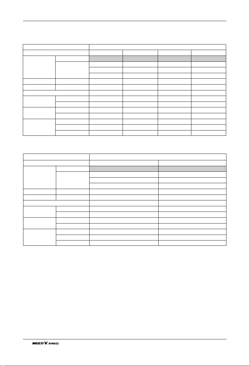
Outdoor Units Information
Unit
Model(HP(Ton))
Model Combination Unit
Independent Unit˜
Product Charge kg(lbs)
CF(Correction Factor) kg(lbs)
Max. Connectable No. of Indoor Units
Net Weight kg
lbs
Dimensions mm
(WxHxD) inch
Connecting Pipes
Liquid Pipes[mm(
inch
)]
Low Pressure Pipes[mm(inch)]
High Pressure Gas Pipes[mm(inch)]
3 Outdoor Units
26(20.5) 28(22.5) 30(24.0) 32(25.5)
ARUB250BT2 ARUB270BT2 ARUB290BT2 ARUB310BT2
ARUB096BT2 ARUB096BT2 ARUB096BT2 ARUB115BT2
ARUB076BT2 ARUB096BT2 ARUB096BT2 ARUB096BT2
ARUB076BT2 ARUB076BT2 ARUB096BT2 ARUB096BT2
8+8+8(17.6+17.6+17.6) 8+8+8(17.6+17.6+17.6) 8+8+8(17.6+17.6+17.6) 8+8+8(17.6+17.6+17.6)
-2(-4.4) -1(-2.2) 0(0) 1(2.2)
42 45 49 52
285+285+285 285+285+285 285+285+285 285+285+285
628+628+628 628+628+628 628+628+628 628+628+628
(1,280x1,607x730)x3 (1,280x1,607x730)x3 (1,280x1,607x730)x2 (1,280x1,607x730)x2
(50.4x63.3x28.7)x3 (50.4x63.3x28.7)x3 (50.4x63.3x28.7)x2 (50.4x63.3x28.7)x2
19.05(3/4) 19.05(3/4) 19.05(3/4) 19.05(3/4)
34.9(1 3/8) 34.9(1 3/8) 34.9(1 3/8) 34.9(1 3/8)
28.58(1 1/8) 28.58(1 1/8) 28.58(1 1/8) 28.58(1 1/8)
Unit
Model(HP(Ton))
Model Combination Unit
Independent Unit˜
Product Charge kg(lbs)
CF(Correction Factor) kg(lbs)
Max. Connectable No. of Indoor Units
Net Weight kg
lbs
Dimensions mm
(WxHxD) inch
Connecting Pipes
Liquid Pipes[mm(
inch
)]
Low Pressure Pipes[mm(inch)]
High Pressure Gas Pipes[mm(inch)]
3 Outdoor Units
34(27.0) 36(28.5)
ARUB330BT2 ARUB350BT2
ARUB115BT2 ARUB115BT2
ARUB115BT2 ARUB115BT2
ARUB096BT2 ARUB115BT2
8+8+8(17.6+17.6+17.6) 8+8+8(17.6+17.6+17.6)
2(4.4) 3(6.6)
55 58
285+285+285 285+285+285
628+628+628 628+628+628
(1,280x1,607x730)x2 (1,280x1,607x730)x2
(50.4x63.3x28.7)x2 (50.4x63.3x28.7)x2
19.05(3/4) 19.05(3/4)
34.9(1 3/8) 41.3(1 5/8)
28.58(1 1/8) 28.58(1 1/8)
ENGLISH
Installation Manual 11
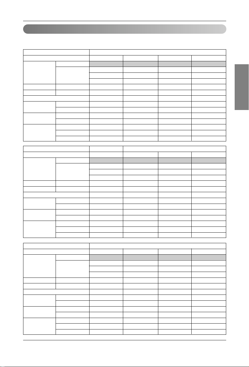
Outdoor Units Information
Power Supply: Outdoor Unit (3Ø, 460V, 60Hz)
■ Heat Recovery
Unit
Model(HP(Ton))
Model Combination Unit
Independent Unit˜
Product Charge kg(lbs)
CF(Correction Factor) kg(lbs)
Max. Connectable No. of Indoor Units
Net Weight kg
lbs
Dimensions mm
(WxHxD) inch
Connecting Pipes
Liquid Pipes[mm(
inch
)]
Low Pressure Pipes[mm(inch)]
High Pressure Gas Pipes[mm(inch)]
1 Outdoor Unit
8(6.5) 10(8.0) 12(9.5) 14(11.0)
ARUB076DT2 ARUB096DT2 ARUB115DT2 ARUB134DT2
ARUB076DT2 ARUB096DT2 ARUB115DT2 ARUB134DT2
8(17.6) 8(17.6) 8(17.6) 8(17.6)
-1(-2.2) 0(0) 1(2.2) 2(4.4)
13 16 20 23
240 285 285 285
529 628 628 628
1,280x1,607x730 1,280x1,607x730 1,280x1,607x730 1,280x1,607x730
50.4x63.3x28.7 50.4x63.3x28.7 50.4x63.3x28.7 50.4x63.3x28.7
9.52(3/8) 9.52(3/8) 12.7(1/2) 12.7(1/2)
19.05(3/4) 22.2(7/8) 28.58(1 1/8) 28.58(1 1/8)
15.88(5/8) 19.05(3/4) 19.05(3/4) 19.05(3/4)
Unit
Model(HP(Ton))
Model Combination Unit
Independent Unit
Product Charge kg(lbs)
CF(Correction Factor) kg(lbs)
Max. Connectable No. of Indoor Units
Net Weight kg
lbs
Dimensions mm
(WxHxD) inch
Connecting Pipes
Liquid Pipes[mm(
inch
)]
Low Pressure Pipes[mm(inch)]
High Pressure Gas Pipes[mm(inch)]
1 Outdoor Unit 2 Outdoor Units
16(12.5) 18(14.5 ) 20(16.0) 22(17.5)
ARUB154DT2 ARUB173DT2 ARUB192DT2 ARUB211DT2
ARUB154DT2 ARUB096DT2 ARUB115DT2 ARUB134DT2
ARUB076DT2 ARUB076DT2 ARUB076DT2
8(17.6) 8+8(17.6+17.6) 8+8(17.6+17.6) 8+8(17.6+17.6)
3(6.6) -1(-2.2) 0(0) 1(2.2)
26 29 32 35
285 285+240 285+240 285+240
628 628+529 628+529 628+529
1,280x1,607x730 (1,280x1,607x730)x2 (1,280x1,607x730)x2 (1,280x1,607x730)x2
50.4x63.3x28.7 (50.4x63.3x28.7)x2 (50.4x63.3x28.7)x2 (50.4x63.3x28.7)x2
12.7(1/2) 15.88(5/8) 15.88(5/8) 15.88(5/8)
28.58(1 1/8) 28.58(1 1/8) 28.58(1 1/8) 28.58(1 1/8)
22.2(7/8) 22.2(7/8) 22.2(7/8) 28.58(1 1/8)
Unit
Model(HP(Ton))
Model Combination Unit
Independent Unit
Product Charge kg(lbs)
CF(Correction Factor) kg(lbs)
Max. Connectable No. of Indoor Units
Net Weight kg
lbs
Dimensions mm
(WxHxD) inch
Connecting Pipes
Liquid Pipes[mm(
inch
)]
Low Pressure Pipes[mm(inch)]
High Pressure Gas Pipes[mm(inch)]
2 Outdoor Units
24(19.0) 26(20.5) 28(22.5) 30(24.0)
ARUB230DT2 ARUB250DT2 ARUB270DT2 ARUB290DT2
ARUB154DT2 ARUB134DT2 ARUB134DT2 ARUB154DT2
ARUB076DT2 ARUB115DT2 ARUB134DT2 ARUB134DT2
8+8(17.6+17.6) 8+8(17.6+17.6) 8+8(17.6+17.6) 8+8(17.6+17.6)
2(4.4) 3(6.6) 4(8.8) 5(11.0)
39 42 45 49
285+240 285x2 285x2 285x2
628+529 628x2 628x2 628x2
(1,280x1,607x730)x2 (1,280x1,607x730)x2 (1,280x1,607x730)x2 (1,280x1,607x730)x2
(50.4x63.3x28.7)x2 (50.4x63.3x28.7)x2 (50.4x63.3x28.7)x2 (50.4x63.3x28.7)x2
15.88(5/8) 19.05(3/4) 19.05(3/4) 19.05(3/4)
34.9(1 3/8) 34.9(1 3/8) 34.9(1 3/8) 34.9(1 3/8)
28.58(1 1/8) 28.58(1 1/8) 28.58(1 1/8) 28.58(1 1/8)
12 Outdoor Unit
Outdoor Units Information
Unit
Model(HP(Ton))
Model Combination Unit
Independent Unit
Product Charge kg(lbs)
CF(Correction Factor) kg(lbs)
Max. Connectable No. of Indoor Units
Net Weight kg
lbs
Dimensions mm
(WxHxD) inch
Connecting Pipes
Liquid Pipes[mm(
inch
)]
Low Pressure Pipes[mm(inch)]
High Pressure Gas Pipes[mm(inch)]
2 Outdoor Units 3 Outdoor Units
32(25.5) 34(27.0) 36(28.5) 38(30.0)
ARUB310DT2 ARUB330DT2 ARUB350DT2 ARUB370DT2
ARUB154DT2 ARUB134DT2 ARUB134DT2 ARUB154DT2
ARUB154DT2 ARUB115DT2 ARUB134DT2 ARUB134DT2
ARUB076DT2 ARUB076DT2 ARUB076DT2
8+8(17.6+17.6) 8+8+8(17.6+17.6+17.6) 8+8+8(17.6+17.6+17.6) 8+8+8(17.6+17.6+17.6)
6(13.2) 2(4.4) 3(6.6) 4(8.8)
52 55 58 61
285x2 285x2+240 285x2+240 285x2+240
628x2 628x2 + 529 628x2 + 529 628x2 + 529
(1,280x1,607x730)x2 (1,280x1,607x730)x3 (1,280x1,607x730)x3 (1,280x1,607x730)x3
(50.4x63.3x28.7)x2 (50.4x63.3x28.7)x3 (50.4x63.3x28.7)x3 (50.4x63.3x28.7)x3
19.05(3/4) 19.05(3/4) 19.05(3/4) 19.05(3/4)
34.9(1 3/8) 34.9(1 3/8) 41.3(1 5/8) 41.3(1 5/8)
28.58(1 1/8) 28.58(1 1/8) 28.58(1 1/8) 28.58(1 1/8)
Unit
Model(HP(Ton))
Model Combination Unit
Independent Unit
Product Charge kg(lbs)
CF(Correction Factor) kg(lbs)
Max. Connectable No. of Indoor Units
Net Weight kg
lbs
Dimensions mm
(WxHxD) inch
Connecting Pipes
Liquid Pipes[mm(
inch
)]
Low Pressure Pipes[mm(inch)]
High Pressure Gas Pipes[mm(inch)]
3 Outdoor Units
40(32.0) 42(33.5) 44(35.0) 46(36.5)
ARUB390DT2 ARUB410DT2 ARUB430DT2 ARUB450DT2
ARUB154DT2 ARUB154DT2 ARUB154DT2 ARUB154DT2
ARUB154DT2 ARUB154DT2 ARUB154DT2 ARUB154DT2
ARUB076DT2 ARUB096DT2 ARUB115DT2 ARUB134DT2
8+8+8(17.6+17.6+17.6) 8+8+8(17.6+17.6+17.6) 8+8+8(17.6+17.6+17.6) 8+8+8(17.6+17.6+17.6)
5(11.0) 6(13.2) 7(15.4) 8(17.6)
64 64 64 64
285x2+240 285x3 285x3 285x3
628x2 + 529 628x3 628x3 628x3
(1,280x1,607x730)x3 (1,280x1,607x730)x3 (1,280x1,607x730)x3 (1,280x1,607x730)x3
(50.4x63.3x28.7)x3 (50.4x63.3x28.7)x3 (50.4x63.3x28.7)x3 (50.4x63.3x28.7)x3
19.05(3/4) 19.05(3/4) 19.05(3/4) 19.05(3/4)
41.3(1 5/8) 41.3(1 5/8) 41.3(1 5/8) 41.3(1 5/8)
28.58(1 1/8) 28.58(1 1/8) 28.58(1 1/8) 28.58(1 1/8)
Unit
Model(HP(Ton))
Model Combination Unit
Independent Unit
Product Charge kg(lbs)
CF(Correction Factor) kg(lbs)
Max. Connectable No. of Indoor Units
Net Weight kg
lbs
Dimensions mm
(WxHxD) inch
Connecting Pipes
Liquid Pipes[mm(
inch
)]
Low Pressure Pipes[mm(inch)]
High Pressure Gas Pipes[mm(inch)]
3 Outdoor Units
48(38.0)
ARUB470DT2
ARUB154DT2
ARUB154DT2
ARUB154DT2
8+8+8(17.6+17.6+17.6)
9(19.8)
64
285x3
628x3
(1,280x1,607x730)x3
(50.4x63.3x28.7)x3
19.05(3/4)
41.3(1 5/8)
28.58(1 1/8)

ENGLISH
Installation Manual 13
Select the Best Location
Select the Best Location
Select space for installing outdoor unit, which will meet the following conditions:
• No direct thermal radiation from other heat sources
• No possibility of annoying neighbors by noise from unit
• No exposition to strong wind
• With strength which bears weight of unit
• Note that drain flows out of unit when heating
• With space for air passage and service work shown next
• Because of the possibility of fire, do not install unit to the space where generation, inflow, stagnation, and
leakage of combustible gas is expected.
• Avoid unit installation in a place where acidic solution and spray (sulfur) are often used.
• Do not use unit under any special environment where oil, steam and sulfuric gas exist.
• It is recommended to fence round the outdoor unit in order to prevent any person or animal from accessing the
outdoor unit.
• If installation site is area of heavy snowfall, then the following directions should be observed.
- Make the foundation as high as possible.
- Fit a snow protection hood.
• Select installation location considering following conditions to avoid bad condition when additionally performing
defrost operation.
1. Install the outdoor unit at a place well ventilated and having a lot of sunshine in case of installing the product at a place with a high humidity in winter (neare beach, coast, lake, etc).
(Ex) Rooftop where sunshine always shines.
2. Performance of heating will be reduced and preheat time of the indoor unit may be lengthened in case of
installing the outdoor unit in winter at following location:
(1) Shade position with a narrow space
(2) Location with much moisture in neighboring floor.
(3) Location with much humidity around.
(4) Location where water gathers since the floor is not even.
• The refrigerant R410A has the property of higher operating pressure in comparison with R22.
Therefore, all materials have the characteristics of higher resisting pressure than R22 ones and this characteristic should be also considered during the installation.
R410A is an azeotrope of R32 and R125 mixed at 50:50, so the ozone depletion potential (ODP) of R410A is
0. These days the developed countries have approved it as the environment-friendly refrigerant and encouraged to use it widely to prevent environment pollution.
Environment-friendly Alternative Refrigerant R410A
CAUTION:
• The wall thickness of the piping should comply with the relevant local and national regulations for the designed
pressure 3.8MPa
• Since R410A is a mixed refrigerant, the required additional refrigerant must be charged in its liquid state.
If the refrigerant is charged in its gaseous state, its composition changes and the system will not work properly.
• Do not place the refrigerant container under the direct rays of the sun to prevent it from exploding.
• For high-pressure refrigerant, any unapproved pipe must not be used.
• Do not heat pipes more than necessary to prevent them from softening.
• Be careful not to install wrongly to minimize economic loss because it is expensive in comparison with R22.
14 Outdoor Unit
Select the Best Location
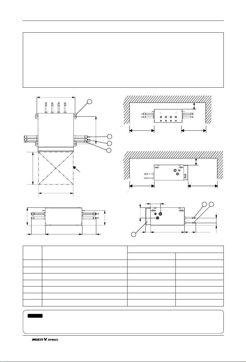
■ Select installation location of the HR unit suitable for following conditions
• Avoid a place where rain may enter since the HR unit is for indoor.
• Sufficient service space must be obtained.
• Refrigerant pipe must not exceed limited length.
• Avoid a place subject to a strong radiation heat from other heat source.
• Avoid a place where oil spattering, vapor spray or high frequency electric noise is expected.
• Install the unit at a place in which it is not affected by operation noise. (Installation within cell such as meeting
room etc. may disturb business due to noise.)
• Place where refrigerant piping, drain piping and electrical wiring works are easy.
100 more
(Serviceing space)
100mm(3-15/16 inch) more
(Serviceing space)
100 more
(Serviceing space)
e100mm(3-15/16 inch) more
(Serviceing space)
e
:
1. Be sure to install the inspection door at the control box side.
2. If reducers are used, servicing space must be increased equal to reducer's dimension.
NOTICE
(Unit: mm(inch))
Description
PRHR030A/040A PRHR020A
1 Low pressure Gas pipe connection port Ø28.58(1-1/8) Brazing connection Ø22.2(7/8) Brazing connection
2 High pressure Gas pipe connection port Ø22.2(7/8) Brazing connection Ø19.05(3/4) Brazing connection
3 Liquid pipe connection port Ø12.7(1/2) Brazing connection Ø9.52(3/8) Brazing connection
4 Indoor unit Gas pipe connection port Ø15.88(5/8) Brazing connection Ø15.88(5/8) Brazing connection
5 Indoor unit Liquid pipe connection port Ø9.52(3/8) Brazing connection Ø9.52(3/8) Brazing connection
6 Control box - 7 Hanger metal M10 or M8 M10 or M8
Part NameNo.
481(18-10/11)
7
100 more
100mm(3-15/16 inch) more
100mm(3-15/16 inch) more
(Serviceing space)
(Serviceing space)
(Serviceing space)
345(13-1/2)
300mm(11-7/8 inch) more
1
(Servicing space)
(NOTICE 2)
300mm(11-7/8 inch) more
(Servicing space)
2
3
100mm(3-15/16 inch) mor
100mm(3-15/16 inch) mor
100 more
(Serviceing space)
(Serviceing space)
(Serviceing space)
450(17-3/4)
218(8-1/2)
174(6-7/8)
450(17-3/4)
453(17-7/8)
Inspection door(NOTICE 1)
(servicing space)
(Servicing space)
182(7-1/8)
174(6-7/8)
300mm(11-7/8 inch)more
6
(NOTICE 2)
124(4-7/8)
128(5)
61(2-7/16)
419(16-1/2)
450mm(17-3/4 inch) more
(Servicing space)
54
137(5-3/8)
30(1-1/6)
60(2-3/8)
ENGLISH
Installation Manual 15
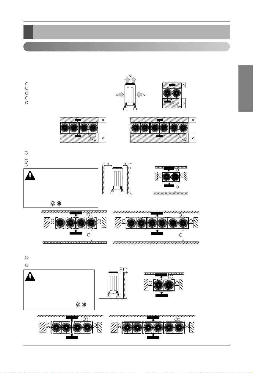
Installation Space
Installation Space
Individual Installation
■ Basic space required
A space of at least 250mm(9-13/16 inch) is necessary at the back for inlet air. Taking servicing, etc. from the
rear into account, a space of about 915mm(36 inches) should be provided, the same as at the front.
915mm(36 inches) or more (Control box is open/close type)
250mm(9-13/16 inch) or more
Top discharge (open in principle)
Front inlet (open in principle)
Rear inlet (open in principle)
A
B
C
D
E
A
B
C
915mm(36 inches) or more
(Control box is open/close type)
250mm(9-13/16 inch) or more
150mm(5-7/8 inch) from the wall
A
B
250mm(9-13/16 inch) or more
(350mm(13-3/4 inch)or more at the coastal area.)
150mm(5-7/8 inch) from the wall
B
A
Control Box
Front Side
Rear Side
B
A
Control Box
Front Side
Rear Side
A
B
Control Box
Front Side
Rear Side
C
A
B
C
A
B
h
H
Front Side
Rear Side
C
A
B
C
Front Side
Rear Side
C
A
B
C
Front Side
Rear Side
< Side view > < Top view >
< Side view > < Top view >
C
ED
B
A
B
A
h
H
Front Side
Rear Side
B
A
B
Front Side
Rear Side
B
A
B
Front Side
Rear Side
< Side view > < Top view >
CAUTION
Wall height(H) must not exceed height
of the product. If the wall height is higher than the whole height of product by
(h), Add (h) to
, .
CAUTION
Wall height(H) must not exceed
height of the product. If the wall
height is higher than the whole height
of product by (h), Add (h) to
, .
■ When inlet air enters from right and left sides of unit

16 Outdoor Unit
Installation Space
45° or more
200mm(7-7/8 inch)
or more
250mm(9-13/16 inch)
or more
A
B
C
Air guide
Air outlet guide
(Procured at the site)
250mm(9-13/16 inch)
or more
D
E
F
A
B
C
A
B
C
A
B
C
< Front view >
< Front view >
C
< Side view >
E
D
A
Front Side
B
Rear
Side
Door
< Air guide >
587.6(23-1/8)587.6(23-1/8)587.6(23-1/8)
372.5(14-11/16)
390(15-3/8)
125(4-15/16)
723.5(28-1/2)
■ When unit is surrounded by walls
915mm(36 inches) or more (Control box is of a open/close type)
250mm(9-13/16 inch) or more
A
B
A
B
B
B
Front Side
Rear Side
A
B
B
B
Front Side
Rear Side
A
B
B
B
Front Side
Rear Side
■ When there is an obstruction above the unit
ENGLISH
Installation Manual 17
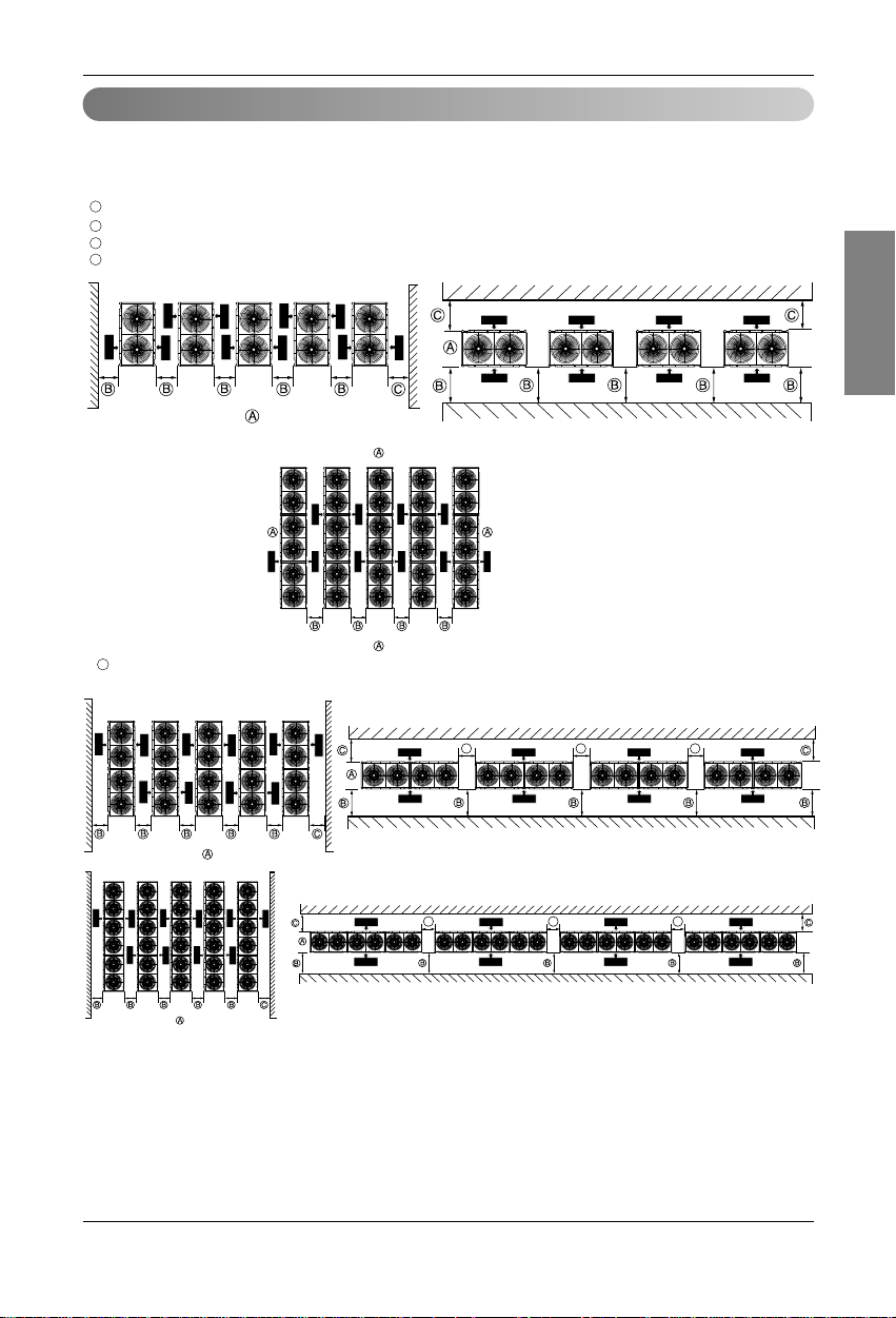
Installation Space
Collective / Continuous installation
Space required for collective installation and continuous installation:When installing several units, leave
space between each block as shown below considering passage for air and people.
(Be opened)
915mm(36 inches) or more (control box is of a open/close type)
250mm(9-13/16 inch) or more
A
B
C
150mm(5-7/8 inch) or more
D
Front Side
Rear Side
Rear Side
Front Side
Rear Side
Front Side
Rear Side
Front Side
Rear Side
Front Side
Rear Side
Front Side
Rear Side
Front Side
Rear Side
Front Side
Rear Side
Front Side
Rear Side
Front Side
Rear Side
Front Side
Rear Side
Front Side
Rear Side
Front Side
Rear Side
Front Side
Rear Side
Front Side
Rear Side
Front Side
Rear Side
Front Side
Front Side
Rear Side
Front Side
Rear Side
Front Side
Rear Side
Front Side
Rear Side
Front Side
Rear Side
Front Side
Rear Side
Front Side
Rear Side
Front Side
Rear Side
Front Side
Rear Side
Front Side
Rear Side
D D D
DDD
Front Side
Rear Side
Front Side
Rear Side
Front Side
Rear Side
Front Side
Rear Side
Front Side
Rear Side
= 1250mm(49-1/4 inch) or more
at the coastal area
or strong wind area
B
❈

18 Outdoor Unit
Installation Space
Seasonal wind and cautions in winter
• Sufficient measures are required in a snow area or severe cold area in winter so that product can be operated
well.
• Get ready for seasonal wind or snow in winter even in other areas.
• Install a suction and discharge duct not to let in snow or rain.
• Install the outdoor unit not to come in contact with snow directly. If snow piles up and freezes on the air suction
hole, the system may malfunction. If it is installed at snowy area, attach the hood to the system.
• Install the outdoor unit at the higher installation console by 50cm(19.6 inch) than the average snowfall (annual
average snowfall) if it is installed at the area with much snowfall.
• Where snow accumulated on the upper part of the Outdoor Unit by more than 10cm(3.9 inch), always remove
snow for operation.
1. The height of H frame must be more than 2 times the snowfall and its width shall not exceed the width of the
product. (If width of the frame is wider than that of the product, snow may accumulate)
2. Don't install the suction hole and discharge hole of the Outdoor Unit facing the seasonal wind.

ENGLISH
Installation Manual 19
Lifting Method
• When carrying the suspended, unit pass the ropes under the unit and use the two suspension points each at
the front and rear.
• Always lift the unit with ropes attached at four points so that impact is not applied to the unit.
• Attach the ropes to the unit at an angle of 40° or less.
Lifting method
CAUTION
Be very careful while carrying the product.
• Do not have only one person carry product if it is more than 20 kg(44 lbs).
• PP bands are used to pack some products. Do not use them as a mean for transportation because they
are dangerous.
• Do not touch heat exchanger fins with your bare hands. Otherwise you may get a cut in your hands.
• Tear plastic packaging bag and scrap it so that children cannot play with it. Otherwise plastic packaging
bag may suffocate children to death.
• When carrying in Outdoor Unit, be sure to support it at four points. Carrying in and lifting with 3-point
support may make Outdoor Unit unstable, resulting in a fall.
• Be very careful while carrying ARUN076DT2. It will be tilted in right side.
Sub line
A
40° or less
WARNING
20 Outdoor Unit
Installation
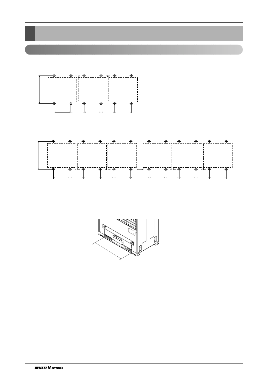
Location of anchor bolt(To be applied to 1, 2, 3 Units installation)
Installation
■ Individual installation
■ Collective installation
■ Installation foot(Location of anchor bolt)
Unit: mm(inch)
UW1 UW1 UW1
700±2
(27-9/16±1/16)
UW1 UW1 UW1 UW1 UW1 UW1
10(3/8) 10(3/8)
383
(15-1/16)
700±2(27-9/16±1/16)
900±2
(35-7/16±1/16)
383
(15-1/16)
900±2
(35-7/16±1/16)
900±2
(35-7/16±1/16)
900±2
(35-7/16±1/16)
10(3/8)
383
(15-1/16)
900±2
(35-7/16±1/16)
10(3/8)
383
(15-1/16)
900±2
(35-7/16±1/16)
900±2
(35-7/16±1/16)
10(3/8)
383
(15-1/16)
900±2
(35-7/16±1/16)
900±2
(35-7/16±1/16)
10(3/8)
383
(15-1/16)
150
(5-7/8)
533
(20-15/16)
900mm
(35-7/16 inch)
(UW1)
ENGLISH
Installation Manual 21
Installation
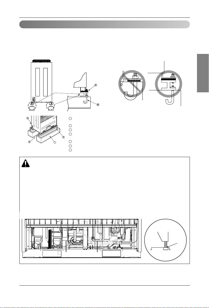
Foundation for Installation
• Fix the unit tightly with bolts as shown below so that unit will not fall down due to earthquake or gust.
• Use the H-beam support as a base support
• Noise and vibration may occur from the floor or wall since vibration is transferred through the installation
part depending on installation status. Thus, use anti-vibration materials (cushion pad) fully (The base pad
shall be more than 200mm(7.8 inch)).
A
B
D
E
F
G
C
Ensure that the corner part can be securely mounted. Otherwise, the support for
installation may be bent.
Obtain and use the M10 anchor bolt.
The corner was not properly mounted.
Outdoor unit (Insert the cushion pad between outdoor unit and base support to ensure that
anti-vibration may be done in a wide area)
Pipe and wiring space (in case of piping and wiring on the floor surface)
H-Beam support
Concrete base support
G
WARNING
• Be sure to install unit in a place strong enough to withstand its weight.
Any lack of strength may cause unit to fall down, resulting in a personal injury.
• Have installation work in order to protect against a strong wind and earthquake. Any installation
deficiency may cause unit to fall down, resulting in a personal injury.
• Especially take care for support strength of the floor surface, water drain processing (processing of
water flown out from the outdoor unit during operation) and paths of the pipe and wiring when making a base support.
• Don't use a tube or pipe for water drain in the base pan and perform water drain processing by
using the drain path. Water drain may not be done due to freezing of a tube or pipe.
Rear view
Side view
Water
Drain
Path
22 Outdoor Unit
Refrigerant piping installation
WARNING
After completing work, securely tighten both service ports and caps so that gas does not leak.
Refrigerant piping installation
WARNING
Always use extreme care to prevent the refrigerant gas (R410A) from leakage while using fire or
flame. If the refrigerant gas comes in contact with the flame from any source, such as a gas stove, it
breaks down and generates a poisonous gas which can cause gas poisoning. Never perform brazing
in an unventilated room. Always conduct an inspection for gas leakage after installation of the refrigerant piping has been completed.
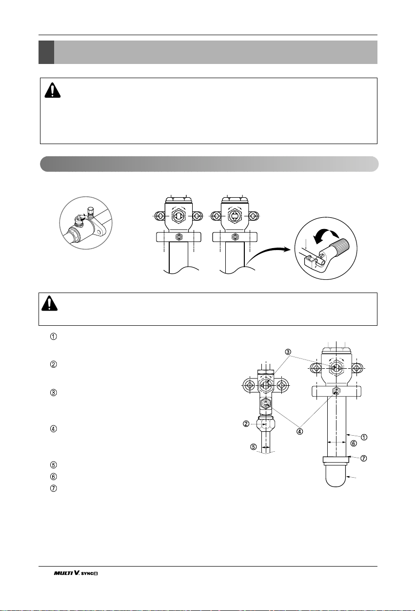
Pipe joint (auxiliary parts): Securely perform brazing with
a nitrogen blow into the service valve port.(Releasing
pressure : 0.29 psi or less)
Flare nut: Loose or tighten flare nut by using the wrench
with both ends. Coat the flare connection part with oil for
the compressor.
Cap: Remove caps and operate valve, etc. After operation, always reattach caps (tightening torque of valve
cap: 25Nm (250kg-cm) or more). (Don't remove the
internal part of the port)
Service port: Make the refrigerant pipe vacuum and
charge it using the service port. Always reattach caps
after completing work (tightening torque of service cap:
10 lbf
•
ft or more).
Liquid pipe
Gas pipe
Elbow joint (field supply)
Cautions in pipe connection/valve operation
Open status when both the pipe and
the valve are in a straight line.
Cut both the pipe and the valve with a
cutter to suit the length
(Don't cut the length of less than
70mm(2.8inch))
CLOSE OPEN
Elbow
Ball Valve(Gas Pipe)
Ball Valve(Liquid Pipe)
ENGLISH
Installation Manual 23
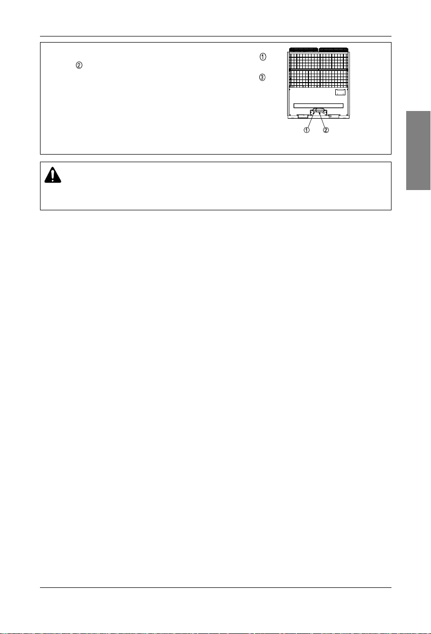
Refrigerant piping installation
When connecting the pipes from the front of the outdoor unit, remove part
and part .
When connecting the pipes from the side of the outdoor unit, remove part
(the whole "Knock out" part).
(Front)
WARNING
After installing the pipe, clog the pipe excavation inlet of the front panel and the side panel
(Wire may be damaged due to entering of rats, animals, etc).
24 Outdoor Unit
Refrigerant piping installation
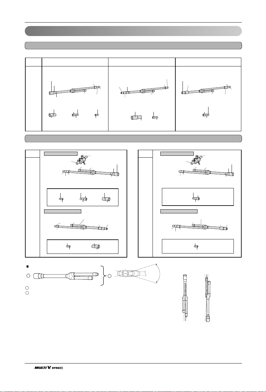
2 outdoor units
3 outdoor units
Connection of Outdoor Units
Model
Low Pressure Gas Pipe Liquid Pipe High Pressure Gas Pipe
[Unit:mm(inch)]
Ø34.9(1-3/8)
Ø31.8(1-1/4)
ARCNB20
Ø28.58(1-1/8)
OD34.9(1-3/8)
Ø38.1(1-1/2)
Model
Connection of gas pipe
Don't cut the pipe less
than 70mm
Ø19.05(3/4)
Ø15.88(5/8)
OD19.05(3/4)
ARCNN20
Connection of liquid pipe
Ø9.52(3/8)
Ø12.7(1/2)
OD28.58(1-1/8)
Ø22.2(7/8)
Ø
28.58(1-1/8)
Ø22.2(7/8)
Ø12.7(1/2)
Ø9.52(3/8)
OD12.7(1/2)
Ø28.58(1-1/8)
Ø28.58(1-1/8)
Ø19.05(3/4)
OD19.05(3/4)
Ø
28.58(1-1/8)
Ø19.05(3/4)
OD28.58
Ø22.2(7/8)
Sub1 outdoor unit
OD19.05(3/4)
Ø19.05(3/4)
Ø22.2(7/8)
Ø15.88(5/8)
Blow nitrogen
while brazing
Sub1 outdoor
gas pipe
OD34.9(1-3/8)
Ø38.1(1-1/2)
Ø19.05(3/4)
Ø15.88(5/8)
Ø22.2(7/8)
Ø12.7(1/2)
Ø
34.9(1-3/8)
Ø
31.8(1-1/4)
Ø
28.58(1-1/8)
Ø12.7(1/2)
Ø19.05(3/4)
Ø15.88(5/8)
Ø22.2(7/8)
OD19.05(3/4)
Ø12.7(1/2)
OD12.7(1/2)
Model
ARCNN30
Ø 9.52(3/8)
Ø12.7(1/2)
Ø9.52(3/8)
Ø22.2(7/8)
Connection of gas pipe
Don't cut the pipe less
than 70mm
Ø28.58(1-1/8)
Connection of liquid pipe
Ø12.7(1/2)
Ø15.88(5/8)
Ø28.58(1-1/8)
Ø34.9(1-3/8)
Ø19.05(3/4)
Ø12.7(1/2)
Ø19.05(3/4)
OD22.2(7/8)
Ø19.05(3/4)
Ø28.58(1-1/8)
OD28.58(1-1/8)
Ø22.2(7/8)
Main outdoor unit
Ø9.52(3/8)
OD12.7(1/2)
Ø22.2(7/8)
Ø15.88(5/8)
Blow nitrogen
while brazing
Main outdoor
gas pipe
Main pipe
Ø22.2(7/8) Ø19.05(3/4)
Main pipe
Ø19.05(3/4)
Ø15.88(5/8)
Ø22.2(7/8)
[Unit:mm(inch)]
Ø41.3(16-3/5)
Ø38.1(1-1/2)
Ø34.9(1-3/8)
Y branch
A
To outdoor unit
A
To branch piping or indoor unit
B
B
Viewed from point A
in direction of arrow
Within +/- 10°
Facing
downwards
Facing
upwards
Within ± 3° Within ± 3°

ENGLISH
Installation Manual 25
Refrigerant piping installation
Installation of Outdoor Unit, HR Unit, Indoor Unit Refrigerant Pipe
3 pipes are connected to the HR unit from the outdoor unit, classified into liquid pipe, low pressure gas pipe and
high pressure gas pipe depending on status of refrigerant passing through the pipe.
You must connect 3 pipes from outdoor unit to HR unit.
For connection between indoor unit and HR unit, you must connect both liquid pipe and gas pipe from the HR
unit to the indoor unit. In this case, connect them to the indoor unit starting from No.1 connection port of the HR
unit (the port number is displayed on ports of the HR unit). Use auxiliary flare as annexed parts in connection to
the indoor unit.
CAUTION:
Whenever connecting the indoor units with the HR unit, install the indoor units in numerical order from No.1.
Ex) In case of installing 3 indoor units : No. 1, 2, 3 (O), No. 1, 2, 4 (X), No.1, 3, 4 (X), No.2, 3, 4 (X).
Installation procedure for HR unit
Hanger metal
Flat washer
Hanging bolt
1. Using an insert-hole-in- anchor, hang the hanging bolt.
2. Install a hexagon nut and a flat washer (locally-procured)to the hanging bolt as shown
in the figure in the bottom, and fit the main unit to hang on the hanger metal.
3. After checking with a level that the unit is level, tighten the hexagon nut.
* The tilt of the unit should be within ±5° in front/back and left/right.
4. This unit should be installed suspended from ceiling and side A should always be
facing up.
5. Insulate not used pipes completely as shown in the figure.
Six-sided Nut
(M10 or M8)
Hanger metal
Hanger metal
Flat washer
Flat washer
(M10)
Hanging bolt
Hanging bolt
(M10 or M8)
A
Insulation
Gas pipe
HR Unit
2
1
Liquid pipe
4
3
Gas pipe
Liquid pipe
Liquid pipe
Low pressure
Gas pipe
High pressure
Gas pipe

26 Outdoor Unit
Refrigerant piping installation
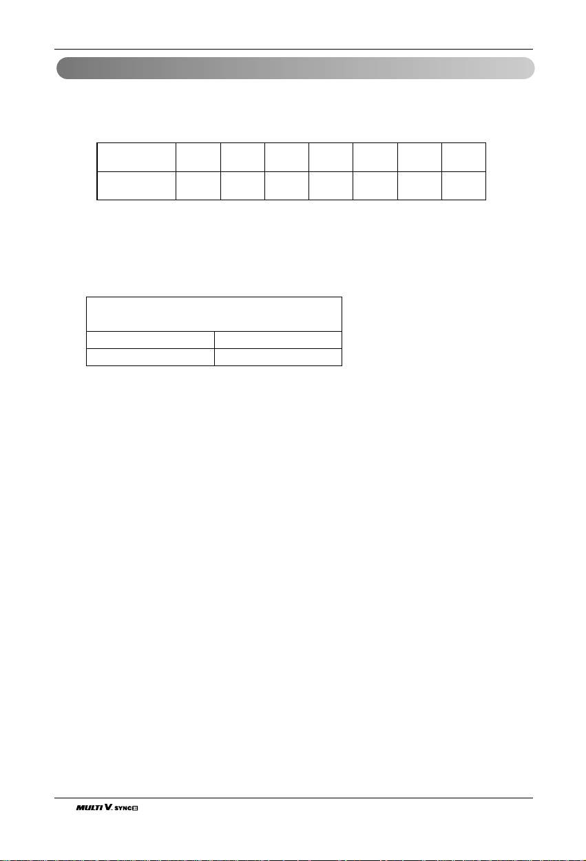
Select an HR unit according to the number of the indoor units to be installed. HR units are classified into 3 types
by the number of connectable indoor units.
Ex) Installation of 6 indoor units
Consists of HR unit for 4 rooms and HR unit for 2 rooms.
T ype of HR Unit
WARNING
• 1 port of HR unit allows up to 14.1kW based on cooling capacity of the indoor unit (up to 14.1kW
(48MBh) for max installation).
• The maximum total capacity of the indoor units connected to one PRHR040 HR unit is 47kW
(160MBh). In case of installation of four indoor units of 14.1kW (48MBh), use two PRHR020's rather
than one PRHR040.
HR unit PRHR020A PRHR030A PRHR040A
Low pressure gas pipe Ø22.2(7/8) Ø28.58(1-1/8) Ø28.58(1-1/8)
High pressure gas pipe Ø19.05(3/4) Ø22.2(7/8) Ø22.2(7/8)
Liquid pipe Ø9.52(3/8) Ø12.7(1/2) Ø12.7(1/2)
[Unit:mm(inch)]
4
2
1
PRHR030A(3 rooms)PRHR020A(2 rooms) PRHR040A(4 rooms)
3
2
1
Liquid pipe
3
2
1
Low pressure gas pipe
High pressure gas pipe
Remove caps on
The brazing part.
4
3
2
1
Gas pipe Ø15.88
Liquid pipe Ø9.52
Brazing Type

ENGLISH
Installation Manual 27
Refrigerant piping installation
[ Reducers for indoor unit and HR unit ]
Models
High pressure
Gas pipe
Low pressure
Liquid pipe
Indoor unit
reducer
HR unit
reducer
PRHR020A
OD22.2(7/8) Ø19.05(3/4)
Ø15.88(5/8)
OD15.88(5/8)
Ø12.7(1/2)
Ø6.35(1/4)OD9.52(3/8)
Ø6.35(1/4)OD9.52(3/8)
OD19.05(3/4) Ø15.88(5/8) Ø12.7(1/2)
OD22.2(7/8) Ø19.05(3/4)
Ø15.88(5/8)
PRHR030A
PRHR040A
OD15.88(5/8)
Ø12.7(1/2)
OD28.58(1-1/8) Ø22.2(7/8) Ø19.25(3/4)
OD12.7(1/2) Ø9.52(3/8)
OD12.7(1/2) Ø9.52(3/8)
OD15.88(5/8) Ø12.7(1/2)
OD19.05(3/4) Ø15.88(5/8)
[Unit:mm(inch)]
28 Outdoor Unit
Refrigerant piping installation
6.35(1/4) 9.52(3/8) 12.7(1/2) 15.88(5/8) 19.05(3/4) 22.2(7/8) 25.4(1)
0.8(0.03) 0.8(0.03) 0.8(0.03) 0.99(0.03) 0.99(0.03) 0.99(0.03) 0.99(0.03)
Minimum thickness
[mm(inch)]
Outer diameter
[mm(inch)]
1. Use the following materials for refrigerant piping.
• Material: Seamless phosphorous deoxidized copper pipe
• Wall thickness : Comply with the relevant local and national regulations for the designed pressure
3.8MPa. We recommend the following table as the minimum wall thickness.
2. Commercially available piping often contains dust and other materials. Always blow it clean with a
dry inert gas.
3. Use care to prevent dust, water or other contaminants from entering the piping during installation.
4. Reduce the number of bending portions as much as possible, and make bending radius as big as
possible.
5. Always use the branch piping set shown below, which are sold separately.
6. If the diameters of the branch piping of the designated refrigerant piping differs, use a pipe cutter to cut
the connecting section and then use an adapter for connecting different diameters to connect the piping.
7. Always observe the restrictions on the refrigerant piping (such as rated length, difference in height, and
piping diameter).
Failure to do so can result in equipment failure or a decline in heating/cooling performance.
8. The Multi V will stop due to an abnormality like excessive or insufficient refrigerant. At such a time, always
properly charge the unit. When servicing, always check the notes concerning both the pipe length and the
amount of additional refrigerant.
9. Never use refrigerant to perform an air purge. Always evacuate using a vacuum pump.
10. Always insulate the piping properly. Insufficient insulation will result in a decline in heating/cooling perfor-
mance, drip of condensate and other such problems.
11. When connecting the refrigerant piping, make sure the service valves of the outdoor unit is completely
closed (the factory setting) and do not operate it until the refrigerant piping for the outdoor and indoor
units has been connected, a refrigerant leakage test has been performed and the evacuation process
has been completed.
12. Always use a non-oxidizing brazing material for brazing the parts and do not use flux. If not, oxidized film
can cause clogging or damage to the compressors and flux can harm the copper piping or refrigerant oil.
13. Diameter of the refrigerant pipe from the HR unit to the indoor unit is determined by capacity of the
indoor unit. The pipe port is installed to suit a large capacity of the indoor unit for the connection flare of
the HR unit. It is sufficient to cut, connect and install the subsidiary flare to suit the pipe of the indoor unit
connected.
14. Take care so that there is no thermal damage on the service valves of the outdoor unit.
(Especially packing part of service port.) Wrap the service valve with a wet towel when brazing it.
Caution
ARBLB01621 ARBLB03321
ARBLB07121 ARBLB14521
Y branch
 Loading...