

LG ARUM096BTE5, ARUM144BTE5, ARUM192BTE5, ARUM121BTE5, ARUM168BTE5 Installation Manual
...
INSTALLATION MANUAL
Variable Refrigerant Flow Outdoor Units
6.0 to 42.0 Tons

PROPRIETARY DATA NOTICE
This document, as well as all reports, illustrations, data, information,
and other materials are the property of LG Electronics U.S.A., Inc., and are
disclosed by LG Electronics U.S.A., Inc. only in confidence.
Do not throw away, destroy, or lose this manual.
Please read carefully and store in a safe place for future reference.
Content familiarity is required for proper installation.
The instructions included in this manual must be followed to prevent product malfunction, property damage, injury, or death to the user or
other people. Incorrect operation due to ignoring any instructions will cause harm or damage. The level of seriousness is classified by the
symbols described by the summary list of safety precautions on page 4.
For more technical materials such as submittals, catalogs, engineering,
owner’s, best practices, and service manuals, visit www.lghvac.com.
For continual product development, LG Electronics U.S.A., Inc. reserves the right to change specifications without notice.
© LG Electronics U.S.A., Inc.
TABLE OF CONTENTS
Safety Precautions ............................................................................. 4-7
Unit Nomenclature ................................................................................. 8
Outdoor Unit Specications ............................................................ 9-18
208-230V Outdoor Units ................................................................. 9-13
460V Outdoor Units ...................................................................... 14-18
Electrical Data ................................................................................. 19-20
208-230V Outdoor Unit Electrical Data ............................................. 19
460V Outdoor Unit Electrical Data ..................................................... 20
Heat Recovery Specications / Electrical Data ................................ 21
Outdoor Unit Dimensions .............................................................. 22-25
Heat Recovery Unit Dimensions ................................................... 26-28
Transporting / Lifting .......................................................................... 29
Placement Considerations ............................................................ 30-37
Selecting the Best Location for the Outdoor Unit(s) ..................... 30-31
Outdoor Unit Clearance Requirements ............................................. 32
Installing Outdoor Units Indoors ................................................... 33-34
Installing and Setting Outdoor Units in Dual /
Triple Frame Systems ........................................................................ 35
Selecting the Best Location / Clearance Requirements for the
Heat Recovery Unit(s) .................................................................. 36-37
Mounting / Anchoring the Outdoor Unit(s) ...................................38-39
Mounting / Anchoring the Heat Recovery Unit(s) ............................. 40
General Refrigerant Piping System Information ......................... 41-53
LG Air Conditioner Technical Solution (LATS) ..............................41-42
Refrigerant Safety Standards / Device
Connection Limitations ...................................................................... 43
Selecting Copper Piping .................................................................... 44
Copper Expansion and Contraction .............................................. 45-47
Piping Handling ................................................................................. 48
Refrigerant System Engineering ................................................... 49-51
Flaring and Brazing Procedures ................................................... 52-53
Installing for Heat Pump Operation .............................................. 54-67
Indoor Unit Y-Branch Kits.............................................................. 54-55
Outdoor Unit Y-Branch Kits ........................................................... 56-57
Header Kits ................................................................................... 58-59
Sample Layouts ............................................................................ 60-63
Piping Connections / Pipe Routes ..................................................... 64
Knock Outs ....................................................................................... 65
Removing the Leak Prevention Caps ................................................ 66
Service Ports ..................................................................................... 67
Installing for Heat Recovery Operation ........................................ 68-89
Indoor Unit Y-Branch Kits.............................................................. 68-69
Outdoor Unit Y-Branch Kits ........................................................... 70-71
Header Kits ................................................................................... 72-73
Heat Recovery Units ..................................................................... 74-79
Sample Layouts ............................................................................ 80-85
Piping Connections / Pipe Routes ..................................................... 86
Knock Outs ....................................................................................... 87
Removing the Leak Prevention Caps ................................................ 88
Service Ports ..................................................................................... 89
Refrigerant Piping for Separated Outdoor Units ......................... 90-92
Insulation ......................................................................................... 93-95
Electrical ........................................................................................ 96-110
General Information ...................................................................... 96-97
Power Wiring and Communication Cable Terminations ................ 98-99
Power Wiring and Communication Cable Connections ................... 100
Power Wiring and Communication Cable
System Layout ................................................................................. 101
Power Supply / Power Wiring Specications ............................ 102-105
Communication Cable Specications ....................................... 106-110
Pre-Commissioning .....................................................................111-157
Triple Leak / Pressure Check ....................................................111- 113
Triple Evacuation Procedure .....................................................114-116
Vacuum Mode (Option) .....................................................................117
Pre-commissioning Start / Outdoor Unit
DIP Switch Settings ..........................................................................118
DIP Switch Settings for Use With Gen 4 Indoor Units ......................119
Setting the Optional Modes ...................................................... 120-134
Self Diagnostics Check .................................................................... 135
Indoor Unit Auto Addressing ..................................................... 136-138
Group Controlling Indoor Units ........................................................ 138
Central Control ......................................................................... 139-141
Addressing with Heat Recovery Units ...................................... 141-153
Temperature Sensing Location ................................................. 154-155
Setting External Static Pressure ............................................... 155-156
Package Pre-commissioning Documents /
Initiate a Request ............................................................................. 157
Error Codes ................................................................................. 159-168
LG Monitoring View (LGMV) Diagnostic Software .................. 169-170
Maintenance Recommendations ...................................................... 171
Checklists .................................................................................... 172-182
Due to our policy of continuous product innovation, some specifications may change without notification.
©LG Electronics U.S.A., Inc., Englewood Cliffs, NJ. All rights reserved. “LG” is a registered trademark of LG Corp.
3
DANGER
WARNING
CAUTION
SAFETY PRECAUTIONS
DANGER
WARNING
The instructions below must be followed to prevent product malfunction, property damage, injury or death to the user or other people. Incorrect operation due to ignoring any instructions will cause harm or damage. The level of seriousness is classified by the symbols described
below.
TABLE OF SYMBOLS
This symbol indicates an imminently hazardous situation which, if not avoided, will result in death or serious injury.
This symbol indicates a potentially hazardous situation which, if not avoided, could result in death or serious injury.
This symbol indicates a potentially hazardous situation which, if not avoided, may result in minor or moderate injury.
This symbol indicates situations that may result in equipment or property damage accidents only.
This symbol indicates an action that should not be performed.
INSTALLATION
Do not store or use ammable gas or combustibles near
the unit.
There is risk of re, explosion, and physical injury or death.
Do not install, remove, or re-install the unit by yourself
(end user). Ask the dealer or an LG trained technician to
install the unit.
Improper installation by the user may result in re, explosion, electric
shock, physical injury or death.
For replacement of an installed unit, always contact an LG
trained service provider.
There is risk of re, electric shock, explosion, and physical injury or
death.
MULTI V 5 Outdoor Unit Installation Manual
Wear protective gloves when handling equipment. Sharp
edges may cause personal injury.
Do not change the settings of the protection devices.
If the protection devices have been bypassed or are forced to operate
improperly, or parts other than those specied by LG are used, there is
risk of re, electric shock, explosion, and physical injury or death.
Replace all control box and panel covers.
If cover panels are not securely installed, dust, water, and animals may
enter the outdoor unit, causing re, electric shock, and physical injury or
death.
Always check for system refrigerant leaks after the unit has
been installed or serviced.
Exposure to high concentration levels of refrigerant gas may lead to
illness or death.
Do not supply power to the unit until all wiring and piping
are completed or reconnected and checked.
There is risk of physical injury or death due to electric shock.
If the air conditioner is installed in a small space, take
measures to prevent the refrigerant concentration from
exceeding safety limits in the event of a refrigerant leak.
Consult the latest edition of American Society of Heating,
Refrigerating, and Air Conditioning Engineers (ASHRAE) Standard 15.
If the refrigerant leaks and safety limits are exceeded, it could result in
personal injuries or death from oxygen depletion.
The heat recovery unit must be installed indoors; do not
install the heat recovery unit in a highly humid environment.
There is risk of physical injury or death due to electric shock.
Dispose of the packing materials safely.
• Packing materials, such as nails and other metal or wooden parts,
may cause puncture wounds or other injuries.
• Tear apart and throw away plastic packaging bags so that children
may not play with them and risk suffocation and death.
Install the unit considering the potential for strong winds or
earthquakes.
Improper installation may cause the unit to fall over, resulting in physical
injury or death.
Install the unit in a safe location where nobody can step, fall
onto it, or place objects on it.
defective stand.
It may result in an accident that causes physical injury or death.
Do not install the unit on a
Periodically check that the outdoor frame is not damaged.
There is a risk of explosion, physical injury, or death.
4
Due to our policy of continuous product innovation, some specifications may change without notification.
©LG Electronics U.S.A., Inc., Englewood Cliffs, NJ. All rights reserved. “LG” is a registered trademark of LG Corp.
SAFETY PRECAUTIONS
CAUTION
WARNING
Properly insulate all cold surfaces to prevent “sweating.”
Cold surfaces such as uninsulated piping can generate condensate that could drip, causing a slippery surface that creates a risk of slipping, falling,
and personal injury.
Be very careful when transporting the product. There is a risk of the product falling and causing physical injury.
• Use appropriate moving equipment to transport each frame; ensure the equipment is capable of supporting the weights listed.
• Some products use polypropylene bands for packaging. Do not use polypropylene bands to lift the unit.
• Suspend the outdoor unit from the base at specified positions (at a minimum of six [6] points) to avoid slippage from rigging apparatus.
LG Electronics U.S.A., Inc., is not responsible for any piping
calculations, refrigerant leaks, degradation of performance,
or any other potential problems or damages as a result of
interconnecting piping, their joint connections, isolation
valves, introduced debris inside the piping system, or other
problems caused by the interconnecting piping system.
Do not install the product where it is exposed directly to
ocean winds.
Sea salt in the air may cause the product to corrode. Corrosion,
particularly on the condenser and evaporator ns, could cause product
malfunction or inefcient operation.
When installing the outdoor unit in a low-lying area, or a location that is not level, use a raised concrete pad or concrete
blocks to provide a solid, level foundation.
This prevents water damage and abnormal vibration.
Properly insulate all cold surfaces to prevent “sweating.”
Cold surfaces such as uninsulated piping can generate condensate that
may drip and cause a slippery surface condition and / or water damage
to walls.
Always check for system refrigerant leaks after the unit has
been installed or serviced.
Low refrigerant levels may cause product failure.
Do not make refrigerant substitutions. Use R410A only.
If a different refrigerant is used, or air mixes with original refrigerant, the
unit will malfunction and damage will occur.
Keep the unit upright during installation to avoid vibration or
water leakage.
When installing the unit in a hospital, mechanical room, or
similar electromagnetic eld (EMF) sensitive environment,
provide sufcient protection against electrical noise.
Inverter equipment, power generators, high-frequency medical equipment or radio communication equipment may cause the air conditioner
to operate improperly. The unit may also affect such equipment by
creating electrical noise that disturbs medical treatment or image broadcasting.
The heat recovery box must be installed indoors; do not
install the heat recovery box in a highly humid environment.
There is risk of product failure and property damage.
When connecting refrigerant piping, remember to allow for
pipe expansion.
Improper piping installation may cause system malfunction.
Do not install the outdoor unit or heat recovery unit in a
noise-sensitive area.
Take appropriate actions at the end of HVAC equipment life
to recover, recycle, reclaim, or destroy R410A refrigerant
according to applicable U.S. Environmental Protection
Agency (EPA) rules.
Periodically check that the outdoor frame is not damaged.
There is a risk of equipment damage.
Safety Precautions
Do not store or use ammable gas / combustibles near
the unit.
There is a risk of product failure.
Do not use the product for mission critical or special purpose applications such as preserving foods, works of art, or
other precision air conditioning applications. The equipment
is designed to provide comfort cooling and heating.
There is risk of property damage.
Due to our policy of continuous product innovation, some specifications may change without notification.
©LG Electronics U.S.A., Inc., Englewood Cliffs, NJ. All rights reserved. “LG” is a registered trademark of LG Corp.
Install the unit in a safe location where no one can step on or
fall onto it.
Do not install the unit on a defective stand.
There is a risk of unit and property damage.
Install the drain hose to ensure adequate drainage.
There is a risk of water leakage and property damage.
5
SAFETY PRECAUTIONS
DANGER
WARNING
WIRING
High voltage electricity is required to operate this system.
Adhere to the U.S. National Electric Codes (NEC) and these
instructions when wiring.
Improper connections and inadequate grounding can cause accidental
injury or death.
Always ground the unit following local, state, and NEC codes.
There is risk of re, electric shock, and physical injury or death.
Turn the power off at the nearest disconnect before servicing
the equipment.
Electrical shock can cause physical injury or death.
The information contained in this manual is intended for use
by an industry-qualied, experienced, trained electrician
familiar with the NEC who is equipped with the proper tools
and test instruments.
Failure to carefully read and follow all instructions in this manual can
result in personal injury or death.
All electric work must be performed by a licensed electrician
and conform to local building codes or, in the absence of
local codes, with the NEC, and the instructions given in this
manual.
If the power source capacity is inadequate or the electric work is not
performed properly, it may result in re, electric shock, physical injury or
death.
MULTI V 5 Outdoor Unit Installation Manual
Refer to local, state, and federal codes, and use power wires
of sufcient current capacity and rating.
Wires that are too small may generate heat and cause a re, and physical injury or death.
Properly size all circuit breakers or fuses.
There is risk of re, electric shock, explosion, physical injury or death.
Do not share the electrical circuit with other devices.
There is risk of re, electric shock, and physical injury or death due to
heat generation.
Do not use damaged or loose power wiring. Do not
modify or extend the outdoor unit’s power wiring. Ensure that
the power wiring will not be pulled nor weight be placed on
the power wiring during operation.
There is risk of re, electric shock, and physical injury or death.
Secure all eld wiring connections with appropriate wire
strain relief.
Improperly securing wires will create undue stress on equipment power
connections. Inadequate connections may generate heat, cause a re,
and physical injury or death.
Ensure the system is connected to a dedicated power source
that provides adequate power.
If the power source capacity is inadequate or the electric work is not
performed properly, it may result in re, electric shock, physical injury or
death.
Properly tighten all power connections.
Loose wiring may overheat at connection points, causing a re, physical
injury or death.
Do not change the settings of the protection devices.
If the protection devices have been bypassed or is forced to operate
improperly, or parts other than those specied by LG are used, there is
risk of re, electric shock, explosion, and physical injury or death.
Do not supply power to the unit until all electrical wiring,
controls wiring, piping, installation, and refrigerant system
evacuation are completed.
The system may malfunction.
6
Due to our policy of continuous product innovation, some specifications may change without notification.
©LG Electronics U.S.A., Inc., Englewood Cliffs, NJ. All rights reserved. “LG” is a registered trademark of LG Corp.
The information contained in this manual is intended for use
by an industry-qualied, experienced, licensed electrician
familiar with the NEC who is equipped with the proper tools
and test instruments.
Failure to carefully read and follow all instructions in this manual can
result in equipment malfunction and property damage.
OPERATION
DANGER
WARNING
CAUTION
SAFETY PRECAUTIONS
Do not provide power to or operate the unit if it is ooded
or submerged.
There is risk of re, electric shock, physical injury or death.
Use a dedicated breaker for this product.
There is risk of re, electric shock, physical injury or death.
Do not operate the disconnect switch with wet hands.
There is risk of re, electric shock, physical injury or death.
Periodically verify the equipment mounts have not
deteriorated.
Use inert (nitrogen) gas when performing leak tests or air
purges.
gases.
Do not use compressed air, oxygen, or ammable
Using these substances may cause re, explosion, and physical injury
or death.
If refrigerant leaks out, ventilate the area before operating the
unit.
If the unit is mounted in an enclosed, low-lying, or poorly ventilated area,
and the system develops a refrigerant leak, it may cause a re, electric
shock, explosion, physical injury or death.
If the base collapses, the unit could fall and cause physical injury or death.
Do not allow water, dirt, or animals to enter the unit.
There is risk of re, electric shock, physical injury or death.
Do not operate the unit with the panel(s) or protective
cover(s) removed; keep ngers and clothing away from
moving parts.
Do not touch the refrigerant piping during or after
operation.
It can cause burns or frostbite.
Do not open the inlet during operation.
There is risk of electric shock, physical injury or death.
The rotating, hot, cold, and high-voltage parts of the unit can cause
physical injury or death.
To avoid physical injury, use caution when cleaning or servicing the air conditioner.
There is risk of electric shock, physical injury or death.
Safety Precautions
Clean up the site after servicing is nished, and check that
no metal scraps, screws, or bits of wiring have been left
inside or surrounding the unit.
Do not use the product for mission critical or special purpose applications such as preserving food, works of art, or
other precision air conditioning applications. The equipment
is designed to provide comfort cooling and heating.
There is risk of property damage.
Do not allow water, dirt, or animals to enter the unit.
There is risk of unit failure.
Do not open the inlet during operation.
There is risk of unit failure.
Do not operate the unit with the panel(s) or protective
cover(s) removed; keep ngers and clothing away from
moving parts.
Non-secured covers can result in malfunction due to dust or water in the
service panel.
Periodically verify the equipment mounts have not
deteriorated.
If the base collapses, the unit could fall and cause property damage or
product failure.
Due to our policy of continuous product innovation, some specifications may change without notification.
©LG Electronics U.S.A., Inc., Englewood Cliffs, NJ. All rights reserved. “LG” is a registered trademark of LG Corp.
Use only a soft cloth to clean the air conditioner. Do not
use wax, thinner, or strong detergents.
Strong cleaning products may damage the surface of the air conditioner,
or may cause its appearance to deteriorate.
Provide power to the outdoor unit to warn the compressor
crankcase at least six (6) hours before operation begins.
Starting operation with a cold compressor sump(s) may result in severe
bearing damage to the compressor(s). Keep the power switch on during
the operational season.
Do not turn off the main power switch after operation has
been stopped.
Wait at least ve (5) minutes before turning off the main power switch,
otherwise it may result in product malfunction.
Do not block the inlet or outlet.
Unit may malfunction.
Auto-addressing should be performed after connecting the
power of all indoor and outdoor units.
Auto-addressing should also be performed after servicing an indoor unit.
7
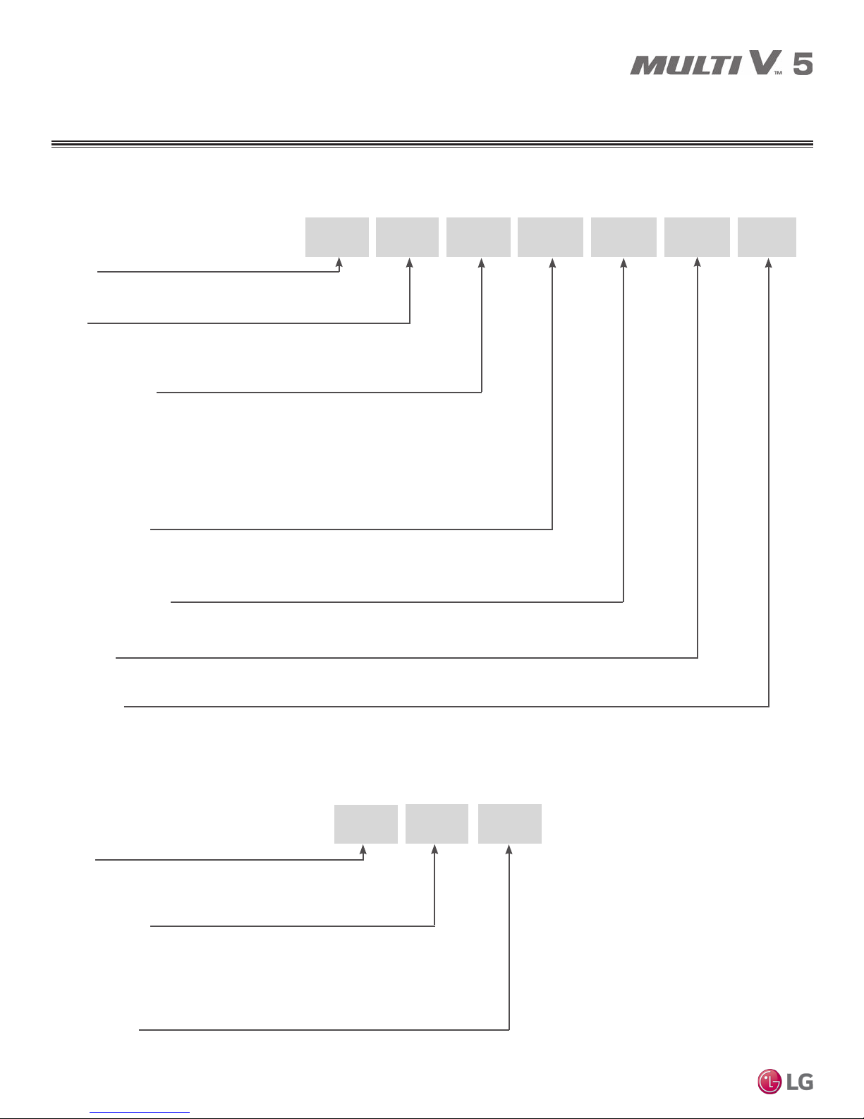
UNIT NOMENCLATURE
Outdoor Units and Heat Recovery Units
Outdoor Units (ODU)
Family
ARU = Multi V Outdoor Unit (Refrigerant R410A)
Type
M = Combination (Heat Pump or Heat Recovery)
Nominal Capacity
(Nominal cooling capacity in Btu/h)
072 = 72,000
096 = 96,000
121 = 121,000
144 = 144,000
168 = 168,000
Electrical Ratings
B = 208–230V/60Hz/3Ph
D = 460V/60Hz/3Ph
Airflow Configuration
T = Top Discharge
192 = 192,000
216 = 216,000
241 = 240,000
264 = 264,000
288 = 288,000
312/313 = 312,000
336/337 = 336,000
360 = 360,000
384 = 384,000
408 = 408,000
ARU
M 072 B T
432 = 432,000
456 = 456,000
480 = 480,000
504 = 504,000
E
5
Efficiency
E = High Efficiency
Generation
5 = Fifth
MULTI V 5 Outdoor Unit Installation Manual
Heat Recovery Units (HRU)
PRHR
Family
PRHR = Multi V Heat Recovery (HR) unit (Refrigerant R410A)
Number of Ports
02 = Two Ports
03 = Three Ports
04 = Four Ports
Series Number
2A = Series Number
02 2A
8
Due to our policy of continuous product innovation, some specifications may change without notification.
©LG Electronics U.S.A., Inc., Englewood Cliffs, NJ. All rights reserved. “LG” is a registered trademark of LG Corp.

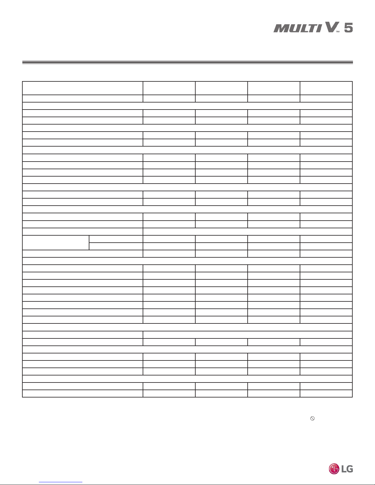
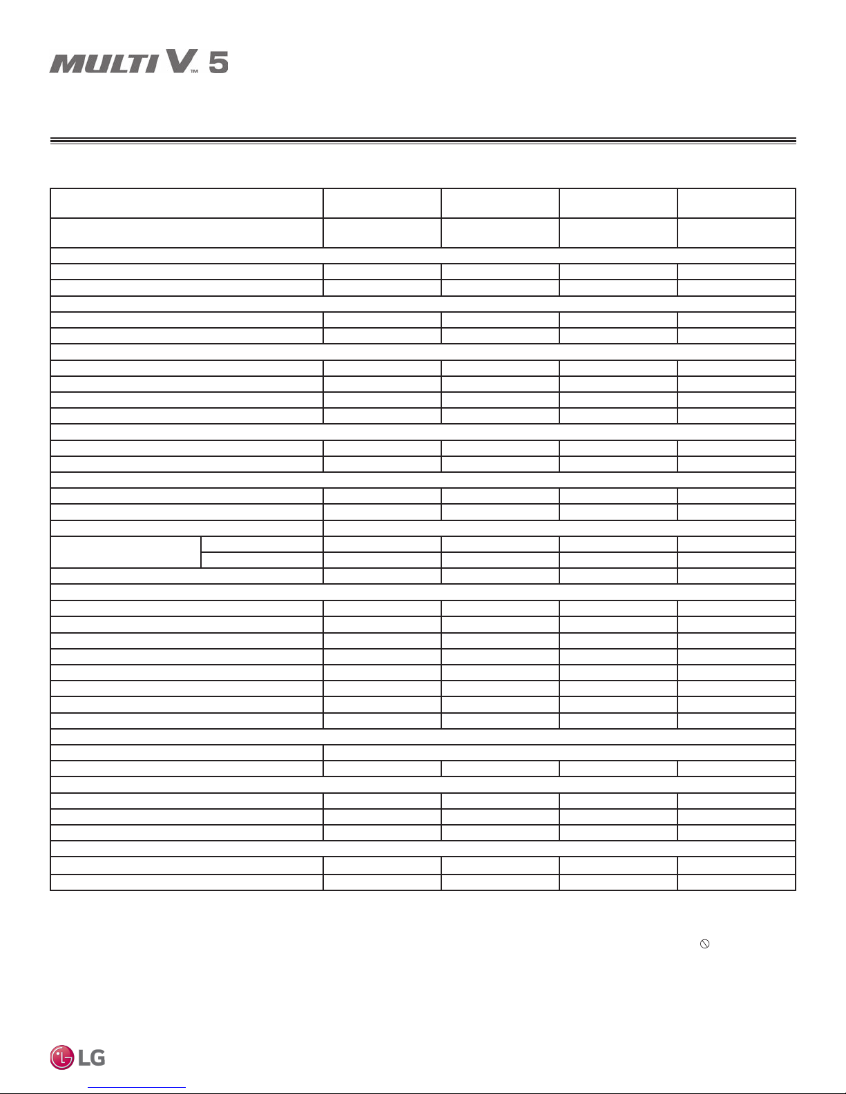
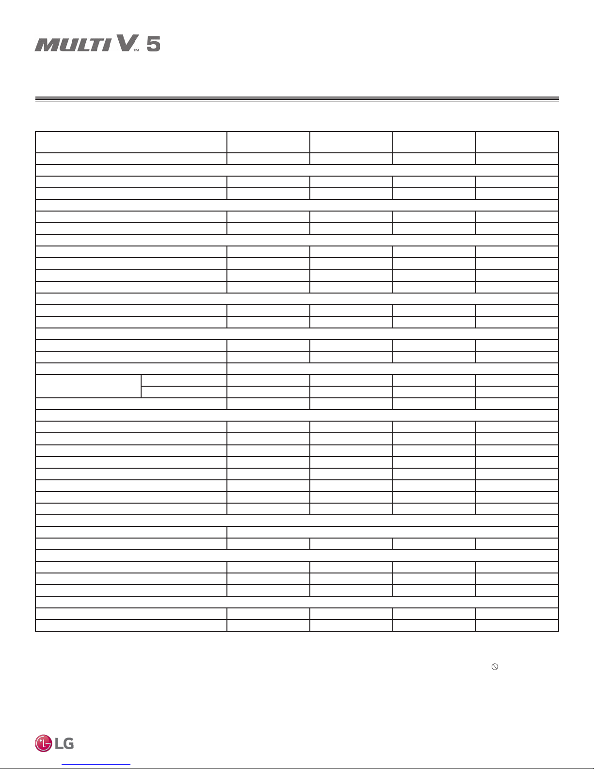
SPECIFICATIONS
208-230V Outdoor Units
Table 1: Single Frame 208-230V Outdoor Units.
Unit Model Number
ARUM072BTE5
6.0 Ton
Individual Component Model Numbers - - - -
Cooling Performance
Nominal Cooling Capacity (Btu/h)
Rated Cooling Capacity (Btu/h)
1
2
72,000 96,000 120,000 144,000
69,000 92,000 114,000 138,000
Heating Performance
Nominal Heating Capacity (Btu/h)
Rated Heating Capacity (Btu/h)
1
2
81,000 108,000 135,000 162,000
77,000 103,000 129,000 154,000
Operating Range
Cooling (°F DB) 5 to 122 5 to 122 5 to 122 5 to 122
Heating (°F WB) -13 to +61 -13 to +61 -13 to +61 -13 to +61
Synchronous — Cooling Based (°F DB) 14 to 81 14 to 81 14 to 81 14 to 81
Synchronous — Heating Based (°F WB) 14 to 61 14 to 61 14 to 61 14 to 61
Compressor
Inverter Quantity HSS DC Scroll x 1 HSS DC Scroll x 1 HSS DC Scroll x 1 HSS DC Scroll x 2
Oil/Type PVE / FVC68D PVE / FVC68D PVE / FVC68D PVE / FVC68D
Fan (Top Discharge)
Type Propeller (BLDC) Propeller (BLDC) Propeller (BLDC) Propeller (BLDC)
Motor Output (kW) x Qty. 1.5 x 1 0.9 x 2 0.9 x 2 0.9 x 2
Motor/Drive Brushless Digitally Controlled / Direct
Operating Range (RPM)
Cooling 0 - 1,000 0 - 1,150 0 - 1,150 0 - 1,150
Heating 80 - 1,000 80 - 1,150 80 - 1,150 80 - 1,150
Maximum Air Volume (CFM) 8,470 11,300 11,300 11,300
Unit Data
Refrigerant Type R410A R410A R410A R410A
Refrigerant Control/Location EEV / Indoor Unit EEV / Indoor Unit EEV / Indoor Unit EEV / Indoor Unit
Factory Charge lbs. of R410A 14.3 23.2 23.2 26.5
Max. No. Indoor Units/System
Sound Pressure dB(A)
3
4
13 16 20 24
58.0 58.0 59.0 60.0
Net Unit Weight (lbs.) 430 507 507 639
Shipping Weight (lbs.) 452 534 534 666
Communication Cables
5,6
2 x 18 2 x 18 2 x 18 2 x 18
Heat Exchanger
Material and Fin Coating Copper Tube / Aluminum Fin and Black Coated Fin™ / Hydrophilic
Rows / Fins per inch 2 / 17 2 / 17 2 / 17 3 / 17
Piping for Heat Recovery Operation
7
Liquid Line Connection (in., OD) 3/8 Braze 3/8 Braze 1/2 Braze 1/2 Braze
Low Pressure Vapor Line Connection (in., OD) 3/4 Braze 7/8 Braze 1-1/8 Braze 1-1/8 Braze
High Pressure Vapor Line Connection (in., OD) 5/8 Braze 3/4 Braze 3/4 Braze 7/8 Braze
Piping for Heat Pump Operation
7
Liquid Line Connection (in., OD) 3/8 Braze 3/8 Braze 1/2 Braze 1/2 Braze
Vapor Line Connection (in., OD) 3/4 Braze 7/8 Braze 1-1/8 Braze 1-1/8 Braze
1
Nominal capacity applied with non-ducted indoor units, and is rated 0 ft. above sea level
with 25 ft. of refrigerant line per indoor unit and a 0 ft. level difference between outdoor and
indoor units. All capacities are net with a Combination Ratio between 95–105%.
Nominal cooling capacity rating obtained with air entering the indoor unit at 80ºF dry bulb
(DB) and 67ºF wet bulb (WB) and outdoor ambient conditions of 95ºF dry bulb (DB) and
75ºF wet bulb (WB).
Nominal heating capacity rating obtained with air entering the indoor unit at 70ºF dry bulb
(DB) and 59ºF wet bulb (WB) and outdoor ambient conditions of 47ºF dry bulb (DB) and
43ºF wet bulb (WB).
2
Rated capacity is certied under AHRI Standard 1230. See www.ahrinet.org for information.
3
The System Combination Ratio must be between 50–130%.
ARUM096BTE5
8.0 Ton
4
Sound pressure levels are tested in an anechoic chamber under ISO Standard 3745.
5
Communication cable between Master ODU to Slave ODU(s), and Master ODU to IDUs /
HRUs to be 18 AWG, 2-conductor, twisted, stranded, shielded. Ensure the communication
cable shield is properly grounded to the Master ODU chassis only.
ODU to IDUs / HRUs communication cable at any other point. Wiring must comply with all
applicable local and national codes.
6
Power wiring is eld provided, solid or stranded, and must comply with the applicable
local and national codes. See page 19 for detailed electrical data.
7
LG requires that LATS software be used on all projects to ensure correct line sizing.
Designer must verify the shop drawing design against the as built design using LATS.
Contractor must also use LG manufactured Y-Branch and Header Kits only.
ARUM121BTE5
10.0 Ton
ARUM144BTE5
12.0 Ton
Do not ground the
Product Data
Due to our policy of continuous product innovation, some specifications may change without notification.
©LG Electronics U.S.A., Inc., Englewood Cliffs, NJ. All rights reserved. “LG” is a registered trademark of LG Corp.
9
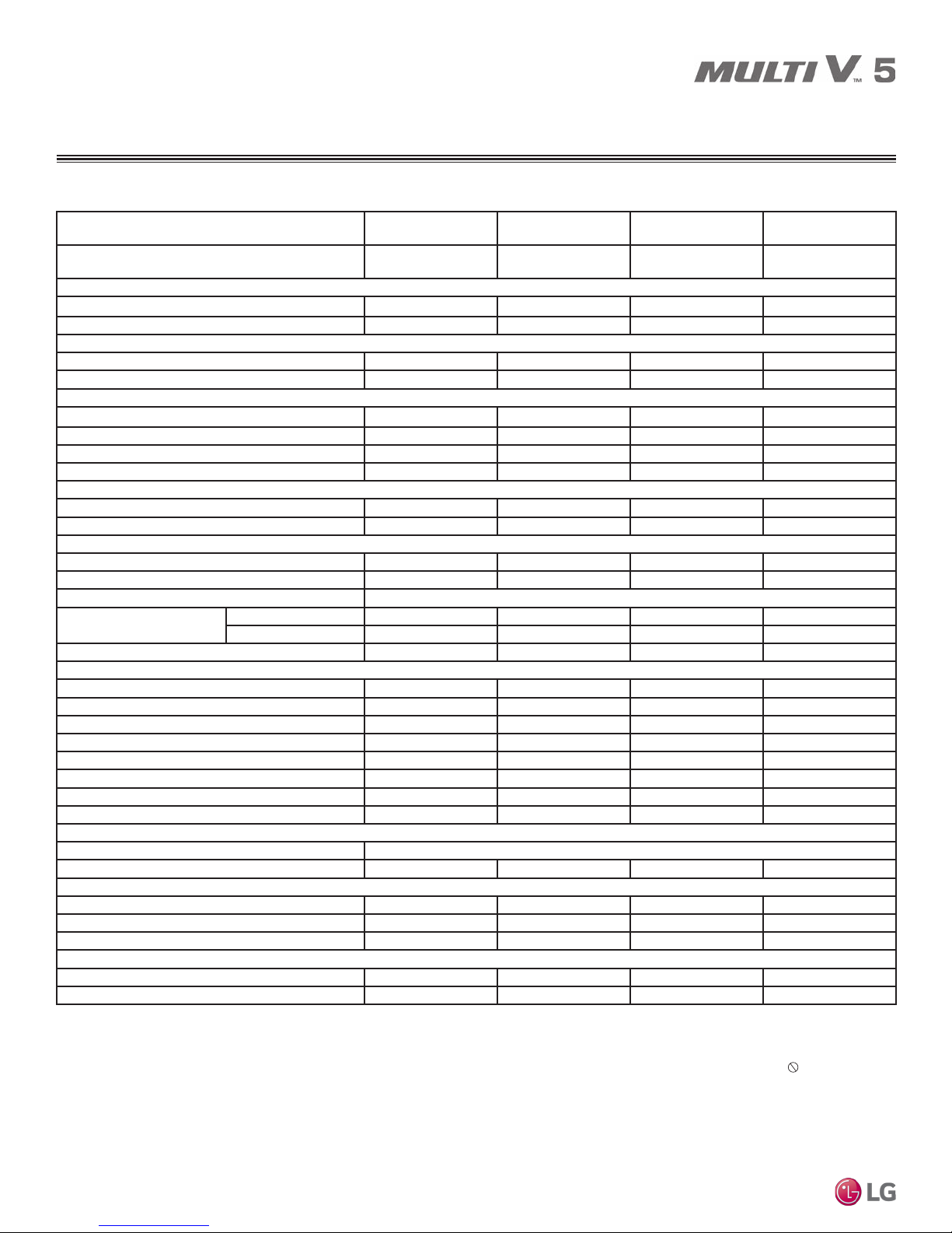
SPECIFICATIONS
208 / 230V Outdoor Units
Table 2: Single Frame 208-230V Outdoor Units, continued.
Unit Model Number
ARUM168BTE5
14.0 Ton
Individual Component Model Numbers - - - -
Cooling Performance
Nominal Cooling Capacity (Btu/h)
Rated Cooling Capacity (Btu/h)
1
2
168,000 192,000 216,000 240,000
160,000 184,000 206,000 222,000
Heating Performance
Nominal Heating Capacity (Btu/h)
Rated Heating Capacity (Btu/h)
1
2
189,000 216,000 243,000 243,000
180,000 206,000 230,000 230,000
Operating Range
Cooling (°F DB) 5 to 122 5 to 122 5 to 122 5 to 122
Heating (°F WB) -13 to +61 -13 to +61 -13 to +61 -13 to +61
Synchronous — Cooling Based (°F DB) 14 to 81 14 to 81 14 to 81 14 to 81
Synchronous — Heating Based (°F WB) 14 to 61 14 to 61 14 to 61 14 to 61
Compressor
Inverter Quantity HSS DC Scroll x 2 HSS DC Scroll x 2 HSS DC Scroll x 2 HSS DC Scroll x 2
Oil/Type PVE / FVC68D PVE / FVC68D PVE / FVC68D PVE / FVC68D
Fan (Top Discharge)
Type Propeller (BLDC) Propeller (BLDC) Propeller (BLDC) Propeller (BLDC)
Motor Output (kW) x Qty. 0.9 x 2 0.9 x 2 0.9 x 2 0.90 x 2
Motor/Drive Brushless Digitally Controlled / Direct
Operating Range (RPM)
Cooling 0 - 1,150 0 - 1,150 0 - 1,150 0 - 1,150
Heating 80 - 1,150 80 - 1,150 80 - 1,150 80 - 1,150
Maximum Air Volume (CFM) 11,300 11,300 11,300 11,300
Unit Data
Refrigerant Type R410A R410A R410A R410A
Refrigerant Control/Location EEV / Indoor Unit EEV / Indoor Unit EEV / Indoor Unit EEV / Indoor Unit
Factory Charge lbs. of R410A 26.5 30.9 37.5 37.5
Max. No. Indoor Units/System
Sound Pressure dB(A)
3
4
29 32 35 39
61.0 62.0 64.0 65.0
Net Unit Weight (lbs.) 639 659 666 666
Shipping Weight (lbs.) 666 688 694 694
Communication Cables
MULTI V 5 Outdoor Unit Installation Manual
Heat Exchanger
5,6
2 x 18 2 x 18 2 x 18 2 x 18
Material and Fin Coating Copper Tube / Aluminum Fin and Black Coated Fin™ / Hydrophilic
Rows / Fins per inch 3 / 17 3 / 17 3 / 17 3 / 17
Piping for Heat Recovery Operation
7
Liquid Line Connection (in., OD) 5/8 Braze 5/8 Braze 5/8 Braze 5/8 Braze
Low Pressure Vapor Line Connection (in., OD) 1-1/8 Braze 1-1/8 Braze 1-1/8 Braze 1-3/8 Braze
High Pressure Vapor Line Connection (in., OD) 7/8 Braze 1-1/8 Braze 1-1/8 Braze 1-1/8 Braze
Piping for Heat Pump Operation
7
Liquid Line Connection (in., OD) 5/8 Braze 5/8 Braze 5/8 Braze 5/8 Braze
Vapor Line Connection (in., OD) 1-1/8 Braze 1-1/8 Braze 1-1/8 Braze 1-3/8 Braze
1
Nominal capacity applied with non-ducted indoor units, and is rated 0 ft. above sea level
with 25 ft. of refrigerant line per indoor unit and a 0 ft. level difference between outdoor and
indoor units. All capacities are net with a Combination Ratio between 95–105%.
Nominal cooling capacity rating obtained with air entering the indoor unit at 80ºF dry bulb
(DB) and 67ºF wet bulb (WB) and outdoor ambient conditions of 95ºF dry bulb (DB) and
75ºF wet bulb (WB).
Nominal heating capacity rating obtained with air entering the indoor unit at 70ºF dry bulb
(DB) and 59ºF wet bulb (WB) and outdoor ambient conditions of 47ºF dry bulb (DB) and
43ºF wet bulb (WB).
2
Rated capacity is certied under AHRI Standard 1230. See www.ahrinet.org for information.
3
The System Combination Ratio must be between 50–130%.
ARUM192BTE5
16.0 Ton
4
Sound pressure levels are tested in an anechoic chamber under ISO Standard 3745.
5
Communication cable between Master ODU to Slave ODU(s), and Master ODU to IDUs /
HRUs to be 18 AWG, 2-conductor, twisted, stranded, shielded. Ensure the communication
cable shield is properly grounded to the Master ODU chassis only.
ODU to IDUs / HRUs communication cable at any other point. Wiring must comply with all
applicable local and national codes.
6
Power wiring is eld provided, solid or stranded, and must comply with the applicable
local and national codes. See page 19 for detailed electrical data.
7
LG requires that LATS software be used on all projects to ensure correct line sizing.
Designer must verify the shop drawing design against the as built design using LATS.
Contractor must also use LG manufactured Y-Branch and Header Kits only.
ARUM216BTE5
18.0 Ton
ARUM241BTE5
20.0 Ton
Do not ground the
10
Due to our policy of continuous product innovation, some specifications may change without notification.
©LG Electronics U.S.A., Inc., Englewood Cliffs, NJ. All rights reserved. “LG” is a registered trademark of LG Corp.
SPECIFICATIONS
208-230V Outdoor Units
Table 3: Dual Frame 208-230V Outdoor Units.
Unit Model Number
Individual Component Model Numbers
ARUM264BTE5
22.0 Ton
ARUM096BTE5 +
ARUM168BTE5
Cooling Performance
Nominal Cooling Capacity (Btu/h)
Rated Cooling Capacity (Btu/h)
1
2
264,000 288,000 312,000 336,000
252,000 276,000 298,000 320,000
Heating Performance
Nominal Heating Capacity (Btu/h)
Rated Heating Capacity (Btu/h)
1
2
297,000 324,000 351,000 378,000
283,000 309,000 333,000 359,000
Operating Range
Cooling (°F DB) 5 to 122 5 to 122 5 to 122 5 to 122
Heating (°F WB) -13 to +61 -13 to +61 -13 to +61 -13 to +61
Synchronous — Cooling Based (°F DB) 14 to 81 14 to 81 14 to 81 14 to 81
Synchronous — Heating Based (°F WB) 14 to 61 14 to 61 14 to 61 14 to 61
Compressor
Inverter Quantity HSS DC Scroll x 3 HSS DC Scroll x 3 HSS DC Scroll x 3 HSS DC Scroll x 3
Oil/Type PVE / FVC68D PVE / FVC68D PVE / FVC68D PVE / FVC68D
Fan (Top Discharge)
Type Propeller (BLDC) Propeller (BLDC) Propeller (BLDC) Propeller (BLDC)
Motor Output (kW) x Qty. 0.90 x 2 + 0.90 x 2 0.90 x 2 + 0.90 x 2 0.90 x 2 + 0.90 x 2 0.90 x 2 + 0.90 x 2
Motor/Drive Brushless Digitally Controlled / Direct
Operating Range (RPM)
Cooling 0 - 1,150 0 - 1,150 0 - 1,150 0 - 1,150
Heating 80 - 1,150 80 - 1,150 80 - 1,150 80 - 1,150
Maximum Air Volume (CFM) 22,600 22,600 22,600 22,600
Unit Data
Refrigerant Type R410A R410A R410A R410A
Refrigerant Control/Location EEV / Indoor Unit EEV / Indoor Unit EEV / Indoor Unit EEV / Indoor Unit
Factory Charge lbs. of R410A 23.2 + 26.5 23.2 + 30.9 23.2 + 37.5 23.2 + 37.5
Max. No. Indoor Units/System
Sound Pressure dB(A)
3
4
42 45 52 55
63.0 63.0 65.0 65.0
Net Unit Weight (lbs.) 507 + 639 507 + 659 507 + 666 507 + 666
Shipping Weight (lbs.) 534 + 666 534 + 688 534 + 694 534 + 694
Communication Cables
5,6
2 x 18 2 x 18 2 x 18 2 x 18
Heat Exchanger
Material and Fin Coating Copper Tube / Aluminum Fin and Black Coated Fin™ / Hydrophilic
Rows / Fins per inch 2 / 17 + 3 / 17 2 / 17 + 3 / 17 2 / 17 + 3 / 17 2 / 17 + 3 / 17
Piping for Heat Recovery Operation
7
Liquid Line Connection (in., OD) 3/8 & 5/8 Braze 3/8 & 5/8 Braze 3/8 & 5/8 Braze 1/2 & 5/8 Braze
Low Pressure Vapor Line Connection (in., OD) 7/8 & 1-1/8 Braze 7/8 & 1-1/8 Braze 7/8 & 1-1/8 Braze 1-1/8 & 1-1/8 Braze
High Pressure Vapor Line Connection (in., OD) 3/4 & 7/8 Braze 3/4 & 1-1/8 Braze 3/4 & 1-1/8 Braze 3/4 & 1-1/8 Braze
Piping for Heat Pump Operation
7
Liquid Line Connection (in., OD) 3/8 & 5/8 Braze 3/8 & 5/8 Braze 3/8 & 5/8 Braze 1/2 & 5/8 Braze
Vapor Line Connection (in., OD) 7/8 & 1-1/8 Braze 7/8 & 1-1/8 Braze 7/8 & 1-1/8 Braze 1-1/8 & 1-1/8 Braze
1
Nominal capacity applied with non-ducted indoor units, and is rated 0 ft. above sea level
with 25 ft. of refrigerant line per indoor unit and a 0 ft. level difference between outdoor and
indoor units. All capacities are net with a Combination Ratio between 95–105%.
Nominal cooling capacity rating obtained with air entering the indoor unit at 80ºF dry bulb
(DB) and 67ºF wet bulb (WB) and outdoor ambient conditions of 95ºF dry bulb (DB) and
75ºF wet bulb (WB).
Nominal heating capacity rating obtained with air entering the indoor unit at 70ºF dry bulb
(DB) and 59ºF wet bulb (WB) and outdoor ambient conditions of 47ºF dry bulb (DB) and
43ºF wet bulb (WB).
2
Rated capacity is certied under AHRI Standard 1230. See www.ahrinet.org for information.
3
The System Combination Ratio must be between 50–130%.
ARUM288BTE5
24.0 Ton
ARUM096BTE5 +
ARUM192BTE5
4
Sound pressure levels are tested in an anechoic chamber under ISO Standard 3745.
5
Communication cable between Master ODU to Slave ODU(s), and Master ODU to IDUs /
HRUs to be 18 AWG, 2-conductor, twisted, stranded, shielded. Ensure the communication
cable shield is properly grounded to the Master ODU chassis only.
ODU to IDUs / HRUs communication cable at any other point. Wiring must comply with all
applicable local and national codes.
6
Power wiring is eld provided, solid or stranded, and must comply with the applicable
local and national codes. See page 19 for detailed electrical data.
7
LG requires that LATS software be used on all projects to ensure correct line sizing.
Designer must verify the shop drawing design against the as built design using LATS.
Contractor must also use LG manufactured Y-Branch and Header Kits only.
ARUM312BTE5
26.0 Ton
ARUM096BTE5 +
ARUM216BTE5
ARUM336BTE5
28.0 Ton
ARUM121BTE5 +
ARUM216BTE5
Do not ground the
Product Data
Due to our policy of continuous product innovation, some specifications may change without notification.
©LG Electronics U.S.A., Inc., Englewood Cliffs, NJ. All rights reserved. “LG” is a registered trademark of LG Corp.
11
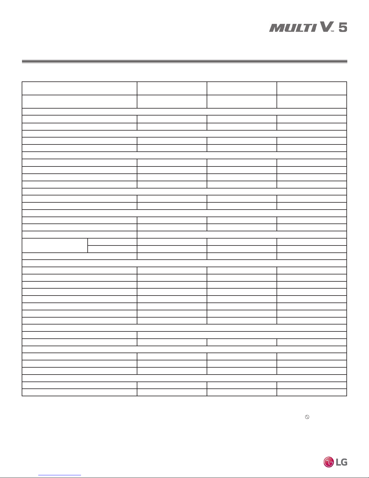
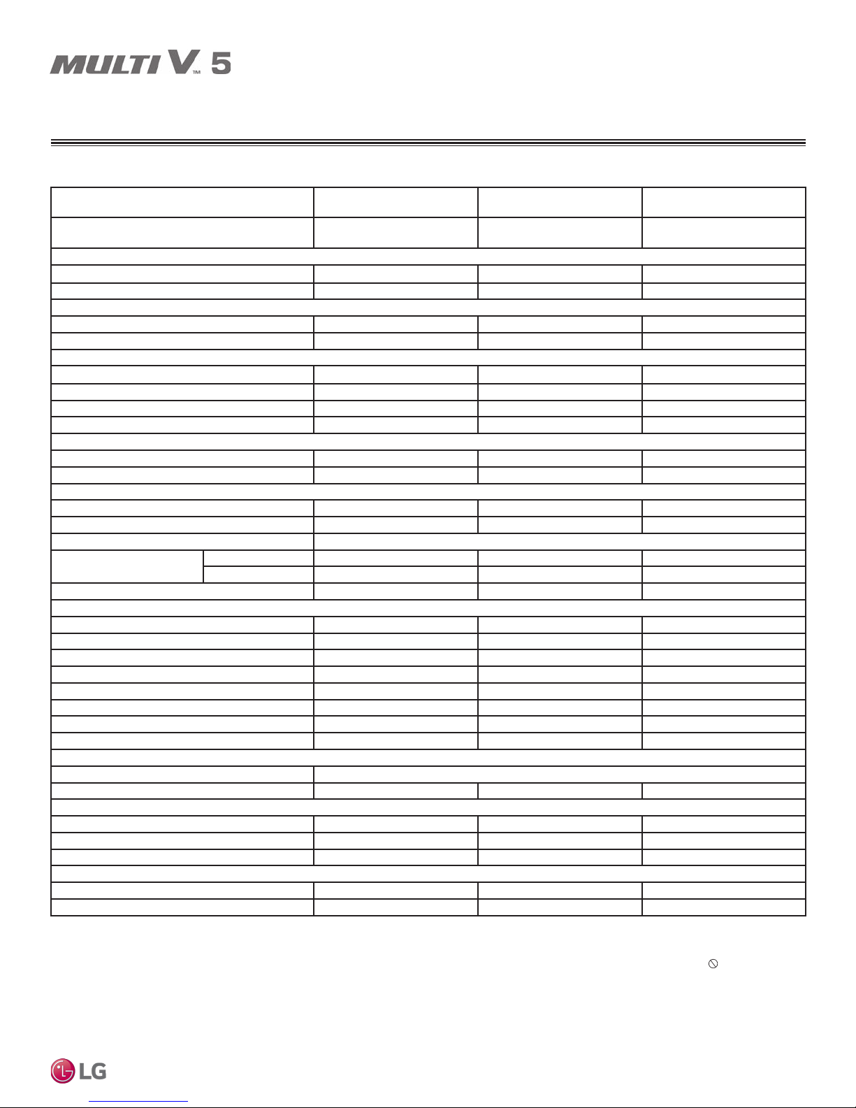
SPECIFICATIONS
208-230V Outdoor Units
Table 4: Dual Frame 208-230V Outdoor Units, continued.
Combination Unit Model Number
Individual Component Model Numbers
Cooling Performance
Nominal Cooling Capacity (Btu/h)
Rated Cooling Capacity (Btu/h)
Heating Performance
Nominal Heating Capacity (Btu/h)
Rated Heating Capacity (Btu/h)
Operating Range
Cooling (°F DB) 5 to 122 5 to 122 5 to 122
Heating (°F WB) -13 to +61 -13 to +61 -13 to +61
Synchronous — Cooling Based (°F DB) 14 to 81 14 to 81 14 to 81
Synchronous — Heating Based (°F WB) 14 to 61 14 to 61 14 to 61
Compressor
Inverter Quantity HSS DC Scroll x 4 HSS DC Scroll x 4 HSS DC Scroll x 4
Oil/Type PVE / FVC68D PVE / FVC68D PVE / FVC68D
Fan (Top Discharge)
Type Propeller (BLDC) Propeller (BLDC) Propeller (BLDC)
Motor Output (kW) x Qty. 0.90 x 2 + 0.90 x 2 0.90 x 2 + 0.90 x 2 0.90 x 2 + 0.90 x 2
Motor/Drive Brushless Digitally Controlled / Direct
Operating Range (RPM)
Maximum Air Volume (CFM) 22,600 22,600 22,600
Unit Data
Refrigerant Type R410A R410A R410A
Refrigerant Control/Location EEV / Indoor Unit EEV / Indoor Unit EEV / Indoor Unit
Factory Charge lbs. of R410A 26.5 + 37.5 26.5 + 37.5 30.9 + 37.5
Max. No. Indoor Units/System
Sound Pressure dB(A)
4
Net Unit Weight (lbs.) 639 + 666 639 + 666 659 + 666
Shipping Weight (lbs.) 666 + 694 666 + 694 688 + 694
MULTI V 5 Outdoor Unit Installation Manual
Communication Cables
5,6
Heat Exchanger
Material and Fin Coating Copper Tube / Aluminum Fin and Black Coated Fin™ / Hydrophilic
Rows / Fins per inch 3 / 17 x 2 3 / 17 x 2 3 / 17 x 2
Piping for Heat Recovery Operation
Liquid Line Connection (in., OD) 1/2 & 5/8 Braze 5/8 & 5/8 Braze 5/8 & 5/8 Braze
Low Pressure Vapor Line Connection (in., OD) 1-1/8 & 1-1/8 Braze 1-1/8 & 1-1/8 Braze 1-1/8 & 1-1/8 Braze
High Pressure Vapor Line Connection (in., OD) 7/8 & 1-1/8 Braze 7/8 & 1-1/8 Braze 1-1/8 & 1-1/8 Braze
Piping for Heat Pump Operation
Liquid Line Connection (in., OD) 1/2 & 5/8 Braze 5/8 & 5/8 Braze 5/8 & 5/8 Braze
Vapor Line Connection (in., OD) 1-1/8 & 1-1/8 Braze 1-1/8 & 1-1/8 Braze 1-1/8 & 1-1/8 Braze
1
Nominal capacity applied with non-ducted indoor units, and is rated 0 ft. above sea level
with 25 ft. of refrigerant line per indoor unit and a 0 ft. level difference between outdoor and
indoor units. All capacities are net with a Combination Ratio between 95–105%.
Nominal cooling capacity rating obtained with air entering the indoor unit at 80ºF dry bulb
(DB) and 67ºF wet bulb (WB) and outdoor ambient conditions of 95ºF dry bulb (DB) and
75ºF wet bulb (WB).
Nominal heating capacity rating obtained with air entering the indoor unit at 70ºF dry bulb
(DB) and 59ºF wet bulb (WB) and outdoor ambient conditions of 47ºF dry bulb (DB) and
43ºF wet bulb (WB).
2
Rated capacity is certied under AHRI Standard 1230. See www.ahrinet.org for information.
3
The System Combination Ratio must be between 50–130%.
12
1
2
1
2
Cooling 0 - 1,150 0 - 1,150 0 - 1,150
Heating 80 - 1,150 80 - 1,150 80 - 1,150
3
7
7
Due to our policy of continuous product innovation, some specifications may change without notification.
©LG Electronics U.S.A., Inc., Englewood Cliffs, NJ. All rights reserved. “LG” is a registered trademark of LG Corp.
ARUM360BTE5
30.0 Ton
ARUM144BTE5 +
ARUM216BTE5
ARUM384BTE5
32.0 Ton
ARUM168BTE5 +
ARUM216BTE5
ARUM192BTE5 +
360,000 384,000 408,000
344,000 366,000 390,000
405,000 432,000 459,000
384,000 410,000 436,000
58 61 64
66.0 66.0 66.0
2 x 18 2 x 18 2 x 18
4
Sound pressure levels are tested in an anechoic chamber under ISO Standard 3745.
5
Communication cable between Master ODU to Slave ODU(s), and Master ODU to IDUs /
HRUs to be 18 AWG, 2-conductor, twisted, stranded, shielded. Ensure the communication
cable shield is properly grounded to the Master ODU chassis only. Do not ground the
ODU to IDUs / HRUs communication cable at any other point. Wiring must comply with all
applicable local and national codes.
6
Power wiring is eld provided, solid or stranded, and must comply with the applicable
local and national codes. See page 19 for detailed electrical data.
7
LG requires that LATS software be used on all projects to ensure correct line sizing.
Designer must verify the shop drawing design against the as built design using LATS.
Contractor must also use LG manufactured Y-Branch and Header Kits only.
ARUM408BTE5
34.0 Ton
ARUM216BTE5
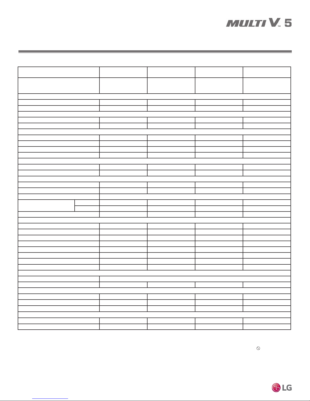
SPECIFICATIONS
208-230V Outdoor Unit
Table 5: Triple Frame 208-230V Outdoor Units.
Combination Unit Model Number
ARUM432BTE5
36.0 Ton
ARUM121BTE5 +
Individual Component Model Numbers
ARUM121BTE5 +
ARUM192BTE5
Cooling Performance
Nominal Cooling Capacity (Btu/h)
Rated Cooling Capacity (Btu/h)
1
2
432,000 456,000 480,000 504,000
412,000 434,000 458,000 480,000
Heating Performance
Nominal Heating Capacity (Btu/h)
Rated Heating Capacity (Btu/h)
1
2
486,000 513,000 540,000 567,000
460,000 488,000 513,000 539,000
Operating Range
Cooling (°F DB) 5 to 122 5 to 122 5 to 122 5 to 122
Heating (°F WB) -13 to +61 -13 to +61 -13 to +61 -13 to +61
Synchronous — Cooling Based (°F DB) 14 to 81 14 to 81 14 to 81 14 to 81
Synchronous — Heating Based (°F WB) 14 to 61 14 to 61 14 to 61 14 to 61
Compressor
Inverter Quantity HSS DC Scroll x 4 HSS DC Scroll x 4 HSS DC Scroll x 5 HSS DC Scroll x 5
Oil/Type PVE / FVC68D PVE / FVC68D PVE / FVC68D PVE / FVC68D
Fan (Top Discharge)
Type Propeller (BLDC) Propeller (BLDC) Propeller (BLDC) Propeller (BLDC)
Motor Output (kW) x Qty. 0.90x2 + 0.90x2 + 0.90x2 0.90x2 + 0.90x2 + 0.90x2 0.90x2 + 0.90x2 + 0.90x2 0.90x2 + 0.90x2 + 0.90x2
Motor/Drive Brushless Digitally Controlled / Direct
Operating Range (RPM)
Cooling 0 - 1,150 0 - 1,150 0 - 1,150 0 - 1,150
Heating 80 - 1,150 80 - 1,150 80 - 1,150 80 - 1,150
Maximum Air Volume (CFM) 33,900 33,900 33,900 33,900
Unit Data
Refrigerant Type R410A R410A R410A R410A
Refrigerant Control/Location EEV / Indoor Unit EEV / Indoor Unit EEV / Indoor Unit EEV / Indoor Unit
Factory Charge lbs. of R410A 23.2 + 23.2 + 30.9 23.2 + 23.2 + 37.5 23.2 + 26.5 + 37.5 23.2 + 26.5 + 37.5
Max. No. Indoor Units/System
Sound Pressure dB(A)
3
4
64 64 64 64
66.0 66.0 67.0 67.0
Net Unit Weight (lbs.) 507 + 507 + 659 507 + 507 + 666 507 + 639 + 666 507 + 639 + 666
Shipping Weight (lbs.) 534 + 534 + 688 534 + 534 + 694 534 + 666 + 694 534 + 666 + 694
Communication Cables
5,6
2 x 18 2 x 18 2 x 18 2 x 18
Heat Exchanger
Material and Fin Coating Copper Tube / Aluminum Fin and Black Coated Fin™ / Hydrophilic
Rows / Fins per inch 2/17 x 2 + 3/17 2 / 17 x 2 + 3 / 17 2 / 17 + 3 / 17 x 2 2 / 17 + 3 / 17 x 2
Piping for Heat Recovery Operation
7
Liquid Line Connection (in., OD) 1/2 & 1/2 & 5/8 Braze 1/2 & 1/2 & 5/8 Braze 1/2 & 1/2 & 5/8 Braze 1/2 & 5/8 & 5/8 Braze
Low Pressure Vapor Line Conn. (in., OD) 1-1/8 & 1-1/8 & 1-1/8 Braze 1-1/8 & 1-1/8 & 1-1/8 Braze 1-1/8 & 1-1/8 & 1-1/8 Braze 1-1/8 & 1-1/8 & 1-1/8 Braze
High Pressure Vapor Line Conn. (in., OD) 3/4 & 3/4 & 1-1/8 Braze 3/4 & 3/4 & 1-1/8 Braze 3/4 & 7/8 & 1-1/8 Braze 3/4 & 7/8 & 1-1/8 Braze
Piping for Heat Pump Operation
7
Liquid Line Connection (in., OD) 1/2 + 1/2 + 5/8 Braze 1/2 & 1/2 & 5/8 Braze 1/2 & 1/2 & 5/8 Braze 1/2 & 5/8 & 5/8 Braze
Vapor Line Connection (in., OD) 1-1/8 & 1-1/8 & 1-1/8 Braze 1-1/8 & 1-1/8 & 1-1/8 Braze 1-1/8 & 1-1/8 & 1-1/8 Braze 1-1/8 & 1-1/8 & 1-1/8 Braze
1
Nominal capacity applied with non-ducted indoor units, and is rated 0 ft. above sea level
with 25 ft. of refrigerant line per indoor unit and a 0 ft. level difference between outdoor and
indoor units. All capacities are net with a Combination Ratio between 95–105%.
Nominal cooling capacity rating obtained with air entering the indoor unit at 80ºF dry bulb
(DB) and 67ºF wet bulb (WB) and outdoor ambient conditions of 95ºF dry bulb (DB) and
75ºF wet bulb (WB).
Nominal heating capacity rating obtained with air entering the indoor unit at 70ºF dry bulb
(DB) and 59ºF wet bulb (WB) and outdoor ambient conditions of 47ºF dry bulb (DB) and
43ºF wet bulb (WB).
2
Rated capacity is certied under AHRI Standard 1230. See www.ahrinet.org for information.
3
The System Combination Ratio must be between 50–130%.
ARUM456BTE5
38.0 Ton
ARUM121BTE5 +
ARUM121BTE5 +
ARUM216BTE5
4
Sound pressure levels are tested in an anechoic chamber under ISO Standard 3745.
5
Communication cable between Master ODU to Slave ODU(s), and Master ODU to IDUs /
HRUs to be 18 AWG, 2-conductor, twisted, stranded, shielded. Ensure the communication
cable shield is properly grounded to the Master ODU chassis only. Do not ground the
ODU to IDUs / HRUs communication cable at any other point. Wiring must comply with all
applicable local and national codes.
6
Power wiring is eld provided, solid or stranded, and must comply with the applicable
local and national codes. See page 19 for detailed electrical data.
7
LG requires that LATS software be used on all projects to ensure correct line sizing.
Designer must verify the shop drawing design against the as built design using LATS.
Contractor must also use LG manufactured Y-Branch and Header Kits only.
ARUM480BTE5
40.0 Ton
ARUM121BTE5 +
ARUM144BTE5 +
ARUM216BTE5
ARUM504BTE5
42.0 Ton
ARUM121BTE5 +
ARUM168BTE5 +
ARUM216BTE5
Product Data
Due to our policy of continuous product innovation, some specifications may change without notification.
©LG Electronics U.S.A., Inc., Englewood Cliffs, NJ. All rights reserved. “LG” is a registered trademark of LG Corp.
13
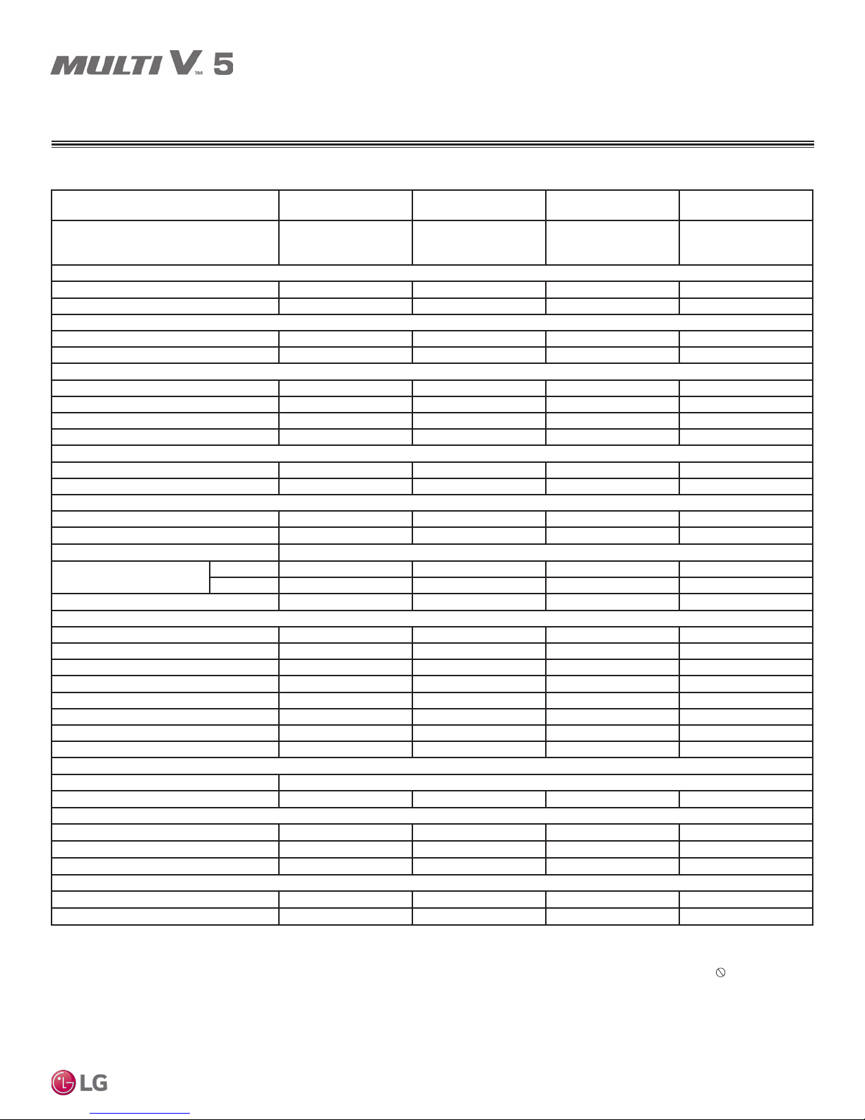
SPECIFICATIONS
460V Outdoor Units
Table 6: Single Frame 460V Outdoor Units.
Unit Model Number
ARUM072DTE5
6.0 Ton
Individual Component Model Numbers - - - -
Cooling Performance
Nominal Cooling Capacity (Btu/h)
Rated Cooling Capacity (Btu/h)
1
2
72,000 96,000 120,000 144,000
69,000 92,000 114,000 138,000
Heating Performance
Nominal Heating Capacity (Btu/h)
Rated Heating Capacity (Btu/h)
1
2
81,000 108,000 135,000 162,000
77,000 103,000 129,000 154,000
Operating Range
Cooling (°F DB) 5 to 122 5 to 122 5 to 122 5 to 122
Heating (°F WB) -13 to +61 -13 to +61 -13 to +61 -13 to +61
Synchronous — Cooling Based (°F DB) 14 to 81 14 to 81 14 to 81 14 to 81
Synchronous — Heating Based (°F WB) 14 to 61 14 to 61 14 to 61 14 to 61
Compressor
Inverter Quantity HSS DC Scroll x 1 HSS DC Scroll x 1 HSS DC Scroll x 1 HSS DC Scroll x 2
Oil/Type PVE / FVC68D PVE / FVC68D PVE / FVC68D PVE / FVC68D
Fan (Top Discharge)
Type Propeller (BLDC) Propeller (BLDC) Propeller (BLDC) Propeller (BLDC)
Motor Output (kW) x Qty. 1.2 x 1 0.9 x 2 0.9 x 2 0.9 x 2
Motor/Drive Brushless Digitally Controlled / Direct
Operating Range (RPM)
Cooling 0 - 1,000 0 - 1,150 0 - 1,150 0 - 1,150
Heating 80 - 1,000 80 - 1,150 80 - 1,150 80 - 1,150
Maximum Air Volume (CFM) 8,470 11,300 11,300 11,300
Unit Data
Refrigerant Type R410A R410A R410A R410A
Refrigerant Control/Location EEV / Indoor Unit EEV / Indoor Unit EEV / Indoor Unit EEV / Indoor Unit
Factory Charge lbs. of R410A 14.3 23.2 23.2 26.5
Max. No. Indoor Units/System
Sound Pressure dB(A)
3
4
13 16 20 24
58.0 58.0 59.0 60.0
Net Unit Weight (lbs.) 430 507 507 639
Shipping Weight (lbs.) 452 534 534 666
Communication Cables
MULTI V 5 Outdoor Unit Installation Manual
Heat Exchanger
5,6
2 x 18 2 x 18 2 x 18 2 x 18
Material and Fin Coating Copper Tube / Aluminum Fin and Black Coated Fin™ / Hydrophilic
Rows / Fins per inch 2 / 17 2 / 17 2 / 17 3 / 17
Piping for Heat Recovery Operation
7
Liquid Line Connection (in., OD) 3/8 Braze 3/8 Braze 1/2 Braze 1/2 Braze
Low Pressure Vapor Line Connection (in., OD) 3/4 Braze 7/8 Braze 1-1/8 Braze 1-1/8 Braze
High Pressure Vapor Line Connection (in., OD) 5/8 Braze 3/4 Braze 3/4 Braze 7/8 Braze
Piping for Heat Pump Operation
7
Liquid Line Connection (in., OD) 3/8 Braze 3/8 Braze 1/2 Braze 1/2 Braze
Vapor Line Connection (in., OD) 3/4 Braze 7/8 Braze 1-1/8 Braze 1-1/8 Braze
1
Nominal capacity applied with non-ducted indoor units, and is rated 0 ft. above sea level
with 25 ft. of refrigerant line per indoor unit and a 0 ft. level difference between outdoor and
indoor units. All capacities are net with a Combination Ratio between 95–105%.
Nominal cooling capacity rating obtained with air entering the indoor unit at 80ºF dry bulb
(DB) and 67ºF wet bulb (WB) and outdoor ambient conditions of 95ºF dry bulb (DB) and
75ºF wet bulb (WB).
Nominal heating capacity rating obtained with air entering the indoor unit at 70ºF dry bulb
(DB) and 59ºF wet bulb (WB) and outdoor ambient conditions of 47ºF dry bulb (DB) and
43ºF wet bulb (WB).
2
Rated capacity is certied under AHRI Standard 1230. See www.ahrinet.org for information.
3
The System Combination Ratio must be between 50–130%.
ARUM096DTE5
8.0 Ton
4
Sound pressure levels are tested in an anechoic chamber under ISO Standard 3745.
5
Communication cable between Master ODU to Slave ODU(s), and Master ODU to IDUs /
HRUs to be 18 AWG, 2-conductor, twisted, stranded, shielded. Ensure the communication
cable shield is properly grounded to the Master ODU chassis only. Do not ground the
ODU to IDUs / HRUs communication cable at any other point. Wiring must comply with all
applicable local and national codes.
6
Power wiring is eld provided, solid or stranded, and must comply with the applicable
local and national codes. See page 20 for detailed electrical data.
7
LG requires that LATS software be used on all projects to ensure correct line sizing.
Designer must verify the shop drawing design against the as built design using LATS.
Contractor must also use LG manufactured Y-Branch and Header Kits only.
ARUM121DTE5
10.0 Ton
ARUM144DTE5
12.0 Ton
14
Due to our policy of continuous product innovation, some specifications may change without notification.
©LG Electronics U.S.A., Inc., Englewood Cliffs, NJ. All rights reserved. “LG” is a registered trademark of LG Corp.
SPECIFICATIONS
460V Outdoor Units
Table 7: Single Frame 460V Outdoor Units, continued.
Unit Model Number
ARUM168DTE5
14.0 Ton
Individual Component Model Numbers - - - -
Cooling Performance
Nominal Cooling Capacity (Btu/h)
Rated Cooling Capacity (Btu/h)
1
2
168,000 192,000 216,000 240,000
160,000 184,000 206,000 222,000
Heating Performance
Nominal Heating Capacity (Btu/h)
Rated Heating Capacity (Btu/h)
1
2
189,000 216,000 243,000 243,000
180,000 206,000 230,000 230,000
Operating Range
Cooling (°F DB) 5 to 122 5 to 122 5 to 122 5 to 122
Heating (°F WB) -13 to +61 -13 to +61 -13 to +61 -13 to +61
Synchronous — Cooling Based (°F DB) 14 to 81 14 to 81 14 to 81 14 to 81
Synchronous — Heating Based (°F WB) 14 to 61 14 to 61 14 to 61 14 to 61
Compressor
Inverter Quantity HSS DC Scroll x 2 HSS DC Scroll x 2 HSS DC Scroll x 2 HSS DC Scroll x 2
Oil/Type PVE / FVC68D PVE / FVC68D PVE / FVC68D PVE / FVC68D
Fan (Top Discharge)
Type Propeller (BLDC) Propeller (BLDC) Propeller (BLDC) Propeller (BLDC)
Motor Output (kW) x Qty. 0.9 x 2 0.9 x 2 0.9 x 2 0.9 x 2
Motor/Drive Brushless Digitally Controlled / Direct
Operating Range (RPM)
Cooling 0 - 1,150 0 - 1,150 0 - 1,150 0 - 1,150
Heating 80 - 1,150 80 - 1,150 80 - 1,150 80 - 1,150
Maximum Air Volume (CFM) 11,300 11,300 11,300 11,300
Unit Data
Refrigerant Type R410A R410A R410A R410A
Refrigerant Control/Location EEV / Indoor Unit EEV / Indoor Unit EEV / Indoor Unit EEV / Indoor Unit
Factory Charge lbs. of R410A 26.5 30.9 37.5 37.5
Max. No. Indoor Units/System
Sound Pressure dB(A)
3
4
29 32 35 39
61.0 62.0 64.0 65.0
Net Unit Weight (lbs.) 639 659 666 666
Shipping Weight (lbs.) 666 688 694 694
Communication Cables
5,6
2 x 18 2 x 18 2 x 18 2 x 18
Heat Exchanger
Material and Fin Coating Copper Tube / Aluminum Fin and Black Coated Fin™ / Hydrophilic
Rows / Fins per inch 3 / 17 3 / 17 3 / 17 3 / 17
Piping for Heat Recovery Operation
7
Liquid Line Connection (in., OD) 5/8 Braze 5/8 Braze 5/8 Braze 5/8 Braze
Low Pressure Vapor Line Connection (in., OD) 1-1/8 Braze 1-1/8 Braze 1-1/8 Braze 1-3/8 Braze
High Pressure Vapor Line Connection (in., OD) 7/8 Braze 1-1/8 Braze 1-1/8 Braze 1-1/8 Braze
Piping for Heat Pump Operation
7
Liquid Line Connection (in., OD) 5/8 Braze 5/8 Braze 5/8 Braze 5/8 Braze
Vapor Line Connection (in., OD) 1-1/8 Braze 1-1/8 Braze 1-1/8 Braze 1-3/8 Braze
1
Nominal capacity applied with non-ducted indoor units, and is rated 0 ft. above sea level
with 25 ft. of refrigerant line per indoor unit and a 0 ft. level difference between outdoor and
indoor units. All capacities are net with a Combination Ratio between 95–105%.
Nominal cooling capacity rating obtained with air entering the indoor unit at 80ºF dry bulb
(DB) and 67ºF wet bulb (WB) and outdoor ambient conditions of 95ºF dry bulb (DB) and
75ºF wet bulb (WB).
Nominal heating capacity rating obtained with air entering the indoor unit at 70ºF dry bulb
(DB) and 59ºF wet bulb (WB) and outdoor ambient conditions of 47ºF dry bulb (DB) and
43ºF wet bulb (WB).
2
Rated capacity is certied under AHRI Standard 1230. See www.ahrinet.org for information.
3
The System Combination Ratio must be between 50–130%.
ARUM192DTE5
16.0 Ton
4
Sound pressure levels are tested in an anechoic chamber under ISO Standard 3745.
5
Communication cable between Master ODU to Slave ODU(s), and Master ODU to IDUs /
HRUs to be 18 AWG, 2-conductor, twisted, stranded, shielded. Ensure the communication
cable shield is properly grounded to the Master ODU chassis only. Do not ground the
ODU to IDUs / HRUs communication cable at any other point. Wiring must comply with all
applicable local and national codes.
6
Power wiring is eld provided, solid or stranded, and must comply with the applicable
local and national codes. See page 20 for detailed electrical data.
7
LG requires that LATS software be used on all projects to ensure correct line sizing.
Designer must verify the shop drawing design against the as built design using LATS.
Contractor must also use LG manufactured Y-Branch and Header Kits only.
ARUM216DTE5
18.0 Ton
ARUM241DTE5
20.0 Ton
Product Data
Due to our policy of continuous product innovation, some specifications may change without notification.
©LG Electronics U.S.A., Inc., Englewood Cliffs, NJ. All rights reserved. “LG” is a registered trademark of LG Corp.
15
SPECIFICATIONS
460V Outdoor Units
Table 8: Dual Frame 460V Outdoor Units.
Combination Unit Model Number
Individual Component Model Numbers
ARUM264DTE5
22.0 Ton
ARUM096DTE5 +
ARUM168DTE5
Cooling Performance
Nominal Cooling Capacity (Btu/h)
Rated Cooling Capacity (Btu/h)
2
1
264,000 288,000 312,000 336,000
252,000 276,000 298,000 320,000
Heating Performance
Nominal Heating Capacity (Btu/h)
Rated Heating Capacity (Btu/h)
1
2
297,000 324,000 351,000 378,000
283,000 309,000 333,000 359,000
Operating Range
Cooling (°F DB) 5 to 122 5 to 122 5 to 122 5 to 122
Heating (°F WB) -13 to +61 -13 to +61 -13 to +61 -13 to +61
Synchronous — Cooling Based (°F DB) 14 to 81 14 to 81 14 to 81 14 to 81
Synchronous — Heating Based (°F WB) 14 to 61 14 to 61 14 to 61 14 to 61
Compressor
Inverter Quantity HSS DC Scroll x 3 HSS DC Scroll x 3 HSS DC Scroll x 3 HSS DC Scroll x 3
Oil/Type PVE / FVC68D PVE / FVC68D PVE / FVC68D PVE / FVC68D
Fan (Top Discharge)
Type Propeller (BLDC) Propeller (BLDC) Propeller (BLDC) Propeller (BLDC)
Motor Output (kW) x Qty. 0.90 x 2 + 0.90 x 2 0.90 x 2 + 0.90 x 2 0.90 x 2 + 0.90 x 2 0.90 x 2 + 0.90 x 2
Motor/Drive Brushless Digitally Controlled / Direct
Operating Range (RPM)
Cooling 0 - 1,150 0 - 1,150 0 - 1,150 0 - 1,150
Heating 80 - 1,150 80 - 1,150 80 - 1,150 80 - 1,150
Maximum Air Volume (CFM) 22,600 22,600 22,600 22,600
Unit Data
Refrigerant Type R410A R410A R410A R410A
Refrigerant Control/Location EEV / Indoor Unit EEV / Indoor Unit EEV / Indoor Unit EEV / Indoor Unit
Factory Charge lbs. of R410A 23.2 + 26.5 23.2 + 30.9 23.2 + 37.5 23.2 + 37.5
Max. No. Indoor Units/System
Sound Pressure dB(A)
3
4
42 45 52 55
63.0 63.0 65.0 65.0
Net Unit Weight (lbs.) 507 + 639 507 + 659 507 + 666 507 + 666
Shipping Weight (lbs.) 534 + 666 534 + 688 534 + 694 534 + 694
Communication Cables
MULTI V 5 Outdoor Unit Installation Manual
Heat Exchanger
5,6
2 x 18 2 x 18 2 x 18 2 x 18
Material and Fin Coating Copper Tube / Aluminum Fin and Black Coated Fin™ / Hydrophilic
Rows / Fins per inch 2 / 17 + 3 / 17 2 / 17 + 3 / 17 2 / 17 + 3 / 17 2 / 17 + 3 / 17
Piping for Heat Recovery Operation
7
Liquid Line Connection (in., OD) 3/8 & 5/8 Braze 3/8 & 5/8 Braze 3/8 & 5/8 Braze 1/2 & 5/8 Braze
Low Pressure Vapor Line Connection (in., OD) 7/8 & 1-1/8 Braze 7/8 & 1-1/8 Braze 7/8 & 1-1/8 Braze 1-1/8 & 1-1/8 Braze
High Pressure Vapor Line Connection (in., OD) 3/4 & 7/8 Braze 3/4 & 1-1/8 Braze 3/4 & 1-1/8 Braze 3/4 & 1-1/8 Braze
Piping for Heat Pump Operation
7
Liquid Line Connection (in., OD) 3/8 & 5/8 Braze 3/8 & 5/8 Braze 3/8 & 5/8 Braze 1/2 & 5/8 Braze
Vapor Line Connection (in., OD) 7/8 & 1-1/8 Braze 7/8 & 1-1/8 Braze 7/8 & 1-1/8 Braze 1-1/8 & 1-1/8 Braze
1
Nominal capacity applied with non-ducted indoor units, and is rated 0 ft. above sea level
with 25 ft. of refrigerant line per indoor unit and a 0 ft. level difference between outdoor and
indoor units. All capacities are net with a Combination Ratio between 95–105%.
Nominal cooling capacity rating obtained with air entering the indoor unit at 80ºF dry bulb
(DB) and 67ºF wet bulb (WB) and outdoor ambient conditions of 95ºF dry bulb (DB) and
75ºF wet bulb (WB).
Nominal heating capacity rating obtained with air entering the indoor unit at 70ºF dry bulb
(DB) and 59ºF wet bulb (WB) and outdoor ambient conditions of 47ºF dry bulb (DB) and
43ºF wet bulb (WB).
2
Rated capacity is certied under AHRI Standard 1230. See www.ahrinet.org for information.
3
The System Combination Ratio must be between 50–130%.
ARUM288DTE5
24.0 Ton
ARUM096DTE5 +
ARUM192DTE5
4
Sound pressure levels are tested in an anechoic chamber under ISO Standard 3745.
5
Communication cable between Master ODU to Slave ODU(s), and Master ODU to IDUs /
HRUs to be 18 AWG, 2-conductor, twisted, stranded, shielded. Ensure the communication
cable shield is properly grounded to the Master ODU chassis only. Do not ground the
ODU to IDUs / HRUs communication cable at any other point. Wiring must comply with all
applicable local and national codes.
6
Power wiring is eld provided, solid or stranded, and must comply with the applicable
local and national codes. See page 20 for detailed electrical data.
7
LG requires that LATS software be used on all projects to ensure correct line sizing.
Designer must verify the shop drawing design against the as built design using LATS.
Contractor must also use LG manufactured Y-Branch and Header Kits only.
ARUM312DTE5
26.0 Ton
ARUM096DTE5 +
ARUM216DTE5
ARUM336DTE5
ARUM121DTE5 +
ARUM216DTE5
28.0 Ton
16
Due to our policy of continuous product innovation, some specifications may change without notification.
©LG Electronics U.S.A., Inc., Englewood Cliffs, NJ. All rights reserved. “LG” is a registered trademark of LG Corp.
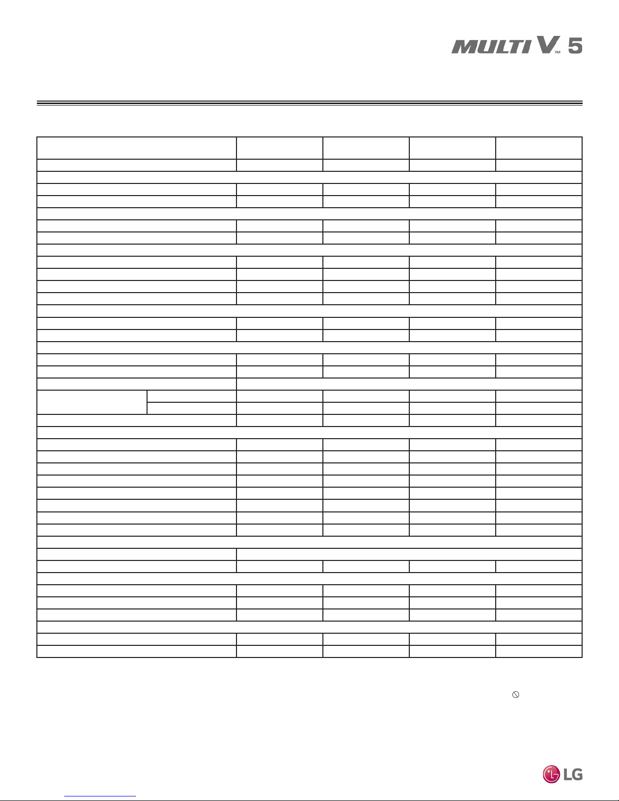
SPECIFICATIONS
460V Outdoor Units
Table 9: Dual Frame 460V Outdoor Units, continued.
Combination Unit Model Number
Individual Component Model Numbers
ARUM360DTE5
30.0 Ton
ARUM144DTE5 +
ARUM216DTE5
Cooling Performance
Nominal Cooling Capacity (Btu/h)
Rated Cooling Capacity (Btu/h)
2
1
360,000 384,000 408,000
344,000 366,000 390,000
Heating Performance
Nominal Heating Capacity (Btu/h)
Rated Heating Capacity (Btu/h)
2
1
405,000 432,000 459,000
384,000 410,000 436,000
Operating Range
Cooling (°F DB) 5 to 122 5 to 122 5 to 122
Heating (°F WB) -13 to +61 -13 to +61 -13 to +61
Synchronous — Cooling Based (°F DB) 14 to 81 14 to 81 14 to 81
Synchronous — Heating Based (°F WB) 14 to 61 14 to 61 14 to 61
Compressor
Inverter Quantity HSS DC Scroll x 4 HSS DC Scroll x 4 HSS DC Scroll x 4
Oil/Type PVE / FVC68D PVE / FVC68D PVE / FVC68D
Fan (Top Discharge)
Type Propeller (BLDC) Propeller (BLDC) Propeller (BLDC)
Motor Output (kW) x Qty. 0.90 x 2 + 0.90 x 2 0.90 x 2 + 0.90 x 2 0.90 x 2 + 0.90 x 2
Motor/Drive Brushless Digitally Controlled / Direct
Operating Range (RPM)
Cooling 0 - 1,150 0 - 1,150 0 - 1,150
Heating 80 - 1,150 80 - 1,150 80 - 1,150
Maximum Air Volume (CFM) 22,600 22,600 22,600
Unit Data
Refrigerant Type R410A R410A R410A
Refrigerant Control/Location EEV / Indoor Unit EEV / Indoor Unit EEV / Indoor Unit
Factory Charge lbs. of R410A 26.5 + 37.5 26.5 + 37.5 30.9 + 37.5
Max. No. Indoor Units/System
Sound Pressure dB(A)
4
3
58 61 64
66.0 66.0 66.0
Net Unit Weight (lbs.) 639 + 666 639 + 666 659 + 666
Shipping Weight (lbs.) 666 + 694 666 + 694 688 + 694
Communication Cables
5,6
2 x 18 2 x 18 2 x 18
Heat Exchanger
Material and Fin Coating Copper Tube / Aluminum Fin and Black Coated Fin™ / Hydrophilic
Rows / Fins per inch 3 / 17 x 2 3 / 17 x 2 3 / 17 x 2
Piping for Heat Recovery Operation
7
Liquid Line Connection (in., OD) 1/2 & 5/8 Braze 5/8 & 5/8 Braze 5/8 & 5/8 Braze
Low Pressure Vapor Line Connection (in., OD) 1-1/8 & 1-1/8 Braze 1-1/8 & 1-1/8 Braze 1-1/8 & 1-1/8 Braze
High Pressure Vapor Line Connection (in., OD) 7/8 & 1-1/8 Braze 7/8 & 1-1/8 Braze 1-1/8 & 1-1/8 Braze
Piping for Heat Pump Operation
7
Liquid Line Connection (in., OD) 1/2 & 5/8 Braze 5/8 & 5/8 Braze 5/8 & 5/8 Braze
Vapor Line Connection (in., OD) 1-1/8 & 1-1/8 Braze 1-1/8 & 1-1/8 Braze 1-1/8 & 1-1/8 Braze
1
Nominal capacity applied with non-ducted indoor units, and is rated 0 ft. above sea level
with 25 ft. of refrigerant line per indoor unit and a 0 ft. level difference between outdoor and
indoor units. All capacities are net with a Combination Ratio between 95–105%.
Nominal cooling capacity rating obtained with air entering the indoor unit at 80ºF dry bulb
(DB) and 67ºF wet bulb (WB) and outdoor ambient conditions of 95ºF dry bulb (DB) and
75ºF wet bulb (WB).
Nominal heating capacity rating obtained with air entering the indoor unit at 70ºF dry bulb
(DB) and 59ºF wet bulb (WB) and outdoor ambient conditions of 47ºF dry bulb (DB) and
43ºF wet bulb (WB).
2
Rated capacity is certied under AHRI Standard 1230. See www.ahrinet.org for information.
3
The System Combination Ratio must be between 50–130%.
4
Sound pressure levels are tested in an anechoic chamber under ISO Standard 3745.
5
Communication cable between Master ODU to Slave ODU(s), and Master ODU to IDUs /
HRUs to be 18 AWG, 2-conductor, twisted, stranded, shielded. Ensure the communication
cable shield is properly grounded to the Master ODU chassis only. Do not ground the
ODU to IDUs / HRUs communication cable at any other point. Wiring must comply with all
applicable local and national codes.
6
Power wiring is eld provided, solid or stranded, and must comply with the applicable
local and national codes. See page 20 for detailed electrical data.
7
LG requires that LATS software be used on all projects to ensure correct line sizing.
Designer must verify the shop drawing design against the as built design using LATS.
Contractor must also use LG manufactured Y-Branch and Header Kits only.
ARUM384DTE5
32.0 Ton
ARUM168DTE5 +
ARUM216DTE5
ARUM408DTE5
34.0 Ton
ARUM192DTE5 +
ARUM216DTE5
Product Data
Due to our policy of continuous product innovation, some specifications may change without notification.
©LG Electronics U.S.A., Inc., Englewood Cliffs, NJ. All rights reserved. “LG” is a registered trademark of LG Corp.
17
SPECIFICATIONS
460V Outdoor Units
Table 10: Triple Frame 460V Outdoor Units.
Combination Unit Model Number
ARUM432DTE5
36.0 Ton
ARUM121DTE5 +
Individual Component Model Numbers
ARUM121DTE5 +
ARUM192DTE5
Cooling Performance
Nominal Cooling Capacity (Btu/h)
Rated Cooling Capacity (Btu/h)
1
2
432,000 456,000 480,000 504,000
412,000 434,000 458,000 480,000
Heating Performance
Nominal Heating Capacity (Btu/h)
Rated Heating Capacity (Btu/h)
1
2
486,000 513,000 540,000 567,000
460,000 488,000 513,000 539,000
Operating Range
Cooling (°F DB) 5 to 122 5 to 122 5 to 122 5 to 122
Heating (°F WB) -13 to +61 -13 to +61 -13 to +61 -13 to +61
Synchronous — Cooling Based (°F DB) 14 to 81 14 to 81 14 to 81 14 to 81
Synchronous — Heating Based (°F WB) 14 to 61 14 to 61 14 to 61 14 to 61
Compressor
Inverter Quantity HSS DC Scroll x 4 HSS DC Scroll x 4 HSS DC Scroll x 5 HSS DC Scroll x 5
Oil/Type PVE / FVC68D PVE / FVC68D PVE / FVC68D PVE / FVC68D
Fan (Top Discharge)
Type Propeller (BLDC) Propeller (BLDC) Propeller (BLDC) Propeller (BLDC)
Motor Output (kW) x Qty. 0.90x2 + 0.90x2 + 0.90x2 0.90x2 + 0.90x2 + 0.90x2 0.90x2 + 0.90x2 + 0.90x2 0.90x2 + 0.90x2 + 0.90x2
Motor/Drive Brushless Digitally Controlled / Direct
Operating Range (RPM)
Cooling 0 - 1,150 0 - 1,150 0 - 1,150 0 - 1,150
Heating 80 - 1,150 80 - 1,150 80 - 1,150 80 - 1,150
Maximum Air Volume (CFM) 33,900 33,900 33,900 33,900
Unit Data
Refrigerant Type R410A R410A R410A R410A
Refrigerant Control/Location EEV / Indoor Unit EEV / Indoor Unit EEV / Indoor Unit EEV / Indoor Unit
Factory Charge lbs. of R410A 23.2 + 23.2 + 30.9 23.2 + 23.2 + 37.5 23.2 + 26.5 + 37.5 23.2 + 26.5 + 37.5
Max. No. Indoor Units/System
Sound Pressure dB(A)
3
4
64 64 64 64
66.0 66.0 67.0 67.0
Net Unit Weight (lbs.) 507 + 507 + 659 507 + 507 + 666 507 + 639 + 666 507 + 639 + 666
Shipping Weight (lbs.) 534 + 534 + 688 534 + 534 + 694 534 + 666 + 694 534 + 666 + 694
Communication Cables
MULTI V 5 Outdoor Unit Installation Manual
5,6
2 x 18 2 x 18 2 x 18 2 x 18
Heat Exchanger
Material and Fin Coating Copper Tube / Aluminum Fin and Black Coated Fin™ / Hydrophilic
Rows / Fins per inch 2/17 x 2 + 3/17 2 / 17 x 2 + 3 / 17 2 / 17 + 3 / 17 x 2 2 / 17 + 3 / 17 x 2
Piping for Heat Recovery Operation
7
Liquid Line Connection (in., OD) 1/2 & 1/2 & 5/8 Braze 1/2 & 1/2 & 5/8 Braze 1/2 & 1/2 & 5/8 Braze 1/2 & 5/8 & 5/8 Braze
Low Pressure Vapor Line Conn. (in., OD) 1-1/8 & 1-1/8 & 1-1/8 Braze 1-1/8 & 1-1/8 & 1-1/8 Braze 1-1/8 & 1-1/8 & 1-1/8 Braze 1-1/8 & 1-1/8 & 1-1/8 Braze
High Pressure Vapor Line Conn. (in., OD) 3/4 & 3/4 & 1-1/8 Braze 3/4 & 3/4 & 1-1/8 Braze 3/4 & 7/8 & 1-1/8 Braze 3/4 & 7/8 & 1-1/8 Braze
Piping for Heat Pump Operation
7
Liquid Line Connection (in., OD) 1/2 & 1/2 & 5/8 Braze 1/2 & 1/2 & 5/8 Braze 1/2 & 1/2 & 5/8 Braze 1/2 & 5/8 & 5/8 Braze
Vapor Line Connection (in., OD) 1-1/8 & 1-1/8 & 1-1/8 Braze 1-1/8 & 1-1/8 & 1-1/8 Braze 1-1/8 & 1-1/8 & 1-1/8 Braze 1-1/8 & 1-1/8 & 1-1/8 Braze
1
Nominal capacity applied with non-ducted indoor units, and is rated 0 ft. above sea level
with 25 ft. of refrigerant line per indoor unit and a 0 ft. level difference between outdoor and
indoor units. All capacities are net with a Combination Ratio between 95–105%.
Nominal cooling capacity rating obtained with air entering the indoor unit at 80ºF dry bulb
(DB) and 67ºF wet bulb (WB) and outdoor ambient conditions of 95ºF dry bulb (DB) and
75ºF wet bulb (WB).
Nominal heating capacity rating obtained with air entering the indoor unit at 70ºF dry bulb
(DB) and 59ºF wet bulb (WB) and outdoor ambient conditions of 47ºF dry bulb (DB) and
43ºF wet bulb (WB).
2
Rated capacity is certied under AHRI Standard 1230. See www.ahrinet.org for information.
3
The System Combination Ratio must be between 50–130%.
ARUM456DTE5
38.0 Ton
ARUM121DTE5 +
ARUM121DTE5 +
ARUM216DTE5
4
Sound pressure levels are tested in an anechoic chamber under ISO Standard 3745.
5
Communication cable between Master ODU to Slave ODU(s), and Master ODU to IDUs /
HRUs to be 18 AWG, 2-conductor, twisted, stranded, shielded. Ensure the communication
cable shield is properly grounded to the Master ODU chassis only. Do not ground the
ODU to IDUs / HRUs communication cable at any other point. Wiring must comply with all
applicable local and national codes.
6
Power wiring is eld provided, solid or stranded, and must comply with the applicable
local and national codes. See page 20 for detailed electrical data.
7
LG requires that LATS software be used on all projects to ensure correct line sizing.
Designer must verify the shop drawing design against the as built design using LATS.
Contractor must also use LG manufactured Y-Branch and Header Kits only.
ARUM480DTE5
40.0 Ton
ARUM121DTE5 +
ARUM144DTE5 +
ARUM216DTE5
ARUM504DTE5
ARUM121DTE5 +
ARUM168DTE5 +
ARUM216DTE5
42.0 Ton
18
Due to our policy of continuous product innovation, some specifications may change without notification.
©LG Electronics U.S.A., Inc., Englewood Cliffs, NJ. All rights reserved. “LG” is a registered trademark of LG Corp.
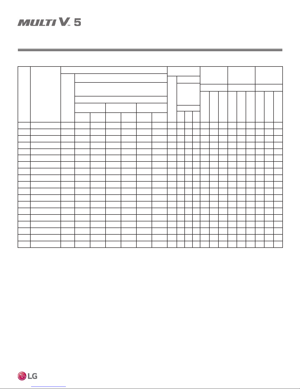
ELECTRICAL DATA
208-230V Outdoor Unit Electrical Data
Table 11: 208-230V, 60Hz, 3-Phase Outdoor Units.
Compressor (Comp.)
Motor Amps
Nom.
Tons
Unit Model
Nos.
Comp.
Qty.
Motor RLA (Ea.)
Frame
1 2 3
Comp. AComp. BComp. AComp. BComp. AComp.
6.0 ARUM072BTE5 1 14.1 - - - - - 1 5.0 - - 22.6 - - 35 - - 35 - -
8.0 ARUM096BTE5 1 16.4 - - - - - 2 8.0 - - 28.5 - - 40 - - 40 - -
10.0 ARUM121BTE5 1 18.3 - - - - - 2 8.0 - - 30.9 - - 40 - - 40 - -
12.0 ARUM144BTE5 2 19.8 18.3 - - - - 2 8.0 - - 51.1 - - 70 - - 70 - -
14.0 ARUM168BTE5 2 21.2 19.1 - - - - 2 8.0 - - 53.6 - - 70 - - 70 - -
16.0 ARUM192BTE5 2 23.3 20.8 - - - - 2 8.0 - - 57.9 - - 80 - - 80 - -
18.0 ARUM216BTE5 2 24.3 21.9 - - - - 2 8.0 - - 60.3 - - 80 - - 80 - -
20.0 ARUM241BTE5 2 25.6 23.2 - - - - 2 8.0 - - 63.2 - - 80 - - 80 - -
22.0 ARUM264BTE5 3 21.2 19.1 16.4 - - - 4 8.0 8.0 - 53.6 28.5 - 70 40 - 70 40 -
24.0 ARUM288BTE5 3 23.3 20.8 16.4 - - - 4 8.0 8.0 - 57.9 28.5 - 80 40 - 80 40 -
26.0 ARUM312BTE5 3 24.3 21.9 16.4 - - - 4 8.0 8.0 - 60.3 28.5 - 80 40 - 80 40 -
28.0 ARUM336BTE5 3 24.3 21.9 18.3 - - - 4 8.0 8.0 - 60.3 30.9 - 80 40 - 80 40 -
30.0 ARUM360BTE5 4 24.3 21.9 19.8 18.3 - - 4 8.0 8.0 - 60.3 51.1 - 80 70 - 80 70 -
32.0 ARUM384BTE5 4 24.3 21.9 21.2 19.1 - - 4 8.0 8.0 - 60.3 53.6 - 80 70 - 80 70 -
34.0 ARUM408BTE5 4 24.3 21.9 23.3 20.8 - - 4 8.0 8.0 - 60.3 57.9 - 80 80 - 80 80 -
36.0 ARUM432BTE5 4 23.3 20.8 18.3 - 18.3 - 6 8.0 8.0 8.0 57.9 30.9 30.9 80
38.0 ARUM456BTE5 4 24.3 21.9 18.3 - 18.3 - 6 8.0 8.0 8.0 60.3 30.9 30.9 80 40 40 80 40 40
40.0 ARUM480BTE5 5 24.3 21.9 19.8 18.3 18.3 - 6 8.0 8.0 8.0 60.3 51.1 30.9 80 70 40 80 70 40
42.0 ARUM504BTE5 5 24.3 21.9 21.2 19.1 18.3 - 6 8.0 8.0 8.0 60.3 53.6 30.9 80 70 40 80 70 40
For component model nos. see the specication tables on p. 9-13.
Voltage tolerance is 187V to 253V.
Maximum allowable voltage unbalance is 2%.
MCA = Minimum Circuit Ampacity.
Maximum Overcurrent Protection (MOCP) is calculated as follows: (Largest motor FLA x
2.25) + (Sum of other motor FLA) rounded down to the nearest standard fuse size. RFA =
Recommended Fuse Amps.
*SCCR rating: 5kA RMS Symmetrical.
Condenser Fan
Fan
Qty.
B
Motor(s)
Amps
FLA (Ea.)
Frame
1 2 3
MCA MOCP RFA
Frame Frame Frame
1 2 3 1 2 3 1 2 3
40 40 80 40 40
Product Data
Due to our policy of continuous product innovation, some specifications may change without notification.
©LG Electronics U.S.A., Inc., Englewood Cliffs, NJ. All rights reserved. “LG” is a registered trademark of LG Corp.
19
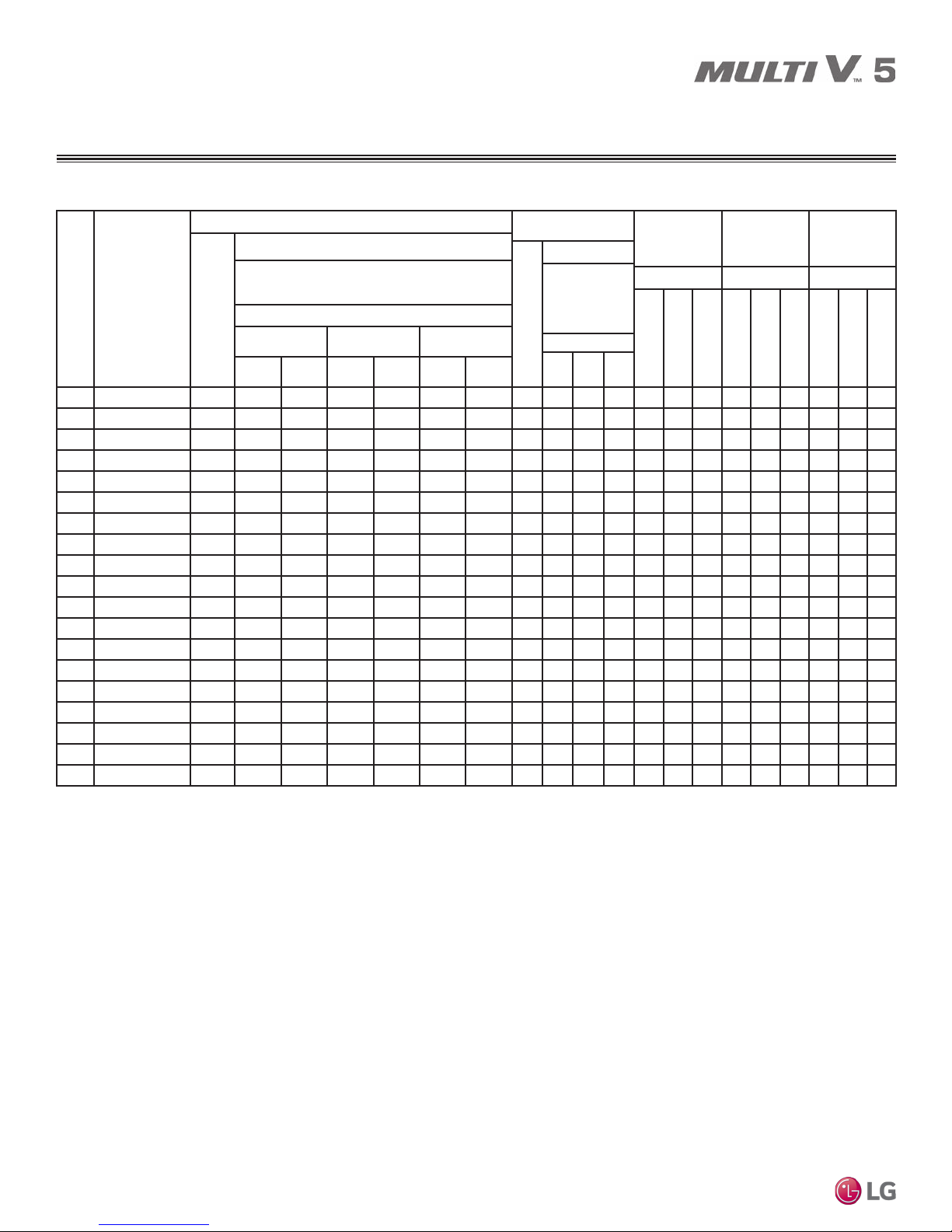
ELECTRICAL DATA
460V Outdoor Unit Electrical Data
Table 12: 460V, 60Hz, 3-Phase Outdoor Units.
Fan
Qty.
B
Condenser Fan
Motor(s)
Amps
FLA (Ea.)
Frame
1 2 3
MCA MOCP RFA
Frame Frame Frame
1 2 3 1 2 3 1 2 3
25 25 50 25 25
Compressor (Comp.)
Motor Amps
Nom.
Tons
Unit Model
Nos.
Comp.
Qty.
Motor RLA (Ea.)
Frame
1 2 3
Comp. AComp. BComp. AComp. BComp. AComp.
6.0 ARUM072DTE5 1 7.8 - - - - - 1 3.0 - - 12.8 - - 20 - - 20 - -
8.0 ARUM096DTE5 1 9.1 - - - - - 2 5.0 - - 16.4 - - 25 - - 25 - -
10.0 ARUM121DTE5 1 10.7 - - - - - 2 5.0 - - 18.4 - - 25 - - 25 - -
12.0 ARUM144DTE5 2 10.3 8.5 - - - - 2 5.0 - - 26.4 - - 35 - - 35 - -
14.0 ARUM168DTE5 2 11.4 9.2 - - - - 2 5.0 - - 28.5 - - 35 - - 35 - -
16.0 ARUM192DTE5 2 14.8 12.2 - - - - 2 5.0 - - 35.7 - - 50 - - 50 - -
18.0 ARUM216DTE5 2 15.5 13.9 - - - - 2 5.0 - - 38.3 - - 50 - - 50 - -
20.0 ARUM241DTE5 2 16.9 15.3 - - - - 2 5.0 - - 41.4 - - 50 - - 50 - -
22.0 ARUM264DTE5 3 11.4 9.2 9.1 - - - 4 5.0 5.0 - 28.5 16.4 - 35 25 - 35 25 -
24.0 ARUM288DTE5 3 14.8 12.2 9.1 - - - 4 5.0 5.0 - 35.7 16.4 - 50 25 - 50 25 -
26.0 ARUM312DTE5 3 15.5 13.9 9.1 - - - 4 5.0 5.0 - 38.3 16.4 - 50 25 - 50 25 -
28.0 ARUM336DTE5 3 15.5 13.9 10.7 - - - 4 5.0 5.0 - 38.3 18.4 - 50 25 - 50 25 -
30.0 ARUM360DTE5 4 15.5 13.9 10.3 8.5 - - 4 5.0 5.0 - 38.3 26.4 - 50 35 - 50 35 -
32.0 ARUM384DTE5 4 15.5 13.9 11.4 9.2 - - 4 5.0 5.0 - 38.3 28.5 - 50 35 - 50 35 -
34.0 ARUM408DTE5 4 15.5 13.9 14.8 12.2 - - 4 5.0 5.0 - 38.3 35.7 - 50 50 - 50 50 -
36.0 ARUM432DTE5 4 14.8 12.2 10.7 - 10.7 - 6 5.0 5.0 5.0 35.7 18.4 18.4 50
38.0 ARUM456DTE5 4 15.5 13.9 10.7 - 10.7 - 6 5.0 5.0 5.0 38.3 18.4 18.4 50 25 25 50 25 25
40.0 ARUM480DTE5 5 15.5 13.9 10.3 8.5 10.7 - 6 5.0 5.0 5.0 38.3 26.4 18.4 50 35 25 50 35 25
42.0 ARUM504DTE5 5 15.5 13.9 11.4 9.2 10.7 - 6 5.0 5.0 5.0 38.3 28.5 18.4 50 35 25 50 35 25
For component model nos. see the specication tables on p. 14-18.
Voltage tolerance is 414V to 528V.
MULTI V 5 Outdoor Unit Installation Manual
Maximum allowable voltage unbalance is 2%.
MCA = Minimum Circuit Ampacity.
Maximum Overcurrent Protection (MOCP) is calculated as follows: (Largest motor FLA x
2.25) + (Sum of other motor FLA) rounded down to the nearest standard fuse size. RFA =
Recommended Fuse Amps.
*SCCR rating: 5kA RMS Symmetrical.
20
Due to our policy of continuous product innovation, some specifications may change without notification.
©LG Electronics U.S.A., Inc., Englewood Cliffs, NJ. All rights reserved. “LG” is a registered trademark of LG Corp.
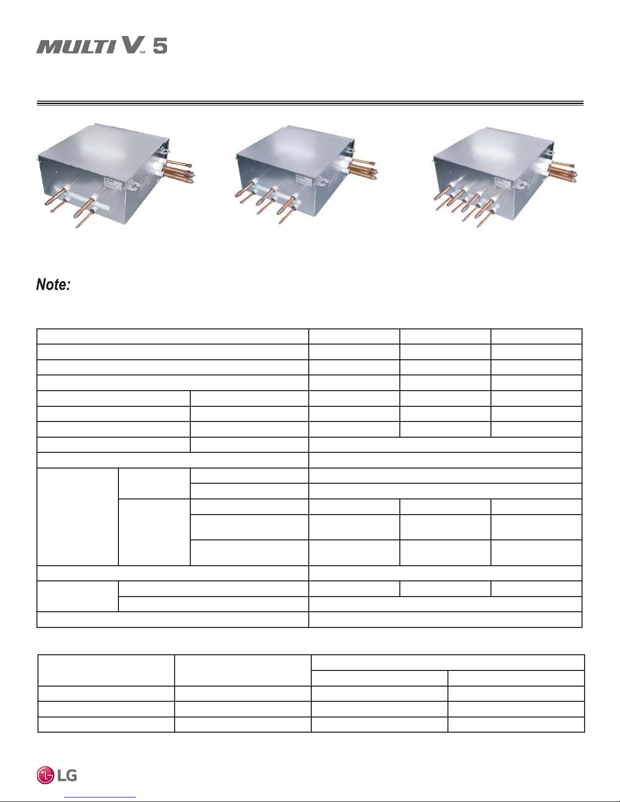
SPECIFICATIONS / ELECTRICAL DATA
Heat Recovery Units
Two-Port Heat Recovery Unit. Three-Port Heat Recovery Unit.
Heat recovery units can only be used with LG systems piped for heat recovery operation.
Table 13: Heat Recovery Unit Specications.
Model PRHR022A PRHR032A PRHR042A
Number of Ports 2 3 4
Max. Connectible No. of Indoor Units 16 24 32
Max. Connectible No. of Indoor Units on each port 8 8 8
Max. Port Capacity (each port) Btu/h 54,000 54,000 54,000
Max. Unit Capacity (sum of ports) Btu/h 192,000 192,000 192,000
Net Weight lbs. 40 45 49
Dimensions (W x H x D) inches 17-7/8 x 8-5/8 x 18-15/16
Casing Galvanized steel plate
To Indoor
Units
Connecting
Pipes
Insulation Material Polyethylene
Current
Power Supply 1Ø, 208-230V, 60Hz
To Outdoor
Units
Minimum Circuit Amps (MCA) 0.1 0.15 0.2
Maximum Fuse Amps (MFA) 15
Liquid Pipe (inches) 3/8
Vapor Pipe (inches) 5/8
Liquid (inches) 3/8 1/2 5/8
Low-pressure Vapor
(inches)
High-pressure Vapor
(inches)
7/8 1-1/8 1-1/8
3/4 7/8 7/8
Four-Port Heat Recovery Unit.
Product Data
Table 14: Heat Recovery Unit Electrical Data.
Unit Model No. V / Hz / Ph
PRHR022A 208-230 / 60 / 1 0.026 0.026
PRHR032A 208-230 / 60 / 1 0.033 0.033
PRHR042A 208-230 / 60 / 1 0.040 0.040
Due to our policy of continuous product innovation, some specifications may change without notification.
©LG Electronics U.S.A., Inc., Englewood Cliffs, NJ. All rights reserved. “LG” is a registered trademark of LG Corp.
Input (kW)
Cooling Heating
21
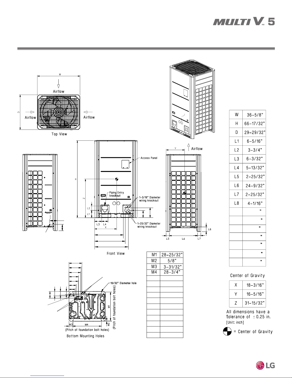
OUTDOOR UNIT DIMENSIONS
ARUM072BTE5 / DTE5
L9
L10
7/8” Diameter Leak Test Hole
Left Side View
L13
L14
L15
MULTI V 5 Outdoor Unit Installation Manual
M5
M6
Power Cord Routing Hole
(Bottom); two (2) - ø2”
Piping Routing Holes (Bottom);
two - ø2-5/8”, ø2-1/8”
M12
M13
M14
M7
M8
M9
M10
M11
M15
Two (2) 7/8” Diameter Wire
Routing Holes (Bottom)
L12
L11
M5
M6
M7
M8
M9
M10
M11
M12
M13
M14
M15
Right Side View
13 – 1/8”
12 – 5/16”
11 – 3/4”
9 – 11/16”
9 – 5/16”
7 – 5/16”
6 – 3/16”
6 – 13/16”
4 – 1/2”
3 – 11/16”
3”
L9
L10
L11
L12
L13
L14
L15
6 – 1/2
5 – 9/16
8 – 5/8
6 – 7/16
24 – 5/8
26 – 7/16
29 – 3/16
22
Due to our policy of continuous product innovation, some specifications may change without notification.
©LG Electronics U.S.A., Inc., Englewood Cliffs, NJ. All rights reserved. “LG” is a registered trademark of LG Corp.
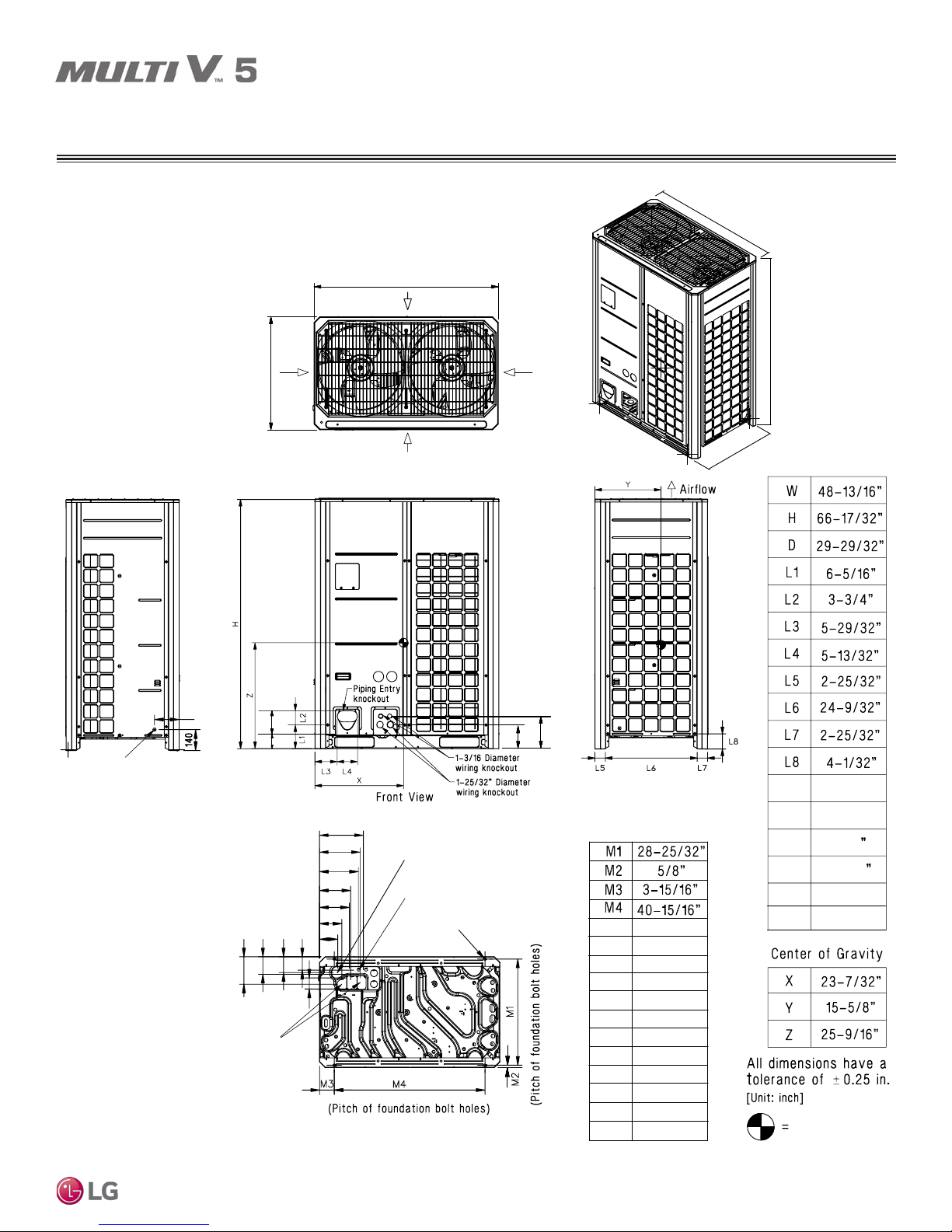
168BTE5 / DTE5, 192BTE5 / DTE5, 216BTE5 / DTE5, 241BTE5 / DTE5
Note: Please refer to multi-frame
placement information and piping
rules in the Multi V 5 Engineering
Manual and the Multi V 5 Installation
Manual. Minimum spacing
between frames is 2-3/4 inches.
OUTDOOR UNIT DIMENSIONS
ARUM096BTE5 / DTE5, 121BTE5 / DTE5, 144BTE5 / DTE5,
W
W
Airflow
H
D
Airflow
Airflow
Airflow
Top View
D
7/8” Diameter Leak Test Hole
Left Side View
Product Data
L9
L10
L13
L14
M15
M14
M13
M12
Piping
Routing
Holes (Bottom);
two - ø2-5/8,”
ø2-1/8”
M5
Power Cord Routing Hole
M6
(Bottom); two (2) - ø2”
M7
M8
M9
M10
M11
M16
Bottom Mounting Holes
L12
Two (2) 7/8” Diameter Wire
Routing Holes (Bottom)
19/32” Dameter Hole
L11
Right Side View
M5
11 – 15/16”
M6
11 – 1/16”
10 – 1/2”
M7
M8
8 – 7/16”
M9
8 – 1/8”
M10
6 – 1/16”
M11
4 – 15/16”
M12
7 – 1/2”
4 – 13/16”
M13
4 – 5/16”
M14
M15
3 – 5/8”
M16
L9
L10
L11
L12
L13
L14
3”
6 – 1/2”
5 – 9/16”
8 – 5/8
6 – 7/16
9 – 15/16”
3 – 5/8”
Center of Gravity
Due to our policy of continuous product innovation, some specifications may change without notification.
©LG Electronics U.S.A., Inc., Englewood Cliffs, NJ. All rights reserved. “LG” is a registered trademark of LG Corp.
23
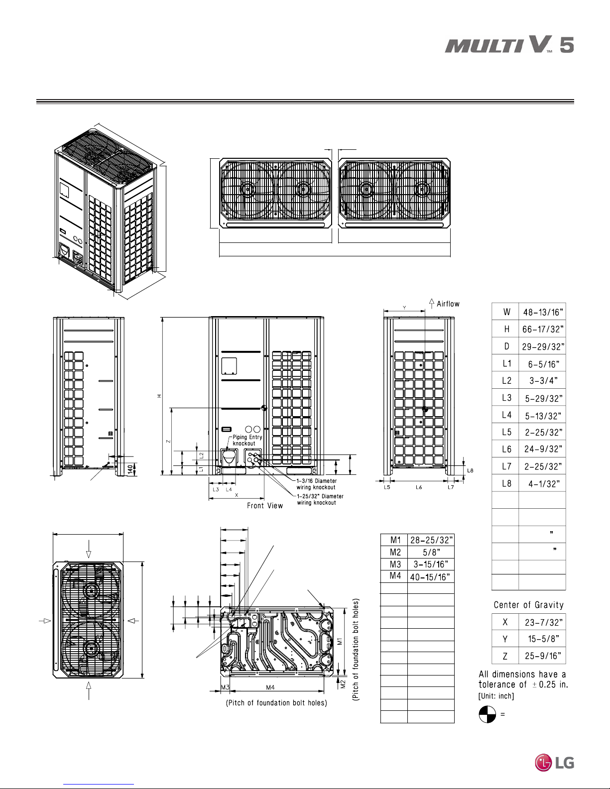
OUTDOOR UNIT DIMENSIONS
M5
M8
M7
M6
M9
M10
M11
M12
M13
M14
M15
11 – 15/16”
11 – 1/16”
10 – 1/2”
8 – 7/16”
8 – 1/8”
6 – 1/16”
4 – 15/16”
7 – 1/2”
4 – 13/16”
4 – 5/16”
3”
L9
L10
7/8” Diameter Leak Test Hole
Left Side View
L9
L10
L11
L12
L13
L14
6 – 1/2”
5 – 9/16”
L11
L12
8 – 5/8
6 – 7/16
9 – 15/16”
L13
L14
3 – 5/8”
Right Side View
Two (2) 7/8” Diameter Wire
Routing Holes (Bottom)
M5
M6
M7
M8
M9
M10
M11
M12
M13
M15
M14
M16
Power Cord Routing Hole
(Bottom); two (2) - ø2”
Holes (Bottom);
two - ø2-5/8,”
ø2-1/8”
M16
3 – 5/8”
Piping
Routing
Center of Gravity
19/32” Dameter Hole
Airflow
Airflow
Top View
Bottom Mounting Holes
Airflow
D
W
Airflow
1 (min)
W W
D
D
W
H
Typical Dual Frame Configuration
Note: Please refer to multi-frame placement information and piping rules in the Multi V 5 Engineering
Manual and the Multi V 5 Installation Manual. Minimum spacing between frames is 2-3/4 inches.
97-5/8 (min)
ARUM264BTE5 / DTE5, 288BTE5 / DTE5, 312BTE5 / DTE5, 336BTE5 / DTE5,
360BTE5 / DTE5, 384BTE5 / DTE5, 408BTE5 / DTE5
MULTI V 5 Outdoor Unit Installation Manual
24
Due to our policy of continuous product innovation, some specifications may change without notification.
©LG Electronics U.S.A., Inc., Englewood Cliffs, NJ. All rights reserved. “LG” is a registered trademark of LG Corp.
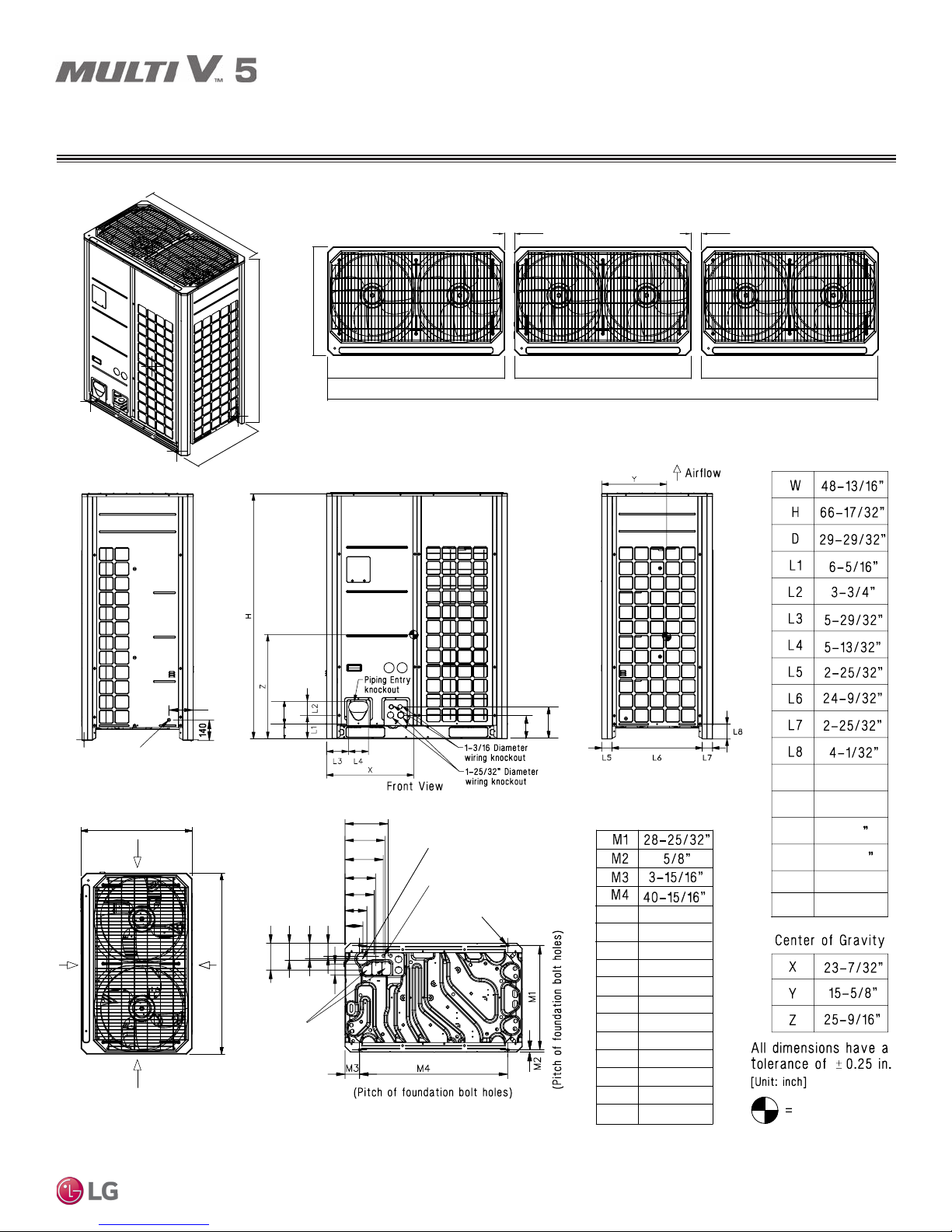
OUTDOOR UNIT DIMENSIONS
ARUM432BTE5 / DTE5, 456BTE5 / DTE5, 480BTE5 / DTE5, 504BTE5 / DTE5
W
Typical Triple Frame Configuration
1 (min) 1 (min)
D
H
W W W
146-7/16 (min)
Note: Please refer to multi-frame placement information and piping rules in the Multi V 5 Engineering
Manual and the Multi V 5 Installation Manual. Minimum spacing between frames is 2-3/4 inches.
D
Product Data
7/8” Diameter Leak Test Hole
Left Side View
Airflow
Airflow
Top View
D
Airflow
L9
Airflow
L10
W
L13
L14
M15
M14
M13
M12
Piping
Routing
Holes (Bottom);
two - ø2-5/8,”
ø2-1/8”
M5
Power Cord Routing Hole
M6
(Bottom); two (2) - ø2”
M7
M8
M9
M10
M11
M16
Bottom Mounting Holes
L12
Two (2) 7/8” Diameter Wire
Routing Holes (Bottom)
19/32” Dameter Hole
L11
Right Side View
M5
11 – 15/16”
M6
11 – 1/16”
10 – 1/2”
M7
M8
8 – 7/16”
M9
8 – 1/8”
M10
6 – 1/16”
M11
4 – 15/16”
M12
7 – 1/2”
4 – 13/16”
M13
4 – 5/16”
M14
M15
3 – 5/8”
M16
L9
L10
L11
L12
L13
L14
3”
6 – 1/2”
5 – 9/16”
8 – 5/8
6 – 7/16
9 – 15/16”
3 – 5/8”
Center of Gravity
Due to our policy of continuous product innovation, some specifications may change without notification.
©LG Electronics U.S.A., Inc., Englewood Cliffs, NJ. All rights reserved. “LG” is a registered trademark of LG Corp.
25
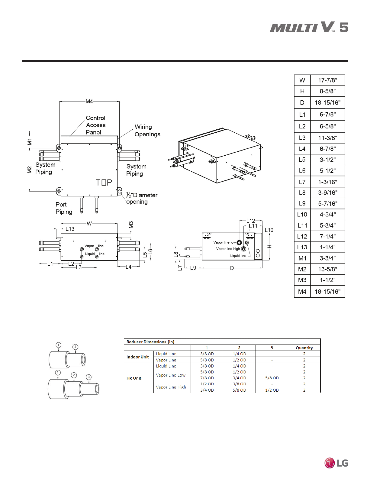
HEAT RECOVERY UNIT DIMENSIONS
PRHR022A
MULTI V 5 Outdoor Unit Installation Manual
26
Due to our policy of continuous product innovation, some specifications may change without notification.
©LG Electronics U.S.A., Inc., Englewood Cliffs, NJ. All rights reserved. “LG” is a registered trademark of LG Corp.
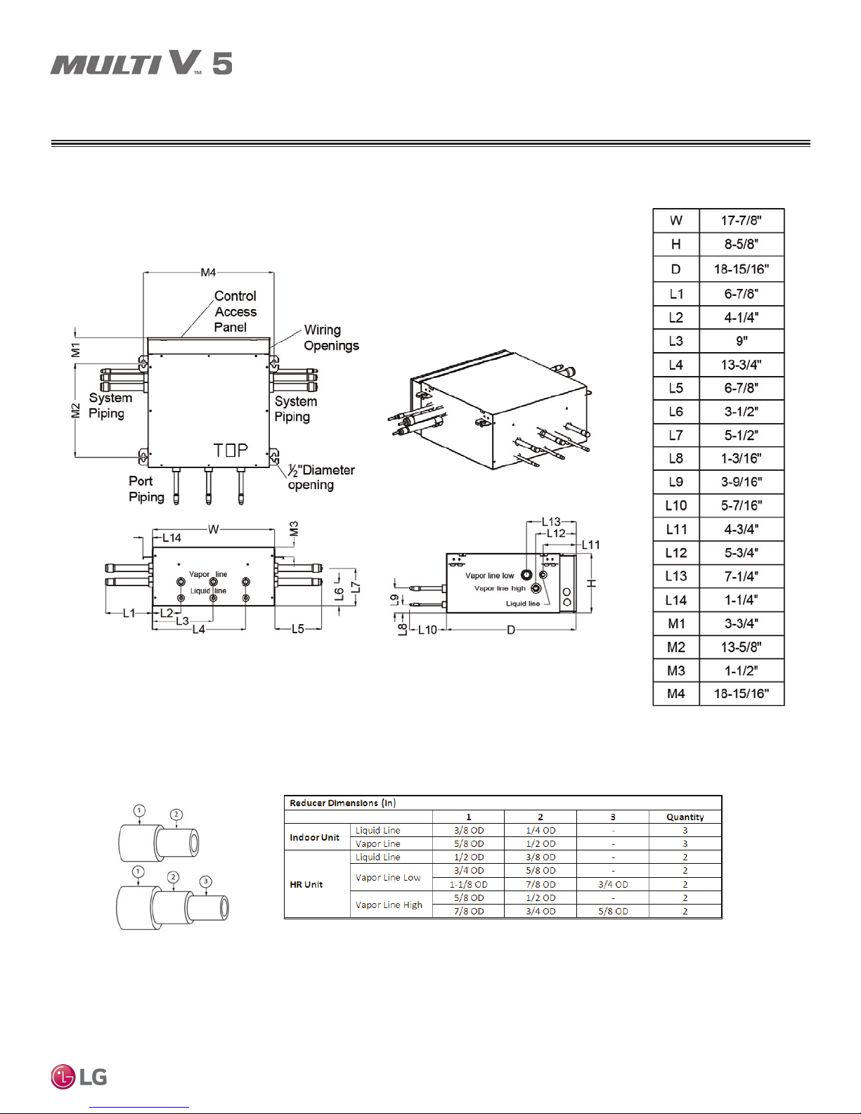
HEAT RECOVERY UNIT DIMENSIONS
PRHR032A
Product Data
Due to our policy of continuous product innovation, some specifications may change without notification.
©LG Electronics U.S.A., Inc., Englewood Cliffs, NJ. All rights reserved. “LG” is a registered trademark of LG Corp.
27
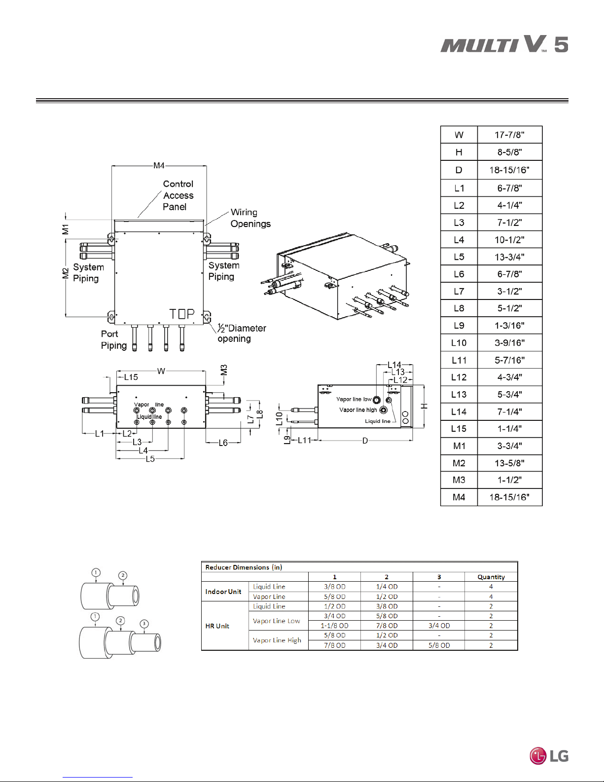
HEAT RECOVERY UNIT DIMENSIONS
PRHR042A
MULTI V 5 Outdoor Unit Installation Manual
28
Due to our policy of continuous product innovation, some specifications may change without notification.
©LG Electronics U.S.A., Inc., Englewood Cliffs, NJ. All rights reserved. “LG” is a registered trademark of LG Corp.
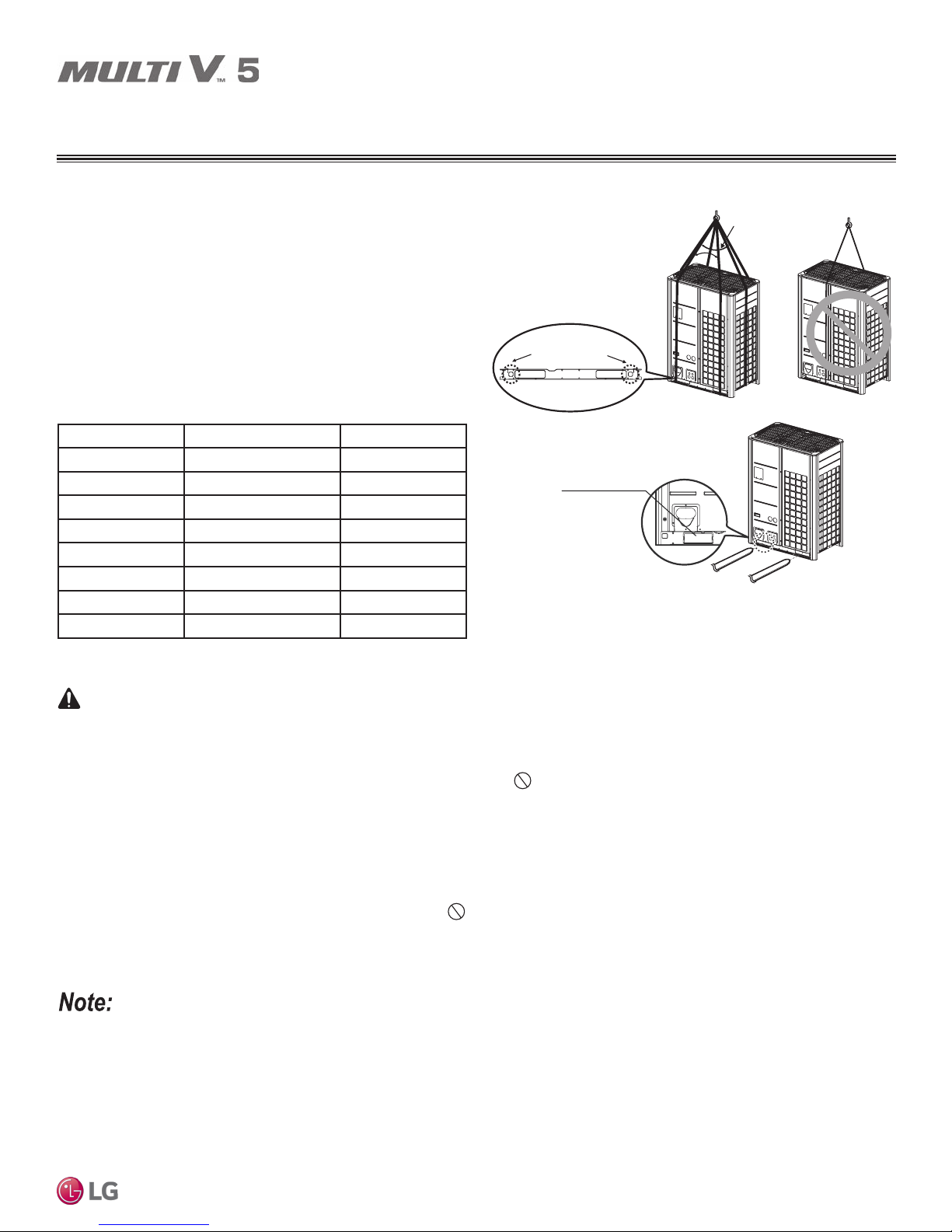
WARNING
TRANSPORTING / LIFTING
Transporting / Lifting the Outdoor
Unit
• When lifting the unit, use lifting straps and place around the unit as
shown.
• Always lift the unit using properly sized lifting straps rated to carry
the unit weight.
• Ensure the straps are long enough to maintain a maximum of a
40° angle as shown at “A”.
Table 15: Multi V 5 Shipping and Net Weights.
Capacity (ton) Shipping Weight (lbs.) Net Weight (lbs.)
6 452 430
8 534 507
10 534 507
12 666 639
14 666 639
16 688 659
18 694 666
20 694 666
Transporting / Lifting the Outdoor Unit.
A
A
Access holes for transportation ropes
A: ≤40°
Access Hole for Forklift
Installation
• Use appropriate moving equipment to transport each frame; ensure the equipment is capable of supporting the weights listed above. If the
equipment is not properly secured, it may result in an accident that causes physical injury or death.
• Wear protective gloves when handling equipment. Sharp edges may cause personal injury.
• Some products include polypropylene bands around the unit for packaging.
risk of the product falling and causing physical injury.
• Tear apart and throw away plastic packaging bags so that children may not play with them and risk suffocation and death.
• Consider the unit’s center of gravity is before lifting. Hoist the unit with the center of gravity centered among the lifting straps. There is a risk
of the product falling and causing physical injury.
• Lift the outdoor unit from the base at specified locations. Support the outdoor unit at a minimum of six (6) points to avoid slippage from the
rigging apparatus, and use a minimum of three (3) lifting straps. There is a risk of the product falling and causing physical injury.
• Use caution when using forklift to transport an unpackaged unit. Do not drop the unit when carrying it with a forklift. There is a risk of the
product falling and causing physical injury.
Place a protective cloth or other soft material at the locations where the casing comes in contact with the lifting straps to prevent damage to painted
surfaces.
Do not use polypropylene bands to lift the unit. There is a
Due to our policy of continuous product innovation, some specications may change without notication.
©LG Electronics U.S.A., Inc., Englewood Cliffs, NJ. All rights reserved. “LG” is a registered trademark of LG Corp.
29
PLACEMENT CONSIDERATIONS
CAUTION
DANGER
CAUTION
Selecting the Best Location for the Outdoor Unit(s)
Selecting the Best Location for the Outdoor Unit(s)
• Do not install the unit in an area where combustible gas may generate, flow, stagnate, or leak. These conditions can cause a fire, result-
ing in bodily injury or death.
•
Do not install the unit in a location where acidic solution and spray (sulfur) are often used as it can cause bodily injury or death.
• Do not use the unit in environments where oil, steam, or sulfuric gas are present as it can cause bodily injury or death.
When deciding on a location to place the outdoor unit, be sure to choose an area where run-off from defrost will not accumulate and freeze on
sidewalks or driveways, which may create unsafe conditions. Properly install and insulate any drain hoses to prevent the hose from freezing,
cracking, leaking, and causing unsafe conditions from frozen condensate.
Install a fence to prevent vermin from crawling into the unit or unauthorized individuals from accessing it. Follow the placement guidelines set forth in
“Clearance Requirements”.
Select a location for installing the outdoor unit that will meet the following conditions:
• Where there is enough strength to bear the weight of the outdoor unit.
• A location that allows for optimum air flow and is easily accessible for inspection, maintenance, and service.
• Where piping between the outdoor unit and indoor unit(s) / heat recovery units are within allowable limits.
• Include space for drainage to ensure condensate flows properly out of the unit when it is in heating mode. Avoid placing the outdoor unit in
a low-lying area where water could accumulate.
• If the outdoor unit is installed in a highly humid environment (near an ocean, lake, etc.), ensure that the site is well-ventilated and has a lot
of natural light (Example: Install on a rooftop).
Don’ts
• Where it will be subjected to direct thermal radiation from other heat sources, or an area that would expose the outdoor unit to heat or
steam like discharge from boiler stacks, chimneys, steam relief ports, other air conditioning units, kitchen vents, plumbing vents, and other
sources of extreme temperatures.
• Where high-frequency electrical noise / electromagnetic waves will affect operation.
• Where operating sound from the unit will disturb inhabitants of surrounding buildings.
• Where the unit will be exposed to direct, strong winds.
• Where the discharge of one outdoor unit will blow into the inlet side of an adjacent unit (when installing multiple outdoor units).
Planning for Snow and Ice
MULTI V 5 Outdoor Unit Installation Manual
To ensure the outdoor unit operates properly, certain measures are required in locations where there is a possibility of heavy snowfall or
severe wind chill or cold:
1. Prepare for severe winter wind chills and heavy snowfall, even in areas of the country where these are unusual phenomena.
2. Position the outdoor unit so that its airflow fans are not buried by direct, heavy snowfall. If snow piles up and blocks the airflow, the
system may malfunction.
3. Remove any snow that has accumulated four (4) inches or more on the top of the outdoor unit.
4. In climates that may experience significant snow buildup, mount the outdoor unit on a raised, field-provided platform or stand. The raised
support platform must be high enough to allow the unit to remain above possible snow drifts, and must be higher than the maximum anticipated snowfall for the location.
5. Design the mounting base to prevent snow accumulation on the platform in front or back of the unit frame.
6. Provide a field fabricated snow protection hood to keep snow and ice and/or drifting snow from accumulating on the coil surfaces.
7. Install a hail guard kit and air guide accessories (sold separately) to prevent snow or rain from accumulating on the fan inlet / outlet guards.
8. Consider tie-down requirements in case of high winds or where required by local codes.
When deciding on a location to place the outdoor unit, be sure to choose an area where run-off from defrost will not accumulate and freeze on
sidewalks or driveways, which may create unsafe conditions. Properly install and insulate any drain hoses to prevent the hose from freezing,
cracking, leaking, and causing unsafe conditions from frozen condensate.
30
Due to our policy of continuous product innovation, some specications may change without notication.
©LG Electronics U.S.A., Inc., Englewood Cliffs, NJ. All rights reserved. “LG” is a registered trademark of LG Corp.
 Loading...