

Page 1

INSTALLATION MANUAL
AIR
CONDITIONER
ENGLISH
Please read this installation manual completely before installing the product.
Installation work must be performed in accordance with the national wiring
standards by authorized personnel only.
Please retain this installation manual for future reference after reading it
thoroughly.
Ceiling Concealed Duct
Original instruction
MFL68821903
Rev.01_050819
Copyright © 2016 - 2019 LG Electronics Inc. All Rights Reserved.
www.lg.com
Page 2
TABLE OF CONTENTS
TABLE OF CONTENTS
3 Features
4 Safety Precautions
7 Installation
7 Selection of the best location
8 Ceiling dimension and hanging bolt location
9 Indoor Unit Installation
9 Wiring Connection
10 Checking the Drainage
11 Indoor Unit Drain Piping
13 DIP Switch Setting
14 Group Control Setting
19 Model Designation
19 Airborne Noise Emission
19 Limiting concentration
20 How to Set E.S.P?
2 Indoor Unit
Page 3
Features
Installation Tool
Name Drain hose Clamp metal
Quantity
1 EA 2 EA 8 EA 4 EA 1 SET
Air outlet vents
Washer for
hanging bracket
Air inlet vents
Clamp
(Tie Wrap)
Wired Remote Controller
(Optional)
Insulation for
fitting
• Owner's manual
•
Feature
(Other)
Installation manual
ENGLISH
Shape
for gas pipe
for liquid pipe
Installation Manual 3
Page 4
Safety Precautions
Safety Precautions
To prevent injury to the user or other people and property damage, the following instructions must be
followed.
n Incorrect operation due to ignoring instruction will cause harm or damage. The seriousness is
classified by the following indications.
!
WARNING
!
CAUTION
n Meanings of symbols used in this manual are as shown below.
This symbol indicates the possibility of death or serious injury.
This symbol indicates the possibility of injury or damage to properties only.
Be sure not to do.
Be sure to follow the instruction.
!
WARNING
Installation
• Do not use a defective or underrated circuit breaker. Use this appliance on a dedicated circuit.
- There is risk of fire or electric shock.
• For electrical work, contact the dealer, seller, a qualified electrician, or an Authorized Service Center.
- Do not disassemble or repair the product. There is risk of fire or electric shock.
• Always ground the product.
- There is risk of fire or electric shock.
• Install the panel and the cover of control box securely.
- There is risk of fire or electric shock.
• Always install a dedicated circuit and breaker.
- Improper wiring or installation may cause fire or electric shock.
• Use the correctly rated breaker or fuse.
- There is risk of fire or electric shock.
• Do not modify or extend the power cable.
- There is risk of fire or electric shock.
• Do not install, remove, or re-install the unit by yourself (customer).
- There is risk of fire, electric shock, explosion, or injury.
• Be cautious when unpacking and installing the product.
- Sharp edges could cause injury. Be especially careful of the case edges and the fins on the condenser and
evaporator.
• For installation, always contact the dealer or an Authorized Service Center.
- There is risk of fire, electric shock, explosion, or injury.
• Do not install the product on a defective installation stand.
- It may cause injury, accident, or damage to the product.
• Be sure the installation area does not deteriorate with age.
- If the base collapses, the air conditioner could fall with it, causing property damage, product failure, and
personal injury.
• Do not turn on the breaker or power under condition that front panel, cabinet, top cover, control box cover
are removed or opened.
- Otherwise, it may cause fire, electric shock, explosion or death.
• Use a vacuum pump or Inert (nitrogen) gas when doing leakage test or air purge. Do not compress air or
Oxygen and Do not use Flammable gases. Otherwise, it may cause fire or explosion.
- There is the risk of death, injury, fire or explosion.
4 Indoor Unit
Page 5
Safety Precautions
ENGLISH
Operation
• Do not let the air conditioner run for a long time when the humidity is very high and a door or a window is left
open.
- Moisture may condense and wet or damage furniture.
• Take care to ensure that power cable could not be pulled out or damaged during operation.
- There is risk of fire or electric shock.
• Do not place anything on the power cable.
- There is risk of fire or electric shock.
• Do not plug or unplug the power supply plug during operation.
- There is risk of fire or electric shock.
• Do not touch(operate) the product with wet hands.
- There is risk of fire or electrical shock.
• Do not place a heater or other appliances near the power cable.
- There is risk of fire and electric shock.
• Do not allow water to run into electric parts.
- It may cause There is risk of fire, failure of the product, or electric shock.
• Do not store or use flammable gas or combustibles near the product.
- There is risk of fire or failure of product.
• Do not use the product in a tightly closed space for a long time.
- Oxygen deficiency could occur.
• When flammable gas leaks, turn off the gas and open a window for ventilation before turn the product on.
- Do not use the telephone or turn switches on or off.
There is risk of explosion or fire.
• If strange sounds, smell or smoke comes from product. Turn the breaker off or disconnect the power supply
cable.
- There is risk of electric shock or fire.
• Stop operation and close the window in storm or hurricane. If possible, remove the product from the window
before the hurricane arrives.
- There is risk of property damage, failure of product, or electric shock.
• Do not open the inlet grille of the product during operation. (Do not touch the electrostatic filter, if the unit is
so equipped.)
- There is risk of physical injury, electric shock, or product failure.
• When the product is soaked (flooded or submerged), contact an Authorized Service Center.
- There is risk of fire or electric shock.
• Be cautious that water could not enter the product.
- There is risk of fire, electric shock, or product damage.
• Ventilate the product from time to time when operating it together with a stove, etc.
- There is risk of fire or electric shock.
• Turn the main power off when cleaning or maintaining the product.
- There is risk of electric shock.
• When the product is not be used for a long time, disconnect the power supply plug or turn off the breaker.
- There is risk of product damage or failure, or unintended operation.
• Take care to ensure that nobody could step on or fall onto the outdoor unit.
- This could result in personal injury and product damage.
!
CAUTION
Installation
• Always check for gas (refrigerant) leakage after installation or repair of product.
- Low refrigerant levels may cause failure of product.
• Install the drain hose to ensure that water is drained away properly.
- A bad connection may cause water leakage.
• Keep level even when installing the product.
- To avoid vibration or water leakage.
Installation Manual 5
Page 6

Safety Precautions
• Do not install the product where the noise or hot air from the outdoor unit could damage the neighborhoods.
- It may cause a problem for your neighbors.
• Use two or more people to lift and transport the product.
- Avoid personal injury.
• Do not install the product where it will be exposed to sea wind (salt spray) directly.
- It may cause corrosion on the product. Corrosion, particularly on the condenser and evaporator fins, could
cause product malfunction or inefficient operation.
Operation
• Do not expose the skin directly to cool air for long periods of time. (Don't sit in the draft.)
- This could harm to your health.
• Do not use the product for special purposes, such as preserving foods, works of art, etc. It is a consumer air
conditioner, not a precision refrigeration system.
- There is risk of damage or loss of property.
• Do not block the inlet or outlet of air flow.
- It may cause product failure.
• Use a soft cloth to clean. Do not use harsh detergents, solvents, etc.
- There is risk of fire, electric shock, or damage to the plastic parts of the product.
• Do not touch the metal parts of the product when removing the air filter. They are very sharp!
- There is risk of personal injury.
• Do not step on or put anything on the product. (outdoor units)
- There is risk of personal injury and failure of product.
• Always insert the filter securely. Clean the filter every two weeks or more often if necessary.
- A dirty filter reduces the efficiency of the air conditioner and could cause product malfunction or damage.
• Do not insert hands or other objects through the air inlet or outlet while the product is operated.
- There are sharp and moving parts that could cause personal injury.
• Do not drink the water drained from the product.
- It is not sanitary and could cause serious health issues.
• Use a firm stool or ladder when cleaning or maintaining the product.
- Be careful and avoid personal injury.
• Replace the all batteries in the remote control with new ones of the same type. Do not mix old and new
batteries or different types of batteries.
- There is risk of fire or explosion.
• Do not recharge or disassemble the batteries. Do not dispose of batteries in a fire.
- They may burn or explode.
• If the liquid from the batteries gets onto your skin or clothes, wash it well with clean water. Do not use the
remote if the batteries have leaked.
- The chemicals in batteries could cause burns or other health hazards.
• If you eat the liquid from the batteries, brush your teeth and see doctor. Do not use the remote if the
batteries have leaked.
- The chemicals in batteries could cause burns or other health hazards.
• If the supply cord is damaged, it must be replaced by the manufacturer, its service agent or similarly
qualified persons in order to avoid a hazrd.
• This equipment shall be provided with a supply conductor complying with the national regulation.
6 Indoor Unit
Page 7
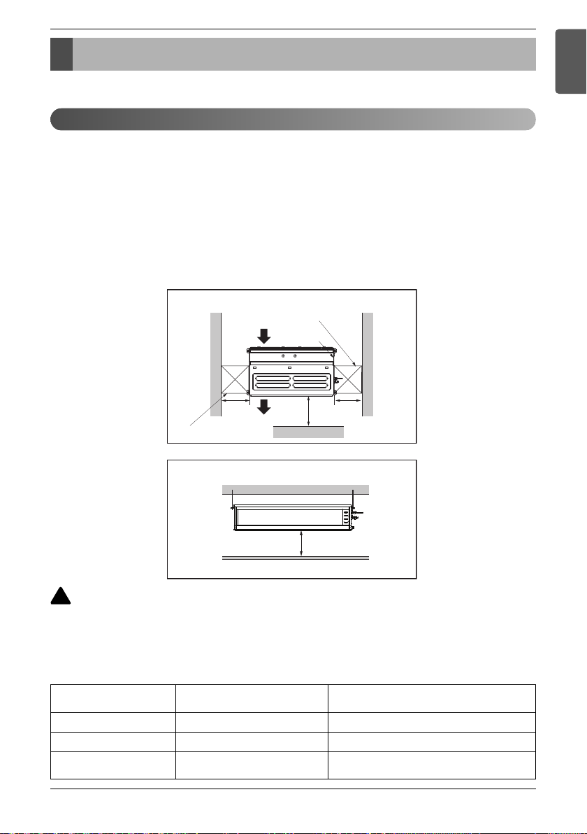
Front view (Unit: mm)
(Unit: mm)
Top view
Front
Inspection hole(1)
600 x 600
Inspection hole(2)
600 x 600
Control box
1 000
Air outlet vents
Air inlet vents
600
600
More than 20
Installation
Read completely, then follow step by step.
Selection of the best location
Install the air conditioner in the location that satisfies the following conditions.
• The place shall easily bear a load exceeding four times the indoor unit’s weight.
• The place shall be able to inspect the unit as the figure.
• The place where the unit shall be leveled.
•
The place shall allow easy water drainage.
• The place shall easily connect with the outdoor unit.
• The place where the unit is not affected by an electrical noise.
• The place where air circulation in the room will be good .
• There should not be any heat source or steam near the unit.
Installation
ENGLISH
!
CAUTION
In case that the unit is installed near the sea, the installation parts may be corroded by
salt, The installation parts (and the unit) should be taken appropriate anti-corrosion
measures.
[Inspection Hole Standard]
Number of
inspection hole
1 More than 100 cm
false ceiling & actual ceiling
2 20 cm to 100 cm
Hole size should be more
than the size of IDU.
Distance between
Less than 20 cm
Remarks
Sufficient space in the ceiling for servicing.
Insufficient space. Difficult for servicing
Minimum height for motor replacement.
Installation Manual 7
Page 8

Installation
NOTICE
Ceiling dimension and hanging bolt location
n Installation of Unit
Install the unit above the ceiling correctly.
D
POSITION OF SUSPENSION BOLT
• Apply a joint-canvas between the unit and duct
to absorb unnecessary vibration.
• Install the unit leaning to a drainage hole side
as a figure for easy water drainage.
• A place where the unit will be leveled and that
can support the weight of the unit.
A place where the unit can withstand its vibration.
•
• A place where service can be easily performed.
E
C
J
A
B
I
F
H
G
Drain hole
M10 Nut
M10 washer
M10 washer
M10 Nut
Dimension
Chassis name
M1 933.4 971.6 619.2 700 30 270 15.2 858 201.4 900
M2 1 283.4 1 321.6 619.2 700 30 270 15.2 1 208 201.4 1 250
M3 1 283.4 1 321.6 619.2 700 30 360 15.2 1 208 291.4 1 250
A B C D E F G H I J
X 4
X 4
X 4
X 8
(Unit:mm)
• Throughly study the following installation locations:
1. In such places as restaurants and kitchens, considerable amount of oil steam and flour adhere to the fan, the fin of the heat
exchanger, resulting in heat exchange reduction, spraying, dispersing of water drops, etc. In these cases, take the following actions:
• Make sure that the ventilation fan for smoke-collecting hood on a cooking table has sufficient capacity so that it draws oily steam
which should not flow into the suction of the air conditioner.
• Make enough distance from a cooking room to install the air conditioner in such a place where it may not suck in oil steam.
2. Avoid installing air conditioner in such circumstances where cutting oil mist or iron powder is in suspension in factories, etc.
3. Avoid places where inflammable gas is generated, flows in, is stored or vented.
4. Avoid places where sulfurous acid gas or corrosive gas is generated.
5. Avoid places near high frequency generators.
8 Indoor Unit
Page 9

Indoor Unit Installation
Installation
ENGLISH
• Select and mark the position for fixing bolts.
Drill the hole for set anchor on the face of ceiling.
•
• Insert the set anchor and washer onto the
suspension bolts for locking the suspension
bolts on the ceiling.
Mount the suspension bolts to the set anchor firmly.
•
• Secure the installation plates onto the
suspension bolts (adjust level roughly) using
nuts, washers and spring washers.
Old building New building
1 Set anchor
2 Plate washer
3 Spring washer
4 Nut
!
CAUTION
Tighten the nut and bolt to prevent unit falling.
5 Suspension
bolts
Wiring Connection
Connect the wires to the terminals on the control board individually according to the outdoor unit connection.
• Ensure that the color of the wires of outdoor unit and the terminal No. are the same as those of indoor
unit respectively.
<M1 Chassis>
Terminal Block Indoor
1(L) 2(N)
INDOOR POWER INPUT
<M2/M3 Chassis>
Terminal Block Indoor
Terminal Block Indoor
34
GN/YL
Terminal Block Indoor
1(L) 2(N)
Outdoor unit
Indoor unit
ODU ODU
IDU IDU
Terminal Block Indoor
34
INTERNET
Outdoor unit
ODU ODU
Central controller
DRY1
DRY2
Indoor unit
INTERNET
IDU IDU
Outdoor unit
12V
GND
Central controller
DRY1
DRY2
GND
12V
Outdoor unit
INDOOR POWER INPUT
GN/YL
!
WARNING
Make sure that the screws of the terminal are free from looseness.
• Communication and Power Cable
1. Communication Cable : CVV-SB 1.0~1.5x2C
2. Power Cable : H07RN-F 1.5x3C
Clamping of cables
1) Arrange 2 power cables on the control panel.
2) First, fasten the steel clamp with a screw to the inner boss of control panel.
3) For the cooling model, fix the other side of the clamp with a screw strongly. For the heat pump
model, put the 0.75mm
2
cable(thinner cable) on the clamp and tighten it with a plastic clamp to
the other boss of the control panel.
!
CAUTION
The Power cord connected to the unit should be selected according to the following
specifications.
Installation Manual 9
Page 10

Installation
Air outlet vents
Air filters
INSULATION, OTHERS
THERMAL INSULATION
INDOOR UNIT
Liquid pipe
Clamp for insulation
(Local supply)
Insulation
(Local supply)
Union for gas pipe
Checking the Drainage
1. Remove the Air Filter.
Insulate the joint and tubes completely.
All thermal insulation must comply with local requirement.
Refrigerant pipe and thermal
insulation(Local supply)
Thermal insulator for refrigerant pipe
(Local supply)
Hose clip for thermal insulator(Local supply)
Make sure that there is no clearance here.
Thermal insulator for
piping(Local supply)
Overlap with thermal
insulator for piping.
2. Check the drainage.
10 Indoor Unit
• Spray one or two glasses of water upon the
evaporator.
• Ensure that water flows drain hose of indoor
unit without any leakage.
Page 11

Installation
Maintenance
drain port
Upward
routing
not allowed
Pipe clamp
Indoor unit
1/50~1/100
MAX 700 mm
Feed water
Drain Pump
Drain pan
Flexible drain hose
(accessory)
Main
drain pipe
Glue the joint
Drain
port
Drain hose connection
Use the clip (accessory)
1/50~1/100 slope
Hanger
distance
Hanger Bracket
Max 700 mm
Flexible drain hose
Insulation
Metal
clamp
Max 300 mm
1~15 m
!
CAUTION
1. Install declination of the indoor unit is very important for the drain of the duct type air
conditioner.
2. Minimum thickness of the insulation for the connecting pipe shall be 5 mm.
Front of view
• The unit must be horizontal or declined to the drain hose connected when finished installation.
Ceiling
1~3 mm
Drainage hole
Indoor Unit Drain Piping
•
Drain piping must have down-slope (1/50 to 1/100): be sure
not to provide up-and-down slope to prevent reversal flow.
• During drain piping connection, be careful not to exert
extra force on the drain port on the indoor unit.
• The outside diameter of the drain connection on the
indoor unit is 32 mm.
Piping material: Polyvinyl chloride pipe inner
diometes Ø 25 mm and pipe fittings
• Be sure to install heat insulation on the drain piping.
Heat insulation material: Polyethylene foam
with thickness more than 8 mm.
ENGLISH
Drain test
The air conditioner uses a drain pump to drain water.
Use the following procedure to test the drain pump operation:
• Connect the main drain pipe to the exterior and leave
it provisionally until the test comes to an end.
• Feed water to the flexible drain hose and check the
piping for leakage.
• Be sure to check the drain pump for normal operation
and noise when electrical wiring is complete.
!
CAUTION
The supplied flexible drain hose should
not be strained. A strained hose may
cause leakage of water.
• When the test is complete, connect the flexible drain
hose to the drain port on the indoor unit.
Installation Manual 11
Page 12

Installation
!
CAUTION
After the confirmation of the above conditions, prepare the wiring as follows:
1) Never fail to have an individual power specialized for the air conditioner. As for the
method of wiring, be guided by the circuit diagram posted on the inside of control
box cover.
2) Provide a circuit breaker switch between power source and the unit.
3) The screws which fasten the wiring in the casing of electrical fittings are liable to
come loose from vibrations to which the unit is subjected during the course of
transportation. Check them and make sure that they are all tightly fastened. (If they
are loose, it could give rise to burn-out of the wires.)
4) Specification of power source
5) Confirm that electrical capacity is sufficient.
6) Be sure that the starting voltage is maintained at more than 90 percent of the rated
voltage marked on the name plate.
7) Confirm that the cable thickness is as specified in the power sources specification.
(Particularly note the relation between cable length and thickness.)
8) Never fail to equip a leakage breaker where it is wet or moist.
9) The following troubles would be caused by voltage drop-down.
• Vibration of a magnetic switch, damage on the contact point, fuse breaking, disturbance
by the normal function of an overload protection device.
• Proper starting power is not given to the compressor.
HAND OVER
Teach the customer the operation and maintenance procedures, using the operation manual.
(air filter cleaning, temperature control, etc.)
12 Indoor Unit
Page 13

Installation
DIP Switch Setting
1. Indoor Unit
Function Description Setting Off Setting On Default
SW1 Communication N/A (Default) - - Off
SW2 Cycle N/A (Default) - - Off
SW3 Group Control
Dry Contact
SW4
Mode
SW5 Installation
SW6 Heater linkage N/A - - Off
Ventilator
linkage
Vane selection
SW7
(Console)
Region
selection
SW8 Etc. Spare - - Off
Selection of Master or
Slave
Selection of Dry
Contact Mode
Fan continuous
operation
Selection of Ventilator
linkage
Selection of up/down
side Vane
Selection tropical
region
Master Slave Off
Wired/Wireless remote
controller
selection of Manual or Auto
operation Mode
Continuous operation
Removal
Linkage Removal Working
Up side + Down side Vane
General model
Auto Off
- Off
Up side Vane
Only
Tropical
model
ENGLISH
Off
!
CAUTION
For Multi V Models, DIP switch 1, 2, 6, 8 must be set OFF.
2. Outdoor Unit
In case that the products meet specific conditions, “Auto addressing” function can start automatically
with the improved speed by turning the DIP switch #3 of the outdoor unit and resetting the power.
※ Specific conditions:
- All names of the indoor units are ARNU****4.
- The serial number of Multi V super IV (outdoor units) is after October 2013.
DIP switch 7 segment
Outdoor Unit PCB Outdoor Unit DIP Switch
Installation Manual 13
Page 14

Installation
Group Control Setting
1. Group Control 1
n Wired remote controller 1 + Standard Indoor Units
Master Slave Slave Slave
Master
n DIP Switch in PCB
¿ Master Setting
- No. 3 Off
Display Error Message
Indoor Unit DIP Switch
or
Only connect serial signal and GND lines
between indoor units.
¡ Slave Setting
- No. 3 On
LGAP Network System
GND
Signal
12 V
Some products have no DIP switch on PCB. It is possible to set indoor units to Master or Slave by
using the wireless remote controller instead of DIP switch.
For the details of the setting, please refer to the manual of the wireless remote controller.
1. It is possible to 16 indoor units(Max.) by one wired remote controller.
Set only one indoor unit to Master, set the others to Slave.
2. It is possible to connect with every type of indoor units.
3. It is possible to use wireless remote controller at the same time.
4. It is possible to connect with Dry Contact and Central controller at the same time.
- The Master indoor unit is possible to recognize Dry Contact and Central Controller only.
5. In case that any error occurs at indoor unit, the error code is displayed on the wired remote
controller.
It is possible to control the other indoor units except the error units.
14 Indoor Unit
Page 15

h It is possible to connect indoor units since Feb. 2009.
h It can be the cause of malfuctions when there is no setting of master and slave.
h In case of Group Control, it is possible to use following functions.
- Selection of operation, stop or mode
- Temperature setting and room temperature check
- Current time change
- Control of flow rate (High/Middle/Low)
- Reservation settings
It is not possible to use some functions.
2. Group Control 2
n Wired remote controllers + Standard Indoor Units
Installation
ENGLISH
or
Master Master Slave Slave
Donʼt connect serial 12V line
Display Error Message
Master Master
LGAP Network System
GND
Signal
12 V
h It is possible to control 16 indoor units(Max.) with the master wired remote control.
h Other than those, it is same with the Group Control 1.
Installation Manual 15
Page 16

Installation
3. Group Control 3
n Mixture connection with indoor units and Fresh Air Intake Unit
LGAP Network System
Slave
FAU
Master
Master
FAU
Slave
or
Master
MN
Display Error Message
Master Master
Display Error Message
h In case of connecting with standard indoor unit and Fresh Air Intake Unit, separate Fresh Air
Intake Unit with standard units. (N, M ≤ 16) (Because setting temperature are different.)
h Other than those, it is same with Group Control 1.
FAU
Standard Standard
FAU FAU
FAU
Standard Standard
GND
Signal
12 V
16 Indoor Unit
* FAU : Fresh Air Intake Unit
Standard: Standard Indoor Unit
Page 17

4. 2 Remote Control
n Wired remote controller 2 + Indoor unit 1
Installation
ENGLISH
LGAP Network System
Slave
GND
Signal
12 V
Master
Master
Display Error Message
Slave
Slave
or
Slave
1. It is possible to connect two wired remote controllers (Max.) with one indoor unit.
Set only one indoor unit to Master, set the others to Slave.
Set only one wired remote controller to Master, set the others to Slave.
2. Every types of indoor unit is possible to connect two remote controller.
3. It is possible to use wireless remote controller at the same time.
4. It is possible to connect with Dry Contact and Central controller at the same time.
5. In case that any error occurs at indoor unit, the error code is displayed on the wired
remote controller.
6. There isnʼt limits of indoor unit function.
Installation Manual 17
Page 18

Installation
5. Accessories for group control setting
It is possible to set group control by using below accessories.
Indoor unit 2 EA + Wired remote controller 1 EA
h
PZCWRCG3 cable used for connection
Mas te r
!
CAUTION
• Apply totally enclosed noncombustible conduit in case of local building code Requiring plenum
cable usage.
Slave
PZCWRCG3
Mas ter
Indoor unit 1 EA + Wired remote controller 2 EA
h
PZCWRC2 cable used for connection
PZCWRC2
Mas ter S lave
18 Indoor Unit
Page 19

ARN U G28 AM2 4
Serial Number
Chassis Name
Electrical Ratings
1 : 1Ø, 115 V, 60 Hz
6 : 1Ø, 220 - 240 V, 50 Hz
3 : 1Ø, 208/230 V, 60 Hz
2 : 1Ø, 220 V, 60 Hz
7 : 1Ø, 100 V, 50/60 Hz
G
: 1Ø, 220 - 240 V, 50 Hz/1Ø, 220 V, 60 Hz
Total Cooling Capacity in Btu/h
EX) 5 000 Btu/h ➝ '05' 18 000 Btu/h ➝ '18'
Combination of Inverter Type and Cooling Only or Heat Pump
N : AC Inverter and H/P V : AC Inverter and C/O
U : DC Inverter and H/P and C/O
System with Indoor Unit using R410A
❈ LGETA : U Ex) URN
Combinations of functions
A : Basic function L : Neo Plasma(Wall Mounted)
C : Plasma(Ceiling Cassette) B : High Static
G : Low Static K : High Sensible Heat
U : Floor Standing without Case
SE/S8 - R : Mirror V : Silver B : Blue(ART COOL Type Panel Clolr)
SF - E : Red V : Silver G : Gold 1 : Kiss (Photo changeable)
Q : Console Z : Fresh Air Intake Unit
Model Designation
Airborne Noise Emission
The A-weighted sound pressure emitted by this product is below 70 dB.
** The noise level can vary depending on the site.
The figures quoted are emission level and are not necessarily safe working levels. Whilst there is a
correlation between the emission and exposure levels, this cannot be used reliably to determine
whether or not further precautions are required. Factor that influence the actual level of exposure of the
workforce include the characteristics of the work room and the other sources of noise, i.e. the number
of equipment and other adjacent processes and the length of time for which an operator exposed to the
noise. Also, the permissible exposure level can vary from country to country. This information, however,
will enable the user of the equipment to make a better evaluation of the hazard and risk.
Limiting concentration
Limiting concentration is the limit of Freon gas concentration where immediate measures can be
taken without hurting human body when refrigerant leaks in the air. The limiting concentration shall
be described in the unit of kg/m
n Calculate refrigerant concentration
Refrigerant concentration =
Installation
3
(Freon gas weight per unit air volume) for facilitating calculation
Limiting concentration : 0.44 kg/m3(R410A)
Total amount of replenished refrigerant in refrigerant facility (kg)
Capacity of smallest room where indoor unit is installed (m
Installation Manual 19
3
)
ENGLISH
Page 20

How to Set E.S.P?
How to Set E.S.P?
ARNU**GM1A4 (** : 07, 09, 12, 15, 18)
Setting
value
70 11.3 - - - ---75 12.8 - - - ---80 14.4 11.4 - - ---85 15.9 13.2 10.2 - ---90 17.5 15.0 12.0 - ----
95 19.0 16.7 13.7 10.7 ---100 20.6 18.5 15.5 12.5 ---105 22.1 20.3 17.3 14.3 11.1 - - 110 23.7 22.1 19.0 16.1 13.1 10.0 - 115 - 23.8 20.8 17.9 15.1 12.2 - 120 - - 22.6 19.7 17.1 14.3 11.3 125 - - - 21.5 19.1 16.5 13.6 11.9
130 - - - 23.3 21.2 18.7 15.8 14.3
135 - - - - 23.2 20.8 18.0 16.7
140 - - - - - 23.0 20.3 19.1
145 - - - - - - 22.5 21.5
150 - - - - - - - 23.8
2.5(25) 4(39) 6(59) 8(78) 10(98) 12(118) 14(137) 15(147)
Static Pressure (mmAq(Pa))
ARNU**GM1A4 (** : 24)
Setting
value
85 16.8 14.6 - - ----
90 18.1 15.9 - - ----
95 19.4 17.2 15.0 - ---100 20.7 18.5 16.3 13.9 ---105 22.0 19.8 17.7 15.3 13.0 - - 110 23.3 21.1 19.1 16.8 14.6 - - 115 24.6 22.4 20.5 18.3 16.3 14.2 - 120 25.9 23.7 21.8 19.7 17.9 15.9 13.3 125 - 25.1 23.2 21.2 19.6 17.5 15.2 14.6
130 - - 24.6 22.7 21.2 19.2 17.1 16.3
135 - - - 24.2 22.9 20.9 19.0 18.1
140 - - - - 24.5 22.6 20.9 19.9
2.5(25) 4(39) 6(59) 8(78) 10(98) 12(118) 14(137) 15(147)
Static Pressure (mmAq(Pa))
ARNU**GM2A4 (** : 07, 09, 12, 15)
Setting
value
654.7------70 10.3 ------75 15.0 ------80 19.0 7.6 -----85 24.9 13.8 4.9 ----90 27.6 20.4 7.8 -----
95 30.4 24.4 15.7 5.2 ---100 33.1 28.7 20.8 9.2 3.8 - - 105 35.9 31.7 24.1 17.5 6.7 - - -
110 38.6 34.7 30.5 22.2 11.5 5.5 - -
115 40.1 37.8 33.8 27.9 20.2 9.1 - 120 - 39.1 37.1 31.4 24.6 17.9 7.5 125 - - 38.5 35.0 30.1 21.2 11.0 6.7
130 - - - 37.1 32.0 27.6 15.6 10.0
135----36.8 31.5 24.3 16.2
140----40.5 35.9 29.8 22.4
145-----39.9 34.9 27.8
150------39.4 34.2
155-------37.1
Note: 1. The above table shows the correlation between the air rates and E.S.P.
2. Make sure to check and adjust E.S.P (external static pressure) value after the installation of the product.
4(39) 6(59) 8(78) 10(98) 12(118) 14(137) 16(157) 18(177)
Otherwise, there is a risk of weak cooling/heating and condensed water discharge/drop.
Static Pressure (mmAq(Pa))
(Unit: CMM)
(Unit: CMM)
(Unit: CMM)
20 Indoor Unit
Page 21

How to Set E.S.P?
ARNU**GM2A4 (** : 28, 36)
Setting
value
4(39) 6(59) 8(78) 10(98) 12(118) 14(137) 16(157) 18(177)
654.7------70 10.3 ------75 15.0 ------80 19.0 7.6 - - - - - 85 24.9 13.8 4.9 - - - - 90 27.6 20.4 7.8 - - - - -
95 30.4 24.4 15.7 5.2 - - - 100 33.1 28.7 20.8 9.2 3.8 - - 105 35.9 31.7 24.1 17.5 6.7 - - 110 38.6 34.7 30.5 22.2 11.5 5.5 - 115 40.1 37.8 33.8 27.9 20.2 9.1 - 120 - 39.1 37.1 31.4 24.6 17.9 7.5 125 - - 38.5 35.0 30.1 21.2 11.0 6.7
130 - - - 37.1 32.0 27.6 15.6 10.0
135 - - - - 36.8 31.5 24.3 16.2
140 - - - - 40.5 35.9 29.8 22.4
145-----39.9 34.9 27.8
150------39.4 34.2
155-------37.1
Static Pressure (mmAq(Pa))
(Unit: CMM)
ENGLISH
ARNU**GM2A4 (** : 42)
Setting
value
4(39) 6(59) 8(78) 10(98) 12(118) 14(137) 16(157) 18(177)
Static Pressure (mmAq(Pa))
(Unit: CMM)
90 23.0 -------
95 25.9 19.1 - - - - - 100 28.6 23.3 - - - - - 105 31.4 26.4 19.6 - - - - -
110 34.2 29.9 24.2 - - - - -
115 36.6 32.7 28.8 21.7 - - - 120 39.2 35.7 31.8 26.2 19.6 - - 125 41.7 38.5 34.8 30.8 24.3 - - 130 44.0 41.2 37.7 34.1 29.0 22.3 - 135 - 43.8 40.7 37.4 32.6 27.5 20.5 140 - - 43.5 40.4 37.2 32.6 25.8 19.9
145 - - - 43.4 41.6 37.4 30.7 24.6
150----43.4 42.3 35.4 29.4
155-----43.7 37.5 32.7
ARNU**GM3A4 (** : 18, 24, 28)
Setting value
70 25.2 -------75 30.4 21.4 ------80 35.0 27.2 18.5 -----85 39.8 35.4 24.6 -----90 44.3 40.1 31.5 22.7 ----
95 49.3 44.8 36.8 28.8 21.4 ---100 53.0 49.4 44.6 35.4 27.7 ---105 57.2 54.1 49.2 43.0 35.0 26.5 - - 110 - 58.8 53.9 47.9 42.4 33.8 24.3 14.8 115 - - 58.6 52.9 47.8 42.5 31.4 20.3 18.3
120 - - - 57.8 53.1 48.2 39.2 30.2 24.6
125-----49.4 43.1 36.7 33.1
130-----52.7 48.6 44.4 39.6
135-------50.2 45.2
Note: 1. The above table shows the correlation between the air rates and E.S.P.
2. Make sure to check and adjust E.S.P (external static pressure) value after the installation of the product.
4(39) 6(59) 8(78) 10(98) 12(118) 14(137) 16(157) 18(177) 20(196)
Otherwise, there is a risk of weak cooling/heating and condensed water discharge/drop.
Static Pressure (mmAq(Pa))
(Unit: CMM)
Installation Manual 21
Page 22

How to Set E.S.P?
ARNU**GM3A4 (** : 48, 54)
Setting value
70 25.1 - - - - - -
75 29.5 26.1 - - - - -
80 34.0 30.8 25.9 - - - -
85 38.4 35.4 30.6 32.2 - - -
90 42.9 40.1 35.2 28.1 21.0 - -
95 47.3 44.8 39.9 33.1 26.3 19.5 100 51.8 49.4 44.6 38.0 31.7 25.2 22.6
105 56.2 54.1 49.2 43.0 37.1 31.0 28.5
110 - 58.8 53.9 47.9 42.4 36.7 34.4
115 - - 58.6 52.9 47.8 42.5 40.3
120 - - - 57.8 53.1 48.2 46.1
125----54.2 49.4 47.3
5(49) 6(59) 8(78) 10(98) 12(118) 14(137) 15(147)
Static Pressure (mmAq(Pa))
(Unit: CMM)
ARNU**GM3B4 (** : 48, 54)
Setting value
70 25.2 --------
75 30.4 21.4 -------
80 35.0 27.2 18.5 ------
85 39.8 35.4 24.6 ------
90 44.3 40.1 31.5 22.7 -----
95 49.3 44.8 36.8 28.8 21.4 ---100 53.0 49.4 44.6 35.4 27.7 ---105 57.2 54.1 49.2 43.0 35.0 26.5 - - 110 - 58.8 53.9 47.9 42.4 33.8 24.3 14.8 115 - - 58.6 52.9 47.8 42.5 31.4 20.3 18.3
120 - - - 57.8 53.1 48.2 39.2 30.2 24.6
125-----49.4 43.1 36.7 33.1
130-----52.7 48.6 44.4 39.6
135------ 55.3 50.2 45.2
4(39) 6(59) 8(78) 10(98) 12(118) 14(137) 16(157) 18(177) 20(196)
ARNU**GM3A4 (** : 60)
Setting value
70
75
80
85
90
95
100
105
110
115
120
125
5(49) 6(59) 8(78) 10(98)
25.1 - - -
29.5 26.1 - -
34.0 30.8 25.9 -
38.4 35.4 30.6 32.2
42.9 40.1 35.2 28.1
47.3 44.8 39.9 33.1
51.8 49.4 44.6 38.0
56.2 54.1 49.2 43.0
Static Pressure (mmAq(Pa))
- 58.8 53.9 47.9
- - 58.6 52.9
- - - 57.8
----
Static Pressure (mmAq(Pa))
(Unit: CMM)
(Unit: CMM)
Note: 1. The above table shows the correlation between the air rates and E.S.P.
2. Make sure to check and adjust E.S.P (external static pressure) value after the installation of the product.
Otherwise, there is a risk of weak cooling/heating and condensed water discharge/drop.
22 Indoor Unit
 Loading...