

Page 1

INSTALLATION MANUAL
AIR
CONDITIONER
Please read this installation manual completely before installing the product.
Installation work must be performed in accordance with the national wiring
standards by authorized personnel only.
Please retain this installation manual for future reference after reading it
thoroughly.
Ceiling Suspended Air Conditioner
Original instruction
P/NO : MFL67107610
REV.00_062816
www.lg.com
Page 2

TIPS FOR SAVING ENERGY
2
ENGLISH
TIPS FOR SAVING ENERGY
Here are some tips that will help you minimize the power consumption when you use the air
conditioner. You can use your air conditioner more efficiently by referring to the instructions
below:
• Do not cool excessively indoors. This may be harmful for your health and may consume more
electricity.
• Block sunlight with blinds or curtains while you are operating the air conditioner.
• Keep doors or windows closed tightly while you are operating the air conditioner.
• Adjust the direction of the air flow vertically or horizontally to circulate indoor air.
• Speed up the fan to cool or warm indoor air quickly, in a short period of time.
• Open windows regularly for ventilation as the indoor air quality may deteriorate if the air conditioner is used for many hours.
• Clean the air filter once every 2 weeks. Dust and impurities collected in the air filter may block the
air flow or weaken the cooling / dehumidifying functions.
For your records
Staple your receipt to this page in case you need it to prove the date of purchase or for warranty
purposes. Write the model number and the serial number here:
Model number :
Serial number :
You can find them on a label on the side of each unit.
Dealer’s name :
Date of purchase :
Page 3

IMPORTANT SAFETY INSTRUCTIONS
IMPORTANT SAFETY INSTRUCTIONS
READ ALL INSTRUCTIONS BEFORE USING THE APPLIANCE.
Always comply with the following precautions to avoid dangerous situations and ensure peak
performance of your product
WARNING
!
It can result in serious injury or death when the directions are ignored
CAUTION
!
It can result in minor injury or product damage when the directions are ignored
WARNING
!
• Installation or repairs made by unqualified persons can result in hazards to you and others.
• Installation MUST conform with local building codes.
• The information contained in the manual is intended for use by a qualified service technician
familiar with safety procedures and equipped with the proper tools and test instruments.
• Failure to carefully read and follow all instructions in this manual can result in equipment malfunction, property damage, personal injury and/or death.
Installation
• Don’t use a power cord, a plug or a loose socket which is damaged.
- Otherwise, it may cause a fire or electrical shock.
• For electrical work, contact the dealer, seller, a qualified electrician, or an Authorized Service Center.
- Do not disassemble or repair the product. There is risk of fire or electric shock.
• Always ground the product.
- There is risk of fire or electric shock.
• Install the panel and the cover of control box securely.
- There is risk of fire or electric shock.
• Always install a dedicated circuit and breaker.
- Improper wiring or installation may cause fire or electric shock.
• Use the correctly rated breaker or fuse.
- There is risk of fire or electric shock.
• Do not modify or extend the power cable.
- There is risk of fire or electric shock.
• Do not let the air conditioner run for a long time when the humidity is very high and a door or a window is left open.
- Moisture may condense and wet or damage furniture.
• Be cautious when unpacking and installing the product.
- Sharp edges could cause injury. Be especially careful of the case edges and the fins on the con-
denser and evaporator.
• For installation, always contact the dealer or an Authorized Service Center.
- There is risk of fire, electric shock, explosion, or injury.
3
ENGLISH
Page 4

4
ENGLISH
Operation
Installation
IMPORTANT SAFETY INSTRUCTIONS
• Do not install the product on a defective installation stand.
- It may cause injury, accident, or damage to the product.
• Be sure the installation area does not deteriorate with age.
- If the base collapses, the air conditioner could fall with it, causing property damage, product failure,
and personal injury.
• There is a risk of fire and explosion.
- Inert gas (nitrogen) should be used when you check plumbing leaks, cleaning or repairs of pipes
etc.
If you are using combustible gases including oxygen, product may have the risk of fires and explosions.
• Use a vacuum pump or Inert (nitrogen) gas when doing leakage test or air purge. Do not compress
air or Oxygen and do not use Flammable gases. Otherwise, it may cause fire or explosion.
- There is the risk of death, injury, fire or explosion.
• Do not store or use flammable gas or combustibles near the product.
- There is risk of fire or failure of product.
CAUTION
!
• Always check for gas (refrigerant) leakage after installation or repair of product.
- Low refrigerant levels may cause failure of product.
• Install the drain hose to ensure that water is drained away properly.
- A bad connection may cause water leakage.
• Keep level even when installing the product.
- To avoid vibration or water leakage.
• Use two or more people to lift and transport the product.
- Avoid personal injury.
Page 5

TABLE OF CONTENTS
TABLE OF CONTENTS
5
ENGLISH
2
TIPS FOR SAVING EN-
ERGY
3
IMPORTANT SAFETY INSTRUCTIONS
6
PRODUCT PARTS
INSTALLATION TOOLS
6
7
INSTALLATION
7 Select the best Location
8
THE INDOOR UNIT IN-
STALLATION
9 Open side-cover
10 Mounting the anchor nut and bolt
12 Indoor unit drain piping
12 Drain piping
12 Drain test
13 Heat insulation
Connecting Cables to the indoor unit
13
13 Flaring Work
16 Wiring Connection
17 DIP Switch Setting
18 Group Control Setting
23 Model Designation
23 Airborne Noise Emission
23 Limiting concentration
Page 6
PRODUCT PARTS
6
ENGLISH
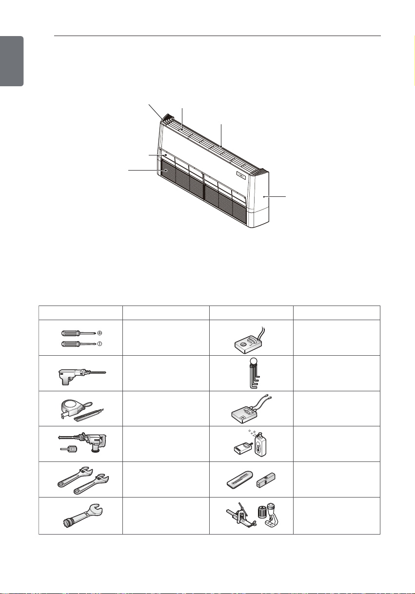
PRODUCT PARTS
Right side cover
Air filters
(behind inlet grille)
Air inlet vent
(inlet grille)
Louver
INSTALLATION TOOLS
Screw driver
Electric drill
Air outlet vent
erugiFerugiF Name
Left side cover
Name
Multi-meter
Hexagonal wrench
Measuring tape, Knife
Hole core drill
Spanner
Torque wrench
Ammeter
Gas-leak detector
Thermometer,
Level
Flaring tool set
Page 7
INSTALLATION MAP
INSTALLATION
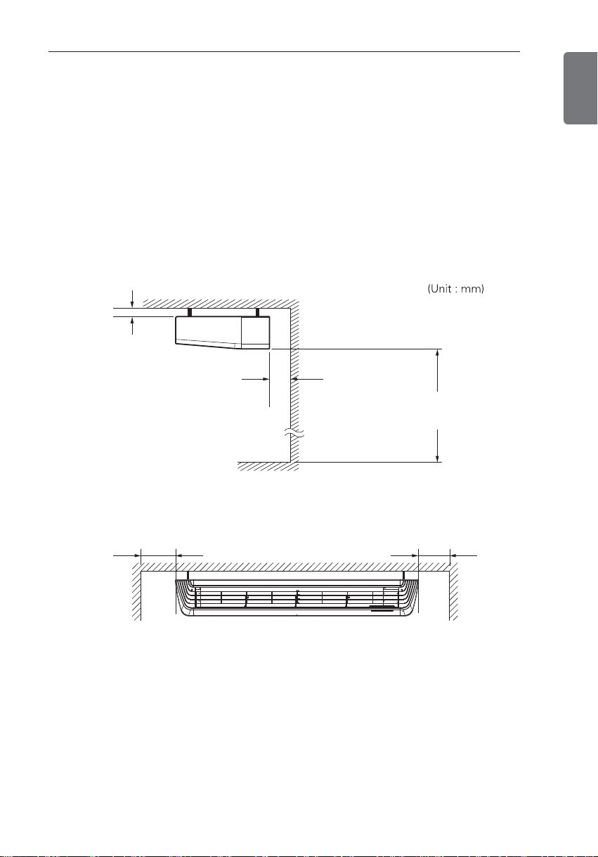
Select the best Location
- There should not be any heat source or steam near the unit.
- There should not be any obstacles to prevent the air circulation.
- A place where air circulation in the room will be good.
- A place where drainage can be easily obtained.
- A place where noise prevention is taken into consideration.
- Do not install the unit near the door way.
- Ensure the spaces indicated by arrows from the wall, ceiling, or other obstacles.
- The indoor unit must keep the maintenance space.
10 (13/32)
or more
300 (11 – 13/16)
or more
2500 (98 – 3/7)
or more
7
ENGLISH
Floor
700(27 – 9/16) or more 700(27 – 9/16) or more
Page 8
THE INDOOR UNIT INSTALLATION
8
ENGLISH
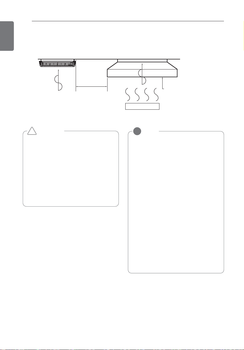
THE INDOOR UNIT INSTALLATION
Air conditioner
Take enough
distance
Cooking table
Use the ventilation fan
for smoke-collecting
hood with sufficient
capacity.
CAUTION
!
• Install the unit horizontally using a level
gauge.
• During the installation, care should be
taken not to damage electric wires.
• Select and mark the position for fixing
bolts and piping hole.
• Decide the position for fixing bolts
slightly tilted to the drain direction after
considering the direction of drain hose.
• Drill the hole for anchor bolt on the ceiling.
NOTE
!
• Avoid the following installation location.
1. Such places as restaurants and kitchen
where considerable amount of oil
steam and flour is generated.
These may cause heat exchange efficiency reduction, or water drops, drain
pump mal-function.
In these cases, take the following actions;
• Make sure that ventilation fan is enough
to cover all noxious gases from this
place.
• Ensure enough distance from the cook-
ing room to install the air conditioner in
such a place where it may not suck oily
steam.
2. Avoid installng air conditioner in such
places where cooking oil or iron powder is generated.
3. Avoid places where inflammable gas is
generated.
4. Avoid place where noxious gas is generated.
5. Avoid places near high frequency generators.
Page 9

Open side-cover
Step 1
THE INDOOR UNIT INSTALLATION
- Remove paper bracket from side-cover.
9
ENGLISH
- Remove two screws from side-cover.
Step 2
Right side cover
Left side
Backside
Backside
- Unlock side-cover from side-panel slightly
(Tap the side-cover with your palm on the
backside)
cover
Step 4
- Knock out the pipe hole from the left sidecover with nipper/plier.
CAUTION
!
Hold the side-cover with other hand while
tapping to prevent it to fall down.
Page 10

Chassis Code
VM1 ARNU**GV1A4 1018 355
Page 11

THE INDOOR UNIT INSTALLATION
Ceiling
10~20 mm
Ceiling
5~10 mm
CAUTION
!
Installation information for declination
- Install declination of the indoor unit is very important for the drain of the convertible type air
conditioner.
- Minimum thickness of the insulation for the connecting pipe shall be 10 mm.
- If the Installation Plates are fixed to horizontal line, the indoor unit after installing will be declined to the bottomside.
Front of view
- The unit must be horizontal or inclined at angle.
- The inclination should be less than or equal to 1° or in between 10 to 20 mm inclined in drain
direction as shown in fig.
11
ENGLISH
Side of view
- The unit must be inclined to the bottomside of the unit when finished installation.
Page 12

Page 13

Page 14

14
ENGLISH
THE INDOOR UNIT INSTALLATION
Putting nut on
- Remove flare nuts attached to indoor and
outdoor unit, then put them on pipe/tube
having completed burr removal.
(not possible to put them on after finishing
flare work)
Flare nut
Copper tube
Flaring work
Firmly hold copper pipe in a bar with the di-
1
mension shown in below table table
below.
2
Carry out flaring work with the flaring tool.
Outside diameter
mm inch mm
Ø6.35 1/4 1.1~1.3
Ø9.52 3/8 1.5~1.7
Ø12.7 1/2 1.6~1.8
Ø15.88 5/8 1.6~1.8
Ø19.05 3/4 1.9~2.1
Bar
"A"
Bar
A
Handle
Yoke
Cone
Check
Compare the flared work with the figure
1
by.
2
If a flared section is defective, cut it off
and do flaring work again.
Smooth all round
Inside is shiny without scratches
= Improper flaring =
Surface
Even length
all round
Inclined
damaged
Cracked Uneven
Connecting the installation pipe
and drain hose to the indoor unit.
1
Align the center of the pipes and sufficiently tighten the flare nut by hand
Indoor unit tubing Flare nut Pipes
2
Tighten the flare nut with a wrench
Outside diameter
mm inch kgf.m
Ø6.35 1/4 1.8~2.5
Ø9.52 3/8 3.4~4.2
Ø12.7 1/2 5.5~6.5
Ø15.88 5/8 6.3~8.2
Ø19.05 3/4 9.9~12.1
Torque
Open-end wrench
(fixed)
thickness
Copper pipe
Clamp handle
Red arrow mark
Wrench
Indoor unit tubing
Flare nut
Connection
pipe
Page 15

THE INDOOR UNIT INSTALLATION
Gas Pipe
Liquid Pipe
Cutting Line
Cutting Line
Good Case Bad Case
* Tubing cutting line have to be upward.
Vinyl tape(narrow)
Connection pipe
Connecting cable
Vinyl tape (wide)
Wrap with vinyl tape
Indoor unit pipe
Pipe
15
ENGLISH
When needed to extend the drain hose of
3
indoor unit, assembly the drain pipe as
shown on the drawing
Drain pipe
Indoor unit drain hose
Vinyl tape(narrow)
Adhesive
Wrap the insulation material
around the connecting portion.
Overlap the connection pipe insulation ma-
1
terial and the indoor unit pipe insulation
material. Bind them together with vinyl
tape so that there may be no gap.
Insulation material
2
Set the tubing cutting line upward.
Wrap the area which accommodates the
rear piping housing section with vinyl tape.
Bundle the piping and drain hose together
3
by wrapping them with vinyl tape sufficient
enough to cover where they fit into the
rear piping housing section.
Wrap with vinyl tape
Pipe
Drain hose
Vinyl tape(wide)
Page 16

-B -A
• The connecting cable:connected to the indoor and outdoor unit
should be complied with the following specifications(Rubber
insulation, type H07RN-F approved by HAR or SAA).
• If the supply cord is damaged, it must be replaced by a special
cord or assembly available from the manufacturer of its service agent.
NORMAL
CROSS-SECTIONAL
AREA 1.0-1.5mm
2
Page 17

Position
Selection of installation
position
ARNU******4
(outdoor units) should be after October 2013.
Ceiling Bottom
Page 18

THE INDOOR UNIT INSTALLATION
Wired remote controller 1 + Standard Indoor Units
DIP Switch in PCB
18
ENGLISH
Group Control Setting
Group Control 1
■
Master Slave Slave Slave
LGAP Network System
or
GND
Signal
12 V
Only connect serial signal and
GND lines between indoor units.
② Slave Setting
- No. 3 On
■
① Master Setting
- No. 3 Off
Display Error Message
Master
Indoor Unit DIP Switch
Some products have no DIP switch on PCB. It is possible to set indoor units to Master or Slave
by using the wireless remote controller instead of DIP switch.
For the details of the setting, please refer to the manual of the wireless remote controller.
1. It is possible to 16 indoor units(Max.) by one wired remote controller.
Set only one indoor unit to Master, set the others to Slave.
2. It is possible to connect with every type of indoor units.
3. It is possible to use wireless remote controller at the same time.
4. It is possible to connect with Dry Contact and Central controller at the same time.
- The Master indoor unit is possible to recognize Dry Contact and Central Controller only.
5. In case that any error occurs at indoor unit, the error code is displayed on the wired remote
controller.
It is possible to control the other indoor units except the error units.
Page 19

THE INDOOR UNIT INSTALLATION
Wired remote controllers + Standard Indoor Units
* It is possible to connect indoor units since Feb. 2009.
* It can be the cause of malfuctions when there is no setting of master and slave.
* In case of Group Control, it is possible to use following functions.
- Selection of operation, stop or mode
- Temperature setting and room temperature check
- Current time change
- Control of flow rate (High/Middle/Low)
- Reservation settings
- It is not possible at some functions.
Group Control 2
■
LGAP Network System
or
19
ENGLISH
Master
Master
Donʼt connect serial 12V line
Display Error Message
SlaveMaster
Slave
Slave
* It is possible to control 16 indoor units(Max.) with the master wired remote control.
* Other than those, it is same with the Group Control 1.
GND
Signal
12 V
Page 20

THE INDOOR UNIT INSTALLATION
Mixture connection with indoor units and Fresh Air Intake Unit
20
ENGLISH
Group Control 3
■
LGAP Network System
Slave
Display Error Message
GND
Signal
12 V
M
FAU
Master
Master
FAU
Slave
Display Error Message
or
Master
N
Master
* In case of connecting with standard indoor unit and Fresh Air Intake Unit, separate Fresh Air In-
take Unit with standard units. (N, M ≤ 16) (Because setting temperature are different.)
* Other than those, it is same with Group Control 1.
FAU
Standard Standard
FAU FAU
FAU
Standard Standard
* FAU : Fresh Air Intake Unit
Standard: Standard Indoor Unit
Page 21

2 Remote Control
Wired remote controller 2 + Indoor unit 1
■
THE INDOOR UNIT INSTALLATION
21
ENGLISH
LGAP Network System
Slave
GND
Signal
12 V
Master
Master
Display Error Message
Slave
Slave
or
Slave
1. It is possible to connect two wired remote controllers (Max.) with one indoor unit.
Set only one indoor unit to Master, set the others to Slave.
Set only one wired remote controller to Master, set the others to Slave.
2. Every types of indoor unit is possible to connect two remote controller.
3. It is possible to use wireless remote controller at the same time.
4. It is possible to connect with Dry Contact and Central controller at the same time.
5. In case that any error occurs at indoor unit, the error code is displayed on the wired remote
controller.
6. There isn't limits of indoor unit function.
Page 22

THE INDOOR UNIT INSTALLATION
Indoor unit 2 EA +Wired remote controller Indoor unit 1 EA +Wired remote controller 2EA
22
ENGLISH
Accessories for group control setting
It is possible to set group control by using below accessories.
* PZCWRCG3 cable used for connection * PZCWRC2 cable used for connection
PZCWRCG3
Master
Slave
PZCWRC2
Master Slave
Master
CAUTION
!
Apply totally enclosed noncombustible conduit in case of local building code Requiring plenum
cable usage.
Page 23

48,000 48 36,000 36
Page 24

24
ENGLISH
Page 25

LG Electronics European Shared Service Center B.V.
Krijgsman 1, 1186 DM Amstelveen, The Netherlands
LG Electronics Tianjin Appliances Co.,Ltd.
No.09, JinWei Road, BeiChen District,Tianjin, China.
 Loading...