

LG ARNU15GB3G2 INSTALLATION INSTRUCTIONS

INSTALLATION MANUAL
AIR CONDITIONER
• Please read this installation manual completely before installing the product.
• Installation work must be performed in accordance with the national wiring
standards by authorized personnel only.
• Please retain this installation manual for future reference after reading it
thoroughly.
P/NO : MFL42803107
www.lg.com
TYPE : BUILT - IN DUCT - LOW STATIC
ENGLISH
ITALIANO
ESPAÑOL
FRANÇAIS DEUTSCH
PORTUGUÊS
кмллдавьбхд
2 Indoor Unit
Ceiling Concealed Duct - Low Static Type Indoor Unit Installation Manual
TABLE OF CONTENTS
❏ Four type "A" screws
❏ Connecting cable
❏ Pipes: Gas side
Liquid side
(Refer to Product
Data)
❏ Insulation materials
❏ Additional drain pipe
❏ Level gauge
❏ Screw driver
❏ Electric drill
❏ Hole core drill
❏ Flaring tool set
❏ Specified torque wrenches
(different depending on model No.)
❏ Spanner .......Half union
❏ A glass of water
❏ Screw driver
❏ Hexagonal wrench
❏ Gas-leak detector
❏ Vacuum pump
❏ Gauge manifold
❏ Owner's manual
❏ Thermometer
Safety Precautions.................3
Introduction.............................6
Installation
Selection of the best location
................................................7
Ceiling opening dimension
and hanging bolt location ......8
Indoor Unit Installation...........9
Wiring Connection .................9
Part name and functions .....10
Checking the Drainage........11
Installation of Wired Remote
Controller..............................15
Name and function of wired
remote controller(Accessory)
...17
Dip Switch Setting
.................18
Group Control Setting..........19
How to Set E.S.P? ................24
Installation Requirements
Required Parts Required Tools
Installation Manual 3
ENGLISH
Safety Precautions
Safety Precautions
To prevent injury to the user or other people and property damage, the following instructions must be followed.
■ Be sure to read before installing the air conditioner.
■ Be sure to observe the cautions specified here as they include important items related to safety.
■ Incorrect operation due to ignoring instruction will cause harm or damage. The seriousness is classified by the
following indications.
■ Meanings of symbols used in this manual are as shown below.
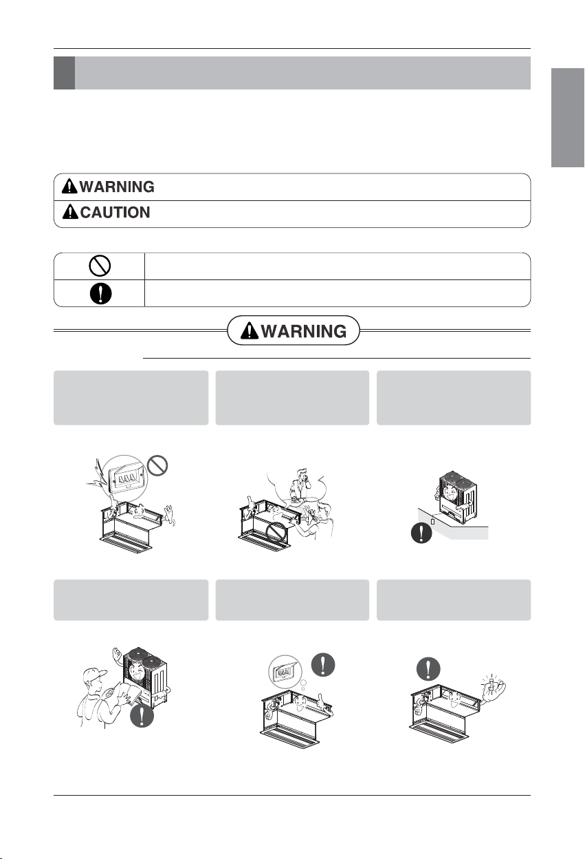
This symbol indicates the possibility of death or serious injury.
This symbol indicates the possibility of injury or damage to properties only.
Be sure not to do.
Be sure to follow the instruction.
■ Installation
Do not use a defective or underrated circuit breaker. Use this
appliance on a dedicated circuit.
• There is risk of fire or electric shock.
For electrical work, contact the
dealer, seller, a qualified electrician, or an Authorized Service
Center.
• Do not disassemble or repair the
product. There is risk of fire or electric shock.
Always ground the product.
• There is risk of fire or electric shock.
Install the panel and the cover
of control box securely.
• There is risk of fire or electric shock.
Always install a dedicated circuit and breaker.
• Improper wiring or installation may
cause fire or electric shock.
Use the correctly rated breaker
or fuse.
• There is risk of fire or electric shock.
4 Indoor Unit
Safety Precautions
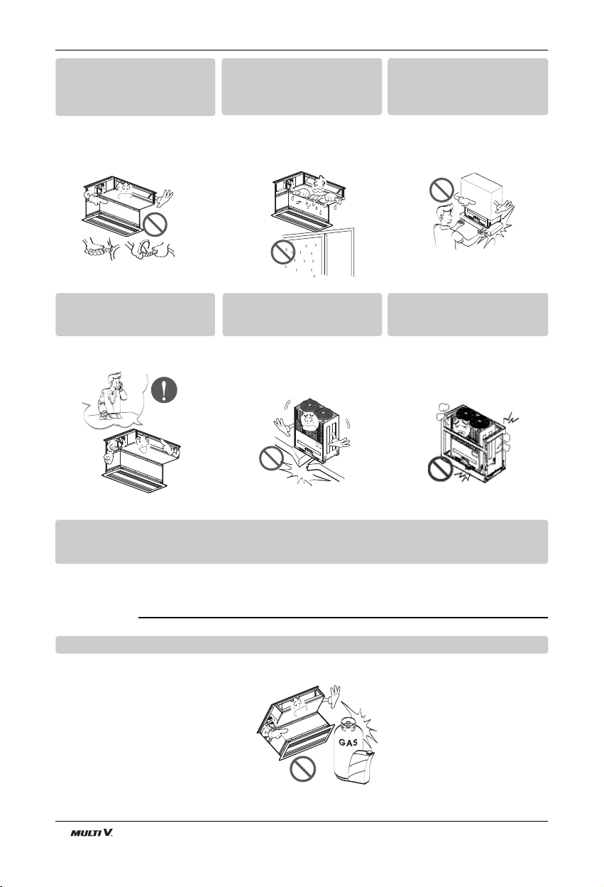
■ Operation
Do not modify or extend the
power cable.
• There is risk of fire or electric shock.
Do not let the air conditioner
run for a long time when the
humidity is very high and a door
or a window is left open.
• Moisture may condense and wet or
damage furniture.
Be cautious when unpacking
and installing the product.
• Sharp edges could cause injury. Be
especially careful of the case edges
and the fins on the condenser and
evaporator.
For installation, always contact
the dealer or an Authorized
Service Center.
• There is risk of fire, electric shock,
explosion, or injury.
Do not install the product on a
defective installation stand.
• It may cause injury, accident, or
damage to the product.
Be sure the installation area
does not deteriorate with age.
• If the base collapses, the air conditioner could fall with it, causing property damage, product failure, and
personal injury.
Do not store or use flammable gas or combustibles near the product.
• There is risk of fire or failure of product.
Use a vacuum pump or Inert (nitrogen) gas when doing leakage test or air purge.
Do not compress air or Oxygen and Do not use Flammable gases.
Otherwise, it may cause fire or explosion.
• There is the risk of death, injury, fire or explosion.
Gasolin
ENGLISH
Installation Manual 5
Safety Precautions
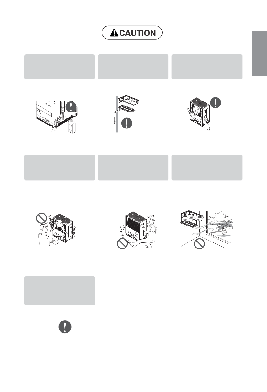
Always check for gas (refrigerant) leakage after installation or
repair of product.
• Low refrigerant levels may cause
failure of product.
Install the drain hose to ensure
that water is drained away properly.
• A bad connection may cause water
leakage.
Keep level even when installing
the product.
• To avoid vibration or water leakage.
Do not install the product where
the noise or hot air from the outdoor unit could damage the
neighborhoods.
• It may cause a problem for your
neighbors.
Use two or more people to lift
and transport the product.
• Avoid personal injury.
Do not install the product where
it will be exposed to sea wind
(salt spray) directly.
• It may cause corrosion on the product.
Corrosion, particularly on the condenser and evaporator fins, could
cause product malfunction or inefficient
operation.
■ Installation
If you eat the liquid from the
batteries, brush your teeth and
see doctor. Do not use the
remote if the batteries have
leaked.
• The chemicals in batteries could
cause burns or other health
hazards.
90˚
6 Indoor Unit
Introduction
Introduction
Wired Remote Controller
Wired Remote Controller
R
e
m
o
t
e
C
o
n
t
r
o
l
l
e
r
T
E
M
P
R
e
m
o
t
e
C
o
n
t
r
o
l
l
e
r
T
E
M
P
This symbol alerts you to the risk of electric shock.
This symbol alerts you to hazards that could cause harm to the
air conditioner.
This symbol indicates special notes.
NOTICE
Symbols Used in this Manual
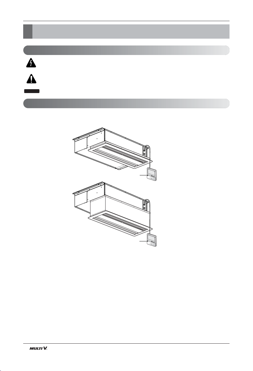
Features
Built-in Duct type
Suction Grille
Suction Grille + Suction Canvas
ENGLISH
Installation Manual 7
Installation
Installation
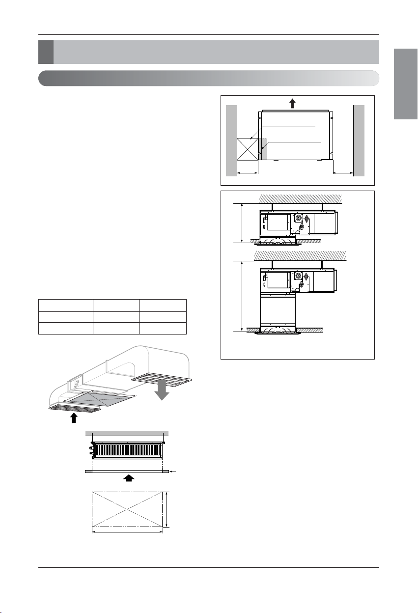
Indoor unit
Install the air conditioner in the location that satisfies the following conditions.
• The place shall easily bear a load exceeding four times the
indoor unitʼs weight.
• The place shall be able to inspect the unit as the figure.
• The place where the unit shall be leveled.
• The place shall easily connect with the outdoor unit.
• The place where the unit is not affected by an electrical
noise.
• The place where air circulation in the room will be good .
• There should not be any heat source or steam near the
unit
Confirm the positional relationship between the unit and
suspension bolts.
• Installation the ceiling opening to clean the filter or service
under the product.
Selection of the best location
• Refer to Suction grille and Suction canvas installation
manual for detail installation of Built-in duct type
270 or more520 or more
A(Min)
B(Min)
Ceiling
Service Space
A
B
Inspection hole
(600 x 600)
Control box
600600
Capacity(Btu/h) A B
7/9/12/15k 600 900
18/24k 600 1100
(Length: mm)
Built-in Duct type
8 Indoor Unit8 Indoor Unit
Installation
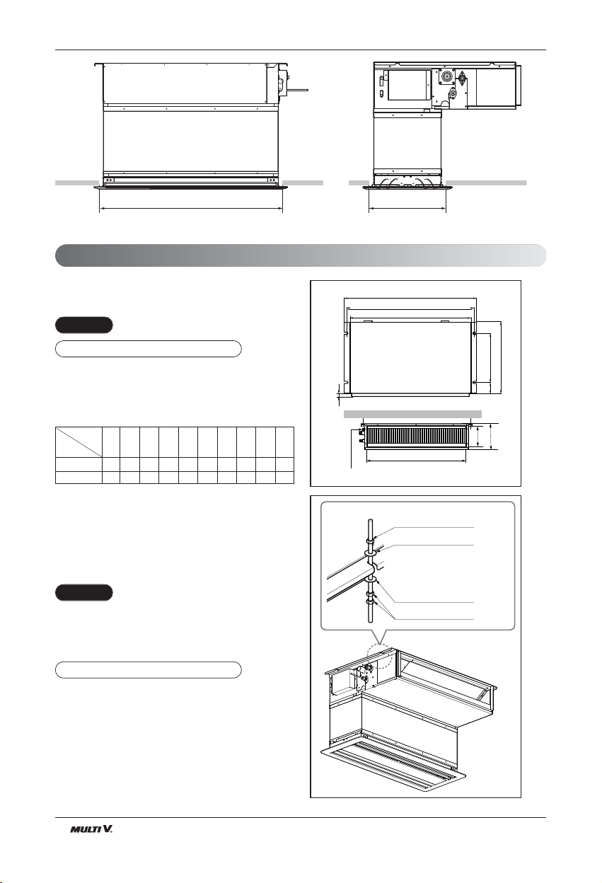
Ceiling dimension and hanging bolt location
Installation of Unit
Install the unit above the ceiling correctly.
• Apply a joint-canvas between the unit and duct to absorb
unnecessary vibration.
• Apply a filter Accessory at air return hole.
• Install the unit leaning to a drainage hole side as a figure
for easy water drainage.
• A place where the unit will be leveled and that can support
the weight of the unit.
• A place where the unit can withstand its vibration.
• A place where service can be easily performed.
CASE 1
POSITION OF SUSPENSION BOLT
(Unit:mm)
7/9/12/15k BTU/h
850 900 383 575 93 190 21 795 163 820
18/24k BTU/h
1130 1180 383 575 93 190 21 1065 163 1100
Dimension
Capacity(Btu/h)
ABCDEFGHI J
CE
G
D
A
J
B
M10 Nut
M10 washer
X 4
X 4
M10 Nut
M10 washer
X 4
X 8
I
F
H
Drainage hole
Drain Pump use
CASE 2
POSITION OF CONSOLE BOLT
B3/B4: 295
(Ceiling opening)
B4: 1118
B3: 840
(Ceiling opening)
ENGLISH
Installation Manual 9
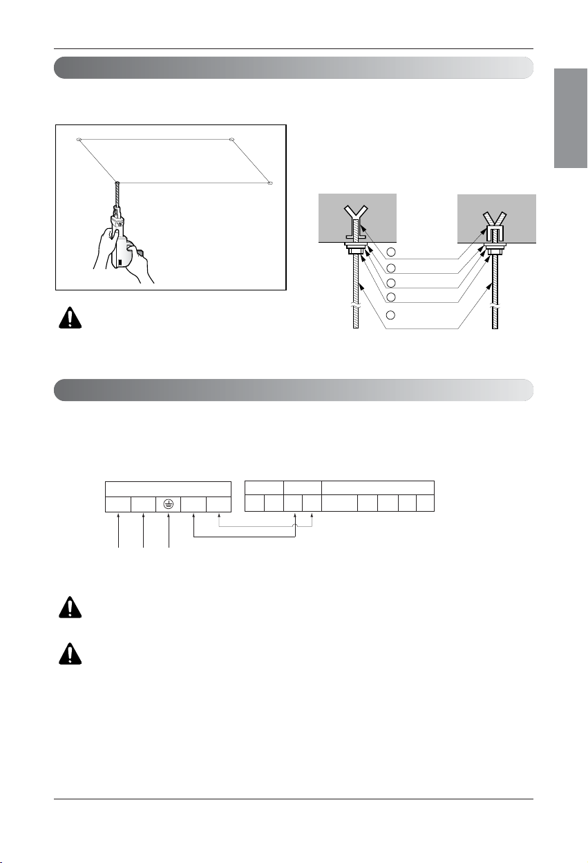
Installation
• Select and mark the position for fixing bolts.
• Drill the hole for set anchor on the face of ceiling.
• Insert the set anchor and washer onto the suspension bolts for locking the suspension bolts on the
ceiling.
•
Mount the suspension bolts to the set anchor firmly.
• Secure the installation plates onto the suspension
bolts (adjust level roughly) using nuts, washers
and spring washers.
1 Set anchor
Old building New building
2 Plate washer
3 Spring washer
4 Nut
5 Suspension�
bolts
Connect the wires to the terminals on the control board individually according to the outdoor unit connection.
• Ensure that the color of the wires of outdoor unit and the terminal No. are the same as those of indoor unit respectively.
Terminal Block Indoor
1(L) 2(N) 3 4
INDOOR POWER INPUT
IDU IDU
Outdoor unit
Indoor unit
Central controller
SODU SODU
DRY1
DRY2
GND
INTERNET
12V
Outdoor unit�
�
Wiring Connection
Indoor Unit Installation
CAUTION : Tighten the nut and bolt
to prevent unit falling.
WARNING : Make sure that the screws of the terminal are free from looseness.
B3/B4 Series
CAUTION : The Power cord connected to the unit should be selected according
to the following specifications.
 Loading...