

Page 1

INSTALLATION MANUAL
AIR CONDITIONER
• Please read this installation manual completely before installing the product.
• Installation work must be performed in accordance with the national wiring
standards by authorized personnel only.
• Please retain this installation manual for future reference after reading it
thoroughly.
P/NO : MFL42803109
www.lg.com
TYPE : Ceiling Concealed Duct - Low Static
ENGLISH
ITALIANO
ESPAÑOL
FRANÇAIS DEUTSCH
PORTUGUÊS
кмллдавьбхд
Page 2
2 Indoor Unit
Ceiling Concealed Duct - Low Static Type Indoor Unit Installation Manual
TABLE OF CONTENTS
❏ Four type "A" screws
❏ Connecting cable
❏ Pipes: Gas side
Liquid side
(Refer to Product
Data)
❏ Insulation materials
❏ Additional drain pipe
❏ Level gauge
❏ Screw driver
❏ Electric drill
❏ Hole core drill
❏ Flaring tool set
❏ Specified torque wrenches
(different depending on model No.)
❏ Spanner .......Half union
❏ A glass of water
❏ Screw driver
❏ Hexagonal wrench
❏ Gas-leak detector
❏ Vacuum pump
❏ Gauge manifold
❏ Owner's manual
❏ Thermometer
Safety Precautions.................3
Introduction.............................6
Installation
Selection of the best location
................................................7
Ceiling opening dimension
and hanging bolt location ......8
Indoor Unit Installation...........9
Wiring Connection .................9
Part name and functions .....10
Checking the Drainage........11
Installation of Wired
Remote Controller ...............15
Name and function of wired
remote controller(Accessory)
...17
Dip Switch Setting ...............18
Group Control Setting..........19
How to Set E.S.P? ................24
Installation Requirements
Required Parts Required Tools
Page 3
Installation Manual 3
ENGLISH
Safety Precautions
Safety Precautions
To prevent injury to the user or other people and property damage, the following instructions must be followed.
n Be sure to read before installing the air conditioner.
n Be sure to observe the cautions specified here as they include important items related to safety.
n Incorrect operation due to ignoring instruction will cause harm or damage. The seriousness is classified by the
following indications.
n Meanings of symbols used in this manual are as shown below.
This symbol indicates the possibility of death or serious injury.
This symbol indicates the possibility of injury or damage to properties only.
Be sure not to do.
Be sure to follow the instruction.
n Installation
Do not use a defective or
underrated circuit breaker.
Use this appliance on a dedicated circuit.
• There is risk of fire or electric
shock.
For electrical work, contact
the dealer, seller, a qualified
electrician, or an Authorized
Service Center.
• Do not disassemble or repair
the product. There is risk of
fire or electric shock.
Always ground the product.
• There is risk of fire or electric
shock.
Install the panel and the
cover of control box securely.
• There is risk of fire or electric
shock.
Always install a dedicated
circuit and breaker.
• Improper wiring or installation
may cause fire or electric
shock.
Use the correctly rated breaker or fuse.
• There is risk of fire or electric
shock.
Page 4
4 Indoor Unit
Safety Precautions
n Operation
Do not modify or extend the
power cable.
• There is risk of fire or electric
shock.
Do not let the air conditioner
run for a long time when the
humidity is very high and a
door or a window is left open.
• Moisture may condense and
wet or damage furniture.
Be cautious when unpacking
and installing the product.
• Sharp edges could cause
injury. Be especially careful of
the case edges and the fins
on the condenser and evaporator.
For installation, always contact the dealer or an
Authorized Service Center.
• There is risk of fire, electric
shock, explosion, or injury.
Do not install the product on
a defective installation stand.
• It may cause injury, accident,
or damage to the product.
Be sure the installation area
does not deteriorate with age.
• If the base collapses, the air
conditioner could fall with it,
causing property damage,
product failure, and personal
injury.
Do not store or use flammable gas or combustibles near the product.
• There is risk of fire or failure of product.
Use a vacuum pump or Inert (nitrogen) gas when doing leakage test or air purge.
Do not compress air or Oxygen and Do not use Flammable gases.
Otherwise, it may cause fire or explosion.
• There is the risk of death, injury, fire or explosion.
Page 5
ENGLISH
Installation Manual 5
Safety Precautions
n Installation
Always check for gas (refrigerant) leakage after installation or repair of product.
• Low refrigerant levels may
cause failure of product.
Install the drain hose to
ensure that water is drained
away properly.
• A bad connection may cause
water leakage.
Keep level even when
installing the product.
• To avoid vibration or water
leakage.
Do not install the product
where the noise or hot air from
the outdoor unit could damage the neighborhoods.
• It may cause a problem for
your neighbors.
Use two or more people to lift
and transport the product.
• Avoid personal injury.
Do not install the product
where it will be exposed to
sea wind (salt spray) directly.
• It may cause corrosion on the
product. Corrosion, particularly
on the condenser and evaporator fins, could cause product
malfunction or inefficient operation.
PTIf you eat the liquid from the batteries, brush your teeth and see doctor.
Do not use the remote if the batteries have leaked.
• The chemicals in batteries could cause burns or other health hazards.
Page 6
6 Indoor Unit
Introduction
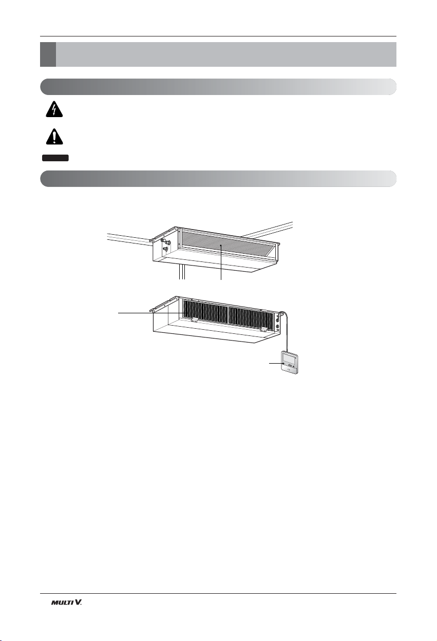
Introduction
Air outlet vents
Air filters
Wired Remote Controller
R
e
m
o
t
e
C
o
n
t
r
o
l
l
e
r
TEMP
This symbol alerts you to the risk of electric shock.
This symbol alerts you to hazards that could cause harm to the
air conditioner.
This symbol indicates special notes.
NOTICE
Symbols Used in this Manual
Features
Low static Duct type
Page 7
ENGLISH
Installation Manual 7
Installation
Installation
Indoor unit
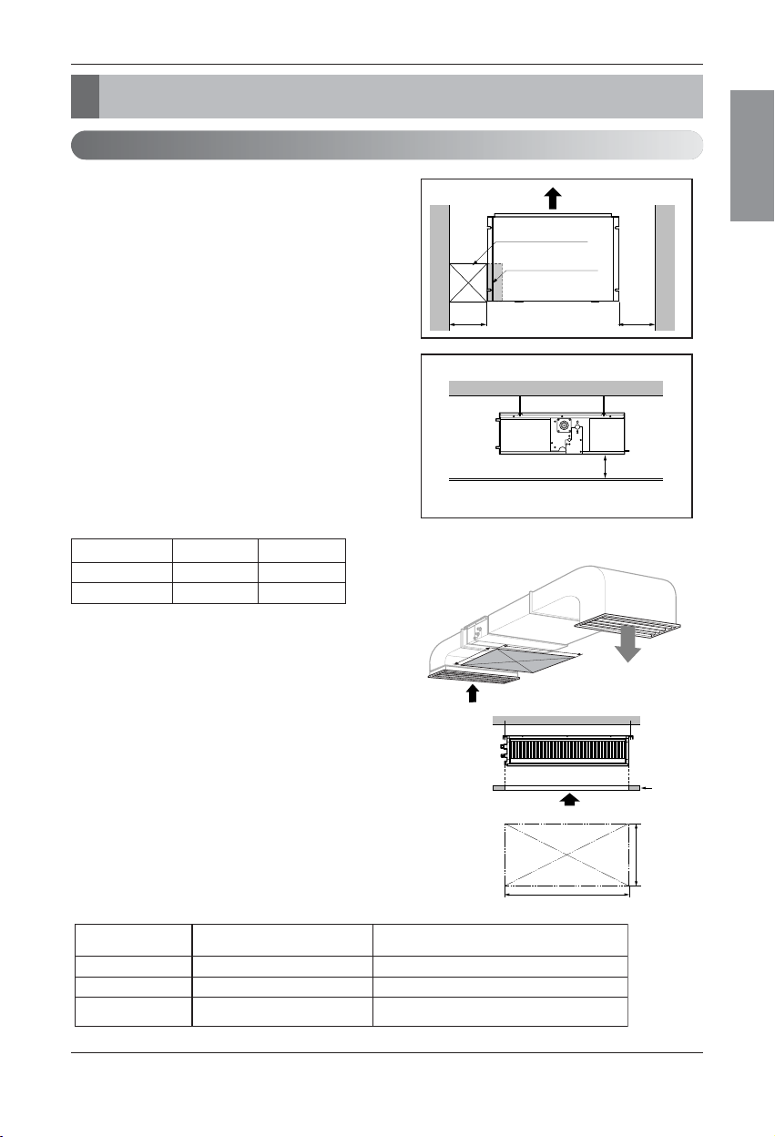
Install the air conditioner in the location that satisfies the following conditions.
• The place shall easily bear a load exceeding four times the
indoor unitʼs weight.
• The place shall be able to inspect the unit as the figure.
• The place where the unit shall be leveled.
• The place shall easily connect with the outdoor unit.
• The place where the unit is not affected by an electrical
noise.
• The place where air circulation in the room will be good .
• There should not be any heat source or steam near the
unit
Confirm the positional relationship between the unit and
suspension bolts.
• Installation the ceiling opening to clean the filter or service
under the product.
Selection of the best location
Inspection hole
(600 x 600)
Control box
H=20 or more
• Suitable dimension "H" is necessary to get a slooe
to drain as aiven in the fiaure
Side view
(unit: mm)
600600
A(Min)
B(Min)
Ceiling
Service Space
A
B
Capacity(Btu/h) A B
7/9/12/15k 600 900
18/24k 600 1100
(Length: mm)
Low static Duct type
Minimum height for motor replacement.
Less than 20cm
Hole size should be
more than the size of IDU.
Insufficient space. Difficult for servicing
20cm to 100cm2
Sufficient space in the ceiling for servicing.
More than 100cm1
Remarks
Distance between
False ceiling & Actual ceiling
Number of
Inspection hole
[Inspection Hole Standard]
Page 8
8 Indoor Unit
Installation
Ceiling dimension and hanging bolt location
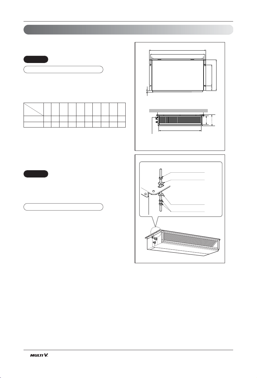
Installation of Unit
Install the unit above the ceiling correctly.
• Apply a joint-canvas between the unit and duct to absorb
unnecessary vibration.
• Apply a filter Accessory at air return hole.
• Install the unit leaning to a drainage hole side as a figure
for easy water drainage.
• A place where the unit will be leveled and that can support
the weight of the unit.
• A place where the unit can withstand its vibration.
• A place where service can be easily performed.
CASE 1
POSITION OF SUSPENSION BOLT
(Unit:mm)
7/9/12/15k BTU/h
850 900 383 575 93 190 21 795 163 820
18/24k BTU/h
1130 1180 383 575 93 190 21 1065 163 1100
Dimension
Capacity(Btu/h)
ABCDEFGHI J
CE
G
D
A
J
B
I
F
H
Drainage hole
Drain Pump use
M10 Nut
M10 washer
X 4
X 4
M10 Nut
M10 washer
X 4
X 8
CASE 2
POSITION OF CONSOLE BOLT
Page 9
ENGLISH
Installation Manual 9
Installation
• Select and mark the position for fixing bolts.
• Drill the hole for set anchor on the face of ceiling.
• Insert the set anchor and washer onto the suspension bolts for locking the suspension bolts on the
ceiling.
•
Mount the suspension bolts to the set anchor firmly.
• Secure the installation plates onto the suspension
bolts (adjust level roughly) using nuts, washers
and spring washers.
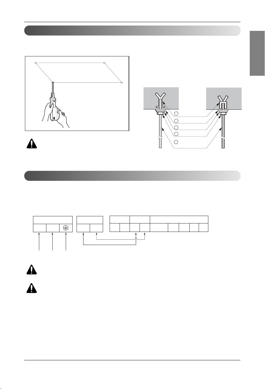
Connect the wires to the terminals on the control board individually according to the outdoor unit connection.
• Ensure that the color of the wires of outdoor unit and the terminal No. are the same as those of indoor unit respectively.
Wiring Connection
Indoor Unit Installation
CAUTION : Tighten the nut and bolt
to prevent unit falling.
B1/B2 Series
WARNING : Make sure that the screws of the terminal are free from looseness.
CAUTION : The Power cord connected to the unit should be selected according
to the following specifications.
Old building New building
1 Set anchor
2 Plate washer
3 Spring washer
4 Nut
5 Suspension
bolts
Terminal Block Indoor
INDOOR POWER INPUT
Terminal Block Indoor
34L(L1) N(L2)
Outdoor unit
SODU SODU
Indoor unit
IDU IDU
Central controller
INTERNET
DRY1
DRY2
GND
12V
Outdoor unit
Page 10

10 Indoor Unit
Installation
• Low static duct type in case of suction from back
side.
• Low static duct type in case of suction from bottom
side.
Air Filter
Air outlet
Panel Rear
Air outlet
Air Filter
Panel Rear
Part name and functions
Page 11

ENGLISH
Installation Manual 11
Installation
1. Remove the Air Filter.
2. Check the drainage.
• Spray one or two glasses of water upon the
evaporator.
• Ensure that water flows drain hose of indoor
unit without any leakage.
Checking the Drainage
INSULATION, OTHERS
Insulate the joint and tubes completely.
All thermal insulation must comply with local requirement.
INDOOR UNIT
■ After all workings are finished, check the working and operation.
• Air distribution ............... Is the air circulation good?
• Drain ............................. Is the drainage smoothly and no sweating?
• Gas leakage ................. Is the piping connection correctly?
• Wiring ........................... Is the wiring connection correctly?
• Lock-bolt ....................... Is the lock-bolt of compressor loosened?
• Insulation Is the unit fully insulated?
• Ground Is the unit safely grounded?
THERMAL INSULATION
TEST AND CHECK
Make sure that there is no clearance here.
Overlap with thermal
insulator for piping.
Thermal insulator for refrigerant pipe
(Local supply)
Thermal insulator for
piping(Local supply)
Hose clip for thermal insulator(Local supply)
Union for gas pipe
Refrigerant pipe and thermal
insulator(Local supply)
Union for liquid pipe
Thermal insulator for refrigerant pipe
(Local supply)
Hose clip for thermal insulator
(Local supply)
Felt
Rubber
Insulation
No clearance
Cabinet
Page 12

12 Indoor Unit
Installation
CAUTION
Ceiling
Drain Pump use
Drainage hole
Front of view
1. Install declination of the indoor unit is very important for the drain of the duct type air conditioner.
2. Minimum thickness of the insulation for the connecting pipe shall be 19mm.
• The unit must be horizontal or declined to the drain hose connected when finished
installation.
• Drain piping must have down-slope (1/50 to 1/100): be sure not to
provide up-and-down slope to prevent reversal flow.
• During drain piping connection, be careful not to exert extra force
on the drain port on the indoor unit.
• The outside diameter of the drain connection on the indoor unit is
32mm.
•
Be sure to install heat insulation on the drain piping.
Piping material: Polyvinyl chloride pipe VP-25 and
pipe fittings
The air conditioner uses a drain pump to drain water.
Use the following procedure to test the drain pump operation:
• Connect the main drain pipe to the exterior
and leave it provisionally until the test
comes to an end.
• Feed water to the flexible drain hose and
check the piping for leakage.
• Be sure to check the drain pump for normal
operating and noise when electrical wiring
is complete.
• When the test is complete, connect the
flexible drain hose to the drain port on the
indoor unit.
Heat insulation material: Polyethylene foam with thickness more than 8 mm.
Drain test
Upward
routing
not allowed
Pipe clamp
Maintenance
drain port
Indoor unit
Feed water
Drain Pump
Drain pan
Flexible drain hose
Main
drain pipe
Glue the joint
Drain
port
Drain hose connection
Use the clip
Drain Piping
Page 13

Installation Manual 13
ENGLISH
Installation
CAUTION:
After the confirmation of the above conditions, prepare the wiring as follows:
1) Never fail to have an individual power specialized for the air conditioner. As for the method of
wiring, be guided by the circuit diagram posted on the inside of control box cover.
2) Provide a circuit breaker switch between power source and the unit.
3) The screws which fasten the wiring in the casing of electrical fittings are liable to come loose
from vibrations to which the unit is subjected during the course of transportation. Check them
and make sure that they are all tightly fastened. (If they are loose, it could give rise to burn-out
of the wires.)
4) Specification of power source
5) Confirm that electrical capacity is sufficient.
6) Be sure that the starting voltage is maintained at more than 90 percent of the rated voltage
marked on the name plate.
7) Confirm that the cable thickness is as specified in the power sources specification.
(Particularly note the relation between cable length and thickness.)
8) Never fail to equip a leakage breaker where it is wet or moist.
9) The following troubles would be caused by voltage drop-down.
• Vibration of a magnetic switch, damage on the contact point, fuse breaking, disturbance by the nor-
mal function of an overload protection device.
• Proper starting power is not given to the compressor.
HAND OVER
Teach the customer the operation and maintenance procedures, using the operation manual.
(air filter cleaning, temperature control, etc.)
1/50~1/100 slope
Hanger
distance
Hanger Bracket
Max 700mm
Flexible drain hose
Insulation
Metal
clamp
Max 300mm
1~15m
CAUTION : The supplied flexible drain
hose should not be curved, neither
screwed. The curved or screwed hose
may cause a leakage of water.
4 EA
Name
Quantity
Shape
for gas pipe
for liquid pipe
Clamp metal
2 EA
Insulation for
fitting
1 SET
Drain hose
1 EA
Clamp
(Tie Wrap)
8 EA
Washer for
hanging backet
(Other)
Standard Accessories
• Owner's manual
• Installation manual
Page 14

14 Indoor Unit
WIERED REMOTE CONTROLLER INSTALLATION
• Since the room temperature sensor is in the remote controller, the remote controller box should be installed in a place
away from direct sunlight, high humidity and direct supply of cold air to maintain proper space temperature.
Install the remote controller about 5ft(1.5m) above the floor in an area with good air circulation at an average temperature.
Do not install the remote controller where it can be affected by:
- Drafts, or dead spots behind doors and in corners.
- Hot or cold air from ducts.
- Radiant heat from sun or appliances.
- Concealed pipes and chimneys.
- Uncontrolled areas such as an outside wall behind the remote controller.
- This remote controller is equipped with a seven segment LED. display. For proper display of the remote controller
LED's, the remote controller should be installed properly as shown in Fig.1.
(The standard height is 1.2~1.5 m from floor level.)
R
e
m
o
t
e
C
o
n
t
r
o
l
l
e
r
T
E
M
P
5feet
(1.5meters)
no
no
no
yes
Remote Controller
TEMP
Remote Controller
TEMP
Fig.1 Typical locations for remote controller
Installation
Page 15

Installation Manual 15
Installation
ENGLISH
Installation of Wired Remote Controller
1. Please fix tightly using provided screw after placing remote controller setup board on the place where
you like to setup.
- Please set it up not to bend because poor setup could take place if setup board bends.
Please set up remote controller board fit to the reclamation box if there is a reclamation box.
2. Can set up Wired remote controller cable into three directions.
- Setup direction: the surface of wall reclamation, upper, right
- If setting up remote controller cable into upper and right side, please set up after removing remote controller
cable guide groove.
❈
Remove guide groove with long nose.
①
Reclamation to the surface of the wall
②
Upper part guide groove
③
Right part guide groove
Wall
Side
Wall
Side
Wall
Side
Wall
Side
<Connecting order>
<Separating order>
3. Please fix remote controller upper part into the
setup board attached to the surface of the wall, as
the picture below, and then, connect with setup
board by pressing lower part.
- Please connect not to make a gap at the remote controller and setup boardʼs upper and lower, right and left
part.
When separating remote controller from setup
board, as the picture below, after inserting into the
lower separating hole using screw driver and then,
spinning clockwise, remote controller is separated.
- There are two separating holes. Please individually
separate one at a time.
- Please be careful not to damage the inside
components when separating.
2
3
1
2
3
<Wire guide grooves>
Page 16

16 Indoor Unit
Installation
4. Please connect indoor unit and remote controller using connection cable.
5. Please use extension cable if the distance between wired remote controller and indoor unit is more
than 10m.
Please check if connector is normally connected.
Connecting cable
Indoor
Unit side
When installing the wired remote controller, do not bury it in the wall.
(It can cause damage in the temperature sensor.)
Do not install the cable to be 50m or above.
(It can cause communication error.)
• When installing the extension cable, check the connecting direction of the connector of the
remote controller side and the product side for correct installation.
• If you install the extension cable in the opposite direction, the connector will not be connected.
• Specification of extension cable: 2547 1007 22# 2 core 3 shield 5 or above.
Page 17

Installation Manual 17
Installation
ENGLISH
Name and function of wired remote controller(Accessory)
※ Some functions may not be operated and displayed depending on the product type.
※ It will display strange value to the room temperature if wired remote controller is not connected.
Model : PQRCVSL0 (Black Color)
PQRCVSL0QW (White Color)
1. Operation indication screen
2. Set temperature button
•
It will set not room temperature but outlet air temperature.
3. Fan speed button
• Fan Speed have 3 Steps.
• Middle and Low step is same
4. ON/OFF button
5. Opration mode selection button
6. Wireless remote controller receiver
• Some products don't receive the wireless signals.
7. Air flow button
8. Subfunction button
9. Function setting button
10. Ventilation button
11. Reservation
12. Up,down,left,right button
• To check the indoor temperature, press button.
13. Room temperature button
• Displays only the room temperature of the remote
controller perception.
• There is no control of room temperature.
• In case of fresh air intake unit, displays only the
temperature around remote controller.
14. Setting/Cancel button
15. Exit button
1
10
9
8
7
11
12
13
14
15
2
3
4
5
6
Please attach the inform label inside of the door.
Please choose proper language depend on your
country.
Page 18

18 Indoor Unit
Installation
Dip Switch Setting
For Multi V Models, Dip switch 1, 2, 6, 8 must be set OFF.
Function Description Setting Off Setting On Default
SW1
SW2
SW3
SW4
SW5
SW6
SW7
SW8
Communication
Cycle
Group Control
Dry Contact Mode
Installation
Heater linkage
Ventilator linkage
Vane selection
(Console)
Region selection
Etc.
N/A (Default)
N/A (Default)
Selection of Master or Slave
Selection of Dry Contact
Mode
Fan continuous operation
N/A
Selection of Ventilator link-
age
Selection of up/down side
Vane
Selection tropical region
Spare
-
-
Master
Wired/Wireless remote
controller
Selection of Manual or Auto
operation Mode
Continuous operation Removall
-
Linkage Removal
Up side + Down side Vane
General model
-
-
-
Slave
Auto
-
-
Working
Up side Vane
Only
Tropical model
-
Off
Off
Off
Off
Off
Off
Off
Off
Page 19

Installation Manual 19
Installation
ENGLISH
Group Control Setting
Wired remote controller 1 + Standard Indoor Units
Dip Switch in PCB (Cassette and Duct Type indoor units)
1. It is possible to 16 indoor units(Max) by one wired remote controller.
Set only one indoor unit to Master, set the others to Slave.
2. It is possible to connect with every type of indoor units.
3. It is possible to use wireless remote controller at the same time.
4. It is possible to connect with Dry Contact and Central controller at the same time.
GND
Signal
12 V
Master
Slave
Slave
Slave
Master
Display Error Message
Only connect serial signal and GND lines
between slave indoor unit
LGAP Network System
- No. 3 Off - No. 3 On
- The Master indoor unit is possible to recognize Dry Contact and Central Controller only.
- In case of Central controller and Group controller at the same time, it is possible to connect
standard 2series indoor units or later since Feb. 2009.
- In case of Central controller setting, the Central controller can control indoor units after
setting only the address of master indoor unit.
- Slave indoor unit will be operated like master indoor unit.
- Slave indoor unit can not be individually controlled by Central controller.
- Some remote controller can’t perform with Dry Contact and Central controller at the same
time. So contact us further information about it.
1. Group Control 1
Page 20

20 Indoor Unit
Installation
2. Group Control 2
5. In case of any error occurs at indoor unit, display on the wired remote controller.
Exception of the error indoor unit, an individual indoor unit control possibility.
6. In case of Group Control, it is possible to use following functions.
- Selection of operation options (operation/stop/mode/set temperature)
- Control of flow rate (High/Middle/Low)
- It is not possible at some functions.
Master/Slave setting of indoor units be set possible using a PCB Dip Switch.
It is possible to connect indoor units since Feb. 2009.
In the other cases, please contact LGE.
It can be the cause of malfuctions when there is no setting of master and slave.
2. Group Control 2
Wired remote controllers + Standard Indoor Units
LGAP Network System
Master
Master
Slave
Donʼt connect serial 12V line
Display Error Message
Slave
Slave
Slave
GND
Signal
12 V
It is possible to control N indoor units by wired remote controller M units. (M+N≤17 Units)
Set only one indoor unit to Master, set the others to Slave.
Set only one wired remote controller to Master, set the others to Slave.
Other than those, it is same with the Group Control 1.
Page 21

Installation Manual 21
Installation
ENGLISH
Mixture connection with indoor units and Fresh Air Intake Unit
In case of connecting with standard indoor unit and Fresh Intake Unit, separate Fresh Air Intake
Unit with standard units.
(Because setting temperature are different.)
Other than those, it is same with Group Control 1.
GND
Signal
12 V
LGAP Network System
Display Error Message
FAU
Master
FAU
Slave
Master
Master
Master
Slave
FAU
Standard Standard
FAU FAU
Standard Standard
FAU
* FAU : Fresh Air Intake Unit
Standard: Standard Indoor Unit
3. Group Control 3
Page 22

22 Indoor Unit
Installation
Wired remote controller 2 + Indoor unit 1
1. It is possible to connect two wired remote controllers with one indoor unit.
2. Every types of indoor unit is possible to connect two remote controller.
3. It is possible to use wireless remote controller at the same time.
4. It is possible to connect with Dry Contact and Central controller at the same time.
5. In case of any error occurs at indoor unit, display on the wired remote controller.
6. There isnʼt limits of indoor unit function.
LGAP Network System
Display Error Message
Master
Master
Slave
❈ Maximum 2wired remote controllers can be connected with 1 indoor unit.
4. 2 Remote Control
Page 23

Installation Manual 23
Installation
ENGLISH
Slave
Mas te r
Mas ter
PZCWRCG3
Mas ter S lave
PZCWRC2
Indoor unit 2 EA +Wired remote controller
❈ PZCWRCG3 cable used for connection ❈ PZCWRC2 cable used for connection
Indoor unit 1 EA +Wired remote controller 2EA
It is possible to set group control by using below accessories.
5. Accessories for group control setting
Page 24

24 Indoor Unit
How to Set E.S.P?
How to Set E.S.P?
• If you set ESP incorrectly, the air conditioner may malfunction.
• This setting must be carried out by a certificated-technician.
This is the function that decides the strength of the wind for each wind level and because this function is
to make the installation easier.
•
When setting ESP value on the product without very weak wind or power wind function, it may not
work.
If pressing button long for 3
1
seconds, it enters into remote
controller setter setup mode.
- If pressing once shortly, it enters
into user setup mode. Please press
more than 3 seconds for sure.
If entering into ESP setup mode by using
2
button, it indicates as the picture
below.
ESP step
Function Code ESP value
Function code,
ESP code
ESP value
Select ESP fan step by pressing
3
button. (01: very low, 02: low, 03:
medium, 04: high, 05: power)
Move to ESP value setting by pressing
4
button.
(It is 000 when delivering
from the warehouse.)
Press button to setup ESP value.
5
(It is possible to setup ESP
value from 1 to 255, and 1 is
the smallest and 255 is the
biggest.)
Page 25

Installation Manual 25
ENGLISH
How to Set E.S.P?
• Please be careful not to change the ESP value for each fan step.
• It does not work to setup ESP value for very low/power step for some products.
• ESP value is available for specific range belongs to the product.
Select ESP fan step again by using
6
button and setup ESP value, as No. 4
and 5, that corresponds each wind flow
Press button to save.
7
Press button to exit.
8
❈ After setup, it automatically gets out of
setup mode if there is no button input
for 25 seconds.
Function code,
ESP code
ESP value
❈ When exiting without pressing set
button, the manipulated value is not
reflected.
Page 26

26 Indoor Unit
How to Set E.S.P?
Note :
1. The above table shows the correlation between the air rates and E.S.P.
Setting Value
60 6.02 2.25 0.61 - 65 6.95 3.32 0.73 0.54 0.48
70 7.69 5.16 1.19 0.65 0.56
75 8.46 6.93 2.42 0.77 0.63
80 9.5 7.37 3.4 0.87 0.72
85 10.35 8.72 5.33 1.35 0.88
90 10.81 9.66 6.75 3.15 0.98
95 11.57 10.31 8.56 4.73 1.03
100 12.58 11.22 9.75 7.46 2.31
105 13.31 12.27 10.89 8.64 5.01
110 14.2 13.24 12.15 10.49 7.7
115 14.82 13.92 12.64 11.16 9.48
0(0) 1(10) 2(20) 3(30) 4(40)
Static Pressure(mmAq(Pa))
Setting Value
65 10.07 6.9 0.82 - -
70 11.39 8.49 2.2 - -
75 12.01 9.79 4.2 - -
80 13.21 11.03 5.92 0.92 -
85 14.24 12.36 9.41 2.1 -
90 15.04 13.34 10.8 5.29 1.01
95 16.02 14.63 12.5 7.59 1.34
100 17.11 15.56 13.66 11.53 5.35
105 17.99 16.53 15.17 12.35 7.67
110 19.04 17.71 16.22 14.23 10.45
115 19.77 18.62 17.1 15.23 13.25
120 20.94 19.92 18.56 16.98 14.66
125 21.97 20.56 19.25 17.68 16.06
130 22.83 21.98 20.75 19.32 17.73
0(0) 1(10) 2(20) 3(30) 4(40)
Static Pressure(mmAq(Pa))
ARNU07GB1G2, ARNU09GB1G2, ARNU12GB1G2, ARNU15GB1G2
ARNU18GB2G2, ARNU24GB2G2
(Unit: CMM)
(Unit: CMM)
Page 27

 Loading...