

Page 1
INSTALLATION MANUAL
РУССКИЙ ЯЗЫК
ENGLISH
УКРАÏНСЬКА
ITALIANO
ҚАЗАҚ ТІЛІ
ESPAÑOL
БЕЛАРУСКАЯ МОВА
FRANÇAIS
AIR
CONDITIONER
Please read this installation manual completely before installing the product.
Installation work must be performed in accordance with the national wiring standards by
authorized personnel only.
Please retain this installation manual for future reference after reading it thoroughly.
Convertible
Original instruction
[Representative] LG Electronics Inc. EU Representative : LG Electronics European Shared
Service Center B.V. Krijgsman 1, 1186 DM Amstelveen, The Netherlands
[Manufacturer] LG Electronics Inc. Changwon 2nd factory 84, Wanam-ro, Seongsan-gu,
Changwon-si, Gyeongsangnam-do, KOREA
O‘ZBEK TILI
DEUTSCH
ΕΛΛΗΝΙΚΆ
ČEŠTINA
NEDERLANDS
POLSKI
LIMBA ROMÂNĂ
MFL68800312
Rev.00_052319
www.lg.com
Copyright © 2017 - 2019 LG Electronics Inc. All Rights Reserved.
Page 2
Table of Contents
TABLE OF CONTENTS
3 SAFETY PRECAUTIONS
9 INTRODUCTION
9 Symbols used in this Manual
9 Features
10 INSTALLATION
10 Installation Parts
10 Installation Tools
12 Wired remote controller installation
13 Installation Map
14 Select the best Location
14 Preparing Work for Installation
15 Mounting the installation plate(Wall Mounting)
15 Mounting the anchor Nut & Bolt(Ceiling Mounting)
17 Checking the Drainage
17 Panel Front Assembly
18 Flaring Work
19 Drill a Hole in the Wall
19 Connecting the Piping
21 Precautions when laying power wiring
21 Wiring Connection
23 DIP Switch Setting
24 Group Control Setting
29 Model Designation
29 Airborne Noise Emission
29 Limiting concentration
2 Indoor Unit
Page 3
Safety Precautions
The following symbols are displayed on indoor and outdoor units.
Safety Precautions
ENGLISH
Read the precautions in this manual
carefully before operating the unit.
This symbol indicates that the Operation
Manual should be read carefully.
To prevent injury to the user or other people and property damage, the following instructions must
be followed.
n Incorrect operation due to ignoring instruction will cause harm or damage. The seriousness is
classified by the following indications.
WARNING
!
!
CAUTION
n Meanings of symbols used in this manual are as shown below.
This symbol indicates the possibility of death or serious injury.
This symbol indicates the possibility of injury or damage to properties only.
Be sure not to do.
Be sure to follow the instruction.
!
WARNING
This appliance is filled with flammable
refrigerant (R32)
This symbol indicates that a service
personnel should be handling this
equipment with reference to the
Installation Manual.
Installation
• Compliance with national gas regulations shall be observed.
• Do not use a defective or underrated circuit breaker. Use this appliance on a
dedicated circuit.
- There is risk of fire or electric shock.
• For electrical work, contact the dealer, seller, a qualified electrician, or an Authorized
Service Center.
- Do not disassemble or repair the product. There is risk of fire or electric shock.
• Always ground the product.
- There is risk of fire or electric shock.
• Install the panel and the cover of control box securely.
- There is risk of fire or electric shock.
Installation Manual 3
Page 4

Safety Precautions
• Always install a dedicated circuit and breaker.
- Improper wiring or installation may cause fire or electric shock.
• Use the correctly rated breaker or fuse.
- There is risk of fire or electric shock.
• Do not modify or extend the power cable.
- There is risk of fire or electric shock.
• Do not install, remove, or re-install the unit by yourself (customer).
- There is risk of fire, electric shock, explosion, or injury.
• Be cautious when unpacking and installing the product.
- Sharp edges could cause injury. Be especially careful of the case edges and the fins
on the condenser and evaporator.
• For installation, always contact the dealer or an Authorized Service Center.
- There is risk of fire, electric shock, explosion, or injury.
• Do not install the product on a defective installation stand.
- It may cause injury, accident, or damage to the product.
• Be sure the installation area does not deteriorate with age.
- If the base collapses, the air conditioner could fall with it, causing property damage,
product failure, and personal injury.
• Do not turn on the breaker or power under condition that front panel, cabinet, top
cover, control box cover are removed or opened.
- Otherwise, it may cause fire, electric shock, explosion or death.
• Use a vacuum pump or Inert (nitrogen) gas when doing leakage test or air purge. Do
not compress air or Oxygen and Do not use Flammable gases. Otherwise, it may
cause fire or explosion.
- There is the risk of death, injury, fire or explosion.
• Have all electric work done by a licensed electrician according to "Electric Facility
Engineering Standard" and "Interior Wire Regulations" and the instructions given in
this manual and always use a special circuit.
- If the power source capacity is inadequate or electric work is performed improperly,
electric shock or fire may result.
• Always intstall a dedicated circuit and breaker.
- Improper wiring or installation may cause fire or electric shock.
• The appliance shall be stored in a well-ventilated area where the room size
corresponds to the room area as specified for operation. (for R32)
• The appliance shall be stored in a room without continuously operating ignition
sources (for example: open flames, an operating gas appliance or an operating
electric heater.)
4 Indoor Unit
Page 5

Safety Precautions
• Keep any required ventilation openings clear of obstruction.
ENGLISH
• Mechanical connections shall be accessible for maintenance purposes.
• To prevent the mixing of different types of refrigerants, be sure to check the type of
refrigerant used in the outdoor unit.
Operation
• Do not let the air conditioner run for a long time when the humidity is very high and a
door or a window is left open.
- Moisture may condense and wet or damage furniture.
• Take care to ensure that power cable could not be pulled out or damaged during
operation.
- There is risk of fire or electric shock.
• Do not place anything on the power cable.
- There is risk of fire or electric shock.
• Do not plug or unplug the power supply plug during operation.
- There is risk of fire or electric shock.
• Do not touch(operate) the product with wet hands.
- There is risk of fire or electrical shock.
• Do not place a heater or other appliances near the power cable.
- There is risk of fire and electric shock.
• Do not allow water to run into electric parts.
- There is risk of fire, failure of the product, or electric shock.
• Do not store or use flammable gas or combustibles near the product.
- There is risk of fire or failure of product.
• Do not use the product in a tightly closed space for a long time.
- Oxygen deficiency could occur.
• When flammable gas leaks, turn off the gas and open a window for ventilation before
turn the product on.
- Do not use the telephone or turn switches on or off. There is risk of explosion or fire.
• If strange sounds, smell or smoke comes from product. Turn the breaker off or
disconnect the power supply cable.
- There is risk of electric shock or fire.
• Stop operation and close the window in storm or hurricane.
If possible, remove the product from the window before the hurricane arrives.
- There is risk of property damage, failure of product, or electric shock.
Installation Manual 5
Page 6
Safety Precautions
• Do not open the inlet grill of the product during operation.
(Do not touch the electrostatic filter, if the unit is so equipped.)
- There is risk of physical injury, electric shock, or product failure.
• When the product is soaked (flooded or submerged), contact an Authorized Service
Center.
- There is risk of fire or electric shock.
• Be cautious that water could not enter the product.
- There is risk of fire, electric shock, or product damage.
• Ventilate the product from time to time when operating it together with a stove, etc.
- There is risk of fire or electric shock.
• Turn the main power off when cleaning or maintaining the product.
- There is risk of electric shock.
• When the product is not be used for a long time, disconnect the power supply plug or
turn off the breaker.
- There is risk of product damage or failure, or unintended operation.
• Take care to ensure that nobody could step on or fall onto the outdoor unit.
- This could result in personal injury and product damage.
• When mechanical connectors are reused indoors, sealing parts shall be renewed. (for
R32)
• When flared joints are reused indoors, the flare part shall be re-fabricated. (for R32)
• Periodic ( more than once/year ) cleaning of the dust or salt particles stuck on the heat
exchanger by using water.
• Do not use means to accelerate the defrosting process or to clean, other than those
recommended by the manufacturer.
• Do not pierce or burn refrigerant cycle part.
• Be aware that refrigerants may not contain an odour.
!
CAUTION
Installation
• Always check for gas (refrigerant) leakage after installation or repair of product.
- Low refrigerant levels may cause failure of product.
• Install the drain hose to ensure that water is drained away properly.
- A bad connection may cause water leakage.
• Keep level even when installing the product.
- To avoid vibration or water leakage.
6 Indoor Unit
Page 7

Safety Precautions
• Do not install the product where the noise or hot air from the outdoor unit could
ENGLISH
damage the neighborhoods.
- It may cause a problem for your neighbors.
• Use two or more people to lift and transport the product.
- Avoid personal injury.
• Do not install the product where it will be exposed to sea wind (salt spray) directly.
- It may cause corrosion on the product. Corrosion, particularly on the condenser and
evaporator fins, could cause product malfunction or inefficient operation.
• Any person who is involved with working on or breaking into a refrigerant circuit should
hold a current valid certificate from an industry-accredited assessment authority, which
authorises their competence to handle refrigerants safely in accordance with an
industry recognised assessment specification. (for R32)
• The appliance shall be stored so as to prevent mechanical damage from occurring.
• Refrigerant tubing shall be protected or enclosed to avoid damage.
• Flexible refrigerant connectors (such as connecting lines between the indoor and
outdoor unit) that may be displaced during normal operations shall be protected
against mechanical damage.
• The installation of pipe-work shall be kept to a minimum.
• Pipe-work shall be protected from physical damage.
• A brazed, welded, or mechanical connection shall be made before opening the valves
to permit refrigerant to flow between the refrigerating system parts.
• Dismantling the unit, treatment of the refrigerant oil and eventual parts should be done
in accordance with local and national standards.
Operation
• Do not expose the skin directly to cool air for long periods of time. (Don't sit in the
draft.)
- This could harm to your health.
• Do not use the product for special purposes, such as preserving foods, works of art,
etc. It is a consumer air conditioner, not a precision refrigeration system.
- There is risk of damage or loss of property.
• Do not block the inlet or outlet of air flow.
- It may cause product failure.
• Use a soft cloth to clean. Do not use harsh detergents, solvents, etc.
- There is risk of fire, electric shock, or damage to the plastic parts of the product.
Installation Manual 7
Page 8
Safety Precautions
• Do not touch the metal parts of the product when removing the air filter. They are very
sharp!
- There is risk of personal injury.
• Do not step on or put anything on the product. (outdoor units)
- There is risk of personal injury and failure of product.
• Always insert the filter securely. Clean the filter every two weeks or more often if
necessary.
- A dirty filter reduces the efficiency of the air conditioner and could cause product
malfunction or damage.
• Do not insert hands or other objects through the air inlet or outlet while the product is
operated.
- There are sharp and moving parts that could cause personal injury.
• Do not drink the water drained from the product.
- It is not sanitary and could cause serious health issues.
• Use a firm stool or ladder when cleaning or maintaining the product.
- Be careful and avoid personal injury.
• Replace the all batteries in the remote control with new ones of the same type. Do not
mix old and new batteries or different types of batteries.
- There is risk of fire or explosion.
• Do not recharge or disassemble the batteries. Do not dispose of batteries in a fire.
- They may burn or explode.
• If the liquid from the batteries gets onto your skin or clothes, wash it well with clean
water. Do not use the remote if the batteries have leaked.
- The chemicals in batteries could cause burns or other health hazards.
• If you eat the liquid from the batteries, brush your teeth and see doctor. Do not use the
remote if the batteries have leaked.
- The chemicals in batteries could cause burns or other health hazards.
• Servicing shall only be performed as recommended by the equipment manufacturer.
Maintenance and repair requiring the assistance of other skilled personnel shall be
carried out under the supervision of the person competent in the use of flammable
refrigerants. (for R32)
• Means for disconnection must be incorporated in the fixed wiring in accordance with
the wiring rules.
• If the supply cord is damaged, it must be replaced by the manufacturer, its service
agent or similarly qualified persons in order to avoid a hazard.
8 Indoor Unit
Page 9
NOTICE
Introduction
Symbols used in this Manual
This symbol alerts you to the risk of electric shock.
This symbol alerts you to hazards that may cause harm to the
air conditioner.
This symbol indicates special notes.
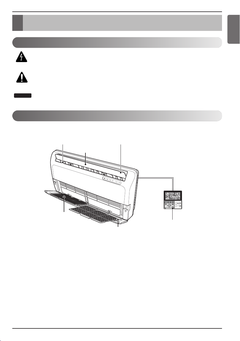
Features
Vertical louver Horizontal louver
Air outlet vent
Introduction
ENGLISH
Air filters
(behind front panel)
Air inlet vent
Remote Controller
(Accessory)
Installation Manual 9
Page 10
Installation
Installation
Read carefully, and then follow step by step.
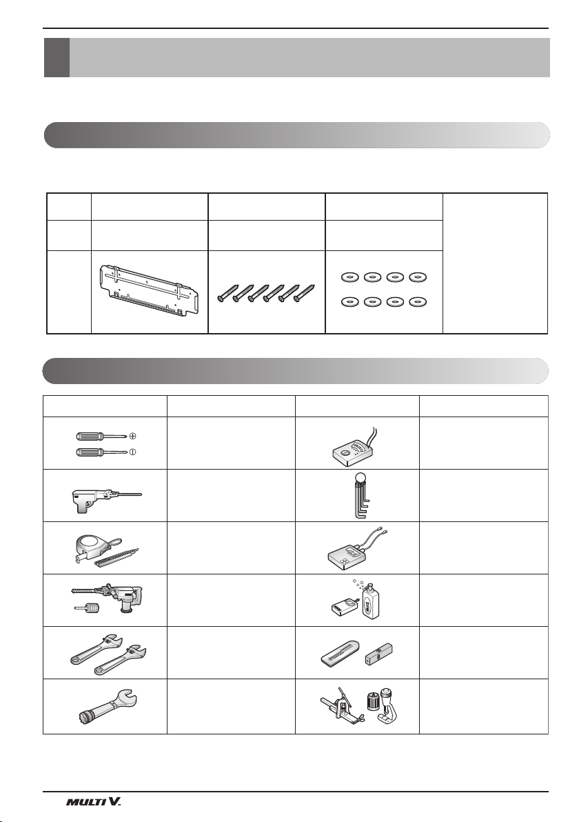
Installation Parts
Standard Accessories
Name
Quantity
Shape
Installation plate
Installation Tools
Figure FigureName
Measuring tape, Knife
Type "A" screw and
plastic anchor
Screw driver
Electric drill
Flat washer
6 EA1 EA
8 EA
Hexagonal wrench
(Other)
• Owner's manual
• Installation manual
• Drain Hose
• Wood screw for indoor
Name
Multi-meter
Ammeter
10 Indoor Unit
Hole core drill
Spanner
Torque wrench
Gas-leak detector
Thermometer,
Level
Flaring tool set
Page 11

Installation
Minimum floor area
(for R32)
ENGLISH
- The appliance shall be installed, operated and stored in a room with a floor area larger than the
minimum area.
- Use the graph of table to determine the minimum area.
Amin (m2)
- m : Total refrigerant amount in the system.
- Total refrigerant amount : factory refrigerant charge + additional refrigerant amount.
- Amin : minimum area for installation.
600
500
400
300
200
100
0
0 1.224 2 3 4 5 6 7 8
Floor standing
Wall mounted
Ceiling mounted
m (kg)
Floor location
m (kg) Amin (m
< 1.224
1.224
1.4 16.82
1.6 21.97
1.8 27.80
2.2 41.53
2.4 49.42
2.6 58.00
2.8 67.27
3.2 87.86
3.4 99.19
3.6 111.20
3.8 123.90
4.2 151.36
4.4 166.12
-
12.9
2 34.32
3 77.22
4 137.29
Floor location
2
m (kg) Amin (m
)
4.6 181.56
4.8 197.70
5 214.51
5.2 232.02
5.4 250.21
5.6 269.09
5.8 288.65
6 308.90
6.2 329.84
6.4 351.46
6.6 373.77
6.8 396.76
7 420.45
7.2 444.81
7.4 469.87
7.6 495.61
7.8 522.04
2
)
Wall mounted
m (kg) Amin (m
< 1.224
1.224
1.4 1.87
1.6 2.44
1.8 3.09
2.2 4.61
2.4 5.49
2.6 6.44
2.8 7.47
3.2 9.76
3.4 11.02
3.6 12.36
3.8 13.77
4.2 16.82
4.4 18.46
-
1.43
2 3.81
3 8.58
4 15.25
Wall mounted
2
m (kg) Amin (m
)
4.6 20.17
4.8 21.97
5 23.83
5.2 25.78
5.4 27.80
5.6 29.90
5.8 32.07
6 34.32
6.2 36.65
6.4 39.05
6.6 41.53
6.8 44.08
7 46.72
7.2 49.42
7.4 52.21
7.6 55.07
7.8 58.00
2
)
Ceiling Mounted
m (kg) Amin (m
< 1.224
1.224
1.4 1.25
1.6 1.63
1.8 2.07
2 2.55
2.2 3.09
2.4 3.68
2.6 4.31
2.8 5.00
3 5.74
3.2 6.54
3.4 7.38
3.6 8.27
3.8 9.22
4 10.21
4.2 11.26
4.4 12.36
2
-
0.956
Installation Manual 11
Ceiling Mounted
m (kg) Amin (m
)
4.6 13.50
4.8 14.70
5 15.96
5.2 17.26
5.4 18.61
5.6 20.01
5.8 21.47
6 22.98
6.2 24.53
6.4 26.14
6.6 27.80
6.8 29.51
7 31.27
7.2 33.09
7.4 34.95
7.6 36.86
7.8 38.83
2
)
Page 12

Installation
Wired remote controller installation
• Since the room temperature sensor is in the remote controller, the remote controller box should be installed in a place
away from direct sunlight, high humidity and direct supply of cold air to maintain proper space temperature.
Install the remote controller about 5 ft (1.5 m) above the floor in an area with good air circulation at an average
temperature.
Do not install the remote controller where it can be affected by:
- Drafts, or dead spots behind doors and in corners.
- Hot or cold air from ducts.
- Radiant heat from sun or appliances.
- Concealed pipes and chimneys.
- Uncontrolled areas such as an outside wall behind the remote controller.
- This remote controller is equipped with a seven segment LED. display. For proper display of the remote controller LED's,
the remote controller should be installed properly as shown in Fig.1.
(The standard height is 1.2~1.5 m from floor level.)
Remote Controller
no
TEMP
Remote Controller
no
TEMP
yes
TEMP
Remote Controller
5 feet
(1.5 m)
Fig.1 Typical locations for remote controller
nonono
12 Indoor Unit
Page 13

Installation
Installation parts you should purchase.
NOTICE
(Left and right
are identical)
(Left and right
are identical)
Sleeve
Bushing-Sleeve
Putty(Gum Type Sealer)
Bend the pipe as closely
on the wall as possible,
but be careful that it
doesn't break.
Vinyl tape (Wide)
• To carry out the drainage
test, remove the air filters
and pour water into the heat
exchanger.
• Apply after carrying out a
drainage test.
Saddle
There should be no space
between ceiling and the unit.
More than
200 mm
More than
200 mm
More than 50 mm
More than 50mm
Ceiling Mounting
Wall Mounting
Installation Map
ENGLISH
!
CAUTION
The Power cord connected to the unit should be selected according to the following
specifications.
Installation Manual 13
Page 14

Installation
NOTICE
Select the best Location
Indoor unit
1. Do not have any heat or steam near the unit.
2. Select a place where there are no obstacles
in front of the unit.
3. Make sure that condensation drainage can be
conveniently routed away.
4. Do not install near a doorway.
5. Ensure that the interval between a wall and
the left (or right) of the unit is more than
200 mm. The unit should be installed as low
as possible on the wall, allowing a minimum
of 50 mm from floor.
6. Use a stud finder to locate studs to prevent
unnecessary damage to the wall.
Preparing Work for Installation
Open panel front
1. Remove the five screws.
2. Release the claws in the 3 places indicated.
3. Pull up the Front Panel.
Cover pipe and cover side remove
1. Pull up the side cover of desired connecting
direction, then cover side is separated.
2. Pick the pipe hole of the side cover.
More than 200 mm
More than 200 mm
More than 50 mm
1
More than 200 mm
More than 50 mm
More than 200 mm
Claw
2
3
!
CAUTION
After removing the pipe hole, cut
the burr for safety.
When making pipe path through rear wall,
you don’t need to pick the pipe hole.
Drain hose junction
1. Remove the rubber stopple in the left side
drain hole. (Do not use the right side drain
hole)
2. Insert drain hose into the handle of drain pan,
and join drain hose and connecting hose
according to the figure by.
14 Indoor Unit
Page 15

Installation
Suspension bolt
piping hole
(Ø 45)
Mounting the installation plate(Wall Mounting)
The wall you select should be strong and solid
enough to prevent vibration
1. Mount the installation plate on the wall with
type "A" screws. If mounting the unit on a
concrete wall, use anchor bolts.
• Mount the installation plate horizontally by
aligning the centerline using a level.
2. Measure the wall and mark the centerline. It
is also important to use caution concerning
the location of the installation plate-routing
of the wiring to power outlets is through the
walls typically. Drilling the hole through the
wall for piping connections must be done
safely.
Type "A" screw
70
Ø 65 mm
Left rear piping
Installation Plate
Installation plate
120
more than 200
Floor
Mounting the anchor Nut & Bolt(Ceiling Mounting)
• Prepare 4 suspension bolts. (Each bolts length
should be same.)
• Measure and mark the position for the Suspension
bolts and the piping hole.
• Drill the hole for anchor nut on the ceiling.
• Insert the nuts and washer onto the suspension
bolts for locking the suspension bolts on the ceiling.
• Mount the suspension bolts to the anchor-nuts
firmly.
• Secure the hangers onto the Suspension bolts
(adjust level roughly.) using nuts, washers.
• Adjust a level with a level gauge on the direction of
left-right, back-forth by adjusting suspension bolts.
• Adjust a level on the direction of top-bottom by
adjusting supension bolts. Then the unit will be
declined to the bottomside so as to drain well.
!
CAUTION
Tighten the nut and bolt to prevent unit falling.
!
CAUTION
• When mechanical connectors are reused
indoors, sealing parts shall be renewed.
(for R32)
• When flared joints are reused indoors, the
flare part shall be re-fabricated. (for R32)
Anchor nut
Ceiling
Nut
Suspension
bolts
piping hole
piping hole
(Ø 45)
(Ø 45)
Hanging bolt
(W3/8 or M10)
Nut
(W3/8 or M10)
Washer
40
820
Suspension bolt
Suspension bolt
Hangen
Ø 65 mm
Right rear piping
Suspension
bolts
Max.
12 mm
Washer
Flat washer for M10
(accessory)
Flat washer for M10
(accessory)
Nut
(W3/8 or M10)
70
235
Nut
Unit : mm
50
100
Reference
of piping
hole (Ø 45)
Unit : mm
ENGLISH
Installation Manual 15
Page 16

Installation
!
CAUTION
Installation Information For right piping. Follow the instruction below.
Good case
For left piping. Follow the instruction below.
1. Press on the upper side of clamp. (Ⓐ)
2. Unfold the tubing to downward slowly. (Ⓑ)
3. Bend the tubing to the left side of chassis.
Bad case
1. Following bending type from right to
left could cause problem of pipe damage.
16 Indoor Unit
Page 17

Installation
Downward slope
Do not raise
Accumulated
drain water
Tip of drain hose
dipped in water
Air
Waving
Water
leakage
Water
leakage
Ditch
Less than
50 mm gap
Water
leakage
Checking the Drainage
1. Set the air direction louvers up-and-down to
the position(horizontally) by hand.
To check the drainage.
1. Pour a glass of water on the evaporator.
2. Ensure the water flows through the drain hose
of the indoor unit without any leakage and
goes out the drain exit.
n Checking the Drainage
1. Remove the Air Filter.
• To remove air filter, take hold of tab and pull
slightly upwards.
2. Check the drainage.
• Spray one or two glasses of water upon the
evaporator.
• Ensure that water flows drain hose of indoor
unit without any leakage.
Drain piping
1. The drain hose should point downward for
easy drain flow.
2. Do not make drain piping like the following.
ENGLISH
Panel Front Assembly
1. Suspend the hook of panel front in
the groove.
2. Press the panel front.
3. Screw up panel front.
1
2
3
Installation Manual 17
Page 18

Installation
Flaring Work
Main cause for gas leakage is due to defect in flaring work. Carry out correct flaring work in the
following procedure.
Cutting the pipes and the cable.
1. Use the piping kit accessory or the pipes
purchased locally.
2. Measure the distance between the indoor
and the outdoor unit.
3. Cut the pipes a little longer than measured
distance.
4. Cut the cable 1.5 m longer than the pipe
length.
Removing burrs
1. Completely remove all burrs from the cut
cross section of pipe/tube.
2. Put the end of the copper tube/pipe in a
downward direction as you remove burrs in
order to avoid dropping burrs into the tubing.
Copper
pipe
90°
Point down
Slanted Uneven Rough
Pipe
Reamer
Putting nut on
• Remove flare nuts attached to indoor and
outdoor unit, then put them on pipe/tube
having completed burr removal.
(not possible to put them on after flaring work)
Flaring work
1. Firmly hold copper pipe in a die in the
dimension shown in the table below.
2. Carry out flaring work with the flaring tool.
Pipe diameter
inch (mm)
A inch (mm)
Wing nut type Clutch type
Ø 1/4 (Ø 6.35) 0.04~0.05 (1.1~1.3)
Ø 3/8 (Ø 9.52) 0.06~0.07 (1.5~1.7)
Ø 1/2 (Ø 12.7) 0.06~0.07 (1.6~1.8)
Ø 5/8 (Ø 15.88) 0.06~0.07 (1.6~1.8)
0~0.02
(0~0.5)
Ø 3/4 (Ø19.05) 0.07~0.08 (1.9~2.1)
Check
1. Compare the flared work with the figure by.
2. If a flared section is defective, cut it off and
do flaring work again.
Flare nut
Copper tube
<Wing nut type>
Smooth all round
Even length
all round
Bar
Copper pipe
<Clutch type>
Inside is shiny without scratches
= Improper flaring =
Inclined
Surface
Cracked Uneven
damaged
"A"
thickness
18 Indoor Unit
Page 19

Installation
Connecting pipe
Connecting
cable
Tape
Drain hose
Drill a Hole in the Wall
• Drill the piping hole with a Ø 65 mm hole core
drill. Drill the piping hole at either the right or
the left with the hole slightly slanted to the
outdoor side.
Indoor
WALL
Outdoor
5-7 mm
Connecting the Piping
Indoor
Preparing the indoor unit's piping and drain hose for installation through the wall.
1. Route the indoor tubing and the drain hose in
the direction of rear left or right
ENGLISH
(3/16"~5/16")
2. Tape the tubing, drain hose and the
connecting cable. Be sure that the drain hose
is located at the lowest side of the bundle.
Locating at the upper side can cause drain
pan to overflow inside the unit.
!
CAUTION
If the drain hose is routed inside the room, insulate the hose with an
insulation material* so that dripping from "sweating"(condensation) will
not damage furniture or floors.
*Foamed polyethylene or equivalent is recommended.
Installation Manual 19
Page 20

Installation
Connecting the piping with the indoor
unit and drain hose with drain pipe
1. Align the center of the pipings and sufficiently
tighten the flare nut by hand.
2. Tighten the flare nut with a wrench.
Indoor unit tubing Flare nut Pipings
Outside diameter Torque
mm inch kgf.m
Ø 6.35 1/4 1.8~2.5
Ø 9.52 3/8 3.4~4.2
Ø 12.7 1/2 5.5~6.6
Ø 15.88 5/8 6.3~8.2
Ø 19.05 3/4 9.9~12.1
3. When extending the drain hose at the indoor
unit, install the drain pipe.
Wrap the insulation material around
the connecting portion.
1. Overlap the connection pipe insulation
material and the indoor unit pipe insulation
material. Bind them together with vinyl tape
so that there may be no gap.
2. Wrap the area which accommodates the rear
piping housing section with vinyl tape.
Torque wrench
Indoor unit tubing
Drain pipe
Adhesive
Connection
pipe
Vinyl tape
(wide)
Connecting cable
Vinyl tape(narrow)
Plastic bands
Wrap with vinyl tape
Spanner (fixed)
Flare nut
Connection pipe
Indoor unit drain hose
Insulation material
Indoor
unit pipe
3. Bundle the piping and drain hose together by
wrapping them with vinyl tape over the range
within which they fit into the rear piping
housing section.
20 Indoor Unit
Pipe
Drain hose
Pipe
Vinyl tape(narrow)
Wrap with vinyl tape
Vinyl tape(wide)
Page 21

Installation
Terminal block of indoor unit
Terminal block of outdoor unit
1(L) 2(N) 3 4
Indoor power input
IDU IDU
Outdoor unit
Indoor unit
Central controller
SODU SODU
DRY1
DRY2
GND
INTERNET
12 V
Round pressure terminal
Power cable
Precautions when laying power wiring
Use round pressure terminals for connections to the power terminal block.
When none are available, follow the instructions below.
• Do not connect wiring of different thicknesses to the power terminal block. (Slack in the power
wiring may cause abnormal heat.)
• When connecting wiring which is the same thickness, do as shown in the figure below.
!
CAUTION
Make sure that the screws of the terminal are free from looseness.
ENGLISH
Wiring Connection
• Connect the cable to the indoor unit by connecting the wires to the terminals on the control
board individually according to the outdoor unit connection. (Ensure that the color of the wires of
the outdoor unit and the terminal No. are the same as those of the indoor unit.)
The earth wire should be longer than the common wires.
• When installing, refer to the circuit diagram on the Control Box of Indoor Unit.
• When installing, refer to the wiring diagram on the Control Cover Inside Outdoor Unit.
Installation Manual 21
Page 22

Installation
Air
Conditioner
Main power source
Connection Terminal
2
1.5 mm
L
N
G
1.5 mm
1.5 mm
2
• The capacity of connection terminal should be over 250 V 20 A. And when
2
connecting the power line and communication line between indoor units,
you are advised to use the connection terminal.
• When you are not able to use the connection terminal, fix each power
line/communication line by using the clamp cord attached in the product,
together with the clamp cord and screw in the accessories.
Please consider the all
connected capacity of
indoor units.
!
CAUTION
• The above circuit diagram is subject to change without notice.
• Be sure to connect wires according to the wiring diagram.
• Connect the wires firmly, so that not to be pulled out easily.
• Connect the wires according to color codes by referring the wiring diagram.
!
CAUTION
If a power plug is not to be used, provide a
circuit breaker between power source and
the unit as shown below.
Circuit Breaker
Use a circuit
breaker or time
delay fuse.
!
CAUTION
After the confirmation of the above conditions,
prepare the wiring as follows:
1) Never fail to have an individual power circuit specifically for the air conditioner. As for the method
of wiring, be guided by the circuit diagram posted on the inside of control cover.
2) The screws which fasten the wiring in the casing of electrical fittings are liable to come loose
from vibrations to which the unit is subjected during the course of transportation. Check them
and make sure that they are all tightly fastened. (If they are loose, it could cause burn-out of the
wires.)
3) Specification of power source.
4) Confirm that electrical capacity is sufficient.
5) See to that the starting voltage is maintained at more than 90 percent of the rated voltage marked
on the name plate.
6) Confirm that the cable thickness is as specified in the power source specification.
(Particularly note the relation between cable length and thickness.)
7) Always install an earth leakage circuit breaker where it is wet or moist.
8) The following would be caused by voltage drop.
• Vibration of a magnetic switch, which will damage the contact point, fuse breaking, disturbance of the
normal function of the overload protection device.
9) The means for disconnection from a power
supply shall be incorporated in the fixed wiring and have an air gap contact separation of at least
3mm in each active(phase) conductors.
22 Indoor Unit
Page 23

Installation
DIP Switch Setting
BLDC
SW1
SW2
SW3
SW4
SW5
SW6
SW7
SW8
For Multi V Models, DIP switch 1, 2, 6, 8 must be set OFF.
Function
Communication
Cycle
Group Control
Dry Contact Mode
Install
Heater linkage
Ventilator linkage
-
!
CAUTION
Description
Selection of Communication or Non-communication
Selection of C/O or H/P
Selection of Master or Slave
Selection of Dry Contact Mode
Selection of Ceiling or Floor
Selection of Heater linkage
Selection of Ventilator linkage
-
Setting Off
Communication
Heat Pump
Master
Variable
Ceiling
Linkage Removal
Linkage Removal
Non-communication
-
Setting On
Cooling Only
Slave
Auto
Floor
Working
Working
-
ENGLISH
Default
Off
Off
Off
Off
Off
Off
Off
Off
Installation Manual 23
Page 24

Installation
Group Control Setting
1. Group Control 1
n Wired remote controller 1 + Indoor units
LGAP Network System
Master
Master
Slave
Display Error Message
Slave
Only connect serial signal and GND lines
between slave indoor unit
Slave
GND
Signal
12 V
n DIP Switch in PCB (Cassette and Duct Type indoor units)
Master Setting Slave Setting
- No. 3 Off - No. 3 On
1. It is possible to 16 indoor units(Max) by one wired remote controller.
Set only one indoor unit to Master, set the others to Slave.
2. It is possible to connect with every type of indoor units.
3. It is possible to use wireless remote controller at the same time.
4. It is possible to connect with Dry Contact and Central controller at the same time.
- The Master indoor unit is possible to recognize Dry Contact and Central Controller only.
- In case of Central controller and Group controller at the same time, it is possible to connect standard 2
series indoor units or later since Feb. 2009.
- In case of Central controller setting, the Central controller can control indoor units after setting only the
address of master indoor unit.
- Slave indoor unit will be operated like master indoor unit.
- Slave indoor unit can not be individually controlled by Central controller.
- Some remote controller can’t perform with Dry Contact and Central controller at the same time.
So contact us further information about it.
24 Indoor Unit
Page 25

Installation
5. In case of any error occurs at indoor unit, display on the wired remote controller.
Exception of the error indoor unit, an individual indoor unit control possibility.
6. In case of Group Control, it is possible to use following functions.
- Selection of operation options (operation/stop/mode/set temperature)
- Control of flow rate (High/Middle/Low)
- It is not possible at some functions.
h Master/Slave setting of indoor units be set possible using a PCB DIP Switch.
h It is possible to connect indoor units since Feb. 2009. In the other cases, please contact LGE.
h It can be the cause of malfuctions when there is no setting of master and slave.
2. Group Control 2
LGAP Network System
Master
Donʼt connect serial 12 V line
Master
Slave
Slave
GND
Signal
12 V
ENGLISH
Display Error Message
Master
Master
h It is possible to control N indoor units by wired remote controller M units. (M+N ≤ 17 Units)
Other than those, it is same with the Group Control 1.
Installation Manual 25
Page 26

Installation
3. Group Control 3
n Mixture connection with indoor units and Fresh Air Intake Unit
LGAP Network System
FAU
Master
Master
FAU
Slave
Display Error Message
Master
Master
Slave
GND
Signal
12 V
h In case of connecting with standard indoor unit and Fresh Intake Unit, separate Fresh Air
Intake Unit with standard units. (Because setting temperature are different.)
h Other than those, it is same with Group Control 1.
FAU
Standard Standard
FAU
Standard Standard
FAUFAU
* FAU : Fresh Air Intake Unit
Standard: Standard Indoor Unit
26 Indoor Unit
Page 27

Installation
4. 2 Remote Control
n Wired remote controller 2 + Indoor unit 1
LGAP Network System
Master
Display Error
Message
Master
1. It is possible to connect two wired remote controllers with one indoor unit.
2. Every types of indoor unit is possible to connect two remote controller.
3. It is possible to use wireless remote controller at the same time.
4. It is possible to connect with Dry Contact and Central controller at the same time.
5. In case of any error occurs at indoor unit, display on the wired remote controller.
6. There isnʼt limits of indoor unit function.
h Maximum 2 wired remote controllers can be connected with 1 indoor unit.
Slave
ENGLISH
Installation Manual 27
Page 28

Installation
Slave
Master
Master
PZCWRCG3
Master Slave
PZCWRC2
5. Accessories for group control setting
It is possible to set group control by using below accessories.
Indoor unit 2 EA + Wired remote controller Indoor unit 1 EA + Wired remote controller 2 EA
h PZCWRCG3 cable used for connection h PZCWRC2 cable used for connection
28 Indoor Unit
Page 29

Installation
Model Designation
ARN U G12 AVE 4
Airborne Noise Emission
Serial Number
Combinations of functions
A : Basic function L : Neo Plasma(Wall Mounted)
C : Plasma(Ceiling Cassette)
G : Low Static K : High Sensible Heat
U : Floor Standing without Case
SE/S8 - R : Mirror V : Silver B : Blue(ART COOL Type Panel Clolr)
SF - E : Red V : Silver G : Gold 1 : Kiss (Photo changeable)
Q : Console Z : Fresh Air Intake Unit
Chassis Name
Electrical Ratings
1 : 1Ø, 115 V, 60 Hz
6 : 1Ø, 220 - 240 V, 50 Hz
3 : 1Ø, 208/230 V, 60 Hz
Total Cooling Capacity in Btu/h
EX) 5 000 Btu/h ➝ '05' 18 000 Btu/h ➝ '18'
Combination of Inverter Type and Cooling Only or Heat Pump
N : AC Inverter and H/P V : AC Inverter and C/O
U : DC Inverter and H/P and C/O
System with Indoor Unit using R32/R410A
2 : 1Ø, 220 V, 60 Hz
7 : 1Ø, 100 V, 50/60 Hz
G :
1Ø, 220 - 240 V, 50 Hz/1Ø, 220 V, 60 Hz
ENGLISH
The A-weighted sound pressure emitted by this product is below 70 dB.
** The noise level can vary depending on the site.
The figures quoted are emission level and are not necessarily safe working levels. Whilst there is a
correlation between the emission and exposure levels, this cannot be used reliably to determine
whether or not further precautions are required. Factor that influence the actual level of exposure of
the workforce include the characteristics of the work room and the other sources of noise, i.e. the
number of equipment and other adjacent processes and the length of time for which an operator
exposed to the noise. Also, the permissible exposure level can vary from country to country. This
information, however, will enable the user of the equipment to make a better evaluation of the hazard
and risk.
Limiting concentration
Limiting concentration is the limit of Freon gas concentration where immediate measures can be
taken without hurting human body when refrigerant leaks in the air. The limiting concentration shall
be described in the unit of kg/m
n Calculate refrigerant concentration
Refrigerant concentration =
3
(Freon gas weight per unit air volume) for facilitating calculation
Limiting concentration : 0.44 kg/m3(R410A)
Total amount of replenished refrigerant in refrigerant facility (kg)
Capacity of smallest room where indoor unit is installed (m
3
)
Installation Manual 29
Page 30

30 Indoor Unit
Page 31

 Loading...