

LG ARNU09GSJR4 INSTALLATION MANUAL

P/NO : MFL70407001
INSTALLATION MANUAL
AIR
CONDITIONER
www.lg.com
Please read this installation manual completely before installing the product.
Installation work must be performed in accordance with the national wiring
standards by authorized personnel only.
Please retain this installation manual for future reference after reading it thoroughly.
WALL MOUNTED
Original instruction
Copyright © 2017 LG Electronics Inc. All Rights Reserved.
ENGLISH ESPAÑOL

TIPS FOR SAVING ENERGY
2
ENGLISH
TIPS FOR SAVING ENERGY
Here are some tips that will help you minimize the power consumption when you use the air
conditioner. You can use your air conditioner more efficiently by referring to the instructions
below:
• Do not cool excessively indoors. This may be harmful for your health and may consume more
electricity.
• Block sunlight with blinds or curtains while you are operating the air conditioner.
• Keep doors or windows closed tightly while you are operating the air conditioner.
• Adjust the direction of the air flow vertically or horizontally to circulate indoor air.
• Speed up the fan to cool or warm indoor air quickly, in a short period of time.
• Open windows regularly for ventilation as the indoor air quality may deteriorate if the air conditioner is used for many hours.
• Clean the air filter once every 2 weeks. Dust and impurities collected in the air filter may block the
air flow or weaken the cooling / dehumidifying functions.
For your records
Staple your receipt to this page in case you need it to prove the date of purchase or for warranty
purposes. Write the model number and the serial number here:
Model number :
Serial number :
You can find them on a label on the side of each unit.
Dealer’s name :
Date of purchase :

IMPORTANT SAFETY INSTRUCTIONS
IMPORTANT SAFETY INSTRUCTIONS
READ ALL INSTRUCTIONS BEFORE USING THE APPLIANCE.
Always comply with the following precautions to avoid dangerous situations and ensure peak
performance of your product
WARNING
!
It can result in serious injury or death when the directions are ignored
CAUTION
!
It can result in minor injury or product damage when the directions are ignored
WARNING
!
• Installation or repairs made by unqualified persons can result in hazards to you and others.
• Installation MUST conform with local building codes.
• The information contained in the manual is intended for use by a qualified service technician
familiar with safety procedures and equipped with the proper tools and test instruments.
• Failure to carefully read and follow all instructions in this manual can result in equipment malfunction, property damage, personal injury and/or death.
Installation
• Don’t use a power cord, a plug or a loose socket which is damaged.
- Otherwise, it may cause a fire or electrical shock.
• For electrical work, contact the dealer, seller, a qualified electrician, or an Authorized Service Center.
- Do not disassemble or repair the product. There is risk of fire or electric shock.
• Always ground the product.
- There is risk of fire or electric shock.
• Install the panel and the cover of control box securely.
- There is risk of fire or electric shock.
• Always install a dedicated circuit and breaker.
- Improper wiring or installation may cause fire or electric shock.
• Use the correctly rated breaker or fuse.
- There is risk of fire or electric shock.
• Do not modify or extend the power cable.
- There is risk of fire or electric shock.
• Do not let the air conditioner run for a long time when the humidity is very high and a door or a window is left open.
- Moisture may condense and wet or damage furniture.
• Be cautious when unpacking and installing the product.
- Sharp edges could cause injury. Be especially careful of the case edges and the fins on the con-
denser and evaporator.
• For installation, always contact the dealer or an Authorized Service Center.
- There is risk of fire, electric shock, explosion, or injury.
3
ENGLISH

4
ENGLISH
Operation
Installation
IMPORTANT SAFETY INSTRUCTIONS
• Do not install the product on a defective installation stand.
- It may cause injury, accident, or damage to the product.
• Be sure the installation area does not deteriorate with age.
- If the base collapses, the air conditioner could fall with it, causing property damage, product failure,
and personal injury.
• There is a risk of fire and explosion.
- Inert gas (nitrogen) should be used when you check plumbing leaks, cleaning or repairs of pipes
etc.
If you are using combustible gases including oxygen, product may have the risk of fires and explosions.
• Use a vacuum pump or Inert (nitrogen) gas when doing leakage test or air purge. Do not compress
air or Oxygen and do not use Flammable gases. Otherwise, it may cause fire or explosion.
- There is the risk of death, injury, fire or explosion.
• Do not turn on the breaker or power under condition that front panel, cabinet, top cover, control box
cover are removed or opened.
- Otherwise, it may cause fire, electric shock, explosion or death.
• Do not store or use flammable gas or combustibles near the product.
- There is risk of fire or failure of product.
CAUTION
!
• Always check for gas (refrigerant) leakage after installation or repair of product.
- Low refrigerant levels may cause failure of product.
• Install the drain hose to ensure that water is drained away properly.
- A bad connection may cause water leakage.
• Keep level even when installing the product.
- To avoid vibration or water leakage.
• Use two or more people to lift and transport the product.
- Avoid personal injury.

TABLE OF CONTENTS
TABLE OF CONTENTS
5
ENGLISH
2 TIPS FOR SAVING EN-
ERGY
3 IMPORTANT SAFETY IN-
STRUCTIONS
6 INSTALLATION PARTS
6 INSTALLATION TOOLS
7 INSTALLATION MAP
8 INSTALLATION
8 Select the best Location
8 Fixing Installation Plate (SJ/SK)
9 Drill a Hole in the Wall
9 Flaring Work
10 Connecting the Piping
14 Checking the Drainage
16 Manual the decor, air filter Assembly &
Disassembly
17 Wiring Connection
19 DIP Switch Setting
20 Group Control Setting
25 Model Designation
25 Airborne Noise Emission
25 Limiting concentration
INSTALLATION PARTS
6
ENGLISH
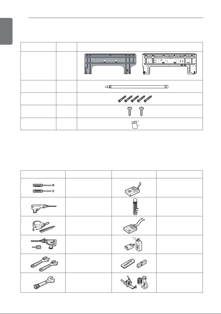
INSTALLATION PARTS
Name
Installation plate
Quantity Shape
1 EA
SJ SK
Drain hose
Type "A" screw
Type "C" screw
Cloth tape
Cloth tape is not attached to the product.
1 EA
5 EA
2 EA
1 EA
INSTALLATION TOOLS
Figure FigureName
Screw driver
Name
Multi-meter
Electric drill
Measuring tape, Knife
Hole core drill
Spanner
Torque wrench
Hexagonal wrench
Ammeter
Gas-leak detector
Thermometer,
Level
Flaring tool set
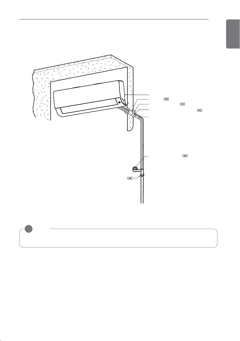
INSTALLATION MAP
Vinyl tape (Wide)
• Apply after carrying out a
drainage test.
• To carry out the drainage
test, remove the air filters
and pour water into the heat
exchanger.
Saddle
Installation plate
Sleeve
Bushing-Sleeve
Putty(Gum Type Sealant)
Bend the pipe as closely
on the wall as possible,
but be careful that it
doesn't break.
INSTALLATION MAP
7
ENGLISH
* The feature can be changed according to type of model.
NOTE
!
• You should purchase the installation parts.
8
ENGLISH
INSTALLATION
INSTALLATION
Select the best Location
- There should not be any heat or steam near
the unit.
- Select a place where there are no obstacles
around of the unit.
- Make sure that condensation drainage can
be conveniently routed away.
- Do not install near a doorway.
- Ensure that the interval between a wall and
the left (or right) of the unit is more than 100
mm. The unit should be installed as high as
possible on the wall, allowing a minimum of
200 mm from ceiling.
- Use a metal detector to locate studs to prevent unnecessary damage to the wall.
More than
100
More than 2300
* The feature can be changed according to
type of model.
CAUTION
!
Install the indoor unit on the wall where
the height from the floor is more than
2300 mm.
More than 200
More than
100
(Unit : mm)
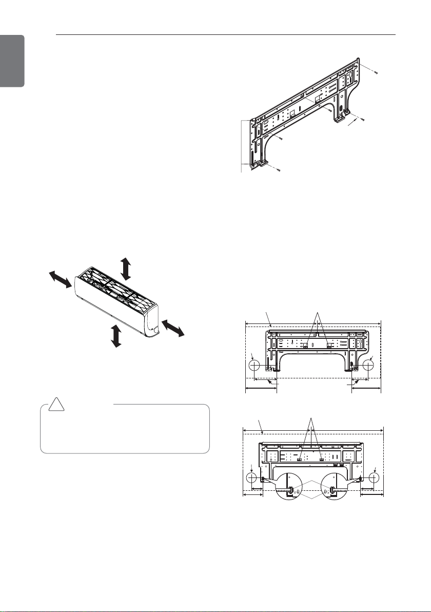
Installation Plate
Type "A" Screws
Chassis
Hook
2 Measure the wall and mark the centerline.
It is also important to use caution concerning the location of the installation plate.
Routing of the wiring to power outlets is
through the walls typically. Drilling the hole
through the wall for piping connections
must be done safely.
Unit Outline
Ø65
Left rear piping
Unit Outline
Place a level on raised tab
418 418
Installation Plate
98 134
152
Place a level on raised tab
494 504
Ø65
194
(Unit : mm)
Right rear piping
Fixing Installation Plate
The wall you select should be strong and solid
enough to prevent vibration
1 Mount the installation plate on the wall
with type "A" screws. If mounting the unit
on a concrete wall, use anchor bolts.
- Mount the installation plate horizontally
by aligning the centerline using Horizontal
meter .
Ø65
Measuring
83
Tubatura posteriore sinistra
134
Tape
Measuring Tape
Hanger
Ø65
83
150
(Unit : mm)
Right rear piping
INSTALLATION
Pipe
Reamer
Point down
9
ENGLISH
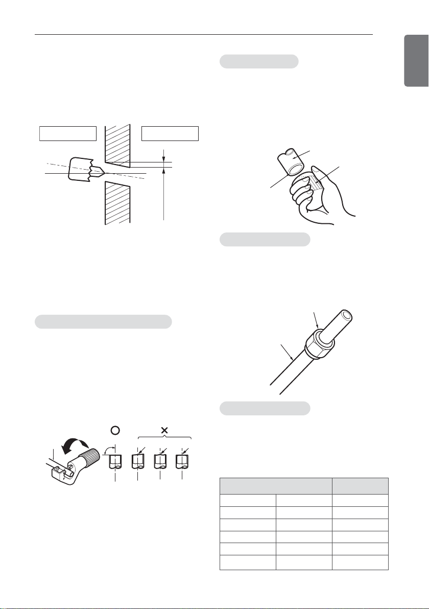
Drill a Hole in the Wall
- Drill the piping hole with a ø65 mm hole core
drill. Drill the piping hole at either the right or
the left with the hole slightly slanted to the
outdoor side.
WALL
Indoor
Outdoor
5-7mm
(3/16"~5/16")
Flaring Work
Main cause for gas leakage is due to defect of
flaring work. Carry out correct flaring work in
the following procedure.
Cut the pipes and the cable
1 Use the piping kit accessory or the pipes
purchased locally.
2 Measure the distance between the indoor
and the outdoor unit.
3 Cut the pipes a little longer than measured
distance.
4 Cut the cable 1.5m longer than the pipe
length.
Copper
pipe
90°
Slanted Uneven Rough
Burrs removal
1. Completely remove all burrs from the cut
cross section of pipe/tube.
2. While removing burrs put the end of the
copper tube/pipe in a downward direction
while removing burrs location is also
changed in order to avoid dropping burrs
into the tubing.
Putting nut on
- Remove flare nuts attached to indoor and
outdoor unit, then put them on pipe/tube
having completed burr removal.
(not possible to put them on after finishing
flare work)
Flare nut
Copper tube
Flaring work
1 Firmly hold copper pipe in a bar with the di-
mension shown in below table table
below.
2 Carry out flaring work with the flaring tool.
Outside diameter
mm inch mm
Ø6.35 1/4 1.1~1.3
Ø9.52 3/8 1.5~1.7
Ø12.7 1/2 1.6~1.8
Ø15.88 5/8 1.6~1.8
Ø19.05 3/4 1.9~2.1
A
 Loading...