


LG Multi Type
Air Conditioner
(Ceiling Duct Type)
INSTALLATION MANUAL
LG
IMPORTANT
• Please read this installation manual completely before
installing the product.
• When the power cord is damaged, replacement work shall
be performed by authorized personnel only.
• Installation work must be performed in accordance with
the national wiring standards by authorized personnel
only.
• Please retain this installation manual for future reference after
reading it thoroughly.
website http://www.lgservice.com
e-mail http://lgservice.com/techsup.html

2 Multi Type Air Conditioner
Multi Type Air Conditioner Installation Manual
TABLE OF CONTENTS
Safety Precautions..............3
Introduction .........................6
Installation of Indoor...........7
Connecting Pipes to the
Indoor Unit.........................12
Connecting Pipes to the ..14
Checking the Drainage .....14
Connecting Cables
between Indoor Unit .........15
Group Control....................17
Two Thermistor system....17
E.S.P.(External Static
Pressure) Setting...............18
How to Set E.S.P? .............19
Installation
Requirements
Required Parts Required Tools
•
Four Type “A” screws
•
Connecting cable
•
Level
•
Screw driver
•
Electric drill
•
Hole core drill(ø70mm)
•
Pipes: Gas side ...........
1
/2",3/8"
Liquid side...........................
1
/4"
•
Insulated drain hose
•
Insulation materials
•
Flaring Tools set
•
Additional Drain hose
(Inner Dia...............25mm)
•
Screw driver
•
Hexagonal Wrench (4mm/5mm)
•
Gas-leak Detector
Safety Precautions
Installation Manual 3
To prevent injury to the user or other people and property damage, the following instructions must be
followed.
■ Be sure to read before installing the air conditioner.
■ Be sure to observe the cautions specified here as they include important items related to safety.
■ Incorrect operation due to ignoring instruction will cause harm or damage. The seriousness is
classified by the following indications.
■ Meanings of symbols used in this manual are as shown below.
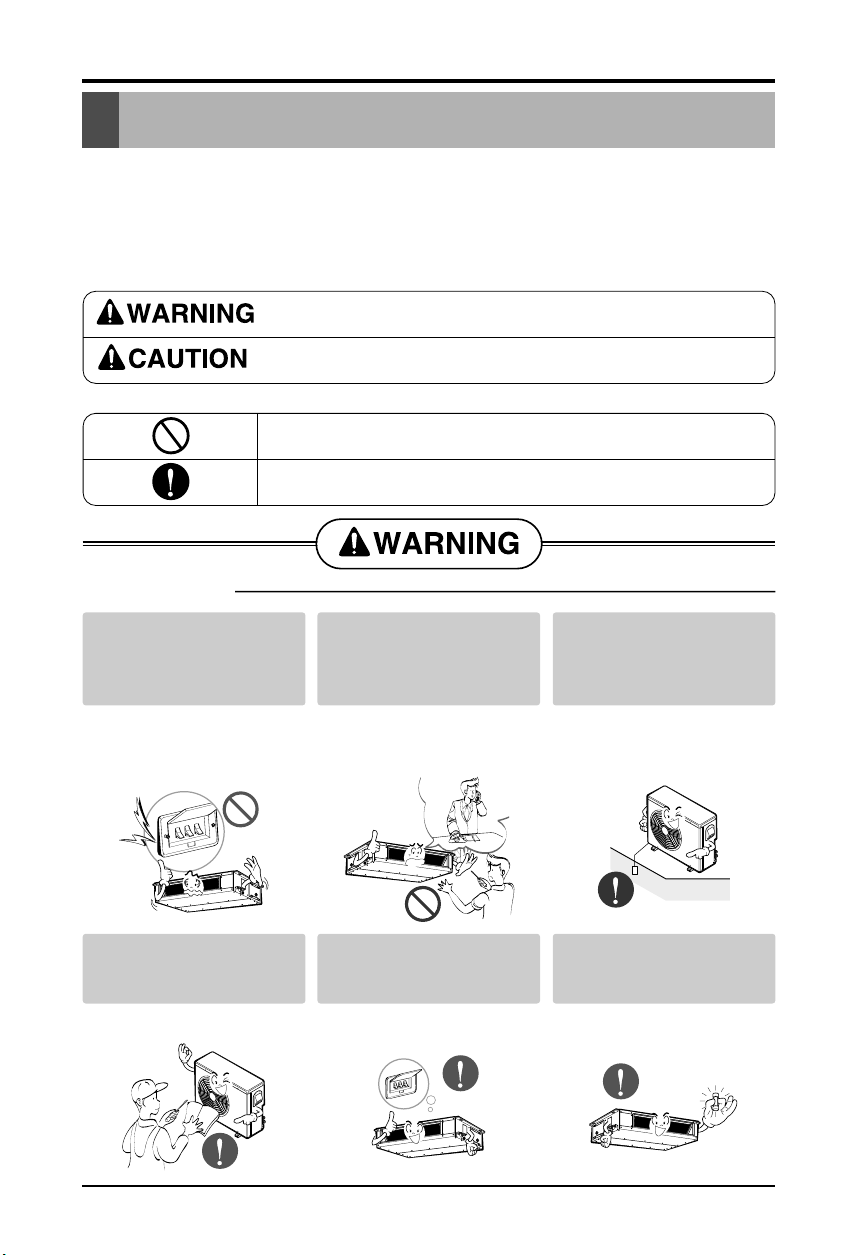
This symbol indicates the possibility of death or serious injury.
This symbol indicates the possibility of injury or damage to properties only.
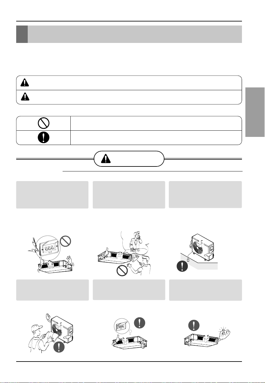
■ Installation
Be sure not to do.
Be sure to follow the instruction.
Safety Precautions
Do not use a defective or
underrated circuit breaker.
Use this appliance on a
dedicated circuit.
• There is risk of fire or electric
shock.
For electrical work, contact
the dealer, seller, a
qualified electrician, or an
Authorized Service Center.
• Do not disassemble or repair
the product. There is risk of
fire or electric shock.
Always ground the
product.
• There is risk of fire or electric
shock.
Install the panel and the
cover of control box
securely.
• There is risk of fire or electric
shock.
Always install a dedicated
circuit and breaker.
• Improper wiring or installation
may cause fire or electric
shock
Use the correctly rated
breaker or fuse.
• There is risk of fire or electric
shock.
Safety Precautions
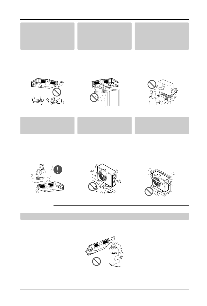
■ Operation
4 Multi Type Air Conditioner
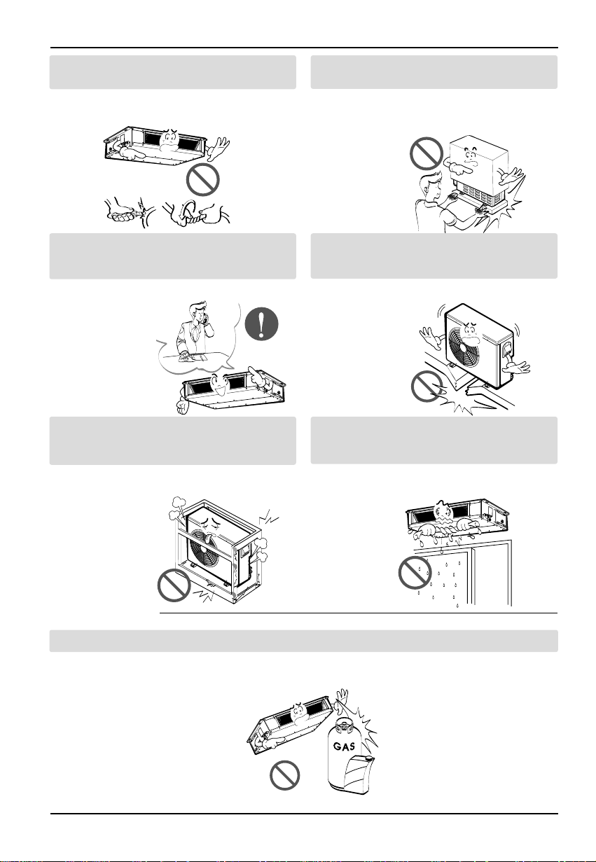
Do not modify or extend
the power cable.
• There is risk of fire or electric
shock.
Do not let the air
conditioner run for a long
time when the humidity is
very high and a door or a
window is left open.
• Moisture may condense and
wet or damage furniture.
Be cautious when
unpacking and installing
the product.
• Sharp edges could cause
injury.Be especially careful of
the case edges and the fins on
the condenser and evaporator.
For installation, always
contact the dealer or an
Authorized Service Center.
• There is risk of fire, electric
shock, explosion, or injury.
Do not install the product
on a defective installation
stand.
• It may cause injury, accident,
or damage to the product.
Be sure the installation
area does not deteriorate
with age.
• If the base collapses, the air
conditioner could fall with it,
causing property damage,
product failure, and personal
injury.
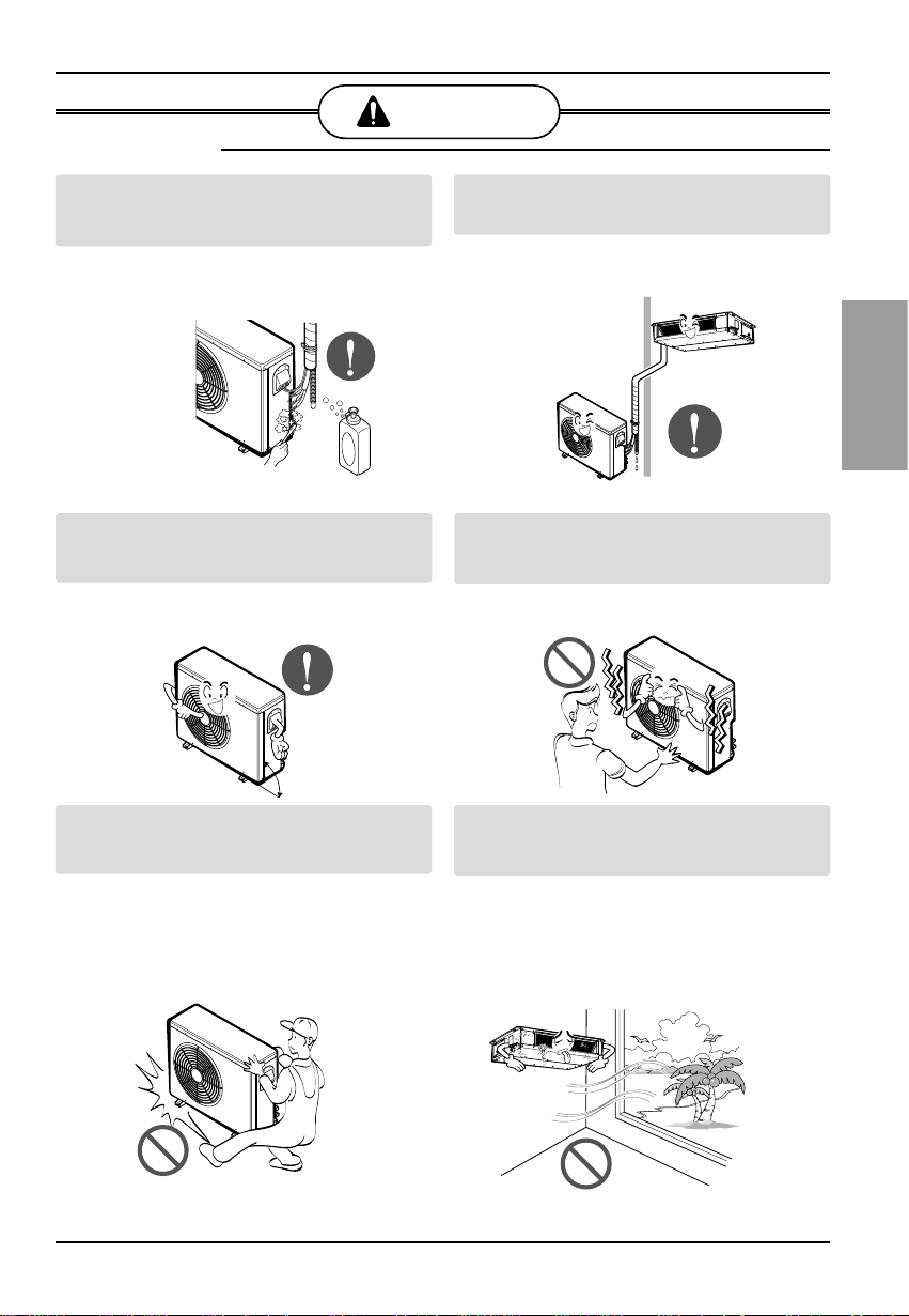
Do not store or use flammable gas or combustibles near the product.
• There is risk of fire or failure of product.
Gasolin
Installation Manual 5
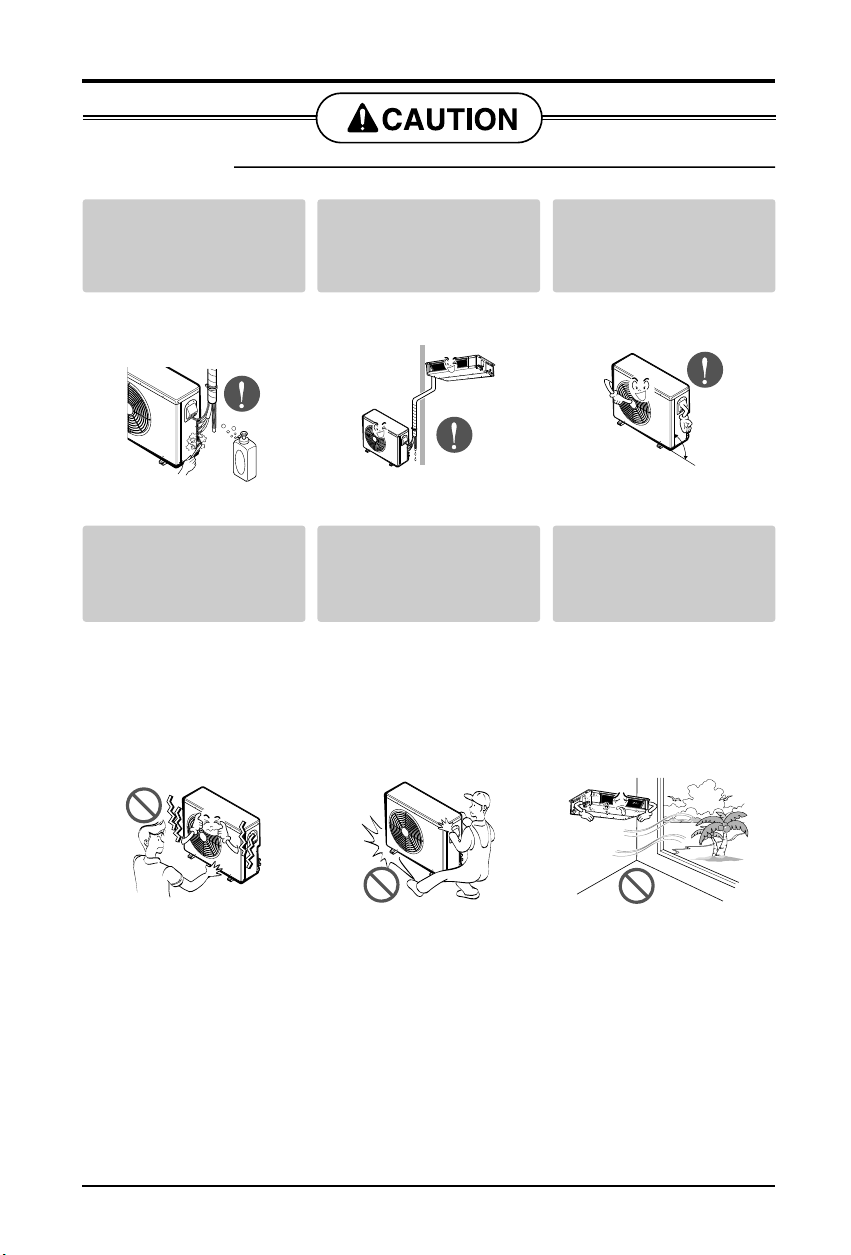
Safety Precautions
Always check for gas
(refrigerant) leakage after
installation or repair of
product.
• Low refrigerant levelsmay
cause failure of product.
Install the drain hose to
ensure that water is
drained away properly.
• A bad connection may cause
water leakage.
Keep level even when
installing the product.
• To avoid vibration or water
leakage.
Do not install the product
where the noise or hot air
from the outdoor unit could
damage the neighborhoods.
• It may cause a problem for
your neighbors.
Use two or more people to
lift and transport the
product.
• Avoid personal injury.
Do not install the product
where it will be exposed to
sea wind (salt spray)
directly.
• It maycause corrosion on the
product. Corrosion,particularly
on thecondenser and evaporator
fins, could cause product
malfunction orinefficient
operation.
■ Installation
90˚
6 Multi Type Air Conditioner
Introduction
This symbol alerts you to the risk of electric shock.
This symbol alerts you to hazards that could cause harm to the
air conditioner.
This symbol indicates special notes.
NOTICE
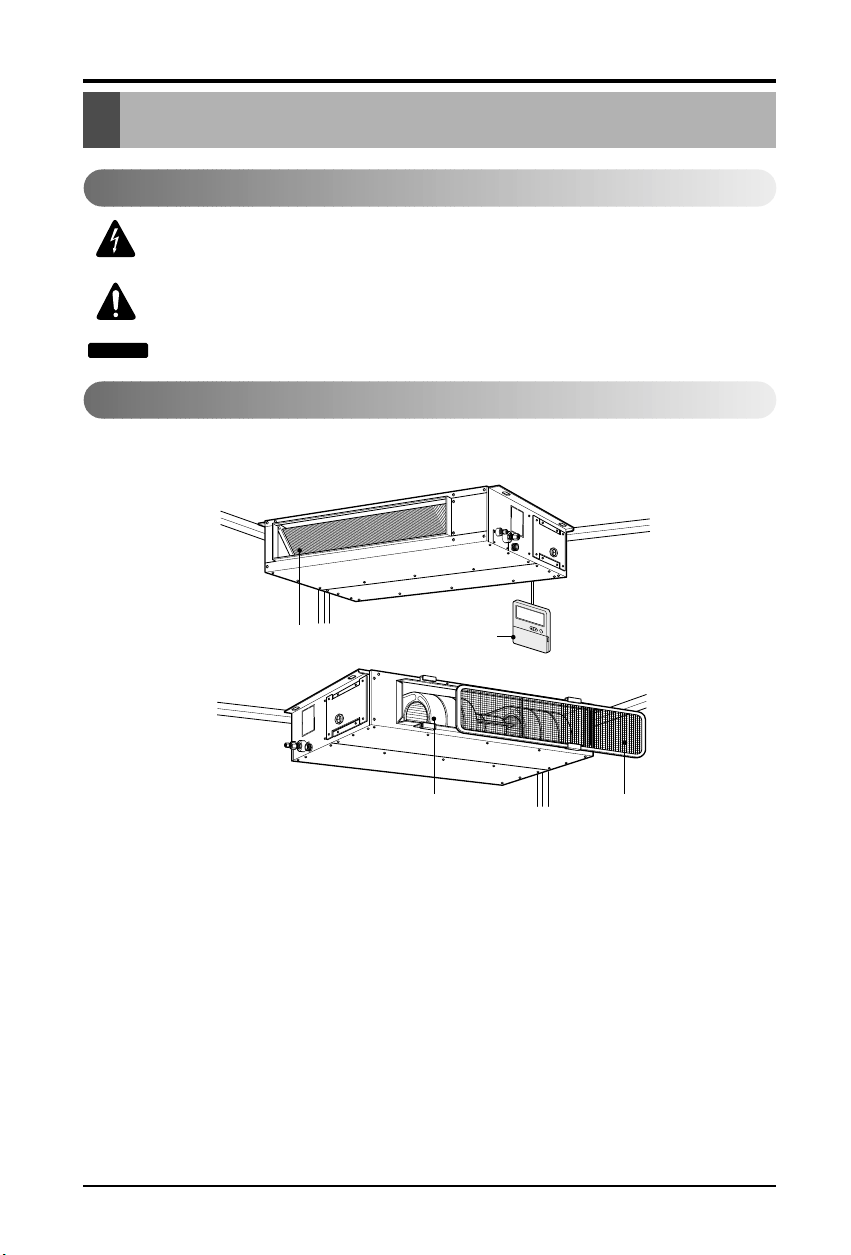
Introduction
Symbols Used in this Manual
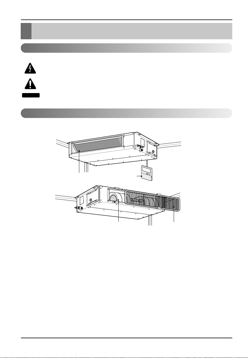
Features
Air filters
Air intake vents
Remote Controller
Air outlet vents
Installation Manual 7
Installation of Indoor
Installation of Indoor
Selection of the best location
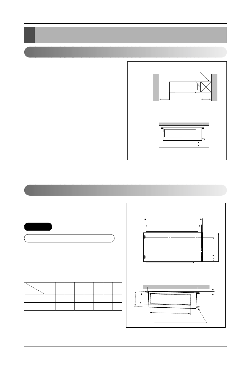
1) Indoor unit
Select location
Install the air conditioner in the location that
satisfies the following conditions.
• The place shall easily bear a load exceeding
four times the indoor unit’sweight.
• The place shall be able to inspect the unit as
the figure.
• The place where the unit shall be leveled.
• The place shall allow easy water
drainage.(Suitable dimension “H” is necessary
to get a slope to drain as figure.)
• The place shall easily connect with the
outdoor unit.
• The place where the unit is not affected by an
electrical noise.
• The place where air circulation in the room will
be good .
• There should not be any heat source or steam
near the unit
H
600600
Top view
(unit: mm)
Front view
Inspection hole
(600X600)
Control box
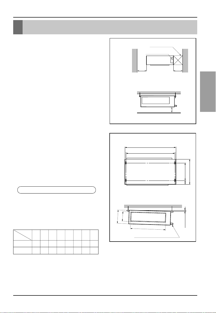
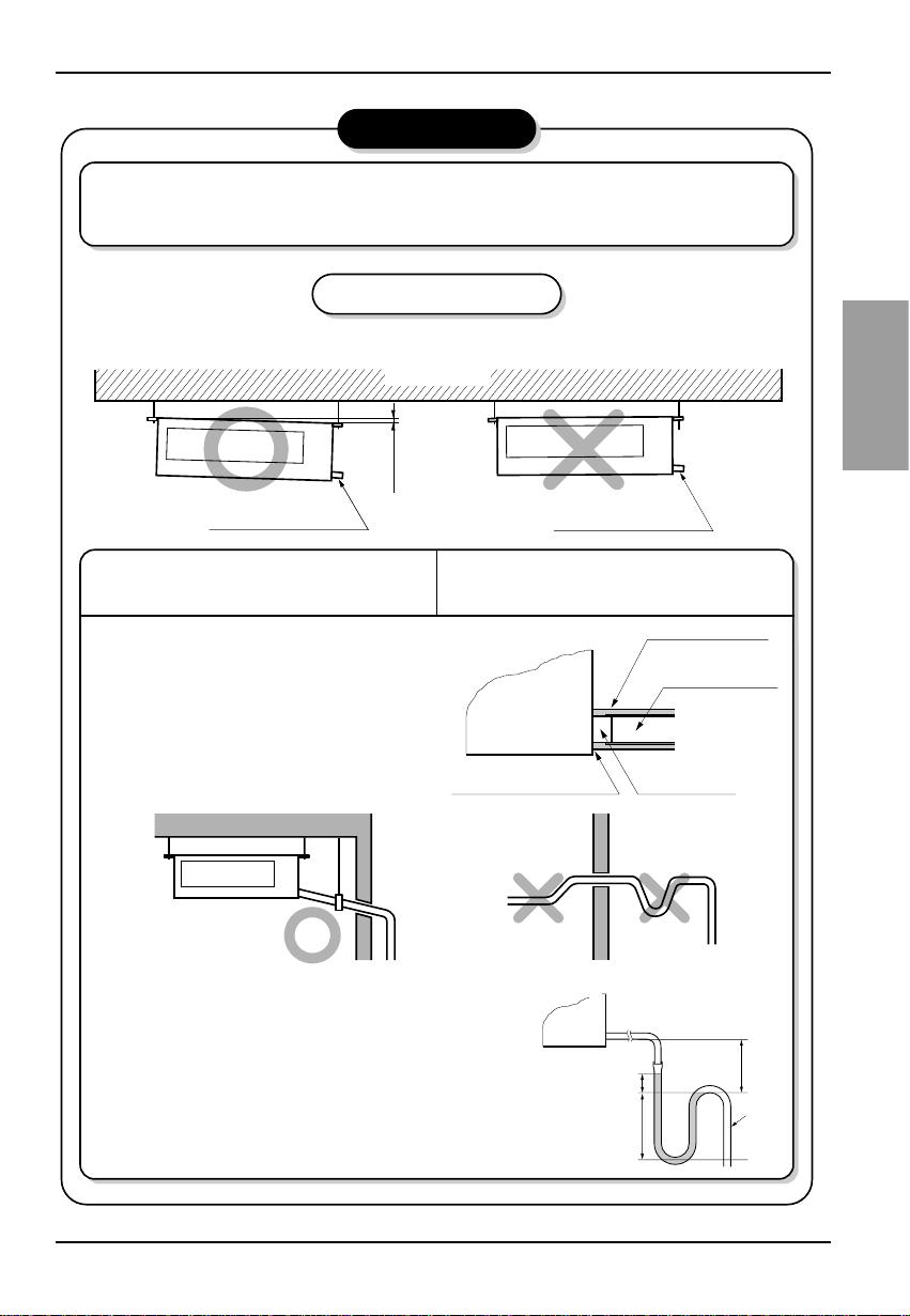
Indoor unit installation
■ Installation of Unit
Install the unit above the ceiling correctly.
• Apply a joint-canvas between the unit and
duct to absorb unnecessary vibration.
• Apply a filter Accessory at air return hole.
CASE 1
POSITION OF SUSPENSION BOLT
(Unit:mm)
9/12K 708 678 434 51 537 455 230 172
18K 1060 1030 434 51 535 805 230 175
Dimension
Capacity
ABCDEFGH
Drainage hole
A
B
CD
1-3 mm
F
H
G
E
8 Multi Type Air Conditioner
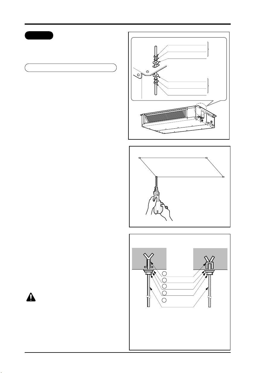
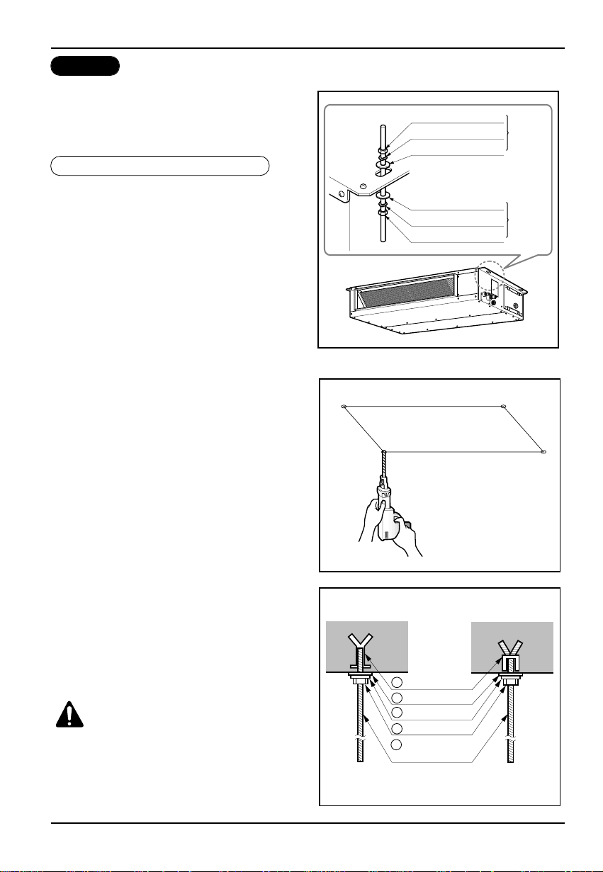
• Select and mark the position for fixing
bolts.
• Drill the hole for set anchor on the face of
ceiling.
• Insert the set anchor and washer onto the
suspension bolts for locking the
suspension bolts on the ceiling.
• Mount the suspension bolts to the set
anchor firmly.
• Secure the installation plates onto the
suspension bolts (adjust level roughly)
using nuts, washers and spring washers.
CAUTION: Tighten the nut and bolt
to prevent unit falling
1 Set anchor
Old building New building
2 Plate washer
3 Spring washer
4 Nut
5 Suspension
bolts
Installation of Indoor
• Install the unit leaning to a drainage hole
side as a figure for easy water drainage.
• A place where the unit will be leveled and
that can support the weight of the unit.
• A place where the unit can withstand its
vibration.
• A place where service can be easily
performed.
CASE 2
POSITION OF CONSOLE BOLT
M10 Nut
M10 SP. washer
M10 washer
X 4
X 4
(Local
supply)
X 4
M10 Nut
M10 SP. washer
M10 washer
X 4
X 4
(Local
supply)
X 4
Installation Manual 9
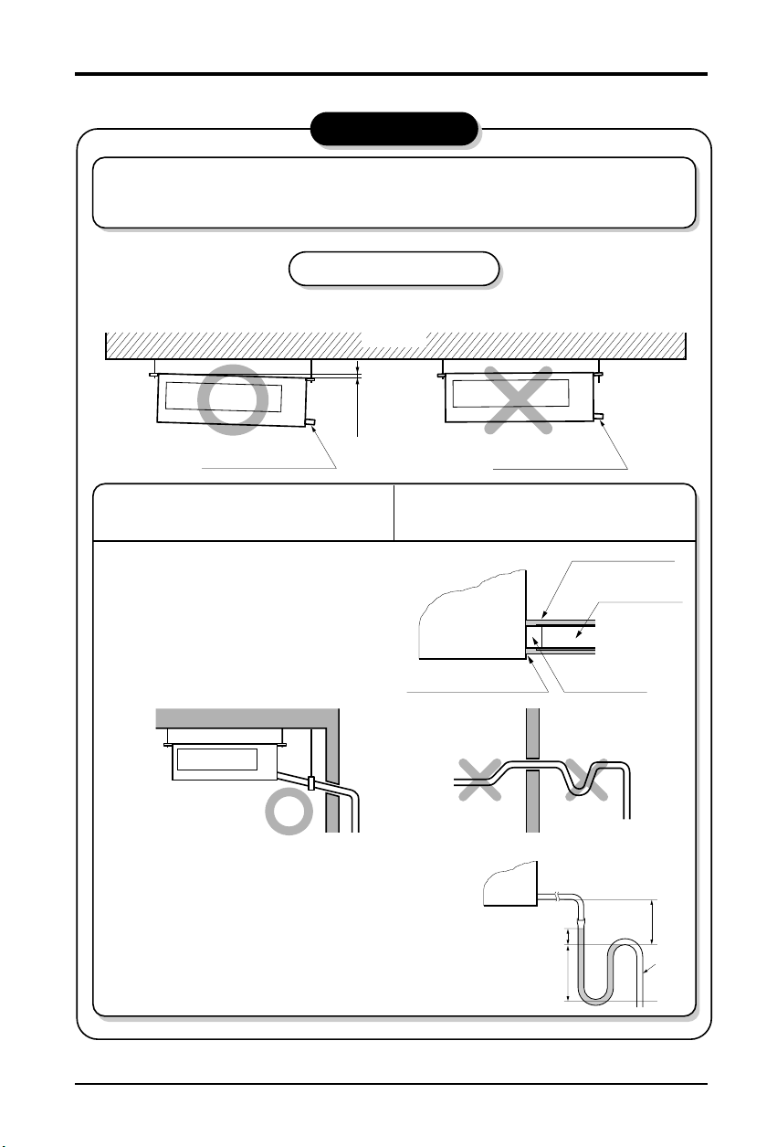
Installation of Indoor
Ceiling
CAUTION
1~3mm
Drainage hole
Drainage hole
U-Trap
B
C
A ≥ 70mm
B ≥ 2C
C ≥ 2 x SP
SP = External Pressure
(mmAq)
Ex) External Pressure
= 10mmAq
A ≥ 70mm
B ≥ 40mm
C ≥ 20mm
A
Make sure to be closed.
Unit
Drainage pipe
(Local supply)
Thermal insulator
(Local supply)
Drainage hole
CAUTION FOR GRADIENT OF
UNIT AND DRAIN PIPING
Lay the drain hose with a downward
inclination so water will drain out.
Front of view
• Always lay the drain with downward
inclination (1/50 to 1/100).
Prevent any upward flow or reverse flow
in any part.
• 5mm or thicker formed thermal insulator
shall always be provided for the drain
pipe.
• Install the P-Trap (or U-Trap) to prevent
a water leakage caused by the blocking
of intake air filter.
Applied U-TrapDimension
1. Install declination of the indoor unit is very important for the drain of the duct type air
conditioner.
2. Minimum thickness of the insulation for the connecting pipe shall be 5mm.
• The unit must be horizontal or declined to the drain hose connected when finished
installation.
CORRECT
CORRECT
INCORRECT
INCORRECT
• Upward routing not
allowed
10 Multi Type Air Conditioner
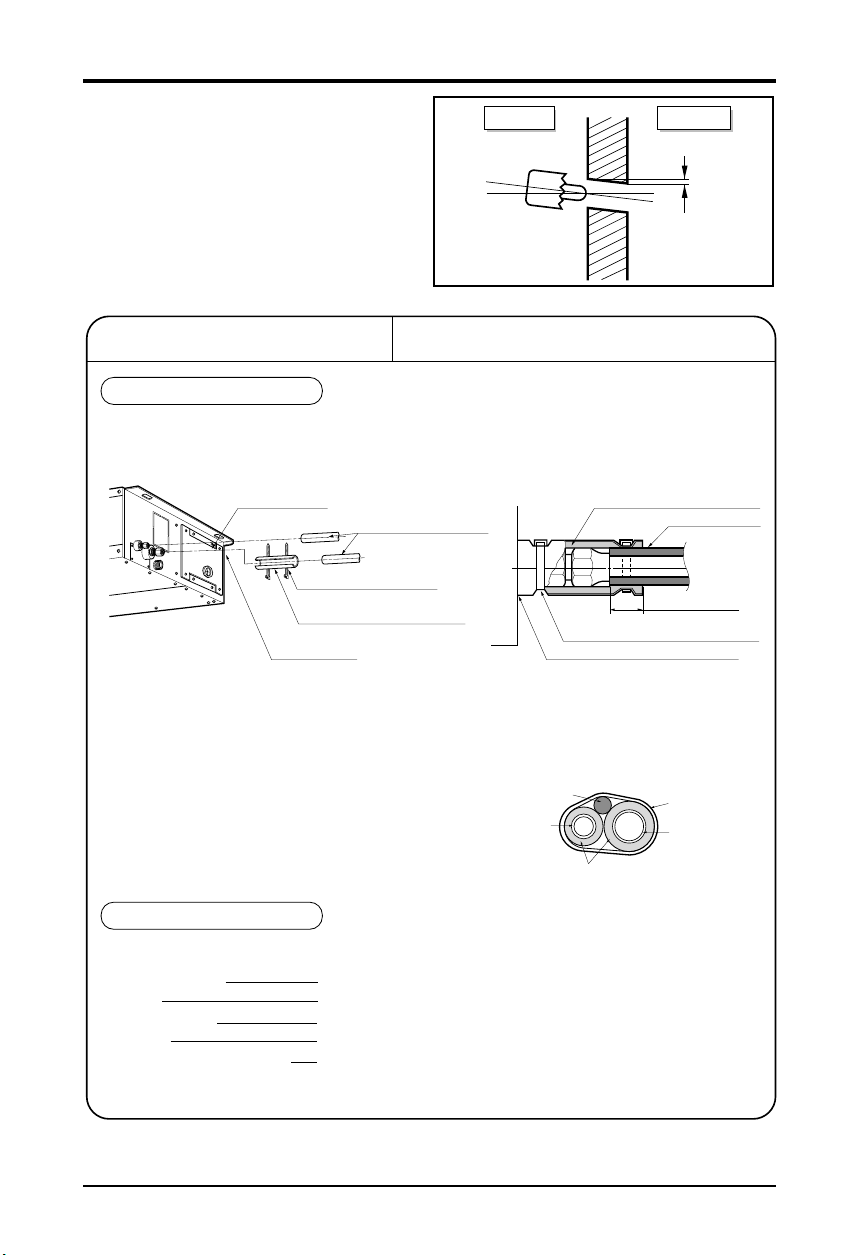
• Drill the piping hole with 70mm dia, hole
core drill.
• Piping hole should be slightly slant to the
outdoor side.
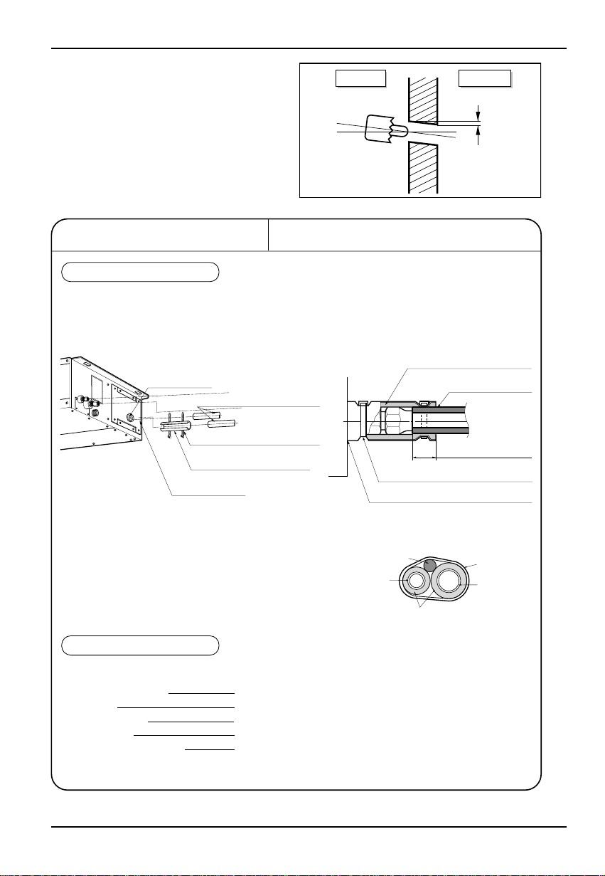
INSULATION, OTHERS
Insulate the joint and tubes completely.
All thermal insulation must comply with local requirement.
INDOOR UNIT
REFRIGERANT PIPE
• Insulate and tape both the gas pipe and
liquid pipe.
■ After all workings are finished, check the working and operation.
• Air distribution Is the air circulation good?
• Drain Is the drainage smoothly and no sweating?
• Gas leakage Is the piping connection correctly?
• Wiring Is the wiring connection correctly?
• Service ValveLock-bolt Is the lock-bolt of Service Valve loosened?
THERMAL INSULATION
TEST AND CHECK
Make sure that there is no clearance here.
Overlap with thermal
insulator for piping.
Thermal insulator for refrigerant pipe
(Local supply)
Thermal insulator for
piping(Local supply)
Hose clip for thermal insulator(Local supply)
Union for liquid pipe
Refrigerant pipe and thermal
insulator(Local supply)
Union for gas pipe
Thermal insulator for refrigerant pipe
(Local supply)
Hose clip for thermal insulator
(Local supply)
Power cable
Liquid pipe
Thermal insulator
Gas pipe
Tape
Installation of Indoor
Indoor Outdoor
WALL
5~7mm
Installation Manual 11
Installation of Indoor
INSTALLATION OF REMOTE CONTROLLER
Install the remote control box
and cord correctly.
• Although the room temperature sensor is in the indoor unit, the remote control box should
be installed in such places away from direct sunlight and high humidity.
INSTALLATION OF THE REMOTE CONTROLLER
• Select places that is not splashed by
water.
• Select control position after receiving
customer approval.
• The room temperature sensor of the
thermostat for temperature control is built
in the indoor unit.
• This remote controller equipped with
liquid crystal display. If this position is
higher or lower,display is difficult to see.
(The standard height is 1.2~1.5m high)
ROUTING OF THE REMOTE CONTROL CORD
• Keep the remote control cord away from
the refrigerant piping and the drain
piping.
• To protect the remote control cord from
electrical noise, place the cord at least
5cm away from other power cables.
(Audio equipment, Television set, etc)
• If the remote control cord is secured to a
wall, provide a trap at the top of the cord
to prevent water droplets from running.
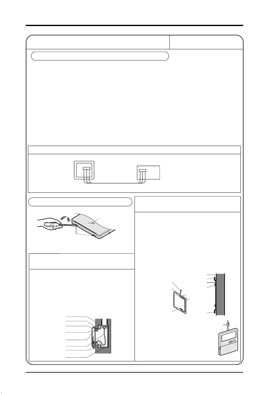
POINT OF REMOTE CONTROLLER INSTALLATION
DISASSEMBLING THE REMOTE CONTROLLER
ELECTRICAL WIRING TO THE INDOOR UNIT
FIXING OF REMOTE
CONTROL CORD
1. Fix the cord clamps on the wall
by ø3 tapping screws(Local supply).
2. Fix the remote control cord.
PROCEDURE OF INSTALLATION
1. Fix the under plate on the switch box by
screws(Local supply). In this case, fit the under
plate on the wall, and be careful of deformation.
2. Receive the remote control cord in the switch box.
3. Hook the remote control unit on the under plate.
WHEN THE REMOTE CONTROLLER IS
INSTALLED WITH THE CORD BURIED.
PROCEDURE OF INSTALLATION
1. Fix the under plate on thewall by self tapping
screws (accessory).
2.Makeaslit(PartA)atthetopsideoftheremote
controller by nipper.
3.Rout the cord as shown in the following figure. In
this case, push the cord into the around of
case(Part B).
4. Hook the remote control unit on the under plate.
WHEN THE REMOTE CONTROLLER IS
INSTALLED WITH THE CORD EXPOSED.
Remote controller
CN REMO
If the length of the cord exceeds 50m, use a wire size greater than 0.5mm
The maximum length of the cord is 100m.
(Main board)
CN REMO
Make sure that wire and terminal
numbers are matched on unit side
and remote controller side.
2
.
Front case
lo
w
e
r p
a
rt
Remote
control
box body
Lever carefully
the box open
using a screw
driver, etc.
T
h
e
Face of wall
Upper notch
Under plate
Remote
control unit
Screw
(Local supply)
Remote
control cord
Lower notch
Switch box
(Local supply)
Remote
control cord
(Part A)
Remote
control unit
Face of wall
Upper notch
Under plate
Tapping screw
(Local supply)
Upper flange
Push hand
(Part B)
Lower notch
Cord
clamp
12 Multi Type Air Conditioner
Connecting Pipes to the Indoor Unit
Connecting Pipes to the Indoor Unit
Preparation of Piping
Main cause of gas leakage is defect in flaring
work. Carry out correct flaring work in the
following procedure.
1) Cut the pipes and the cable.
■ Use the accessory piping kit or the pipes
purchased locally.
■ Measure the distance between the indoor
and the outdoor unit.
■ Cut the pipes a little longer than
measured distance.
■ Cut the cable 1.5m longer than the pipe
length.
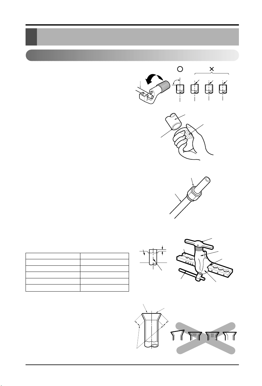
2) Burrs removal
■ Completely remove all burrs from the cut
cross section of pipe/tube.
■ Put the end of the copper tube/pipe to
downward direction as you remove burrs
in order to avoid to let burrs drop in the
tubing.
3) Putting nut on
■ Remove flare nuts attached to indoor and
outdoor units, than put them on pipe/tube
having completed burr removal.
(Not possible to put them on after flaring
work)
4) Flaring work
■ Carry out flaring work using flaring tool
as shown below.
Firmly hold copper tube in a bar(or die) as
indicated dimension in the table above.
5) Check
■ Compare the flared work with figure.
■ If flare is noted to be defective, cut off the
flared section and do flaring work again.
Copper
tube
90°
Slanted Uneven Rough
Pipe
Reamer
Point down
Flare nut
Copper tube
Bar
Copper pipe
Clamp handle
Red arrow mark
Cone
Yoke
Handle
Bar
"A"
Inclined
Inside is shining without scratches.
Smooth all round
Even length
all round
Surface
damaged
Cracked Uneven
thickness
= Improper flaring =
Outside Diameter "A"
1/4" 0~0.5
3/8" 0.5~0.8
1/2" 0.5~0.8
5/8" 0.8~1.0
3/4" 1.0~1.3
Installation Manual 13
Connecting Pipes to the Indoor Unit
6) Pipe bending
Annealed copper pipe with small diameter (ø6.35 or ø9.52) can be easily bent manually. In
this case, secure large R(radius) for the bend section and gradually bend pipe. If annealed
copper pipe is large in diameter (ø15.88 or ø19.05), bend pipe with bender. Use bender
appropriate for the pipe diameter.
7)
Brazing
In refrigerant piping, bending (in particular, acute bending) must be minimized to reduce
piping resistance. Bending is, however, necessary in some places by virtue of the installation
position of devices auxiliary to the packaged air conditioner,or of the building structure,
piping distance or finishing appearance. If a more acute bend is required than that attainable
by pipe bender,perform brazing using ready-made elbow. Aside from this function, brazing
also serves to connect straight pipes, generally using ready-made sockets. While brazing,
protect piping against heat with wet cloth to avoid damaging valve packing or burning
thermal insulator with burner heat. While brazing, blow inert gas (nitrogen gas or carbonic
gas) to prevent formation of oxidation film in copper piping; otherwise, the refrigerant circuit
will clog. The blowing of nitrogen gas (or carbonic gas) through 3-way valves is described in
the following:
8)
Refrigerant piping(Flare piping)
When connecting piping, be sure to keep piping dry(keep piping awayfrom water), clean
(keep piping away from dust) and airtight (avoid refrigerant leakage).
When connecting piping on rainy days or making a through-hole in wall, take due care to
prevent water or plaster from entering piping.
CAUTION: This procedure is
designed to prevent formation of
oxidation film by filling piping with
inert gas. Note that excessive gas
pressure will generate pinholes at
brazed points.
(Nitrogen gas: Supply pressure
0.05~0.1kg/cm2G)
When supplying inert gas, be sure
to open one end of piping.
Water enters Plaster enters
14 Multi Type Air Conditioner
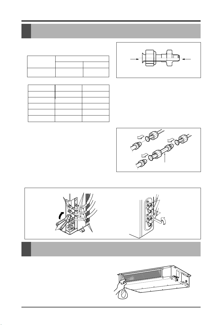
1) Checking the Drainage
1. Check the drainage.
• Spray one or two glasses of water upon
the evaporator.
• Ensure that water flows drain hose of
indoor unit without any leakage.
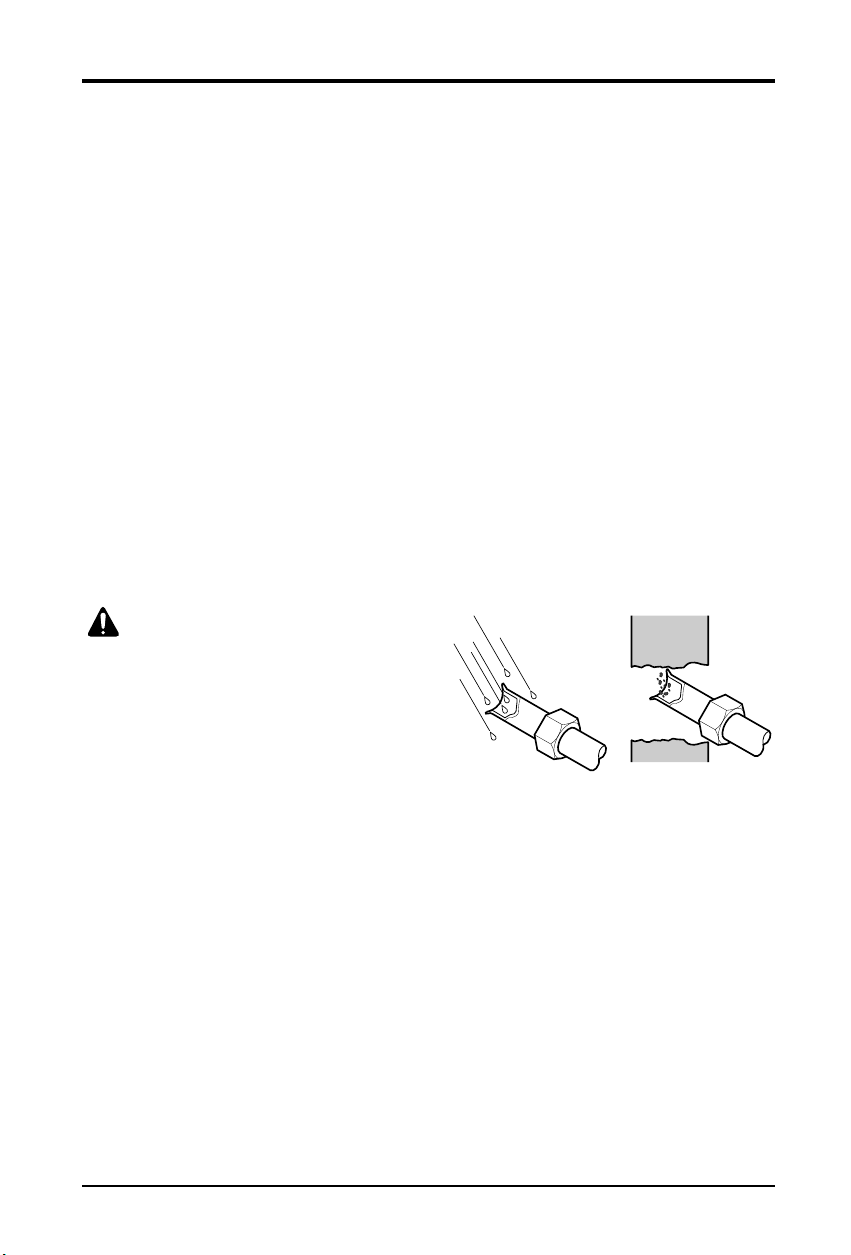
1. When piping installation work you
must be used the connector.
2. Align the center of the pipings and
sufficiently tighten the flare nut by
hand
3. Finally, tighten the flare nut with
torque wrench until the wrench
clicks.
■ When tightening the flare nut with torque
wrench, ensure the direction for tightening
follows the arrow on the wrench.
Connecting Pipes to the Outdoor Unit
Connecting Pipes to the Outdoor Unit
Checking the Drainage
Indoor Units Gas side Liquid side
7K Ø9.52(3/8") Ø6.35(1/4")
9K Ø9.52(3/8") Ø6.35(1/4")
12K Ø9.52(3/8") Ø6.35(1/4")
18K Ø12.7(1/2") Ø6.35(1/4")
24K Ø12.7(1/2") Ø6.35(1/4")
Indoor Units
Gas
AB
Ø9.52 Ø12.7
A
B
*Connecting pipe size
Outdoor unit Outdoor unit
Connector
Liquid side piping
A-UNIT
B-UNIT
C-UNIT
Connector
A-UNIT
Gas side piping
B-UNIT
Liquid side piping
Torque
wrench
Torque wrench
Gas side piping
Installation Manual 15
Connecting Cables between Indoor Unit and Outdoor Unit
Connecting Cables between Indoor Unit
2) Clamping of cables
1) Arrange 2 power cables on the control panel.
2) First, fasten the steel clamp with a screw to the inner boss of control panel.
3) For the cooling model, fix the other side of the clamp with a screw strongly.
For the heat pump model, put the 0.75mm2cable(thinner cable) on the clamp and tighten it
with a plastic clamp to the other boss of the control panel.
4) In Australia, the length of powersupply cord measured from the entryof the power supply
cord to the middle of live pin on the power plug should be over 1.8m.
WARNING: Make sure that the screws of the terminal are free from looseness.
CAUTION: The power cord connected to the outdoor
unit should be complied with the following
specifications (Rubber insulation, type H05RN-F
approved by HAR or SAA).
The connecting cable connected to the indoor and
outdoor unit should be complied with the following
specifications (Rubber insulation, type H07RN-F
approved by HAR or SAA).
NORMAL
CROSS-SECTIONAL
AREA 2.5mm
2
ø8.5mm
GN/YL
20mm
NORMAL
CROSS-SECTIONAL
AREA 0.75mm
2
ø7.5mm
GN/YL
20mm
Connect the cable to the indoor unit by connecting the wires to the terminals on the
control board individually according to the outdoor unit connection. (Ensure that the color
of the wires of the outdoor unit and the terminal No. are the same as those of the indoor unit.)
The earth wire should be longer than the common wires.
The circuit diagram is not subject to change without notice.
When installing, refer to the circuit diagram behind the panel front of Indoor Unit the
wiring diagram on the Control Cover Inside Outdoor Unit.
Connect the cable to the Indoor unit.
CAUTION:
• The circuit diagram is not subject to change without notice.
• Be sure to connect wires according to the wiring diagram.
• Connect the wires firmly, so that not to be pulled out easily.
• Connect the wires according to color codes by referring the wiring diagram.
Air
Conditioner
Main power source
Circuit Breaker
Use a circuit breaker
or time delay fuse.
CAUTION: Provide a circuit
breaker between power source
and the unit as shown below.
16 Multi Type Air Conditioner
Connecting Cables between Indoor Unit
CAUTION:
After the confirmation of the above conditions, prepare the wiring as follows:
1. Never fail to have an individual power specialized for the air conditioner. As for the
method of wiring, be guided by the circuit diagram pasted on the inside of control box
cover.
2. Provide a circuit breaker switch between power source and the unit.
3. The screw which fasten the wiring in the casing of electrical fittings are liable to come
loose from vibrations to which the unit is subjected during the course of
transportation. Check them and make sure that they are all tightly fastened. (If they
are loose, it could give rise to burn-out of the wires.)
4. Specification of power source
5. Confirm that electrical capacity is sufficient.
6. Be sure that the starting voltage is maintained at more than 90 percent of the rated
voltage marked on the name plate.
7. Confirm that the cable thickness is as specified in the power sources specification.
(Particularly note the relation between cable length and thickness.)
8. Never fail to equip a leakage breaker where it is wet or moist.
9. The following troubles would be caused by voltage drop-down.
• Vibration of a magnetic switch, damage on the contact point there of, fuse breaking,
disturbance to the normal function of a overload protection device.
• Proper starting power is not given to the compressor.
Installation Manual 17
Air Purging of the Connecting Pipes and the Indoor Unit
Group Control
Two Thermistor system
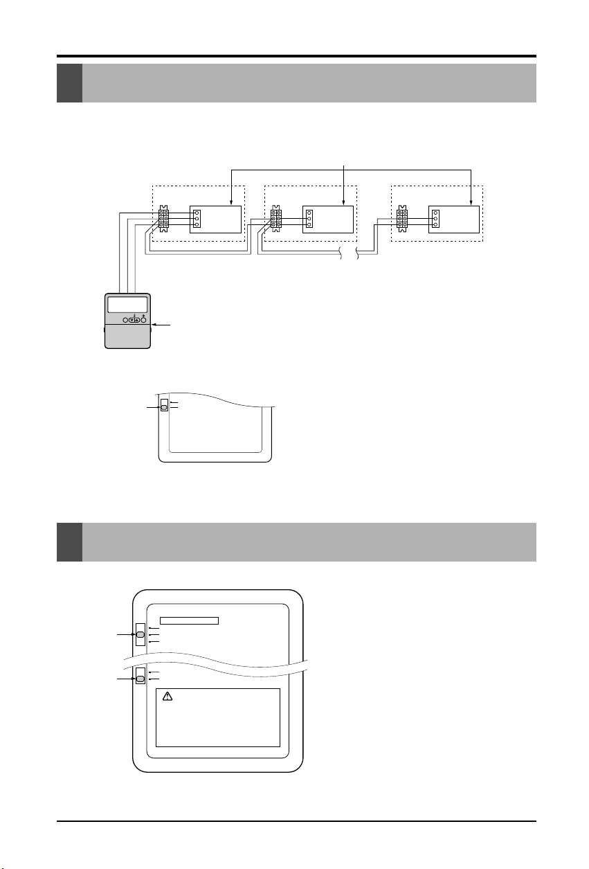
It operates maximum 16 Units by only one Wired Remote Controller,
and each Unit starts sequentially to prevent overcurrent.
• Open the rear cover of Remote
Controller to set up the mode.
•
Selectable options are three as follows
.
- Remo: Sensing the room Temperature.
- Indoor Unit: Sensing the intake air into
indoor Unit.
- 2 TH: Sensing the lower temperature of
the two thermistors.
• To set up the mode, adjust the slide
switch to desired mode position on
installing.
Operation unit
ZONE
1234
Humidify
JET
AUTO
AUTO SWING OPERATION
FAN SPEED
Program set
SUB FUNCTION
SET TEMP
Room Temp
HI
MED
LO
Heater
Defrost
Filter
Preheat
Out door
Time
Timer
On
Set no.Time
Off
01 03 0507 09 11 13 15 1719 21 23
Indoor Unit 1
Terminal(Local Supply)
Block
Terminal(Local Supply)
Block
Terminal(Local Supply)
Block
Main PCB
#1
Main PCB
#2
Main PCB
#16
Wired Remote Controller
(Standard)
Indoor Unit 2
Main PCB
Indoor Unit 16
Connector
RED(12V)
YL(SIGNAL)
BR(GND)
RED(12V)
YL(SIGNAL)
BR(GND)
YL(SIGNAL)
BR(GND)
Connecting Cable(Local Supply)
Connector Connector
....
....
YL(SIGNAL)
BR(GND)
YL(SIGNAL)
BR(GND)
YL(SIGNAL)
BR(GND)
Remote
Controller
PCB
Single
Group
Slide Switch2
Slide Switch1
Remo.
Room Temp . Sensing
Indoor Unit
2 TH(Remo.+Indoor)
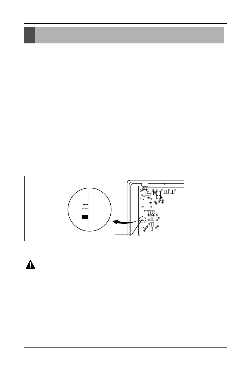
• On installing, don't impact to the PCB
and LCD display.
• Don't remove the protection sheet.
• Use the specified screw.
• On installing, turn off the main power.
CAUTION
Single
Group
Slide Switch2
• Using the supplied Wired Remote Controller,
wire them like above.
• Move slide switch2 to "Group" position.
• Ensure that the color of wire.
18 Multi Type Air Conditioner
E.S.P.(External Static Pressure) Setting
(1) Open the rear cover of the wired remote-controller to set the mode.
(2) Select one of three selectable modes as follows.
■ Without Zone System
1. PositionV-H, F-H:
• This position sets the maximum E.S.P as a default set.
2. PositionV-L:
• This position sets the minimum E.S.P as a default set.
■ With Zone System
1. PositionV-H:
• Maximum E.S.P setting & Fan speed is varied according to the state of dampers by micom.
2. PositionF-H:
• Maximum E.S.P setting & Fan speed doesn't vary according to the opening & Closing of dampers.
3. PositionV-L:
• Minimum E.S.P setting & Fan speed is varied according to the state of dampers by micom.
*Maximum : 3mmAq
Minimum : All-0mmAq
(3) Move the slide switch to set position.
(4) Close the rear cover and check if it works normally.
TH
R14H
SW TH
REMO
MAIN
2TH
OP7
R18H
R17H
OP6
LO
STAND
SW HIGH
HI
R03S
C070
R04S
R02S
R01S
OP3
OP2 OP1
R19H
R11H
R13H R12H
OP5R16H OP4
R15H
CO1H
V-L
V-H
F-H
Slide switch for ceiling height
CAUTION: Select the position after checking duct work and E.S.P of the unit.
Maunfactured in the position F-H.
E.S.P.(External Static Pressure) Setting
Installation Manual 19
How to Set E.S.P?
Preheat
ZONE
Operation unit Program set
Room Temp
MED
LO
AUTO
JET
Heater
Defrost
Filter
Humidify
Out door
Timer
On
Set no. Time
Off
01 03 05 07 09 11 13 15 17 19 21 23
1234
OPERATION
FAN SPEED
SUB FUNCTION
SET TEMP
HI
AUTO SWING
Time
Preheat
ZONE
Operation unit Program set
Room Temp
MED
LO
AUTO
JET
Heater
Defrost
Filter
Humidify
Out door
Timer
On
Set no. Time
Off
01 03 05 07 09 11 13 15 17 19 21 23
1234
OPERATION
FAN SPEED
SUB FUNCTION
SET TEMP
HI
AUTO SWING
Time
Time
SUB FUNCTION
SET TEMP
OPERATIONAUTO SWING
Preheat
ZONE
Operation unit Program set
Room Temp
MED
LO
AUTO
JET
Heater
Defrost
Filter
Humidify
Out door
Timer
On
Set no. Time
Off
01 03 05 07 09 11 13 15 17 19 21 23
1234
FAN SPEED
HI
Time
SUB FUNCTION
SET TEMP
OPERATIONAUTO SWING
Preheat
ZONE
Operation unit Program set
Room Temp
MED
LO
AUTO
JET
Heater
Defrost
Filter
Humidify
Out door
Timer
On
Set no. Time
Off
01 03 05 07 09 11 13 15 17 19 21 23
134
FAN SPEED
HI
2
Timer
1
2
3
5
4
Timer
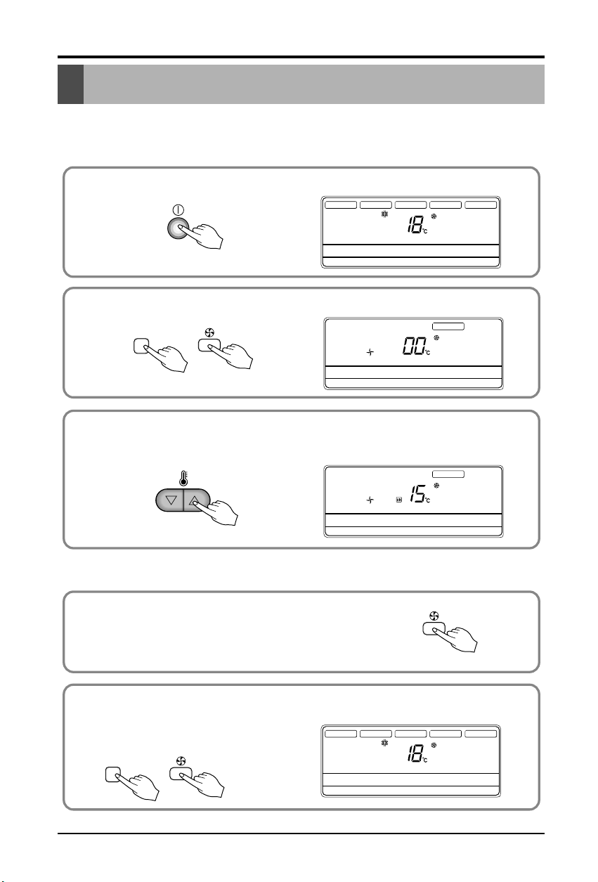
Procedure of RPM change:
Ex) External Static pressure is 1mmAq for "9k"
• To protect the unit, compressor is designed to be off during E.S.P. setting.
Push the "On/Off" button.
The unit will start.
Push the "Timer" and "Wind" button simultaneously for more then 3 seconds.
Push the "Up" of "Down" button for E.S.P adjustment.
And, adjust the number which you want.(In this example, the number is "215". Refer to the
table 1 on the next page.)
Shift the fan speed mode bypressing the fan speed button.
And then, Adjust numbers of next steps by repeating the stage 3.
(In this example, the numbers are "235" and "250" respectly)
Push the "Timer" and "Wind" button simultaneously for more than 3 seconds.
Then, Wind Data is memorized by the EEPROM of the main PCB.
Note: The range of selection is from 1~254. Since, the display is two Digit only.
If the range selection is above100 then the third digit will appear in the screen as shown.
How to Set E.S.P?
20 Multi Type Air Conditioner
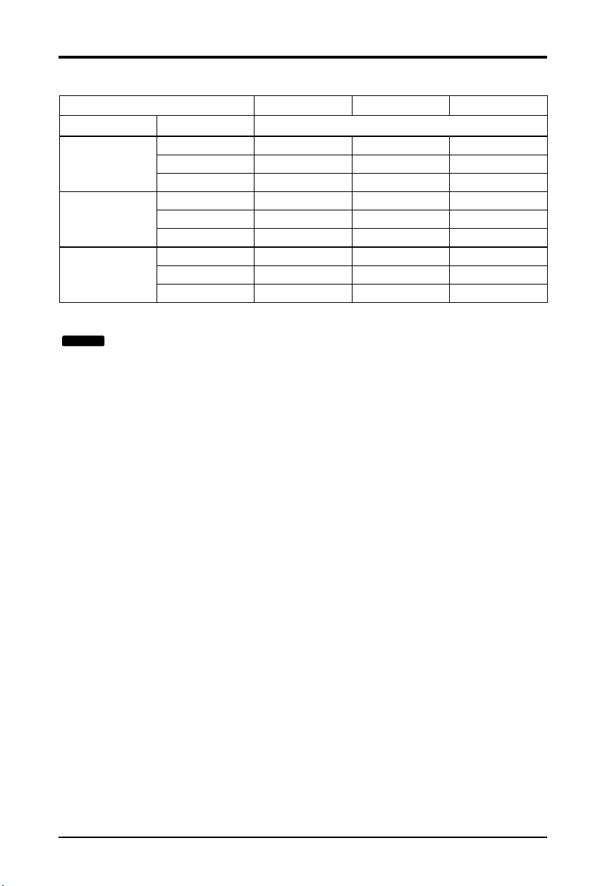
Static Pressure(mmAq)
Setting Value
012
Ca(Btu/h) Step(Hi/Med/Lo)
8 CMM 220 215 210
9k 7 CMM 240 235 230
6 CMM 255 250 245
10 CMM 175 170 150
12k 9CMM 200 190 185
8 CMM 220 215 210
14 CMM 170 150 130
18k 13 CMM 185 165 145
12 CMM 200 180 160
[Table. 1]
: 1. Be sure to set the value refering table 1. Unexpected set value will cause
mal-function.
2. Table 1 is based at 230V. According to the fluctuation of voltage, air flow
rate varies.
NOTICE
How to Set E.S.P?

ITALIANOITALIANO
LG
Condizionatore d’aria di tipo da
controsoffitto a socmparsa
MANUALE D’INSTALLAZIONE
IMPORTANTE
• Leggere questo manuale d’istruzioni prima di installare il
condizionatore d’aria.
• Il lavoro d’installazione deve essere eseguito conformemente
alla normativa vigente sugli impianti elettrici, solo da
personale tecnico autorizzato.
• Dopo averlo letto dettagliatamente, conservare questo
manuale come riferimento per il futuro

2 Climatizzatore tipo da controsoffitto a socmparsa
Climatizzatore tipo da controsoffitto a socmparsa Manuale d’installazione
INDICE
Precauzioni di sicurezza.............................................3
Introduzione.................................................................6
Installazione dellunità Intern......................................7
Collegamento dei tubi al Gruppo Interno...............12
Collegamento dei tubi al Gruppo Esterno..............14
Controllo dello Scarico.............................................14
Collegamento del cavo tra unità interna e unità
esterna........................................................................15
Controllo di gruppo...................................................17
Sistema a due termistori ..........................................17
Comment régler E.S.P (Pression statique externe....
....................................................................................18
Impostazione P.S.E (Pressione Statica Esterna)? ....
....................................................................................19
❏ Indicatore di livello
❏ Cacciavite
❏ Trapano elettrico
❏ Trapano per carotaggio (ø 70 mm)
❏ Metro orizzontale
❏ Setdistrumentipersvasatura
❏ Coppie di serraggio specificate
1,8 kgm, 4,2 kgm, 5,5 kgm, 6,6 kgm
(differenti a seconda del n°.di modello)
❏ Chiave.............Semi-raccordo
❏ Un bicchiere d'acqua
❏ Cacciavite
❏ Chiave esagonale (4mm/5mm)
❏ Rilevatore di fughe di gas
❏ Pompa a vuoto
❏ Manometro
❏ Manuale dell’utente
❏ Termometro
❏ Supporto del telecomando
Requisiti di installazione
Elementi richiesti
Precauzioni di sicurezza
Manuale d’installazione
3
ITALIANO
Per evitare infortuni dell'utente o altre persone e danni alle cose, attenersi alle seguenti
istruzioni.
■
L’uso errato causato dalla mancata osservanza delle istruzioni può causare danni o lesioni.
L’importanza è classificata dalle seguenti indicazioni.
■ Il significato dei simboli utilizzati in questo manuale è spiegato di seguito.
Questo simbolo indica la possibilità di decesso o di grave infortunio.
Questo simbolo indica la possibilità di infortunio o danni alle cose.
ATTENZIONE
Azione/operazione da non fare.
Attenersi alle istruzioni.
Precauzioni di sicurezza
■ Installazione
Installare il pannello e il
coperchio della scatola di
controllo in modo sicuro.
• Vi è il rischio di scosse elettriche o
incendio.
Installare sempre un
interruttore automatico e
circuito dedicato
• L'errato cablaggio o installazione può
causare incendi o scosse elettriche.
Utilizzare fusibili o interruttori
automatici di giusta tensione.
• Vi e il rischio di scosse elettriche o
incendio.
Non utilizzare interruttori automatici
difettosi o di potenza inferiore.
Utilizzare questa apparecchiatura su
un circuito dedicato.
• Vi è il rischio di scosse elettriche o
incendio.
Per i collegamenti elettrici, rivolgersi
al rivenditore, a un elettricista
qualificato o a un centro di
assistenza autorizzato.
• Non smontare o tentare di riparare il
prodotto.Vi è il rischio di scosse
elettriche o incendio.
Il prodotto deve essere sempre
provvisto di messa a terra.
• Vi è il rischio di scosse elettriche o
incendio.
ATTENZIONE
AVVISO
4 Climatizzatore tipo da controsoffitto a socmparsa
Precauzioni di sicurezza
Nonmodificareoprolungareilcavodi
alimentazione.
• Vi è il rischio di scosse elettriche o incendio.
Disimballare e installare il prodotto con
attenzione.
•
I bordi taglienti possono causare infortuni. Fare
particolare attenzione ai bordi del contenitore e
alle alette del condensatore e dell'evaporatore.
Per l'installazione, rivolgersi sempre al
rivenditore o a un centro di assistenza
autorizzato.
• Vi è il rischio di scosse elettriche, incendio,
esplosione o lesioni.
Non installare il prodotto su supporti di
installazione difettosi.
• Ciò potrebbe causare infortuni, incidenti o
danni al prodotto.
Accertarsi che l'area di installazione non sia
soggetta a deterioramento nel tempo.
•
Se la base si rompe, l’unità può cadere con essa,
causando infortuni a persone, guasti al prodotto o danni
alle cose.
Non utilizzare il prodotto troppo a lungo in
ambienti molto umidi e con una finestra o una
porta aperta.
• L’umidità potrebbe condensarsi e bagnare o
danneggiare i mobili.
Non conservare o utilizzare gas infiammabili o combustibili in prossimità del prodotto.
• Vi è il rischio di incendio o guasti al prodotto.
■ Funzionamento
asolin
G
Manuale d’installazione
5
ITALIANO
Precauzioni di sicurezza
Dopo l'installazione o la riparazione del
prodotto, verificare sempre che non vi siano
perdite di gas (refrigerante).
• Livelli bassi di refrigerante potrebbero
causare guasti al prodotto.
Installare il tubo flessibile di scarico in modo da
garantire uno scarico corretto e sicuro.
• Un errato collegamento può causare perdite
d’acqua.
Installare il prodotto allineandolo in modo
uniforme.
• Per evitare perdite d'acqua.
Non installare il prodotto in modo che il rumore
ol’aria calda provenienti dall’unità esterna
possano causare danni ai vicini.
• Ciò potrebbe causare problemi con i vicini.
Per sollevare e trasportare il prodotto sono
consigliabili due persone.
• Evitare lesioni personali.
Non installare il prodotto in luoghi esposti
direttamente al vento di mare (spruzzi di sale).
• Ciò potrebbe causare corrosioni al prodotto.
La corrosione, in particolare sul condensatore
e sulle alette dell’evaporatore, può causare
malfunzionamenti o inefficienza.
AVVISO
■ Installazione
90˚
6 Climatizzatore tipo da controsoffitto a socmparsa
Introduzione
Simboli usati in questo manuale
Questo simbolo segnala il rischio di scossa elettrica.
Questo simbolo segnala i pericoli che potrebbero causare danni al
condizionatore d'aria.
Questo simbolo indica note speciali
AVVISO
Caratteristiche
Filtri aria
Prese d’aria di uscita
Prese d’aria di entrata
Telecomando
Introduzione
Installazione dellunità Interna
Manuale d’installazione
7
ITALIANO
Installazione dellunità Interna
1. Selezione della migliore posizione
1) Gruppo Interno
Selezione della posizione
Installare il condizionatore d’aria nel punto che soddisfa le
seguenti condizioni.
•
Il punto può facilmente sostenere quattro volte il peso del
gruppo interno.
•
In questo punto sarà agevole ispezionare il gruppo come
indicato dall’illustrazione.
•
Un punto in cui il gruppo sarà messo a livello.
•
Un punto che permetta un agevole scarico dell’acqua. (Le
dimensioni idonee “H” sono necessarie per ottenere una
curva per scaricare come dall’illustrazione.
•
Un punto in cui sia agevole effettuare il collegamento con
il gruppo esterno.
•
Un punto in cui il gruppo non sia influenzato da rumore
elettrico.
•
Un punto in cui la circolazione di aria nella stanza sia
buona.
•
L’assenza di fonti di calore o vapore nelle vicinanze del
gruppo.
2.Installazione del Gruppo Interno
■ Installazione del Gruppo
Installare correttamente sul soffitto
• Applicare un giunto gommato tra gruppo e
conduttura al fine di assorbire le vibrazioni
inutili.
• Applicare un accessorio filtro sul foro di
ritorno dell’aria
H
600600
Vista superiore
(unità: mm)
Vista frontale
Foro di ispezione
(600X600)
Scatola di controllo
POSIZIONE DEL BULLONE DI SOSPENSIONE
(Unit:mm)
Foro di scarico
A
B
CD
1-3 mm
F
H
G
E
9/12K 708 678 434 51 537 455 230 172
18K 1060 1030 434 51 535 805 230 175
Dimensioni
Capacità
ABCDEFGH
8 Climatizzatore tipo da controsoffitto a socmparsa
Installazione dellunità Interna
• Installare il gruppo in pendenza verso il
foro di scarico come indicato dalla figura
per facilitare lo scarico dell’acqua.
• Un punto dove il gruppo è a livello e può
sostenere il peso del gruppo.
• Un punto in cui il gruppo può sostenere
le vibrazioni
• Un punto che sia facile da raggiungere
per la manutenzione.
CASO 2
POSIZIONE DEL BULLONE DELLA CONSOLLE
Dado
M10
Dado
M10
Rondella Dist M10 SP
Rondella Dist. M10
Rondella M10
Rondella M10
X 4
X 4
(Fornitura
locale)
(Fornitura
locale)
X 4
X 4
X 4
X 4
1 Ancoraggio
Costruzione
vecchia
Costruzione
nuova
2 Rondella piastra
3 Rondella elastica
4 Dado
5 Bullone di
sospensione
• Selezionare e contrassegnare la
posizione di fissaggio dei bulloni.
• Praticare un foro per inserire gli
ancoraggi sul soffitto.
• Inserire l’ancoraggio e la rondella sui
bulloni di sospensione per bloccare i
bulloni di sospensione al soffitto.
• Montare i bulloni di sospensione per
ancorare saldamente.
• Fissare le piastre di installazione sui
bulloni di sospensione (regolare il livello
a occhio) usando dadi, rondelle e
rondelle elastiche.
AVVISO
: Stringere il dado e bullone per evitare
la caduta del gruppo.
Manuale d’installazione
9
ITALIANO
Installazione dellunità Interna
SOFFITTO
ATTENZIONE
Foro di scarico
Foro di scarico
Sifone a U
B
C
A ≥ 70mm
B ≥ 2C
C ≥ 2 x SP
SP = Pressione esterna
(mmAq)
Es) Pressione esterna
= 10mmAq
A ≥ 70mm
B ≥ 40mm
C ≥ 20mm
A
Verificare che sia chiuso
Gruppo
Foro di scarico
ATTENZIONE PER LA PENDENZA
DI UNITÀTUBATURA DI SCARICO
Disporre il tubo flessibile di scarico con
una inclinazione verso il basso per facilitare
los carico dell'acqua.
Tubo di scarico
(Fornitura locale)
Isolatore termico
(Fornitura locale)
1~3mm
Vista di fronte
• Disporre sempre lo scarico con una
inclinazione verso il basso (1/50 a
1/100).
Impedire qualsiasi scorrimento verso
l’alto o inverso in qualsiasi punto.
• Il tubo di scarico deve essere sempre
fornito di isolamento termico sagomato
dello spessore di 5mm o superiore.
• Installare il sifone intercettatore a
P (o sifone a U) per prevenire le
perdite di acqua provocate dal
blocco del filtro di aspirazione.
1. La pendenza di installazione del gruppo interno è importante per lo scarico del
condizionatore d’aria del tipo a condotti.
2. Lo spessore minimo dell’isolamento dei tubi di collegamento deve essere di 5 mm.
• Il gruppo deve essere orizzontale o in pendenza verso il tubo di scarico collegato ad
installazione terminata.
CORRETTO
CORRETTO
SCORRETTO
Dimensioni applicate sifone a U
SCORRETTO
• La disposizione del
tubo verso lalto non
è permessa.
10 Climatizzatore tipo da controsoffitto a socmparsa
Installazione dellunità Interna
• Praticare un foro per i tubi con una punta
di 70mm di dia metro.
• Il foro per la tubatura deve essere
leggermente inclinato verso il basso dal
lato esterno.
ISOLAMENTO, ALTRO
Isolare completamente i raccordi ed i tubi.
Tutto l’isolamento termico deve essere conforme ai requisiti
locali.
GRUPPO INTERNO
Tubo refrigerante
Isolare con nastro sia le condutture del
gas che le condutture del liquido.
■ Una volta finito il lavoro, controllare il funzionamento e l’operazione.
• Distribuzione aria La circolazione dell’aria è soddisfacente?
• Scarico Lo scarico è dolce e senza trasudamento?
• Fughe di gas I collegamenti dei tubi sono corretti?
• Cablaggio Le connessioni dei cavi sono corrette?
• Bullone di bloccaggio Il bullone di bloccaggio del compressore è allentato?
ISOLAMENTOTERMICO
COMPROBACIONES
Assicurarsi che non ci sia luce in questa posizione.
Parte sovrapposta con
isolatore termico per tubature
(Fornitura locale)
Isolatore termico per tubo refrigerante
(fornitura locale)
Isolatore termico per tubi
(fornitura locale)
Morsetto per tubo flessibile per isolatore termico
(fornitura locale)
Raccordo per tubo del liquido
Tubo refrigerante e isolatore termico
(fornitura locale)
Raccordo per tubo gas
Isolatore termico per tubo
refrigerante (fornitura locale)
Morsetto per tubo flessibile per isolatore
termico (fornitura locale)
Cavo di alimentazione
Tubo liquido
Isolatore termico
Tubo gas
Nastro
Interno Esterno
MURO
5~7mm

Manuale d’installazione
11
ITALIANO
Installazione dellunità Interna
INSTALLAZIONE DELLA SCATOLA DEL TELECOMANDO
Installare correttamente il cavo e la
scatola di controllo del telecomando.
• Nonostante nel gruppo interno sia presente un sensore della temperatura dell’ambiente, la scatola
del telecomando deve essere installata in punti lontani dalla luce diretta del sole o di alta umidità.
INSTALLAZIONE DELLA SCATOLA DEL TELECOMANDO
• Selezionare punti che non siano sottoposti agli
schizzi d’acqua
• Selezionare una posizione per il controllo dopo
avere ricevuto l’approvazione del cliente.
• Il sensore della temperatura dell’ambiente del
termostato per il controllo della temperatura è
inserito nel gruppo interno.
• Il telecomando è fornito di display a cristalli
liquidi. Se la posizione è troppo alta o troppo
bassa il display sarà difficile da vedere.
(L’altezza standard è 1,2-1,5 m di altezza)
DISPOSIZIONE DEL CAVO DEL TELECOMANDO
• Tenere il cavo del telecomando lontano
dalle tubature refrigeranti e le tubature
di scarico.
• Per schermare il cavo del telecomando
da rumore elettrico, disporre il cavo a 5
cm da altri cavi di alimentazione.
(Attrezzature audio, televisore ecc.)
• Se il cavo del telecomando viene fissato
ad un muro inserire un separatore nella
sezione superiore del cavo per evitare lo
sgocciolare di acqua.
PUNTO DI INSTALLAZIONE DEL TELECOMANDO
SMONTAGGIO DEL TELECOMANDO
CABLAGGIO ELETTRICO DEL GRUPPO INTERNO
FISSAGGIO DEL
CAVO DEL TELECOMANDO
1. Fissare le reggette del cavo sul muro
usando viti autofilettanti del 3ÿ
(fornitura locale)
2. Fissare il cavo del telecomando.
PROCEDURE DI INSTALLAZIONE
1. Fissare la sottopiastra sulla scatola degli interruttori con
delle viti (fornitura locale). In questo caso inserire la
piastra sul muro facendo attenzione a non deformarla.
2. Infilare il cavo del telecomando nella scatola degli
interruttori.
3. Agganciare l’unità del telecomando sulla sottopiastra.
NEL CASO DI INSTALLAZIONE DI SCATOLA DEL
TELECOMANDO CON CAVO INCASSATO
PROCEDURE DI INSTALLAZIONE
1. Fissare la sottopiastra al muro con viti
autofilettanti.
2. Praticare una fessura (Parte A) sul lato
superiore della scatola del telecomando con
una tenaglia.
3. Far passare il cavo come indicato nella figura
che segue. In questo caso premere il cavo
intorno alla scatola (Parte B)
4. Agganciare l’unità del telecomando sulla
sottopiastra
NEL CASO DI INSTALLAZIONE DI SCATOLA
DEL TELECOMANDO CON CAVO A VISTA
Telecomando
CN REMO
Se la lunghezza del cavo supera 50m, usare un filo con sezione superiore a 0,5mm
La lunghezza massima del cavo è 100 m.
(Pannello principale)
CN REMO
Verificare che i numeri di filo e
di terminale siano combinati sul
lato unità e sul lato telecomando.
2
Scatola frontale
io
n
e
in
fe
rio
re
Corpo scatola del
telecomando.
Fare leva con attenzione
usando un cacciavite
per aprire la scatola
S
e
z
Parete
Dentellatura superiore
Sottopiastra
Unità telecomando
Vite (fornitura locale)
Cavo del telecomando
Dentellatura inferiore
Scatola interruttore
Parete
Sottopiastra
Vite autofilettante
(Fornitura locale)
Flangia superiore
Premere
(Parte B)
Dentellatura
inferiore
Morsetto
per cavo
(Parte A)
Unità di
telecomando
Dentellatura Superiore
Cavo del
telecomando

12 Climatizzatore tipo da controsoffitto a socmparsa
Preparazione dei tubi
Collegamento dei tubi al Gruppo Interno
Collegamento dei tubi al Gruppo Interno
La causa principale delle fughe di gas sono difetti
nel lavoro di svasatura. Effettuare correttamente il
lavoro di svasatura seguendo queste istruzioni.
1) Tagliare il tubo e il cavo
■
Usare il corredo per tubi accessorio o i
tubi acquistati localmente.
■
Misurare la distanza tra gruppo interno e
gruppo esterno.
■
Tagliare i tubi in lunghezza leggermente
superiore a quella misurata.
■
Tagliare il cavo 1,5 m più lungo della
lunghezza del tubo.
2) Rimozione delle bavature
■
Rimuovere completamente le bavature
dalla sezione tagliata del tubo.
■
Volgere l’estremità del tubo di rame
verso il basso per evitare la caduta
delle bavature all’interno dei tubi.
3) Inserimento del dado
■
Rimuovere i dadi svasati collegati ai
gruppi interno ed esterno, poi inserirli
sul tubo dopo avere terminato la
rimozione delle bavature. (Non è
possibile inserirli dopo aver effettuato il
lavoro di svasatura.
4) Lavoro di Svasatura
■
Usare l’arnese di svasatura indicato
sotto per effettuare il lavoro di svasatura.
Tenere ben saldo il tubo di rame in una
barra o forma come indicato nella tabella
delle dimensioni riportata in precedenza.
5) Controllo
■
Confrontare il lavoro di svasatura con
l’illustrazione.
■
Se la svasatura sembra difettosa , tagliare
la sezione svasata e rifare la svasatura.
Tubo di rame
90°
Inclinato Impari Grezzo
Tubo
Alesatore
Punta verso
il basso
Dado svasato
Tubo di rame
Barra
Tubo di rame
Manico del morsetto
Freccia rossa
Cono
Morsetto
Manico
Barra
"A"
Inclinato
L'interno lucido senza graffi.
Liscio per tutta la circonferenza
Lunghezza uguale
per tutta la circonferenza
Superficie
danneggiata
Spaccato Spessore
irregolare
=
Svasatura scorretta =
Diametro esterno
"A"
1/4" 0~0.5
3/8" 0.5~0.8
1/2" 0.5~0.8
5/8" 0.8~1.0
3/4" 1.0~1.3

Manuale d’installazione
13
ITALIANO
Collegamento dei tubi al Gruppo Interno
6) Piegatura dei tubi
I tubi di rame ricotto di piccolo diametro (ø 6,35 0 ø 9,52) possono essere facilmente piegati
manualmente. In questo caso fermare un R (raggio) ampio per la sezione da piegare e
piegare gradualmente il tubo. Se il tubo di rame ricotto è di diametro grande (ø 15,88 o
ø 19,05) piegare il tubo con un piegatubi. Usare il piegatubi adeguato al diametro del tubo.
7) Brasatura
Nelle tubature del refrigerante la piegatura deve essere minimizzata (ed in particolare
piegature ad angoli acuti) al fine di ridurre la resistenza delle tubature. Comunque, la
piegatura è necessaria in alcuni punti a causa della posizione di dispositivi ausiliari al
condizionatore d’aria o struttura dell’edificio, distanza delle tubature o aspetto finito. Se
viene richiesta una piegatura maggiore a quella ottenibile con un piegatubi, effettuare la
brasatura utilizzando un gomito già preparato. Oltre a questa funzione la brasatura serve
per collegare tubi diritti usando, generalmente, innesti già preparati. Durante la brasatura
proteggere il tubo dal calore con uno straccio bagnato per evitare danni alla guarnitura della
valvola o bruciare l’isolatore termico con il calore della fiaccola. Durante la brasatura
soffiare gas inerte (azoto o carbonio) per impedire la formazione di una pellicola di
ossidazione nelle tubature di rame; in caso contrario il refrigerante si intaserebbe. La
soffiatura dell’azoto (carbonio) attraverso le valvole a tre vie è descritta di seguito.
8) Tubature del refrigerante (tubature svasate)
Nel collegamento dei tubi, mantenere i tubi asciutti (tenere i tubi lontani dall’acqua) puliti
(tenere lontano dalla polvere) e tenuta stagna (evitare perdite di refrigerante). Evitare che
entrino acqua o polvere nel condizionatore se esso viene collegato in un giorno di pioggia o
se viene effettuato un buco passante nella parete.
AVVISO
a. Questa procedura è stata studiata per
impedire la formazione della pellicola di
ossidazione riempiendo i tubi con gas
inerte. Notare che una pressione eccessiva
di gas genera punture di spillo nei punti
brasati.
(Azoto: pressione di alimentazione 0,050,1kg/cm2G)
b.Nel alimentare gas inerte mantenere
aperta un’estremità del tubature.
Acqua entra Intonaco entra

1. Quando l'installazione di trasportare a mezzo
di tubazioni lo lavora deve essere usato il
connettore.
Dimensioni del raccordo
2. Allineare il centro dei tubi e stringere
sufficientemente il dado svasato con le dita.
3. Infine stringere il dado svasato con una
chiave torsiometrica fino a quando non si
sente lo scatto della chiave.
■ Nello stringere il dado svasato con la chiave
torsiometrica assicurarsi che la direzione di
serraggio corrisponda alla freccia sulla
chiave.
14 Climatizzatore tipo da controsoffitto a socmparsa
Collegamento dei tubi al Gruppo Esterno
A
B
Gas
AB
Ø9.52 Ø12.7
Gruppo
Interno
Collegamento dei tubi al Gruppo Esterno
Controllo dello Scarico
1. Controllo dello scarico
• Spruzzare uno o due bicchieri d’acqua
sull’evaporatore.
• Assicurarsi che l’acqua scorra nel tubo
flessibile di scarico senza perdite.
Gruppo Interno Gas Liquido
7K Ø9.52(3/8") Ø6.35(1/4")
9K Ø9.52(3/8") Ø6.35(1/4")
12K Ø9.52(3/8") Ø6.35(1/4")
18K Ø12.7(1/2") Ø6.35(1/4")
24K Ø12.7(1/2") Ø6.35(1/4")
Connector
Gruppo Esterno Gruppo Esterno
Chiave torsiometrica
Connector
Tubature lato liquido
Tubature lato gas
A-UNIT
B-UNIT
C-UNIT
A-UNIT
Tubature lato gas
B-UNIT
Tubature lato liquido
Chiave torsiometrica

Collegamento del cavo tra unità interna e unità esterna
Manuale d’installazione
15
ITALIANO
Collegamento del cavo tra unità interna e unità esterna
Collegare il cavo all’unità interna collegando i fili ai terminali situati sulla scheda di controllo secondo il
collegamento all’unità esterna. Accertarsi che il colore dei fili dell’unità esterna e i numeri dei terminali siano
uguali a quelli dell’unità interna.
Il filo di terra deve essere più lungo degli altri.
Il suddetto schema dei circuiti è soggetto a modifiche senza preavviso.
Durante l'installazione, fare riferimento allo schema dei circuiti dietro il pannello frantale dell'unità
interna.
Collegamento del cavo all'unità interna.
AVVISO:
• Il suddetto schema dei circuiti è soggetto a modifiche senza preavviso.
• Accertarsi di collegare i fili secondo lo schema di cablaggio.
• Collegare i fili in modo sicuro, in modo che non possano essere facilmente rimossi.
• Collegare i fili secondo i codici colore indicati sullo schema di cablaggio.
AVVISO: Se non si utilizza una
presa di alimentazione, prevedere
un interruttore di circuito tra
l'alimentazioneel'unità,come
mostrato di seguito.
AVVISO:Ilcavodialimentazione
collegato all’unità“A” deve essere
conforme alle seguenti specifiche (Tipo
“B” approvatodaHARoSAA).
Il cavo di collegamento
dell’alimentazione collegato all’unità
esterna e interna deve essere conforme
alle seguenti specifiche (Tipo “B”
approvato da HAR o SAA).
AVVISO:
Verificare che le viti del terminale non
siano allentate.
2) Bloccaggio dei Cavi
1) Sistemare 2 cavi sul pannello di controllo.
2) Prima fissare il morsetto di acciaio con una vite alla borchia interna del pannello di controllo.
3) Nel modello refrigerante fissare saldamente l’altra estremità del morsetto. Nel modello con pompa
calore inserire il cavo da 0,75mm2 (cavo più fine) sul morsetto e stringere con il morsetto di plastica
all’altra borchia del pannello di controllo.
4) In Australia la lunghezza del cavo di alimentazione misurata dall’entrata del cavo di alimentazione alla
metà del terminale sotto tensione della spina di corrente deve essere superiore a 1,8 m.
Condizionatore
d'aria
Sorgente di alimentazione principale
Interruttore di circuito
Utilizzare un interruttore di
circuito o un fusibile di tipo
ritardato.
ø8.5mm
GN/YL
AREA NORMALE
IN SEZIONE
TRASVERSALE
2
2.5mm
20m
m
ø7.5mm
G
N/YL
AREA NORMALE
IN SEZIONE
TRASVERSALE
2
0.75mm
20m
m

16 Climatizzatore tipo da controsoffitto a socmparsa
Collegamento del cavo tra unità interna e unità esterna
AVVERTENZA: dopo che le precedenti condizioni sono state soddisfate,
preparare il cablaggio rispettando quanto segue.
1. Usare sempre un circuito d’alimentazione specifico dedicato al condizionatore d’aria. Come
visto per il metodo di cablaggio, seguire come guida lo schema circuitale riportato
internamente al coperchio del vano elettrico.
2. Serrare fermamente le viti dei terminali elettrici in modo da evitare che si allentino. Dopo avere
serrato le viti, tirare leggermente i fili elettrici per accettarsi che siano collegati fermamente. (Se
le viti si allentano, l'unità non funzionerà normalmente e i cablaggi potrebbero usurarsi per
fusione.) Specifiche della sorgente di alimentazione.
3. Accertarsi che la sorgente elettrica abbia la capacità richiesta.
4. Prendere le necessarie misure affinché durante la fase di avviamento la tensione si mantenga a
livelli superiori rispetto al 90 percento del valore nominale riportato sulla targhetta del prodotto
5. Accertarsi che lo spessore del cavo sia conforme a quanto indicato nella specifica della
sorgente di alimentazione. (In particolare, prendere nota della relazione tra lunghezza del cavo e
spessore).
6. Non installare mai un interruttore automatico salvavita in aree bagne o umide.
7. Eventuali cadute di tensione causerebbero le seguenti situazioni :
• Vibrazioni degli interruttori magnetici che danneggerebbero i punti di contatto, rottura dei fusibili,
disturbi del funzionamento di sovraccarico.
8. I sistemi di sconnessione dell’alimentazione devono essere incorporati in un cablaggio fisso e
prevedere una distanza di separazione in aria di almeno 3 mm tra ciascun conduttore (fase)
attivo

Controllo di gruppo
Manuale d’installazione
17
ITALIANO
Controllo di gruppo
Sistema a due termistori
Gestisce un massimo di 16 unità con un solo telecomando cablato, e ciascuna unità viene
avviata sequenzialmente per prevenire le sovratensioni.
• Aprire il coperchio posteriore del
telecomando per impostare il modo.
• Le opzioni che possono essere selezionate
sono le seguenti tre:
- Remo: Rilebamento della temperatura
della stanza
- Unità interna:Rilevazione dell'aria in
aspirazione dell'unità interna
-2 TH: Rilevazione della temperatura più
bassa dei due termistori.
• Per impostare il modo, regolare l'interruttore
a slitta nella posizione desiderata per
l'installazione.
Telecomando
PCB
Operation unit
ZONE
1234
Humidify
JET
AUTO
AUTO SWING OPERATION
FAN SPEED
Program set
SUB FUNCTION
SET TEMP
Room Temp
HI
MED
LO
Heater
Defrost
Filter
Preheat
Out door
Time
Timer
On
Set no.Time
Off
01 03 0507 09 11 13 15 1719 21 23
Unità interna 1
Terminale(formitura locale)
Block
Terminale(formitura locale)
Block
Terminale(formitura locale)
Block
Main PCB
#1
Main PCB
#2
Main PCB
#16
Telecomando cablato
Unità interna 2
Main PCB
Unità interna 16
Connettore
RED(12V)
YL(SIGNAL)
BR(GND)
RED(12V)
YL(SIGNAL)
BR(GND)
Cavo di collegamento(Fornitura locale)
Connettore Connettore
....
....
YL(SIGNAL)
BR(GND)
YL(SIGNAL)
BR(GND)
YL(SIGNAL)
BR(GND)
YL(SIGNAL)
BR(GND)
Interruttore
a slitta 2
Singolo
Gruppo
Interruttore
a slitta 1
Interruttore
a slitta 2
Remo.
Temperatura ambiente Sensore remoto
Unità interna
2 TH(Remo.+Interno)
• Nell'installazione non sottoporre a colpi
il PCB ed ik display LCD.
• Non rimuovere il foglio di protezione.
• Usard la vite specificata.
• Per installare, staccare la corrente
di rete.
PERICOLO
Singolo
Gruppo
• Uso del telecomando cablato fornito in dotazione,
eseguire i collegamenti come segue.
• Spostare il selettore 2 nella posizione "GROUP”
• Assicurarsi che il colore del filo.

18 Climatizzatore tipo da controsoffitto a socmparsa
Comment régler E.S.P (Pression statique externe)
(1) Aprire il coperchio posteriore del telecomando per impostare il modo.
(2) Selezionare uno dei tre modi selezionabili come segue.
■
Senza sistema a zone
1. Posizione V-H, F-H:
• Questa posizione imposta la P.S.E massima come impostazione di base (Pressione Statica Esterna).
2. Posizione V-L:
• Questa posizione imposta come impostazione di base la P.S.E minima
■
Con sistema a zone
1. Posizione V-H
• L’impostazione massima P.S.E e la velocità del ventilatore viene modificata da Micom sulla base dello stato
degli smorzatori.
2. Posizione F-H
• L’impostazione massima P.S.E e la velocità del ventilatore non viene modificata sulla base dell’apertura e
chiusura degli smorzatori.
3. Posizione V-L
• L’impostazione minima P.S.E e la velocità del ventilatore viene modificata da Micom sulla base dello stato
degli smorzatori.
* Massimo: 3mmAq
Minimo:Tutti - 0mmAq
(3) Spostare il selettore per impostare la posizione.
(4) Chiudere il coperchio posteriore ed assicurarsi che funzioni normalmente.
TH
R14H
SW TH
REMO
MAIN
2TH
OP7
R18H
R17H
OP6
LO
STAND
SW HIGH
HI
R03S
C070
R04S
R02S
R01S
OP3
OP2 OP1
R19H
R11H
R13H R12H
OP5R16H OP4
R15H
CO1H
V-L
V-H
F-H
Slide switch for ceiling height
AVVERTENZA
• Selezionare la posizione dopo avere verificato le condizioni dei condotti e la P.S:E dell’unità.
• Prodotto con la posizione F-H.
Comment régler E.S.P (Pression statique externe)

Manuale d’installazione
19
ITALIANO
Impostazione P.S.E (Pressione Statica Esterna)?
Preheat
ZONE
Operation unit Program set
Room Temp
MED
LO
AUTO
JET
Heater
Defrost
Filter
Humidify
Out door
Timer
On
Set no. Time
Off
01 03 05 07 09 11 13 15 17 19 21 23
1234
OPERATION
FAN SPEED
SUB FUNCTION
SET TEMP
HI
AUTO SWING
Time
Preheat
ZONE
Operation unit Program set
Room Temp
MED
LO
AUTO
JET
Heater
Defrost
Filter
Humidify
Out door
Timer
On
Set no. Time
Off
01 03 05 07 09 11 13 15 17 19 21 23
1234
OPERATION
FAN SPEED
SUB FUNCTION
SET TEMP
HI
AUTO SWING
Time
Time
SUB FUNCTION
SET TEMP
OPERATIONAUTO SWING
Preheat
ZONE
Operation unit Program set
Room Temp
MED
LO
AUTO
JET
Heater
Defrost
Filter
Humidify
Out door
Timer
On
Set no. Time
Off
01 03 05 07 09 11 13 15 17 19 21 23
1234
FAN SPEED
HI
Time
SUB FUNCTION
SET TEMP
OPERATIONAUTO SWING
Preheat
ZONE
Operation unit Program set
Room Temp
MED
LO
AUTO
JET
Heater
Defrost
Filter
Humidify
Out door
Timer
On
Set no. Time
Off
01 03 05 07 09 11 13 15 17 19 21 23
134
FAN SPEED
HI
2
Timer
1
2
3
5
4
Timer
Modifica del RPM:
Ex) Per il modello "9k", la Pressione Statica Esterna (E.S.P) è 1mmAq
• Per proteggere l’unità, il compressore è stato progettato per restare spento durante le
impostazioni E.S.P.
Premere il tasto "On/Off".
L'Unità entra in funzione.
Premere contemporaneamente i tasti "Timer" e "Wind" per più di tre secondi.
Premere i tasti "Up" (Alto) o "Down" (Basso) per regolare l'E.S.P.
Impostare il numero desiderato.
(In questo esempio, il numero è "215".)
Modificare la velocità del ventilatore premendo il tasto Velocità.
Regolare quindi i numeri dei passi seguenti ripetendo la
procedura del passo 3.
(In questo esempio, i numeri sono rispettivamente "235" e "250".)
Premere contemporaneamente i tasti "Timer" e "Wind" per più di 3 secondi.
I dati Wind vengono memorizzati dall'EEPROM del PCB principale.
Nota: La gamma selezionabile è 1~254. Dato che il display visualizza solo due cifre, se il numero
selezionato supera i 100 la terza cifra apparirà sullo schermo nel modo qui indicato.

20 Climatizzatore tipo da controsoffitto a socmparsa
[Tabella.1]
Nota: 1. |Impostare il valore facendo riferimento alla tabella 1.
L’impostazione di un valore non previsto causerà un cattivo funzionamento
2. La tabella 1 è basata a 230V. Secondo la fluttuazione della tensione, varia la portata del flusso
d’aria.
La Pressione statica(mmAq)
Che il regolando Valore
012
Modellare il Nome
Il passo (ciao/il Med/il Lo)
8 CMM 220 215 210
9k 7 CMM 240 235 230
6 CMM 255 250 245
10 CMM 175 170 150
12k 9 CMM 200 190 185
8 CMM 220 215 210
14 CMM 170 150 130
18k 13 CMM 185 165 145
12 CMM 200 180 160

ESPAÑOLESPAÑOL
LG
Aire acondicionado
de
canalización de techo
MANUAL DE INSTALACIÓN
IMPORTANTE
• Lea este manual de instrucciones completamente antes de
instalar el producto.
• El trabajo de instalación debe realizarse de acuerdo con el
Reglamento Eléctrico nacional y únicamente por personal
autorizado.
• Después de leer completamente este manual de instalación,
guárdelo para futuras consultas.

2 Aire acondicionado de Tipo Cassete
Aire acondicionado de Tipo Cassete Manual de instalación
ÍNDICE
Precauciones de seguridad .......................................3
Introducción.................................................................6
Instalación de la unidad interior................................7
Conexión de los conductos a la unidad interior....12
Conexión de los conductos a la unidad exterior...14
Comprobación del desagü.......................................14
Conexión del cable situado entre la unidad interior
ylaexterio.................................................................15
Control de grupo.......................................................17
Sistema de dos termistores.....................................17
Establecimiento de la E.S.P (External Static
Pressure, Presión estática externa)........................18
Establecimiento de la E.S.P (External Static
Pressure, Presión estática externa)?......................19
❏ Calibre de nivel
❏ Destornillador
❏ Taladro eléctrico
❏ Taladradora (ø70mm)
❏ Metro horizontal
❏ Kit de herramientas para abocinado
❏ Llaves de apriete del par especificado
1,8 kg-m, 4,2 kg-m, 5,5 kg-m, 6,6 kg-m
(diferentes dependiendo del número del modelo)
❏ Llave inglesa.......Media unión
❏ Un vaso de agua
❏ Destornillador
❏ Llave hexagonal de apriete (4mm)
❏ Detector de escape de gases
❏ Bombadevacío
❏ Colector
❏ Manual del usuario
❏ Termómetro
❏ Soporte para el mando a distancia
Requisitos de instalación
Herramientas necesarias

Precauciones de seguridad
Manual de instalación
3
ESPAÑOL
Para evitar lesiones al usuario o a otras personas y daños a la propiedad, siga estas
instrucciones.
■
Una operaci’on incorrecta por ignorar las instrucciones provocará lesiones o daños. La
seriedad se clasifica por las siguientes indicaciones.
■ Significados de los símbolos utilizados en este manual.
Este símbolo indica la posibilidad de muerte o de seria lesión.
Este símbolo indica sólo la posibilidad de lesión o daño a la propiedad.
ADVERTENCIA
Prohibido.
Recuerde seguir las instrucciones.
Precauciones de seguridad
■ Instalación
No utilice un interruptor automático
defectuoso o de valor nominal inferior
al correspondiente. Utilice un circuito
específico para este aparato.
• Existe riesgo de incendio o
descarga eléctrica.
Para trabajos eléctricos, póngase en
contacto con el distribuidor, vendedor,
técnicocualificadoocentrode
asistencia técnica autorizado.
• No desmonte ni repare el
aparato.Existe riesgo de
incendio o descarga eléctrica.
Realice siempre la conexión
del aparato a tierra.
• Existe riesgo de incendio o
descarga eléctrica.
Instale correctamente el
panel y la cubierta de la
cajadecontrol.
• Existe riesgo de incendio o
descarga eléctrica.
Instale siempre un circuito y
un interruptor específico.
• Un cableado o instalación
inadecuados pueden provocar
un incendio o una descarga
eléctrica.
Utilice el interruptor o
fusible de valor nominal
adecuado.
• Existe riesgo de incendio o
descarga eléctrica.
ADVERTENCIA
PRECAUCIÓN

4 Aire acondicionado de Tipo Cassete
Precauciones de seguridad
No modifique ni extienda el cable de
alimentación.
• Existe riesgo de incendio o descarga
eléctrica.
Tenga cuidado al desembalar e instalar el
aparato.
•
Los bordes afilados podrían provocar lesiones.
Tenga especial cuidado con los bordes de la caja
y las aletas del condensador y evaporador.
Para la instalación, póngase en contacto
siempre con su vendedor o centro de
asistencia técnica autorizado.
• Existe riesgo de incendio, descarga
eléctrica, explosión o lesiones.
No instale el aparato en una superficie de
instalación insegura.
• Podría causar lesiones, accidentes o daños
en el aparato.
Asegúrese de que el soporte de instalaciónno
se deteriora con el tiempo.
•
Si el soporte cae, el aire acondicionado también puede
caer, causando daños materiales, avería del aparato y
lesiones personales.
No deje funcionando el aire acondicionado
durante mucho tiempo cuando la humedad sea
muy alta y haya una puerta o ventana abierta.
• Podría condensarse la humedad y mojar o
dañar el mobiliario.
No almacene ni utilice gas inflamable o
combustibles cerca del aparato.
• Existe riesgo de incendio o avería del
aparato.
■ Operación
Gasolin

Manual de instalación
5
ESPAÑOL
Precauciones de seguridad
Compruebe siempre las fugas de gas
(refrigerante) despuésdelainstalacióno
reparación del aparato.
• Niveles bajos de refrigerante pueden
producir una avería del aparato.
Instale la manguera de drenaje para asegurarse
de que el agua se drena correctamente.
• Una mala conexión puede causar fugas de
agua.
Instale el aparato bien nivelado.
• Para evitar las vibraciones o fugas de agua.
No instale el aparato donde el ruido o el aire
caliente de la unidad exterior pueda molestar a
los vecinos.
• Podría tener problemas con los vecinos.
Levante y transporte el aparato entre dos o más
personas.
• Evite lesiones personales.
No instale el aparato donde quede expuesto
directamente al viento del mar (rocío salino).
• Podría causar corrosión en el aparato. La
corrosión, particularmente en las aletas del
condensador y del evaporador, podría causar
un funcionamiento defectuoso del aparato o
un funcionamiento ineficaz.
PRECAUCIÓN
■ Instalación
90˚

6 Aire acondicionado de Tipo Cassete
Introducción
Este símbolo le avisa del riesgo de descarga eléctrica.
Este símbolo le avisa de riesgos que pueden producir daños al
aire acondicionado.
Este símbolo indica notas especiales.
AVISO
Introducción
Símbolos utilizados en este manual
Características
Filtros de aire
Salida de aire
Toma de aire
Control remoto

Manual de instalación
7
ESPAÑOL
Instalación de la unidad interior
Instalación de la unidad interior
1) Unidad interior
Seleccione la ubicación
Instale el equipo de aire acondicionado en el lugar que
cumpla con las siguientes condiciones.
•
El lugar deberá poder sostener fácilmente una carga
cuatro veces superior al peso de la unidad interior.
•
El lugar deberá permitir la inspección de la unidad tal
como se muestra en la figura.
•
El lugar donde la unidad deberá ser nivelada.
•
El lugar deberá tener un acceso fácil a un desagüe.
(Es necesaria una altura para conseguir un desnivel
de desagüe tal como se muestra en la figura.)
•
El lugar donde conecta fácilmente a la unidad exterior.
•
El lugar no deberá estar afectado por interferencias
eléctricas.
•
El lugar permitirá una buena circulacióndelaireporla
habitación.
•
No deberá hallarse ninguna fuente de calor ni vapor
cerca de la unidad.
■ Instalación de la unidad
Instale la unidad sobre el techo
correctamente.
• Aplique una goma de juntas entre la unidad
y las conducciones para absorber las
vibraciones innecesarias.
• Aplique un accesorio de filtro en el retorno
de aire.
Elegir el lugar más apropiado
Instalación de la unidad interior
H
600600
Vista superior
(unidad: mm)
Vista frontal
Espacio de inspección
(600X600)
Caja del control
A
B
CD
1-3 mm
F
H
G
E
Desagüe
POSICIÓN DEL PERNO DE SUSPENSIÓN
Unidad: (mm)
9/12K 708 678 434 51 537 455 230 172
18K 1060 1030 434 51 535 805 230 175
Dimensiones
Capacidad
ABCDEFGH
CASO 1

8 Aire acondicionado de Tipo Cassete
Instalación de las unidades Interior
CASO 2
POSICIÓN DEL PERNO DE LA CONSOLA
• Instale la unidad inclinada hacia la salida
del desagüe como en la figura para facilitar
la salida del agua.
• Colóquela en un lugar donde pueda estar
nivelada y que resista el peso de la
unidad.
• Colóquela en un lugar donde la unidad
pueda resistir las vibraciones.
• Colóquela en un lugar accesible para el
mantenimiento.
Tuerca
M10
Arandela
M10
Arandela M10 SP
Arandela M10
Arandela M10
Tuerca M10
X 4
X 4
(Suministro
Local)
(Suministro
Local)
X 4
X 4
X 4
X 4
• Elija y marque las posiciones para anclar
los pernos.
• Taladre el agujero para el anclaje en el
techo.
• Inserte el anclaje y la arandela en los
pernos colgantes para fijar los pernos
colgantes al techo.
• Monte los pernos colgantes para sujetar
con firmeza el anclaje.
• Asegure las láminas de instalaciónenlos
pernos colgantes (ajuste el nivel
aproximadamente) usando tuercas y
arandelas de lámina.
PRECAUCIÓN
: Asegure la tuerca y el perno para evitar que
se desprenda la unidad
1 Anclaje
Edificio antiguo
Edificio nuevo
2 Arandela
3 Arandela de lámina
4 Tuerca
5 Pernos colgantes

Manual de instalación
9
ESPAÑOL
Instalación de las unidades Interior
Techo
ATENCIÓN
Desagüe
Desagüe.
U-Trap
B
C
A ≥ 70mm
B ≥ 2C
C ≥ 2 x SP
SP = Presión externa
(mmAq)
Ex) Presión externa
= 10mmAq
A ≥ 70mm
B ≥ 40mm
C ≥ 20mm
A
Unidad
Desagüe
PRECAUCIÓN PARA ELGRADIANTE
DE LA UNIDAD Y TUBO DE DRENAJE
Coloque la manguera de drenaje con una
inclinación descendente de modo que pueda
drenarse el agua.
Aislante térmico
(Suministro Local)
Tubo de desagüe
(Suministro Local)
Asegúrese de
dejarlo cerrado.
1~3mm
Vista Frontal
• Coloque siempre el desagüe con una
inclinación en bajada (1/50 a 1/100).
Evite un reflujo hacia arriba o hacia
atrás en cualquier parte de su
recorrido.
• El tubo de desagüe debe ir provisto
de un aislante térmico de 5mm de
grosor.
• Instale el P-Trap (o U-Trap) para
evitar las fugas de agua causadas
por el bloqueo del filtro de aire de
entrada.
1. La instalación inclinada de la unidad interior es muy importante para el drenaje
del aire acondicionado de conductos.
2. El grosor mínimo del aislamiento para la tubería de conexión debe ser de 5mm.
• La unidad debe estar en posición horizontal o inclinada a la salida de drenaje cuando
se haya terminado la instalación.
CORRECTO
CORRECTO
INCORRECTO
Dimensión U-Trap aplicada
INCORRECTO
• La inclinacióndelos
tuboshaciaarribano
se permite

10 Aire acondicionado de Tipo Cassete
Instalación de las unidades Interior
• Taladre el orificio para la tuberíade
70mm de diámetro con una broca hueca.
• El orificio para la tubería debe estar
ligeramente inclinado por el lado de
salida.
AISLAMIENTO, OTROS
Aísle la juntura y los tubos por completo.
Todos los aislamientos térmicos deben cumplir las
exigencias locales.
UNIDAD INTERIOR
TUBERÕAS DE REFRIGERACIÓN
• Aísle y una con cinta el tubo de gas y el
tubo de líquido.
■
Después de que haya terminado todas las operaciones, compruebe las operaciones y el funcionamiento.
• Distribución de aire: Es buena la circulación de aire?
• Desagüe: No hay obstáculos para el desagüe ni hay sudoración?
• Fugas de gas: Las conexiones de las tuberías son correctas?
• Cableado: Las conexiones de los cables son correctas?
• Tornillo de bloqueo: El tornillo de bloqueo del compresor ha sido liberado?
AISLAMIENTOTÉRMICO
COMPROBACIONES
Junta para tubo de gas
Tubo de refrigeración y aislante térmico
(Suministro local)
Aislamiento térmico para tubo de
refrigeración (Suministro local)
Junta para tubo de líquido.
Abrazadera de manguera para aislamiento
térmico (Suministro local)
Asegúrese de que no haya distancia en este lugar.
Se sorbre pone con aislante
térmico para tuberia
Aislante térmico para tubo de
refrigeración (Suministro local)
Aislante térmico para
tubería (Suministro local)
Abrazadera de manguera para aislamiento
térmico (Suministro local)
Cable eléctrico
Tubo de
líquido
Aislante térmico
Tubo de gas
Cinta
Interior Exterior
Muro
5~7mm

Manual de instalación
11
ESPAÑOL
Instalación de las unidades Interior
INSTALACIÓN DE LA CAJA DEL CONTROL REMOTO
Instale correctamente el cable
y la caja del control remoto.
• Aunque el sensor de la temperatura ambiente se encuentra en la unidad interior, la caja del control
remoto debe instalarse de modo que no esté expuesta a la luz solar directa ni a una humedad alta.
I
NSTALACIÓN DE LA CAJA DEL CONTROL REMOTO
• Escoja un lugar donde no pueda producirse
salpicaduras de agua.
• Consulte con el cliente para que éstedesu
aprobación sobre la ubicación.
• El sensor de la temperatura ambiente del
termóstato para el control de temperatura se
encuentra en la unidad interior.
• El control remoto está equipado con una
pantalla de cristal líquido. Si lo sitúa a una
altura excesiva o insuficiente se hará difícil
consultarlo. (La altura habitual es a 1.2-1.5m)
INSTALACIÓN DEL CABLE DE LA CAJA DEL
CONTROL REMOTO
• Mantenga el cable del control remoto alejado de
los conductos de refrigeración y de desagüe.
• Para proteger el cable del control remoto de
interferencias eléctricas, sitúeelcablecomo
mínimo a 5cm de distancia de otros cables
eléctricos (equipo musical, televisión, etc.)
• Sielcabledelcontrolremotosefijaaunapared,
coloque un capuchón en el extremo superior del
cable para evitar que las
gotas se deslicen
por él.
PUNTO DE INSTALACIÓN DEL CONTROL REMOTO
DESMONTAR EL CONTROL REMOTO
EL CABLEADO ELÉCTRICO A LA UNIDAD INTERIOR
FIJACIÓN DEL CABLE DEL
CONTROL REMOTO
1. Fije las abrazaderas del cable en la pared
contornillosde3(
Suministro local
).
2. Fije el cable del control remoto.
PROCEDIMIENTO DE INSTALACIÓN
1. Fije la base de la caja del interruptor con tornillos
(Suministro local). En éste caso, encaje la base
en la pared con cuidado de no deformarla.
2. Conecte el cable del control remoto a la caja del
interruptor.
3. Acople la unidad del control remoto a la base.
SI LA CAJA DEL CONTROL REMOTO SE
INSTALA CON EL CABLE EMPOTRADO
PROCEDIMIENTO DE INSTALACIÓN
1. Fije la base de la caja del interruptor con los
tornillos suministrados.
2. Practique una abertura (Pieza A) en el lado
superior del control remoto con pinzas.
3. Coloque el cable como se muestra en la figura
siguiente. En este caso, coloque el cable para
poder colocar la tapa (Pieza B).
4. Acople la unidad del control remoto a la base.
SI LA CAJA DEL CONTROL REMOTO SE
INSTALA CON EL CABLE A LA VISTA
Caja del control remoto
CN REMO
Si la longitud del cable supera los 50m., utilice un cable de tamaño superior a los 0,5mm
Longitud del la máxima del cable es de 100m.
(Consola principal)
CN REMO
Asegúrese de que los números de
cable y de terminal coincidan entre
el lateral de la unidad y el lateral
del control remoto.
2
.
Caja frontal
a
rte
in
fe
rio
r
Caja de control remoto
Haga palanca con cuidado
sobre la apertura de la caja
mediante un destornillador, etc.
L
a
p
Exterior de la pared
Encaje superior
Base
Unidad del control remoto
Tornillo (Suministro local)
Cable del control remoto
Encaje inferior
Caja del interruptor
(Suministro local)
Cable del control
remoto
(Pieza A)
Unidad de
control remoto
Exterior de la pared
Encaje superior
(Suministro local)
Flanco superior
Presione
manualmente
(Pieza B)
Encaje
Base
Tornillo
inferior
Abrazadera
de cable

12 Aire acondicionado de Tipo Cassete
Conexión de los conductos a la unidad interior
Conexión de los conductos a la unidad interior
Preparación de las tuberías
La principal causa de fugas de gas es un defecto en
el proceso de conexión por abocardado. Realice las
conexiones por abocardado del siguiente modo.
1) Corte las tuberías y el cable
■ Utilice el kit de accesorios para las
tuberías o las tuberías que adquiera
usted.
■ Mida la distancia entre la unidad interior y
la exterior.
■ Corte las tuberías más largas que las
medidas tomadas.
■ Corte el cable 1.5m más largo que la
longitud del tubo.
2) Elimine las irregularidades
■ Elimine totalmente las irregularidades
del tubo por donde ha sido cortado.
■ Coloque el extremo del tubo de cobre
hacia abajo mientras elimina las
irregularidades para evitar que caigan
impurezas en el tubo.
3) Colocación de la tuerca
■ Saque las tuercas abocardadas que se
encuentran en las unidades interiores y
exteriores y colóquelas en la tubería
una vez eliminadas las
irregularidades.(No es posible
colocarlas después del proceso de
abocardado)
4) Abocardado
■ Proceda al abocardado usando las
herramientas de abocardar como se
muestra a continuación.
Sujete firmemente el tubo en un troquel como
se indica en la tabla de dimensiones anterior.
5) Comprobación
■ Compare el resultado del abocardado con
la figura.
■ Si observa que el abocardado es
defectuoso, corte la sección abocardada y
proceda de nuevo a realizar la operación.
Tubo de cobre
90°
Sesgado Desigual Áspero
Tubo
Escariador
Incline hacia abajo
Tuerca de abocardado
Tubo de cobre
Troquel
Tubo de cobre
Manilla del tornillo
Marca de la
flecha roja
Cono
Estribo de
montaje
Manilla
Troquel
"A"
Inclinado Superficie
dañada
Grosor no
uniforme
Fracturado
Longitud igual
Liso en toda la superficie
El interior brilla sin
rasguños
=
Abocardado incorrecto
=
Diámetro exterìor
"A"
1/4" 0~0.5
3/8" 0.5~0.8
1/2" 0.5~0.8
5/8" 0.8~1.0
3/4" 1.0~1.3

Manual de instalación
13
ESPAÑOL
Conexión de los conductos a la unidad interior
6) Curvatura de la tubería
El tubo de cobre cocido de pequeñodiámetro (ø6.35 o ø9.52) puede doblarse
manualmente con facilidad. En este caso, asegúrese de tomar un radio (R) grande para la
sección curvada y doble el tubo gradualmente. Si el tubo de cobre cocido es de mayor
diámetro (ø15.88 o ø19.05) utilice una herramienta para doblarlo. Use la herramienta
adecuada para el diámetro del tubo.
7) Abrazadera
En las tuberías refrigerantes, las curvaturas deben ser mínimas (especialmente las
pronunciadas) para reducir la resistencia de la tubería. Sin embargo, es necesario curvarlas
en algunos lugares por la ubicación de los dispositivos auxiliares del aire acondicionado, o
por la estructura del edificio, la distancia de las tuberías o el acabado final. Si se requiere
una curvatura muy pronunciada que la que se puede conseguir doblando el tubo, realice
soldaduras utilizando codos prefabricados. Además de esta función, la soldadura también
sirve para conectar tuberías rectas, utilizando generalmente empalmes prefabricados. Al
soldar, proteja la tubería del calor con un pañohúmedo para evitar causar desperfectos en
el recubrimiento de la válvula o quemar el aislamiento térmico con el calor del soldador.
Cuando realice la soldadura, aplique gas inerte (gas nitrógeno o gas carbónico) para evitar
la formación de capas de oxidación en la tubería de cobre. En caso contrario, el circuito
refrigerante se oxidará. La aplicación de gas nitrógeno (o gas carbónico) a travésde
válvulas de tres vías se describe en el apartado siguiente:
8) Conducción refrigerante (tuberías abocardadas)
Cuando conecte las tuberías, asegúrese de mantener los tubos secos (manteniéndolos
lejos del agua), limpios (manteniéndolos lejos del polvo) y herméticos (evite fugas de
refrigerante).
Si conecta los tubos en días de lluvia o hace un agujero en la pared, tenga cuidado para
evitar que entre agua o polvo en los tubos.
PRECAUCIÓN
a. Este procedimiento está diseñado para prevenir
la formación de capas de oxidación al llenar la
tubería con gas inerte. Tenga en cuenta que
una excesiva presión de gas puede generar
perforaciones en los puntos de soldadura.
(Gas nitrógeno: presión de suministro
0,05~0,1kg/cm2G)
b.Cuando aplique gas inerte, asegúrese de
que hay salida al otro extremo.
El agua penetra El yeso penetra

14 Aire acondicionado de Tipo Cassete
1. Cuándo instalación de tubería lo trabaja
debe ser usado el conector.
Conexióndeltubo
2. Alinee el centro de las tuberías y
enrosque la tuerca con los dedos.
3. Finalmente, apriete la tuerca con la llave
dinamométrica hasta que la llave haga
clic.
■ Cuando apriete la tuerca con la llave
dinamométrica, asegúrese de que la
direcciónenquelaaprietaeslaquemarca
la llave.
Conexión de los conductos a la unidad exterior
A
B
Gas
AB
Ø9.52 Ø12.7
Unidad
interior
Conexión de los conductos a la unidad exterior
Comprobación del desagüe
Unidad interior Gas Liquido
7K Ø9.52(3/8") Ø6.35(1/4")
9K Ø9.52(3/8") Ø6.35(1/4")
12K Ø9.52(3/8") Ø6.35(1/4")
18K Ø12.7(1/2") Ø6.35(1/4")
24K Ø12.7(1/2") Ø6.35(1/4")
1) Comprobación del desagüe
1. Compruebe el desagüe
• Vierta uno o dos vasos de agua sobre el
evaporador.
• Asegúrese de que el agua fluye por la
manguera de desagüe de la unidad interior
sin pérdidas.
Connector
Unidad exterior Unidad exterior
Llave dinamométrica
Connector
Tubería de líquido
Tubería de gas
A-UNIT
B-UNIT
C-UNIT
A-UNIT
Tubería de gas
B-UNIT
Tubería de líquido
Llave dinamométrica

Manual de instalación
15
ESPAÑOL
Conexión del cable situado entre la unidad interior y la exterior
Conexión del cable situado entre la unidad interior y la exterior
Conecte el cable a la unidad interior uniendo los cables a las terminales de la placa de control
individualmente según la conexión de la unidad exterior. (Cerciórese de que el color de los
cables de la unidad exterior y el número de terminal son los mismos que los de la unidad interior).
El cable de toma a tierra debería ser más largo que los cables de común.
Al instalar, consulte el diagrama del circuito que hay detrás del panel frontal de la unidad interior.
• Al instalar, consulte el diagrama del circuito que hay detrás del panel frontal de la unidad interior.
•
Al instalar, consulte el diagrama de cableado de la cubierta de control que hay dentro de la unidad exterior.
Conectar el cable a la unidad interior
PRECAUCIÓN:
• El diagrama de circuito anterior está sujeto a cambio sin previo aviso.
• Cerciórese de conectar los cables de acuerdo con el diagrama de cableado.
• Conecte los cables firmemente, de modo que no pueda estirar de ellos fácilmente.
• Conecte los cables segúnloscódigos de color consultando el diagrama de cableado.
PRECAUCIÓN: Si no se va a
utilizar un enchufe, proporcione
un disyuntor entre la fuente de
alimentación y la unidad como se
muestra a continuación.
PRECAUCIÓN: El cable de alimentaciónconectadoala
unidad “A” debería cumplir con las especificaciones
siguientes:Tipo “B” aprobado por HAR o SAA.
El cable de alimentación que conecta la unidad exterior
con la interior debería cumplir con las siguientes
especificaciones:Tipo “B” aprobado por HAR o SAA.
PRECAUCIÓN
:Asegúrese de que los tornillos queden bien
sujetos para evitar que se suelten.
Aire
acondicionado
Fuente de alimentación principal
Disyuntor
Use un disyuntor o
fusible de retardo
de tiempo
2) Colocación de la abrazadera en los cables
1) Coloque 2 cables eléctricos en el panel de control.
2) Primero, apriete la abrazadera de acero con un tornillo al interior del panel de control.
3) Para el modelo sólo frío, fije firmemente el otro extremo de la abrazadera con un tornillo.
Para el modelo de bomba de calor, coloque el cable de 0.75mm2(el más delgado) en la
abrazadera y sujételo con una abrazadera de plástico a la parte exterior del panel de control.
4) En Australia, la longitud del cable de suministro eléctrico medido de la entrada de corriente
hasta la mitad de la clavija del enchufe debe ser de másde1.8m.
ø8.5mm
G
N/YL
ÁREA CRUZADA
NORMAL 2.5mm
2
ø7.5mm
GN/YL
ÁREA CRUZADA
NORMAL 0.75mm
20m
m
20m
2
m

16 Aire acondicionado de Tipo Cassete
Conexión del cable situado entre la unidad interior y la exterior
PRECAUCIÓN:
Después de confirmar las condiciones anteriores, prepare el cableadode la
siguiente manera.
1. Que no falte un circuito eléctrico individual específico para el aparato de aire acondicionado. Al
igual que para el método de cableado, guíese por el diagrama del circuito situado en la cubierta
de control.
2. Apriete firmemente los tornillos del terminal para evitar que se suelten. Después de apretarlos,
tire ligeramente de los cables para asegurarse de que no se mueven. (Si están sueltos la unidad
no funcionará con normalidad o se podrán quemar los cables).
3. Especificacióndelafuentedealimentación.
4. Asegúrese de que la capacidad eléctrica es suficiente.
5. Compruebe que se mantiene el voltaje de inicio a más del 90% de la tensión nominal que se
indica en la placa.
6. Compruebe que el grosor del cable es el especificado en la especificacióndelafuentede
alimentación. (Fíjese en concreto en la relación entre la longitud y grosor del cable)
7. No instale un interruptor diferencial anti-escape de toma a tierra en un área húmeda o mojada.
8. Lo siguiente podríaproducirsedebidoaunacaída en el voltaje.
• Vibración en el interruptor magnético, que dañará el punto de contacto, estropeará el fusible y
provocará un mal funcionamiento debido a la sobrecarga
9. Se incorporarán en el cableado fijo los medios para la desconexión del suministro de
alimentación que deberán tener un espacio libre de contacto de al menos 3mm en cada
conductor (fásico) activo.

Manual de instalación
17
ESPAÑOL
Control de grupo
Control de grupo
Sistema de dos termistores
Funciona con un máximo de 16 unidades con un solo contorl remoto con cable y cada unidad
se pone en marcha secuencialmente para evitar una corriente eléctrica excesiva.
• Usando el control remoto con hilo, conéctelos segúnse
ha indicado.
• Mover el conmutador deslizante 2 a la posición
“GROUP” (grupo)
• Asegúrese del color del cable.
PCB
control
remoto
Operation unit
ZONE
1234
Humidify
JET
AUTO
AUTO SWING OPERATION
FAN SPEED
Program set
SUB FUNCTION
SET TEMP
Room Temp
HI
MED
LO
Heater
Defrost
Filter
Preheat
Out door
Time
Timer
On
Set no.Time
Off
01 03 0507 09 11 13 15 1719 21 23
Unidad Interior 1
Bloque de Terminales
(alimentación eléctrica local)
Block
Bloque de Terminales
(alimentación eléctrica local)
Block
Bloque de Terminales
(alimentación eléctrica local)
Block
PCB Principal
#1
PCB Principal
#2
PCB Principal
#16
Mando a Distancia con Cable
Unidad Interior 2
PCB Principal
Unidad Interior 16
Conector
RED(12V)
YL(SIGNAL)
BR(GND)
RED(12V)
YL(SIGNAL)
BR(GND)
YL(SIGNAL)
BR(GND)
Cable de conexión(alimentación eléctrica local)
Conector Conector
....
....
YL(SIGNAL)
BR(GND)
YL(SIGNAL)
BR(GND)
YL(SIGNAL)
BR(GND)
Interruptor
deslizante 2
Individual
Grupo
Interruptor
deslizante 1
Interruptor
deslizante 2
Detección a distancia
Individual
Grupo
Temp. habitación
Unidad interior
2 TH(Remo.+interior)
• Al realizar la instalación, no evite los
impactos del PCB y el display LCD.
• No retire la lámina de protección.
• Utilice el tornillo especificado.
• Al realizar la instalación, desconecte
de la red.
PRECAUCIÓN
• Abra la tapa trasera del control remoto para
configurar el modo.
•
Se dispone de tres opciones seleccionables.
- Remo: Detecta la temperatura de la
habitación.
- Unidad interior:Detecta la entrada de aire en
la unidad interior.
- 2 TH: Detecta la temperatura más baja de los
dos termistores.
• Para configurar el modo, ajuste el interruptor
a la posición del modo deseado al realizar la
instalación.

18 Aire acondicionado de Tipo Cassete
Establecimiento de la E.S.P (External Static Pressure, Presión estática externa)
Establecimiento de la E.S.P (External Static Pressure, Presión estática externa)
(1) Abra la tapa posterior del mando a distancia con cable para fijar el modo de funcionamiento.
(2) Seleccione uno de los tres modos posibles de la forma siguiente:
■
Sin Zone System (sistema de área)
1. Posición V-H (Variable - Alto), F-H (Fijo – Alto)
• Esta posición establece como predeterminada la máxima presiónestática externa.
2. Posición V-L (Variable – Bajo)
• Esta posición establece como predeterminada la mínima presiónestática externa.
■
Con Zone System
1. PosiciónV-H
• Micom establecerá la máxima presiónestática externa y la velocidad del ventilador atendiendo al estado
de los amortiguadores.
2. PosiciónF-H
• Ni la máxima presiónestática externa ni la velocidad del ventilador variaránatendiendoalos
amortiguadores de cierre y de apertura.
3. PosiciónV-L
• Micom establecerá la mínima presiónestática externa y la velocidad del ventilador atendiendo al estado
de los amortiguadores.
*Máximo:3 mmAq
Mínimo:Todo – 0mmAq
(3) Desplace el interruptor para fijar la posición.
(4) Cierre la tapa posterior y compruebe si funciona con normalidad.
PRECAUCIÓN
:
• Seleccione la posición tras la comprobación del funcionamiento del conducto y la presiónestática
externa
de la unidad.
• Se ha fabricado en la posiciónF-H.
TH
R14H
SW TH
REMO
MAIN
2TH
OP7
R18H
R17H
OP6
LO
STAND
SW HIGH
HI
R03S
C070
R04S
R02S
R01S
OP3
OP2 OP1
R19H
R11H
R13H R12H
OP5R16H OP4
R15H
CO1H
V-L
V-H
F-H
Interruptor para la altura del techo

Manual de instalación
19
ESPAÑOL
Establecimiento de la E.S.P (External Static Pressure, Presión estática externa)?
Establecimiento de la E.S.P (External Static Pressure, Presiónestática externa)?
Preheat
ZONE
Operation unit Program set
Room Temp
MED
LO
AUTO
JET
Heater
Defrost
Filter
Humidify
Out door
Timer
On
Set no. Time
Off
01 03 05 07 09 11 13 15 17 19 21 23
1234
OPERATION
FAN SPEED
SUB FUNCTION
SET TEMP
HI
AUTO SWING
Time
Preheat
ZONE
Operation unit Program set
Room Temp
MED
LO
AUTO
JET
Heater
Defrost
Filter
Humidify
Out door
Timer
On
Set no. Time
Off
01 03 05 07 09 11 13 15 17 19 21 23
1234
OPERATION
FAN SPEED
SUB FUNCTION
SET TEMP
HI
AUTO SWING
Time
Time
SUB FUNCTION
SET TEMP
OPERATIONAUTO SWING
Preheat
ZONE
Operation unit Program set
Room Temp
MED
LO
AUTO
JET
Heater
Defrost
Filter
Humidify
Out door
Timer
On
Set no. Time
Off
01 03 05 07 09 11 13 15 17 19 21 23
1234
FAN SPEED
HI
Time
SUB FUNCTION
SET TEMP
OPERATIONAUTO SWING
Preheat
ZONE
Operation unit Program set
Room Temp
MED
LO
AUTO
JET
Heater
Defrost
Filter
Humidify
Out door
Timer
On
Set no. Time
Off
01 03 05 07 09 11 13 15 17 19 21 23
134
FAN SPEED
HI
2
Timer
1
2
3
5
4
Timer
Cambio de RPM:
Ex) La presión estática externa es de 1mmAq para el modelo "9k".
• Al producir la unidad, el compresor se diseñó para estar apagado durante la configuración
de la E.S.P.
Pulse el botón “On/Off”.
La unidad comenzará a funcionar.
Pulse los botones “Timer” (Reloj) y “Wind” (Ventilación) a la vez durante más de 3 segundos.
Pulse el botón “Up” (más) o “Down” (menos) para ajustar la presiónestática externa.
Establezca el número que desea.
(Enesteejemplo,elnúmero es “215”.)
Cambie el modo de velocidad del ventilador pulsando el botónde
velocidad del ventilador.
A continuación, establezca los números de los pasos siguientes
repitiendo la fase3.
(Enesteejemplo,losnúmeros son “235” y “250” respectivamente)
Pulse los botones “Timer” (Reloj) y “Wind” (Ventilación) a la vez durante más de 3 segundos.
A continuación, Wind Data (Datos del ventilador) se memorizan en el PCB principal.
Nota: el intervalo de selecciónabarcade1a254.Comoelvisorsólo muestra dos dígitos, si el
intervalo de selección es superior a 100, el tercer dígito aparecerá en la pantalla de la siguiente
forma.

20 Aire acondicionado de Tipo Cassete
Establecimiento de la E.S.P (External Static Pressure, Presión estática externa)?
[Tabla. 1]
Nota: 1. Asegúrese de que establece los valores que aparecen en la tabla 1.
Si se establece un valor distinto, el funcionamiento será defectuoso.
2. LaTabla 1 se basa en 230 V. Dependiendo de la variación del voltaje, la proporcióndelflujode
aire tambiénvariará.
La Presión constante(mmAq)
El Valor poniente
012
El Nombre ejemplar
El paso (hola/Med/aquí)
8 CMM 220 215 210
9k 7 CMM 240 235 230
6 CMM 255 250 245
10 CMM 175 170 150
12k 9 CMM 200 190 185
8 CMM 220 215 210
14 CMM 170 150 130
18k 13 CMM 185 165 145
12 CMM 200 180 160

FRANÇAISFRANÇAIS
LG
Climatiseur
type
conduit au plafond
MANUALE D’INSTALLAZIONE
IMPORTANTE
• Veuillez lire au complet ce manuel d’instructions avant
installer le produit.
• Conformément aux standards nationaux sur le câblage,
l’installation ne doit être effectuée que par du personnel
autorisé.
• Après l’avoir lu au complet, veuillez conserver ce
manuel d’installation pour référence ultérieure.

2 Climatiseur type conduit au plafond
Climatiseur type conduit au plafond Cassette Manuel d'installation
TABLE DES MATIÈRES
Mesures de sécurité....................................................3
Introduction .................................................................6
Installation des unités interne ...................................7
Branchement des tuyaux au groupe interne..........12
Branchement des tuyaux au groupe externe ........14
Contrôle de la vidange .............................................14
Raccorder le câble reliant les unités intérieure et
extérieure...................................................................15
Contrôl de groupe.....................................................17
Systèmeàdeuxthermistors....................................17
Réglage de E.S.P (Pression statique externe) .......18
TComment régler E.S.P (Pression statique
externe)?....................................................................19
❏ Dispositif de nivellement
❏ Tournevis
❏ Perceuse électrique
❏ Mèche (ø 50mm)
❏ Niveau
❏ Ensemble d'outils d'évasement
❏ Clés dynamométriques spécifiées
1.8kg.m, 4.2kg.m, 5.5kg.m, 6.6kg.m
(différents suivant le Nº de modèle)
❏ Clé à écrous.....Demi-raccord
❏ Un verre d'eau
❏ Tournevis
❏ Clé hexagonale(4mm)
❏ Détecteur de fuites de gaz
❏ Pompe à vide
❏ Collecteur jauge
❏ Manuel de l'utilisateur
❏ Thermomètre
❏ Support de la télécommande
Conditions d'installation
Outils nécessaires

Mesures de sécurité
Manuel d'installation
3
FRANÇAIS
Les instructions ci-après doivent être observées dans le but de prévenir tout risque de
dommages corporels ou matériels.
■
L'utilisation non conforme, résultant de la négligence des instructions, est susceptible de
provoquer des dommages corporels ou matériels dont la gravité est signalée par les
indications suivantes :
■ Les significations des symboles utilisés dans ce manuel sont indiquées ci-dessous.
Ce symbole indique un risque de blessure grave, voire mortelle.
Ce symbole indique un risque de blessure ou des dommages
matériels seulement.
ATTENTION
Veillez à ne pas faire cela.
Veillez à suivre les instructions de ce manuel.
Mesuresdesécurité
■ Installation
N'utilisez pas un coupe-circuit
défectueux ou à valeur nominale
inférieure. Utilisez cet appareil sur
un circuit dédié.
• Ceci risquerait de provoquer
un incendie ou un choc
électrique.
Pour un travail électrique, contactez
le distributeur, le vendeur, un
électricien qualifié ou un Centre de
Service Après Vente Agrée.
• Ne démontez ni réparez le
produit. Ceci risquerait de
provoquer un incendie ou un
choc électrique.
Faites toujours une connexion
reliée à la terre.
• Autrement vous risquerez de
provoquer un incendie ou un
choc électrique.
Installez fermement le panneau
et le couvercle du tableau de
commande.
• Autrement vous risquerez de
provoquer un incendie ou un
choc électrique.
Installez toujours un circuit et
un disjoncteur dédiés.
• Un câblage ou une installation
inappropriés peuvent
provoquer un incendie ou un
choc électrique.
Utilisez un disjoncteur ou
fusible à valeur nominale
appropriée.
• Autrement vous risquerez de
provoquer un incendie ou un
choc électrique.
ATTENTION
PRECAUTION

4 Climatiseur Type Cassette
Mesures de sécurité
Ne modifiez ni prolongez le cordon
d'alimentation.
• Ceci risquerait de provoquer un incendie ou
un choc électrique.
Prenez soin lorsque vous déballez et installez
ce produit.
•
Les bords aiguisés peuvent provoquer des
blessures.Faites attention en particulier aux
bords du boîtier et aux ailettes du condenseur et
de l'évaporateur.
Contactez toujours le revendeur ou un centre
de service aprèsventeagréé pour effectuer
l'installation.
• Autrement, Vous
pourriez provoquer
un incendie, un
choc électrique,
une explosion ou
vous blesser.
N'installez pas le produit sur un support
d'installation défectueux.
• Ceci peut provoquer des blessures, un
accident ou bien endommager le produit.
Vérifiez que la zone d'installation n'est pas
abîméeparletemps.
•
Si la base s'écroule, le
climatiseur pourrait
tomber avec elle,
provoquant des
dommages matériels,
une défaillance du
produit et des blessures.
Ne laissez pas le climatiseur marcher trop
longtemps lorsque l'humidité est très élevéeet
qu'il y a une porte ou une fenêtre ouverte.
• De l'humidité peut se condenser et mouiller
ou endommager le mobilier.
N'emmagasinez ni utilisez de substances
inflammables ou combustibles prèsdece
produit.
• Ceci entraînerait un risque d'incendie ou de
défaillance du produit.
■ Fonctionnement
Gasolin

Manuel d'installation
5
FRANÇAIS
Mesures de sécurité
Vérifiez toujours s'il y a des fuites de gaz
(frigorigène) suite à l'installation ou réparation
du produit.
• Des niveaux de frigorigène trop bas peuvent
provoquer une défaillance du produit.
Installez le raccord de drainage de manière à
assurer un drainage approprié.
• Une mauvaise connexion peut provoquer
des fuites d'eau.
Maintenez le produit au niveau lors de son.
• Installation afin d'éviter des vibrations ou des
fuites d'eau.
N'installez pas le produit à un endroit où le
bruit ou l'air chaud dégagésdel'unité
extérieure dérangent les voisins.
• Ceci pourrait entraîner des problèmes avec
vos voisins.
Faites appel à deux ou plusieurs personnes
pour enlever et transporter ce produit.
• Evitez des blessures.
N'installez pas ce produit à un endroit où il
serait exposé directement au vent de la mer
(pulvérisation d'eau de mer).
• Ceci peut provoquer de la corrosion sur le
produit. La corrosion, particulièrement sur les
ailettes du condenseur et de l'évaporateur,
peut provoquer un dysfonctionnement ou un
fonctionnement inefficace du produit.
PRECAUTION
■ Installation
90˚

6 Climatiseur Type Cassette
Installation des unités interne
Ce symbole indique un risque de choc électrique.
Ce symbole signale des risques qui pourraient endommager le
climatiseur.
Ce symbole indique les remarques.
REMARQUE
Introduction
Symboles utilisés dans ce manuel
Caractéristiques
Filtres à air
Prises d’air en sortie
Prises d’air en entrée
Télécommande

Manuel d'installation
7
FRANÇAIS
Installation des unités interne
Installation des unités interne
Sélection de la meilleure position
Installation du groupe interne
H
600600
Vue supérieure
(unité: mm)
Vue frontale
Trou d’inspection
(600X600)
Boîte de contrôle
1) Groupe interne
Sélectionner la positior
Installer le conditionneur à un endroit qui satisfait les
conditions suivantes.
• L’endroit doit pouvoir soutenir quatre fois le poids du
groupe interne.
• Le groupe peut facilement être inspecté, comme indiqué
sur la figure.
• Un endroit où le groupe est mis à niveau.
• Un endroit qui permet une vidange facile de l’eau. (Les
dimensions “H” sont nécessaires pour obtenir une courbe
quipermettelavidange,commesurlafigure).
• Un endroit qui permet d’effectuer facilement le
branchement avec le groupe externe.
• Un endroit où le groupe n’est pas influencé par le bruit
électrique.
• Un endroit où la circulation d’air dans la pièce soit bonne.
• L’absence de sources de chaleur ou de vapeur à
proximité du groupe.
■ Installation du groupe
Installer correctement sur le plafond.
• Appliquer un joint en caoutchouc entre le
groupe et le tuyau afin d’absorber les
vibrations inutiles.
• Appliquer un accessoire filtre sur le trou de
retour de l’air.
CAS 1
POSITION DU BOULON DE SUSPENSION
9/12K 708 678 434 51 537 455 230 172
18K 1060 1030 434 51 535 805 230 175
Dimension
Capacity
ABCDEFGH
(Unìté:mm)
A
B
CD
1-3 mm
F
H
G
E
Trou de vidange

8 Climatiseur Type Cassette
Installation des unités interne
• Installer le groupe en pente vers le trou de
vidange comme indiqué sur la figure afin de
faciliter la vidange de l’eau.
• Un point où le groupe est à niveau et qui
peut soutenir le poids du groupe.
• Un point où le groupe peut résister aux
vibrations.
• Un point facile à atteindre pour l’entretien.
CAS 2
POSITION DU BOULON DE LA CONSOLE
X 4
X 4
X 4
X 4
X 4
X 4
Ecrou
M10
Ecrou
M10
Rondelle Dist. M10
Rondelle Dist. M10
Rondelle M10
Rondelle M10
(Fourniture
locale)
(Fourniture
locale)
1 Ancrage
Construction
ancienne
Construction
nouvelle
2 Rondelle plaque
3 Rondelle élastique
4 Ecrou
5 Boulon de
suspension
• Sélectionner et marquer la position de
fixation des boulons.
• Faire un trou pour introduire les ancrages
sur le plafond.
• Introduire l’ancrage et la rondelle sur les
boulons de suspension pour les bloquer
au plafond.
• Monter les boulons de suspension pour
ancrer solidement.
• Fixer les plaques d’installation sur les
boulons de suspension (régler le niveau)
en utilisant les écrous, les rondelles et les
rondelles élastiques.
AVVISO
: Serrer l’écrou et le boulon pour éviter la chute
du groupe.

Manuel d'installation
9
FRANÇAIS
Installation des unités interne
Trou de vidange
Trou de vidange
Plafond
PRECAUTION
collecteur-U
B
C
A ≥ 70mm
B ≥ 2C
C ≥ 2 x SP
SP = Pression Externe
(mmAq)
Ex) Pression Externe
= 10mmAq
A ≥ 70mm
B ≥ 40mm
C ≥ 20mm
A
ATTENTION A L'INCLINAISON DE
L'UNITÉ ET DU TUYAU DE DRAINAGE
Posez l'ouverture de drainage avec une
inclinaison vers le bas pour que l'eau
puisse s'écouler.
Trou de vidange
Vérifier qu’il soit fermé
Groupe
Tuyau de vidange
(Fourniture locale)
Isolateur thermique
(Fourniture locale)
1~3mm
Vue de face
• Placer toujours la vidange avec une
inclinaison vers le bas (1/50 à 1/100)
Empêcher tout glissement vers le haut à
tous les points.
• Le tuyau de vidange doit toujours être
fourni d’isolation thermique façonné
d’une épaisseur de 5mm ou plus.
• Installez le collecteur-P (ou le
collecteur-U) pour éviter les fuites
d'eau provoquées par le blocage du
filtre d'aspiration d'air.
1. La pente d’installation du groupe interne est importante pour la vidange du
conditionneur d’air du type à conduits.
2. L’épaisseur minimale de l’isolation des tuyaux doit être de 5 mm.
• Le groupe doit être horizontal ou en pente vers le tuyau de vidange relié, quand
l’installation est terminée.
CORRECT
CORRECT
INCORRECT
INCORRECT
• La disposition du
tuyau vers le haut
est interdite

10 Climatiseur Type Cassette
Installation des unités interne
• Faire un trou pour les tuyaux avec une
pointe de 70mm de diamètre.
• Le trou pour les tuyaux doit être
légèrement incliné vers le bas du côté
extérieur.
ISOLATION, AUTRES
Isoler complètement les raccords et les
tuyaux.
Toute l’isolation thermique doit être conforme aux
conditions requises locales.
GROUPE INTERNE
Tuyau réfrigérant
• Isoler et entourer avec du ruban le tuyau
du gaz et le tuyau liquide.
■
Une fois que le travail est achevé, contrôler le fonctionnement et l’opération
• Distribution air La circulation est satisfaisante ?
• Vidange La vidange est facile et sans suintement ?
• Fuites de gaz Les branchements des tuyaux sont corrects ?
• Câblage Les connexions des câbles sont correctes ?
• Boulon de blocage Le boulon de blocage du compresseur est desserré ?
ISOLATION TERMIQUE
ESSAI ET CONTROLE
S’assurer qu’il n’y ait pas de lumière dans cette position.
Parti superposée avec isolateur
thermique pour tuyaux
Isolateur thermique per tuyau réfrigérant
(fourniture locale)
Isolateur thermique pour
tuyaux (fourniture locale)
Etau pour tuyau flexible pour isolateur thermique
(fourniture locale)
Raccord pour tuyau du liquide
Tuyau réfrigérant et isolateur thermique
(fourniture locale)
Raccord pour tuyau liquide
Isolateur thermique per tuyau réfrigérant
(fourniture locale)
Etau pour tuyau flexible pour isolateur thermique
(fourniture locale)
Câble d’alimentation
Tuyau
liquide
Isolateur thermique
Tuyau gaz
Ruban
Intérieur Extérieur
Mur
5~7mm

Manuel d'installation
11
FRANÇAIS
Installation des unités interne
• Malgré le fait que dans le groupe interne il y ait un capteur de la température de la pièce, la boîte
de la télécommande doit être installéeloindelalumière directe du soleil ou d’humiditéélevée.
Installation de la boîte de la télécommande
• Sélectionner des endroits qui ne sont pas sujets à des
éclaboussures d’eau.
• Sélectionner une position pour le contrôle, aprèsavoir
reçul’approbation du client.
• Le capteur de la température de la pièce pour le
contrôle de la température est à l’intérieur du groupe
interne.
• La télécommande est fournie d’un écran à cristaux
liquides. Si la position est trop élevée ou trop basse,
l’écran sera difficile à voir.(La hauteur standard est de
1,2-1,5 m de hauteur)
Position du câble de la télécommande
• Le câbledelatélécommande doit être
éloigné des tuyaux réfrigérants et des tuyaux
de vidange.
• Pour blinder le câbledelatélécommande du
bruit électrique, placez le câble à 5cmde
distance des autres câbles d’alimentation
(équipement audio, téléviseur, etc.).
• Si le câbledelatélécommande est fixéàun
mur, placez un séparateur dans la section
supérieure du câble pour le protéger de
l’écoulement d’eau.
POINT D’INSTALLATION DE LA TÉLÉCOMMANDE
DEMONTAGE DE LA TELECOMMANDE
CABLAGE ELECTRIQUE DU GROUPE INTERNE
FIXATION DU CÂBLEDELA
TÉLÉCOMMANDE
1. Fixer les feuillards du câble sur le mur
en utilisant des vis autofileteuses de
3ø (fourniture locale)
2. Fixer le câbledelatélécommande.
PROCEDURES D'INSTALLATION
1. Fixer la plaque sur la boîte des interrupteurs avec des
vis (fourniture locale). Dans ce cas, fixer la plaque sur
le mur en faisant attention de ne pas la déformer.
2. Glisser le câbledelatélécommande dans la boîte des
interrupteurs.
3. Accrocher l’unité de la télécommande à la plaque.
DANS LE CAS D’UNE INSTALLATION DE LA BOITE DE
LA TELECOMMANDE AVEC CABLE ENCASTRE.
PROCÉDURES D’INSTALLATION
1. Fixer la plaque au mur avec des vis autofileteuses.
(accessoire)
2. Pratiquer une fissure (Partie A) sur la partie supérieure
de la boîte de la télécommande avec une tenaille.
3. Faire passer le câble comme indiqué surlafigurequi
suit. Dans ce cas pousser sur la câbleautourdela
boîte (Partie B)
4. Accrocher l’unité de la télécommande sur la plaque.
DANS LE CAS D’UNEINSTALLATIONDELABOITE
DE LA TELECOMMANDE AVEC CABLE EN VUE.
INSTALLATION DE LA BOÎTE DE LA TÉLÉCOMMANDE
Installer correctement le câble et la
boîte de contrôle de la télécommande.
Télécommande
CN REMO
Si la longueur du câble dépasse 50m, utiliser un fil avec section supérieure à 0.5mm
La longueur maximale du câble est de 100 m.
(Panneau principal)
CN REMO
Vérifier que les numéros de fil et de terminal
soient bien combinés sur le côté unité et sur
le côté télécommande.
2
.
Boîte frontale
c
tio
n
in
fé
rie
u
re
Corps boîte de
la télécommande
Faites pression en
utilisant un tournevis
pour ouvrir la boîte.
S
e
Paroi
Dentelure supérieure
Plaque
Unité télécommande
Vis (fourniture locale)
Câble de la télécommande
Dentelure inférieure
Boîte interrupteurs
(forniture locale)
Câble de la
télécommande
(Partie A)
Unité de
télécommande
Dentelure supérieure
Paroi
Plaque
Vis autofileteuse
(Fourniture locale)
Bride supérieure
Pousser
(Partie B)
Dentelure
inférieure
Borne pour
câble

12 Climatiseur Type Cassette
Branchement des tuyaux au groupe interne
Branchement des tuyaux au groupe interne
Préparation des tuyaux
1) Couper le tuyau et le câble
■ Utiliser les éléments pour les tuyaux
accessoires ou les tuyaux achetés
localement.
■ Mesurer la distance entre le groupe
externe et le groupe interne.
■ Couper les tuyaux à une longueur
légèrement supérieure à celle qui a été
mesurée.
■ Couper le câble 1,5 m plus long que la
longueur du tuyau.
2) Enlever les bavures
■ Enlever complètement les bavures de la
section coupée du tuyau.
■ Diriger l’extrémité du tuyau de cuivre
vers le bas pour éviter la chute des
bavures à l’intérieur des tuyaux.
3) Insertion de l’écrou
■ Enlever les écrous évasés reliés aux
groupes interne et externe, puis les
insérer sur le tuyau après avoir terminé
d’enlever les bavures. (On ne peut pas
les insérer après avoir terminé le travail
d’évasage).
4) Travail d’évasage
■ Utiliser l’outil d’évasage indiqué ci-
dessous pour effectuer ce travail.
Serrer le tuyau de cuivre dans une barre
(ou une forme) comme indiqué dans le
tableau des dimensions ci-dessus.
5) Contrôle
■ Comparer le travail d’évasage avec la
figure.
■ Si l’évasage semble défectueux, couper
la section évasée et refaire l’évasage.
Diamètre extérieur "A"
1/4" 0~0.5
3/8" 0.5~0.8
1/2" 0.5~0.8
5/8" 0.8~1.0
3/4" 1.0~1.3
Tuyau de
cuivre
Pointe vers
le bas
Tuyau de cuivre
Barre
Tuyau de cuivre
Lisse sur toute la circonférence
Evasage incorrect
"A"
Manche de la borne
L’intérieur est poli sans éraflures
Incliné Impair Brut
90°
Tuyau
Ecrou évasé
Barre
= Même longueur sur toute la circonférence =
Incliné
Surface
endommagée
Alésoir
Manche
Borne
Flèche rouge
Profil Epaisseur
Cône
irrégulière

Manuel d'installation
13
FRANÇAIS
Branchement des tuyaux au groupe interne
6) Pliage des tuyaux
Les tuyaux de cuivre de petit diamètre (ø 6,35 ou ø 9,52) peuvent facilement être pliés à la
main. Dans ce cas prendre un R (rayon) ample pour la section à plier et plier
graduellement le tuyau. Si le tuyau de cuivre est de diamètre supérieur (ø 15,88 ou ø
19,05) plier le tuyau avec une cintreuse pour tubes. Utiliser la cintreuse adapté au diamètre
du tuyau.
7) Brasage
Dans les tuyaux du réfrigérant, le pliage doit être limité (et en particulier les pliages à angle
aigu) afin de réduire la résistance des tuyaux. Mais, le pliage est nécessaire en quelques
points à cause de la position des dispositifs auxiliaires du conditionneur d’air ou à cause de
la structure de l’édifice, de la distance des tuyaux ou de l’aspect fini. S’il est nécessaire un
pliage supérieur à celui que l’on peut obtenir avec une cintreuse, effectuer le brasage en
utilisant une genouillère déjà préparée. Le brasage sert aussi à relier des tuyaux droits en
utilisant, généralement, des enclenchements déjà préparés. Pendant le brasage, protéger le
tuyau de la chaleur avec un chiffon mouillé pour éviter des dommages au joint de la
soupape ou de brûler l’isolateur thermique avec la chaleur de la torche. Pendant le brasage,
souffler un gaz inerte (azote ou carbone) pour empêcher la formation d’un film d’oxydation
dans les tuyaux de cuivre, sinon le réfrigérant se boucherait. Le soufflage de l’azote
(carbone) à travers les soupapes à trois voies est décrit ci-dessous.
8) Tuyaux du réfrigérant (tuyaux évasés)
Dans le branchement des tuyaux, garder les tuyaux secs (loin de l’eau), propres (loin de la
poussière) et étanches (éviter des fuites de réfrigérant). Si vous connectez les conduites un
jour de pluie ou en faisant un trou dans le mur, faites attention de ne pas faire pénétrer de
ATTENTION
a. Cette procédure a étéétudiée pour empêcher la
formation du film d’oxydation en remplissant les tuyaux
avec du gaz inerte. Remarquer qu’une pression
excessive de gaz crée de petits trous dans les points
brasés.
(Azote : pression d’alimentation 0,05-0,1kg/cm2G)
b.Pendant l’alimentation en gaz inerte, garder une
extrémité des tuyaux ouverte.
Eau entre Enduit entre

14 Climatiseur Type Cassette
Branchement des tuyaux au groupe externe
1. Quand l'installation de piping travaille doit
vous être utilisé le connecteur.
Taille du tuyau de connexion
2. Aligner le centre des tuyaux et serrer
suffisamment l’écrou évasé avec les
doigts.
3. Puis serrer l’écrou évasé avec une clé
torsiométrique jusqu’à ce que l’on
entende le clic de la clé.
■ Quand l’on serre l’écrou évasé avec la clé
torsiométrique, faire attention que la
direction de serrage corresponde à la
flèche sur la clé.
1. Contrôle de la vidange
• Asperger un ou deux verres d’eau sur
l’évaporateur.
• S’assurer que l’eau s’écoule dans le tuyau
flexible de vidange sans fuites.
A
B
Gaz
AB
Ø9.52 Ø12.7
Groupe
interne
Branchement des tuyaux au groupe externe
Contrôle de la vidange
Groupe interne Gaz Liquide
7K Ø9.52(3/8") Ø6.35(1/4")
9K Ø9.52(3/8") Ø6.35(1/4")
12K Ø9.52(3/8") Ø6.35(1/4")
18K Ø12.7(1/2") Ø6.35(1/4")
24K Ø12.7(1/2") Ø6.35(1/4")
Groupe externe Groupe externe
Connector
Tuyaux côté liquide
A-UNIT
B-UNIT
C-UNIT
Connector
A-UNIT
Tuyaux côté gaz
B-UNIT
Tuyaux côté liquide
Clé torsiométrique
Clé torsiométrique
Tuyaux côté gaz

Raccorder le câble reliant les unités intérieure et extérieure
Manuel d'installation
15
FRANÇAIS
Raccorder le câble reliant les unitésintérieure et extérieure
Raccordez le câble à l'unité intérieure en branchant les fils aux bornes du tableau de commande
un à un suivant la même disposition de la connexion de l'unité extérieure. (Assurez-vous que la
couleur des fils de l'unité extérieure ainsi que le nº de borne coïncident avec ceux de l'unité intérieure.)
Le fil de terre doit être plus long que les fils communs.
Le schéma de connexions ci-dessus est susceptible d'être modifié sans préavis.
Lors de l’installation, veuillez consulter le schéma de connections qui se trouve derrière le panneau
frontal de l'Unité Interne.
• Lors de l'installation, rapportez-vous au schéma de connexions qui se trouve derrière le panneau
frontal de l'unité intérieure.
• Lors de l'installation, rapportez-vous au schéma de câblage qui se trouve dans le couvercle du tableau
de commande à l'intérieur de l'unité extérieure.
Raccordez le câble à l'unité intérieure.
PRECAUTION:
• Le schéma de connexions ci-dessus est susceptible d'être modifié sans préavis.
• Assurez-vous de relier les fils en respectant le schéma de câblage.
• Reliez les fils fermement, afin d'éviter qu'ils soient facilement enlevés.
• Reliez les fils conformément au code de couleurs; pour ce faire, rapportez-vous au
schéma de câblage.
PRECAUTION: Si vous n’utilisez
pas de prise électrique, installez
un coupe-circuit entre la source
d’énergie et l’unité,comme
indiqué ci-dessous.
PRECAUTION: Le cordon d'alimentation connectéà
l'unité "A" doit êtreconformeauxspécifications
suivantes (Type "B" homologué par HAR ou SAA).
Le câble de raccordement électrique connecté aux unités
intérieure et extérieure doit êtreconformeaux
spécifications suivantes (Type "B" homologué par HAR
ou SAA).
PRECAUTION
:Vérifier que les vis du terminal ne sont pas
desserrées.
Climatiseur
Source d'énergie principale
Coupe-circuit
Utilisez un coupe-circuit
ou un fusible à action
différée
2) Blocage des câbles
1) Placer 2 câbles sur le panneau de contrôle.
2) Fixer la borne d’acier avec une vis à la bosse interne du panneau de contrôle.
3) Dans le modèle réfrigérant, fixer solidement l’autre extrémité de la borne.Dans le modèle
avec pompe de chaleur, insérer le câble de 0,75mm2(câble plus fin) sur la borne et serrer
avec la borne en plastique à l’autre bosse du panneau de contrôle.
4) En Australie, la longueur du câble d’alimentation mesurée à l’entréeducâble d’alimentation
au terminal sous tension doit être supérieure à 1,8 m.
SECTION NORMALE
DU TUY AU 2.5mm
ø8.5mm
GN/YL
SECTION NORMALE
DU TUY AU 0.75mm
ø7.5mm
GN/YL
20m
2
m
20m
2
m

16 Climatiseur Type Cassette
Raccorder le câble reliant les unités intérieure et extérieure
PRECAUTION:
Après confirmation des conditions ci-dessus, préparez le câblagedelamanière
suivante:
1. Le climatiseur doit compter toujours avec un circuit électrique spécifique. En ce qui concerne la
méthode de câblage, suivez les instructions du schéma de connexions situéàl'intérieur du
couvercle du tableau de commande.
2. Serrez fermement les vis des bornes pour éviter qu'ils se desserrent. Après les avoir serrées,
tirez légèrement des câbles pour confirmer qu'ils ne se déplacent pas. (S'ils sont mal serrés,
l'unité ne marchera pas normalement ou ceci pourrait provoquer la brûlure des câbles).
3. Spécification de la source d'alimentation.
4. Confirmez que la capacitéélectrique est suffisante.
5.Vérifiez que la tension de démarrage est maintenue au-delà de 90 pour cent de la tension
nominale indiquée sur la plaque indicatrice.
6.Vérifiez que l'épaisseur du câble est conforme aux spécifications de la source d'alimentation.
(Faites attention en particulier au rapport entre la longueur et l'épaisseur du câble.)
7. Dans des zones mouillées ou humides, installez toujours un coupe-circuit pour fuites reliéàla
terre.
8. Une chute de tension pourrait provoquer:
• La vibration d'un disjoncteur magnétique, qui endommagerait le point de contact, la rupture du
fusible, des troubles dans le fonctionnement normal de la surcharge.
9. Les dispositifs de sectionnement de la source d'alimentation doivent être incorporésdansle
câblage fixe et ils doivent avoir un entrefer minimum de 3mm par rapport à chaque conducteur
actif (de phase).

Manuel d'installation
17
FRANÇAIS
Contrôl de groupe
Il fait fonctionner au maximum 16 appareils avec une seule télécommande et chaque appareil
se met en marche en séquence pour éviter des surcharges de courant.
• Ouvrez le couvercle arrière de la
télécommande pour régler le mode.
• Les optione que l'on peut sélectionner sont
les trois suivantes.
- Remo: capte la température de la pièce.
- Unité interne: capte l'air aspirée dans
l'unité interne.
- 2 TH: capte la température plus basse des
deux thermistors.
• Pour régler le mode, régler l'interrupteur
coulissant sur la position du mode
souhaité pendant l'installation.
• En utilisant la télécommande fournie, faites l'installation
électrique de la manière suivante.
• Déplacez l’interrupteur à glissière 2 en position
“GROUPE”
• Faites attention aux couleurs des câbles.
carte à circuits
imprimés
télécommande
Operation unit
ZONE
1234
Humidify
JET
AUTO
AUTO SWING OPERATION
FAN SPEED
Program set
SUB FUNCTION
SET TEMP
Room Temp
HI
MED
LO
Heater
Defrost
Filter
Preheat
Out door
Time
Timer
On
Set no.Time
Off
01 03 0507 09 11 13 15 1719 21 23
Unité interne 1
Bloc bornes (Fourniture locale)
PCB principal
#1
PCB principal
#2
PCB principal
#16
Télécommande avec fils
Unité interne 2
PCB principal
Unité interne 16
Connecteur
Bloc bornes (Fourniture locale)
Connecteur
Bloc bornes (Fourniture locale)
Connecteur
RED(12V)
YL(SIGNAL)
BR(GND)
RED(12V)
YL(SIGNAL)
BR(GND)
YL(SIGNAL)
BR(GND)
Câble de connexion (fourniture locale)
....
....
YL(SIGNAL)
BR(GND)
YL(SIGNAL)
BR(GND)
YL(SIGNAL)
BR(GND)
Interrupteur
coulissant 2
Unique
Groupe
Interrupteur
coulissant 1
Interrupteur
coulissant 2
Remo (pièce)
Unique
Groupe
capteur température pièce
unité interne
2 thermistors (romo+unité interne)
ATTENTION
•
Pendant l'installation, ne heurtez pas la carte à
circuits imprimés et l'écran d'affichage.
•
N'enlevez pas la feuille de protection.
•
Utilisez les vis spécifiques.
•
Pendant l'installation, éteignez l'alimentation
principale
Contrôl de groupe
Système à deux thermistors

18 Climatiseur Type Cassette
Réglage de E.S.P (Pression statique externe)
Réglage de E.S.P (Pression statique externe)
(1) Ouvrez le couvercle arrière de la télécommande pour régler le mode.
(2) Sélectionnez un des trois modes sélectionnables de la manière suivante :
■
Sans système de zone
1. Position V-H (Variable-Haut), F-H (Fixé–Haut)
• Cette position règle l’E.S.P (Pression statique externe) maximum comme réglage par défaut.
2. Position V-L (Variable-Bas)
• Cette position règle l’E.S.P minimum comme réglage par défaut.
■
Avec système de zone
1. Position V-H
• Réglage du E.S.P maximum & vitesse du ventilateur varient selon l’état des atténuateurs de Micom.
2. Position F-H
• Réglage du E.S.P maximum & vitesse du ventilateur ne changent pas selon l’ouvertureetlafermeturedes
atténuateurs.
3. Position V-L
• Réglage du E.S.P minimum & vitesse du ventilateur varient selon l’état des atténuateurs de Micom.
* Maximum : 3mmAq
Minimum :Tous - 0mmAq
(3) Déplacez l'interrupteur coulissant sur la position réglée.
(4) Fermez le couvercle arrière et contrôlez si l'appareil fonctionne normalement.
PRECAUTION
• Sélectionnez la position après avoir contrôlé le fonctionnement de la conduite et l’E.S.P de l’appareil.
• Fabriqué en position F-H.
TH
R14H
SW TH
REMO
MAIN
2TH
OP7
R18H
R17H
OP6
LO
STAND
SW HIGH
HI
R03S
C070
R04S
R02S
R01S
OP3
OP2 OP1
R19H
R11H
R13H R12H
OP5R16H OP4
R15H
CO1H
V-L
V-H
F-H
Interruptor para la altura del techo

Manuel d'installation
19
FRANÇAIS
Comment régler E.S.P (Pression statique externe)?
Comment régler E.S.P (Pression statique externe)?
Preheat
ZONE
Operation unit Program set
Room Temp
MED
LO
AUTO
JET
Heater
Defrost
Filter
Humidify
Out door
Timer
On
Set no. Time
Off
01 03 05 07 09 11 13 15 17 19 21 23
1234
OPERATION
FAN SPEED
SUB FUNCTION
SET TEMP
HI
AUTO SWING
Time
Preheat
ZONE
Operation unit Program set
Room Temp
MED
LO
AUTO
JET
Heater
Defrost
Filter
Humidify
Out door
Timer
On
Set no. Time
Off
01 03 05 07 09 11 13 15 17 19 21 23
1234
OPERATION
FAN SPEED
SUB FUNCTION
SET TEMP
HI
AUTO SWING
Time
Time
SUB FUNCTION
SET TEMP
OPERATIONAUTO SWING
Preheat
ZONE
Operation unit Program set
Room Temp
MED
LO
AUTO
JET
Heater
Defrost
Filter
Humidify
Out door
Timer
On
Set no. Time
Off
01 03 05 07 09 11 13 15 17 19 21 23
1234
FAN SPEED
HI
Time
SUB FUNCTION
SET TEMP
OPERATIONAUTO SWING
Preheat
ZONE
Operation unit Program set
Room Temp
MED
LO
AUTO
JET
Heater
Defrost
Filter
Humidify
Out door
Timer
On
Set no. Time
Off
01 03 05 07 09 11 13 15 17 19 21 23
134
FAN SPEED
HI
2
Timer
1
2
3
5
4
Timer
Procédure de changement des tours/min:
Ex) Pression statique externe est de 1mmAq pour le modèle "9k".
• Afin de protéger l'appareil, le compresseur est conçu de manière à se désactiver lors du
réglage de la pression statique externe (E.S.P.).
Appuyez sur la touche "On/Off".
L’appareil se met en marche.
Appuyez en même temps sur les touches "Timer" (Minuterie) et "Wind" (Ventilation) pendant
plus de 3 secondes.
Appuyez sur la touche "Up" (Haut) ou "Down" (Bas) pour le réglage E.S.P. et réglez le
numéro que vous souhaitez.
(Dans cet exemple, le numéro est "215".)
Changez le mode vitesse du ventilateur en appuyant sur la
touche vitesse ventilateur.
Puis, réglez les numéros des étapes suivantes en
répétant le point 3.
(Dans cet exemple, les numéros sont respectivement "235" et "250")
Appuyez en même temps sur les touches "Timer" (Minuterie) et "Wind" (Ventilation) pendant
plus de 3 secondes.
Les données de ventilation sont
mémorisées par EEPROM du PCB principal.
Remarque:
La gamme de sélection va de 1 à 254. L’affichage montre seulement deux chiffres.
Si la sélection est supérieure à 100, le troisième numéro sera affiché sur l’écran comme
indiqué.

20 Climatiseur Type Cassette
Comment régler E.S.P (Pression statique externe)?
Note: 1. Veillez à régler la valeur en fonction du tableau 1.
Une valeur de réglage imprévue entraînera une défaillance.
2. Le tableau 1 est établi en fonction d'une tension de 230V. Le débit d'air variera en fonction des
fluctuations de tension.
[Tableau. 1]
Pression statique(mmAq)
Valeur qui règle
012
Modeler le Nom
L'Etape (salut/Med/voilà)
8 CMM 220 215 210
9k 7 CMM 240 235 230
6 CMM 255 250 245
10 CMM 175 170 150
12k 9 CMM 200 190 185
8 CMM 220 215 210
14 CMM 170 150 130
18k 13 CMM 185 165 145
12 CMM 200 180 160

DEUTSCHDEUTSCH
LG
Kassetten-
Decken-
luftkand modell
MONTAGEANLEITUNG
WICHTIG
• Lesen Sie diese Anleitung vor der Montage des Gerätes
vollständig durch.
• Die Montage darf nur durch qualifiziertes Personal und muss
gemäß den nationalen Bestimmungen für elektrische
Anschlüsse erfolgen.
• Bewahren Sie dieses Benutzerhandbuch nach dem Lesen zum
späteren Gebrauch an einem sicheren Ort auf.

2 Kassetten-Decken- luftkand modell
Kassetten-Decken-luftkand modell Montageanleitung
INHALTSVERZEICHNIS
Sicherheitshinweise....................................................3
Einführung...................................................................6
Einbau der Innen.........................................................7
Verbindung der Rohre mit dem Innengerät............12
Verbindung der Rohre mit dem Außengerät ..........14
Kontrollieren Sie den Abfluß....................................14
Kabel zwischen Innengerät und Außengerät
anschließen................................................................15
Gruppensteuerung....................................................17
Zweifach-Thermistorsystem.....................................17
Einstellung des externen statischen Drucks (E.S.P.)
....................................................................................18
WiewirdderexternestatischeDruck(E.S.P.)
eingestellt? ................................................................19
❏ Füllstandsmesser
❏ Schraubenzieher
❏ Bohrmaschine
❏ Kernbohrer (ø 50 mm)
❏ Wasserwaage
❏ Bördelgerätesatz
❏ Angegebene Drehmomentschlüssel
1,8 kgm, 4,2 kgm, 5,5 kgm, 6,6 kgm
(unterschiedlich je nach Modellnr.)
❏ Schraubenschlüssel
❏ Ein Glas Wasser
❏ Schraubenzieher
❏ Sechskantschlüssel (4 mm)
❏ Gasprüfgerät
❏ Vakuumpumpe
❏ Druckmessgerät
❏ Benutzerhandbuch
❏ Thermometer
❏ Halterung für Fernbedienung
Anforderungen für die Montage
Benötigte Werkzeuge

Sicherheitshinweise
Montageanleitung
3
DEUTSCH
Um Verletzungen des Benutzers oder anderer Personen sowie Sachbeschädigungen zu
vermeiden, müssen die folgenden Anleitungen befolgt werden.
■
Ein unsachgemäßer Betrieb bei Missachtung von Anleitungen führt zu Verletzungen oder
Beschädigungen. Die Schweregrade werden durch folgende Symbole gekennzeichnet.
■ Die Bedeutung von Symbolen in diesem Handbuch lauten wie folgt.
Dieses Symbol bedeutet Lebensgefahr oder Gefahr schwerer
Verletzungen.
Dieses Symbol bedeutet Verletzungsgefahr oder Gefahr von
Beschädigungen von Eigentum.
WARNUNG
Darf nicht ausgeführt werden.
Die Anleitung sollte befolgt werden.
Sicherheitshinweise
■ Montage
Keinen defekten Überlastungsschalter
oder Überlastungsschalter mit zu
geringer Leistung verwenden. Gerätnur
in einem dedizierten Schaltkreis
betreiben.
• Es besteht Feuer- oder
Stromschlaggefahr.
Elektrischen Anschlüsse nur
vom Händler,Verkäufer, einem
qualifizierten Elektriker oder
Service-Center durchführen
lassen.
•
Gerät nicht auseinander bauen
oder reparieren. Es besteht
Feuer- oder Stromschlaggefahr.
Das Gerät muss immer geerdet
werden.
• Es besteht Feuer- oder
Stromschlaggefahr.
Blende und Abdeckung des
Reglerkastens gut befestigen.
• Es besteht Feuer- oder
Stromschlaggefahr.
Immer einen dedizierten
Schaltkreis und
Überlastungsschalter verwenden.
• Unsachgemäße Anschlüsse
oder Montage bergen Feueroder Stromschlaggefahr.
Eine Sicherung mit
ordnungsgemäßer
Nennleistung verwenden.
• Es besteht Feuer- oder
Stromschlaggefahr.
WARNUNG
VORSICHT

4 Kassetten-Decken- luftkand modell
Sicherheitshinweise
Netzkabel nicht verändern oder verlängern.
• Es besteht Feuer- oder Stromschlaggefahr.
Das Gerät vorsichtig auspacken und montieren.
•
Scharfe Kanten bergen Verletzungsgefahr.
Besonders auf Gehäusekanten und Lamellen des
Kondensators und Verdampfers achten.
Zur Montage immer den Händleroderein
qualifiziertes Service-Center verständigen.
• Es besteht Feuer-, Stromschlag-,
Explosions- oder Verletzungsgefahr.
Gerät nicht auf einem defekten Standfuß
montieren.
• Es besteht die Gefahr von Verletzungen,
Unfällen und Beschädigungen des Gerätes.
Der Montageort sollte im Laufe der Zeit nicht
instabil werden.
•
Bei einem instabilen
Montageort könnte das
Klimagerät
herunterfallen und
Sachbeschädigungen,
Geräteausfälle und
Verletzungen
verursachen.
Das Klimagerät sollte bei extrem hoher
Luftfeuchtigkeit oder bei geöffneten
Türen/Fenstern nicht lange betrieben werden.
• Feuchtigkeit könnte kondensieren und Möbel
befeuchten oder beschädigen.
Keine brennbaren Gase oder Flüssigkeiten in
der Nähe des Gerätes lagern.
• Es besteht die Gefahr von Feuer und des
Ausfalls des Gerätes.
■ Betrieb
Gasolin

Montageanleitung
5
DEUTSCH
Sicherheitshinweise
Nach der Montage oder Reparatur des Gerätes
immer auf Gaslecks (Kältemittel) überprüfen.
• Ein niedriger Kältemittelstand kann zum
Ausfall des Gerätes führen.
Ablassschlauch zum ordnungsgemäßen
Wasserabfluss montieren.
• Mangelhafte Verbindungen können
Wasserlecks verursachen.
Das Gerät immer waagerecht montieren.
• So werden Vibrationen oder Wasserlecks
vermieden.
Gerät so montieren, dass Nachbarn nicht durch
Lärm oder warme Abluft des Außengerätes
belästigt werden.
• So vermeiden Sie Streitfälle mit den
Nachbarn.
Das Gerät muss von mind. zwei Personen
angehoben oder transportiert werden.
• Achten Sie auf mögliche
Verletzungsgefahren.
Gerät nicht an einem Ort mit direktem Seewind
montieren (salzhaltige Luft).
• Ansonsten könnte das Gerät korrodieren.
Korrosion, besonders des Kondensators und
der Verdampferlamellen, könnte zu
Fehlfunktionen oder geringerer Leistung des
Gerätes führen.
VORSICHT
■ Montage
90˚

6 Kassetten-Decken- luftkand modell
Einführung
Dieses Symbol zeigt die mögliche Gefahr von Stromschlägen.
Dieses Symbol weist auf die mögliche Gefahr der Beschädigung
des Klimagerätes hin.
Dieses Symbol weist auf besondere Hinweise hin.
HINWEIS
Einführung
In diesem Handbuch verwendete Symbole
Funktionen
Luftfilter
Luftansaugöffnung
Ausgang
Luftansaugöffnung
Eingang
Fernbedienung

Montageanleitung
7
DEUTSCH
Einbau der Innen
Einbau der Innen
1) Das Innengerät
Wählen sie die Stelle
Die Klimaanlage an einer Stelle installieren die:
•
Viermal das Gewicht vom ganzen Gerät
problemlos tragen kann.
•
An einer Stelle, wo das Gerätohne
Schwierigkeiten so inspiziert werden kann, wie
auf der Abbildung ersichtlich ist.
•
An einer Stelle, wo das Gerätvöllig waagerecht
steht.
•
An einer Stelle, wo das Wasser problemlos
abgeführt werden kann. (Der Abstand “H” ist
notwendig um eine Kurve fürdieAbführung zu
erhalten, wie auf dem Bild).
•
An einer Stelle, wo die Verbindung mit dem
Außengerät leicht herzustellen ist.
•
An einer Stelle, wo das Gerätnichtvon
Elektrolärm gestört wird.
•
An einer Stelle, wo die Luftzirkulation im Zimmer
gut ist.
•
Wo keine Heiz- oder Dampfquellen in der Nähe
vom Gerät sind.
■ Installierung vom Gerät
Ordnungsgemäß an die Decke befestigen
• Eine Gummiverbindung zwischen dem
Gerät und der Leitung anbringen, damit
überflüssige Vibrationen absorbiert werden
können.
• Ein Filterteil auf das Luft-Rücklaufloch
anbringen.
Die Wahl der optimalen Stelle um das Gerät zu installieren
Installierung vom Innengerät
H
600600
Oberansicht
(Einheit: m)
Voransicht
Inspektionsluke
(600X600)
Schaltkasten
MÖGLICHKEIT 1
POSITION VON DER BEFESTIGUNGSSCHRAUBE
(Einheit: mm)
9/12K 708 678 434 51 537 455 230 172
18K 1060 1030 434 51 535 805 230 175
Abmessungen
Leistung
ABCDEFGH
A
B
CD
1-3 mm
F
H
G
E
Abflußloch

8 Kassetten-Decken- luftkand modell
Einbau der Innen
• Das Gerät etwas zum Abflußloch neigen
lassen, wie auf dem Bild angegeben, damit
das Wasser leichter abgeführt werden
kann.
• Eine Stelle, wo das Gerät sich in
waagerechter Position befindet und die das
Gewicht vom Gerät tragen kann.
• Eine Stelle, wo das Gerät die Vibrationen
absorbieren kann.
• Eine Stelle, wo sich die Wartung leicht
ausführen läßt.
• Die Position für die Befestigung der
Haltebolzen wählen und markieren.
• Ein Loch bohren für die Verankerung an der
Decke.
• Die Verankerung und die Unterlegscheibe
auf die Haltebolzen anbringen um die
Haltebolzen an der Decke zu blockieren.
• Die Haltebolzen montieren um sie fest zu
verankern.
• Die Installierungsplatten auf die
Haltebolzen befestigen (die Position mit
Augenmaß bestimmen) mit Muttern,
Unterlegscheiben und Dichtungsringen.
MÖGLICHKEIT 2
POSITION DER KONSOLESCHRAUBE
X 4
X 4
X 4
X 4
X 4
X 4
Mutter M10
Mutter M10
Dichtungsring M10 SP
Dichtungsring M10
Unterlegscheibe M10
Unterlegscheibe M10
(Nicht im
Lieferumfang)
(Nicht im
Lieferumfang)
1 Verankerung
Alte Bauart
Neue Bauart
2 Unterlegscheibe
3
Elastische
Unterlegscheibe
4 Mutter
5 Haltebolzen
VORSICHT: Schrauben und Mutter
gut fest anziehen, damit das Gerät
nicht herunterfällt.

Montageanleitung
9
DEUTSCH
Einbau der Innen
Decke
VORSICHT
Abflußöffnung
U-Stück
B
C
A ≥ 70mm
B ≥ 2C
C ≥ 2 x SP
SP = Aussendruck
(mmAq)
Ex) Aussendruck
= 10mmAq
A ≥ 70mm
B ≥ 40mm
C ≥ 20mm
A
Abflußöffnung
VORSICHT BEIM GEFÄLLE DER
EINHEIT UND DES ABFLUSSROHRS
Abflußöffnung
Prüfen ob geschlossen ist
Gerät
Abflußöffnung
(nicht im
Lieferumfang)
Wärmeisolierung
(nicht im Lieferumfang)
Verlegen Sie den Abflussschlauch abwärts
geneigt, damit das Wasser abfließen kann.
1~3mm
Voransicht
• Den Abfluß immer nach unten geneigt
verlaufen lassen (1/50 bis 1/100).
Die Leitung darf nirgendwo nach oben
und wieder zurück verlegt werden.
• Die Abflußleitung muß immer eine
fassonierte Wärmeisolierung mit einer
Stärke von 5 mm oder mehr haben.
• Setzen Sie das P-Stück (oder U-Stück)
ein, damit bei einem verstopften
Lufteinlassfilter kein Wasserleck
entstehen kann.
1. Die Neigung die bei der Installierung vom Innengerät berücksichtigt werden muß,
ist sehr wichtig für den Abfluß der Klimaanlage vom Typ mit Abluftkanälen.
2. Die Stärke der Isolierung der Verbindungsrohre muß mindestens 5 mm betragen.
• Wenn die Installierung beendet ist, muß das Gerät waagerecht stehen oder geneigt in
Richtung Abflußrohrverbindung.
RICHTIG
RICHTIG
FALSCH
FALSCH
• Die Leitung darf nicht
nach oben laufen

10 Kassetten-Decken- luftkand modell
Einbau der Innen
• Mit einem Bohrer mit einem Diameter
von 70mm ein Loch für die Leitungen
bohren.
• Das Loch für die Leitungen muß in
Richtung Außenseite leicht nach unten
geneigt sein.
ISOLIERUNG, SONSTIGES
Die Verbindungsstücke und Rohre müssen
vollständig isoliert werden.
Die ganze Wärmedämmung muß den örtlichen
Richtlinien entsprechen.
RAUMGERÄT
KÜHLLEITUNG
• Die Gasleitung und Flüssigkeitsleitung
isolieren und zusammenbinden.
■ Wenn die Arbeit fertig ist, kontrollieren ob alles richtig funktioniert
Luftverteilung Ist die Luftzirkulation befriedigend?
Abfluß Ist der Abfluß ordnungsgemäß und ohne Ausschwitzung?
Gasverlust Sind die Verbindungen der Rohre in Ordnung?
Verdrahtung Sind die Verbindungen der Verdrahtung in Ordnung?
Blockierschraube Ist die Blockierschraube vom Kompressor locker?
WÄRMEDÄMMUNG
KÜHLLEITUNG
Darauf achten, daß es hier keine Öffnung geben darf.
Oberteil mit
Wärmeisolierung für Rohre
(nicht im Lieferumfang)
Wärmeisolierung für Kühlleitung
(nicht im Lieferumfang)
Wärmeisolierung für Rohre
(nicht im Lieferumfang)
Klemme für Schlauch für Wärmeisolierung
(nicht im Lieferumfang)
Verbindungsstück für Gasleitung
Kühlleitung und Wärmeisolierung
(nicht im Lieferumfang)
Wärmeisolierung für Kühlleitung
(nicht im Lieferumfang)
Verbindungsstück für Flüssigkeitsleitung
Klemme für Schlauch für Wärmeisolierung
(nicht im Lieferumfang)
Raccord pour tuyau du liquide
Tuyau réfrigérant et isolateur thermique
(fourniture locale)
Raccord pour tuyau liquide
Isolateur thermique per tuyau réfrigérant
(fourniture locale)
Etau pour tuyau flexible pour isolateur thermique
(fourniture locale)
Netzkabel
Flüssigkeitsleitung
Wärmeisolierung
Gasleitun
Streifen
Innen Außen
WAND
5~7mm

Montageanleitung
11
DEUTSCH
Einbau der Innen
INSTALLIERUNG VOM KASTEN FÜR DIE FERNBEDIENUNG
Installieren Sie das Kabel und den Kasten
für die Fernbedienung ordnungsgemäß.
• Obwohl das Innengerät einen Sensor für die Zimmertemperatur hat, muß der Kasten fürdie
Fernbedienung weit weg von direktem Sonnenlicht oder hoher Feuchtigkeit installiert werden.
Installierung vom Kasten für die Fernbedienung
• Wählen Sie eine Stelle, wo kein Wasser spritzt.
• Wählen Sie eine Stelle für die Kontrolle,
nachdem diese vom Kunden genehmigt wurde.
• Der Zimmertemperatur-Sensor vom Thermostat
für die Temperaturkontrolle befindet sich im
Innengerät.
• Die Fernbedienung hat ein LCD-Display. Wenn
es zu hoch oder zu niedrig hängt, kann man es
schlecht ablesen. (Standardhöhe ist 1,2 -1,5 m
Höhe)
Anordnung vom Fernbedienungskabel
• Halten Sie das Kabel der Fernbedienung weit
von Kühlflüssigkeits- und Abflußrohren entfernt.
• Um das Kabel der Fernbedienung gegen
Elektrorausch zu schützen, das Kabel 5 cm von
anderen Kabeln (Audiogeräte, TV usw.) entfernt
halten.
• Wenn das Kabel der Fernbedienung an eine
Wand befestigt wird, bringen Sie beim oberen
Teil des Kabels einen Abscheider an, damit kein
Wasser
tropfen kann.
BEVOR SIE DIE FERNBEDIENUNG INSTALLIEREN
DIE FERNBEDIENUNG DEMONTIEREN
ELEKTRISCHE VERDRAHTUNG VOM INNENGERÄT
DAS FERNBEDIENUNGSKABEL
BEFESTIGEN
1. Die Bandeisenbefestigung für das Kabel mit
selbseinschneidenden Schrauben ø 3 (nicht
im Lieferumfang) an die Wand festmachen.
2. Das Fernbedienungskabel befestigen.
INSTALLIERUNGSPROZEDUR
1. Die Unterplatte mit Schrauben (nicht im
Lieferumfang) auf den Schalterkasten befestigen.
Dann die Platte an die Wand anbringen und darauf
achten, daß diese sich nicht verbiegt.
2. Das Kabel der Fernbedienung in den
Schalterkasten hineinführen.
3. Die Fernbedienung auf die Unterplatte befestigen.
FÜR DIE INSTALLIERUNG DER FERNBEDIENUNG
MIT EINGELASSENEM KABEL
INSTALLIERUNGSPROZEDUR
1. Die Unterplatte mit selbsteinschneidenden
Schrauben an die Wand befestigen.
2. Mit einer Zange einen Schlitz (Seite A) in den
oberen Teil vom Gehäuse der Fernbedienung
machen.
3 Das Kabel wie abgebildet hindurchführen. Das
Kabel am Gehäuse entlang andrücken (Seite
B).
4. Die Fernbedienung auf die Unterplatte
befestigen.
FÜR DIE INSTALLIERUNG DER
FERNBEDIENUNG MIT SICHTBAREM KABEL
Prüfen Sie, daß die Nummern von
Draht und vom Endverschluß auf
der Seite vom Gerät und auf der
Seite der Fernbedienung kombiniert sind.
(Schalttafel)
CN REMO
CN REMO
Länge des Kabels max. 100 m.
Wenn das Kabel länger als 50 m ist, benutzen Sie einen Draht von mehr als 0,5 mm
2
Fernbedienung
Vorderseite
In
n
Machen Sie mit einem
Schraubenzieher das Gehäuse
der Fernbedienung vorsichtig auf
Gehäuse
e
n
s
e
ite
Körper
Fernbedienungsgehäuse
Wand
Obere Auszackung
Unterplatte
Fernbedienung
Schraube (nicht im Lieferumfang)
Kabel der Fernbedienung
Untere Auszackung
Schalterkasten
(nicht im Lieferumfang)
Fernbedienungskabel
(Seite A)
Fernbedienung
Obere Auszackung
Wand
Unterplatte
Selbsteinschneidende
Schrauben (nicht im Lieferumfang)
Obere Flansch
Drücken
(Seite B)
Untere
Auszackung
Kabelklemme

12 Kassetten-Decken- luftkand modell
Verbindung der Rohre mit dem Innengerät
Verbindung der Rohre mit dem Innengerät
Vorbereitung der Rohre
Gasverlust ist meistens auf unsachgemäß
ausgeführte Aussenkung der Rohre zurückzuführen.
Deswegen muß die Aussenkung sorgfältig ausgeführt
werden. Dabei ist auf folgendes zu achten.
1) Das Schneiden von Rohr und Kabe
■
Die mitgelieferten Rohre oder vor Ort
gekauftes Material verwenden.
■
Den Abstand zwischen Innen- und
Außengerät messen.
■
Die Rohre etwas länger als den
gemessenen Abstand abschneiden.
■
Das Kabel muß 1,5 m länger als die
Abmessung vom Rohr sein.
2) Den Grat entfernen
■
Die Gratbildung der Schnittstellen
vollständig entfernen.
■
Halten Sie dabei das Kupferrohr nach
unten gerichtet, damit der Grat nicht
hineinfallen kann.
3) Die Schraubenmutter anbringen
■
Die ausgesenkten Schraubenmutter
vom Innen- und Außengerät entfernen,
und daraufhin auf das Rohr anbringen,
nachdem der Grat entfernt wurde.
(Diese müssen vor der Aussenkung
angebracht werden).
4) Aussenkung der Rohre
■
Benutzen Sie für die Aussenkung ein
Werkzeug wie unten gezeigt.
Halten Sie das Kupferrohr mit einem
Schraubstock und Zylinderstab mit den in
der Tabelle angegebenen Abmessungen gut
fest.
5) Kontrolle
■
Die Aussenkungsarbeit mit der
Abbildung vergleichen.
■
Falls die Aussenkung nicht in Ordnung
ist, den ausgesenkten Teil abschneiden
und den Vorgang wiederholen.
Kupferrohr
90°
Biegung Ungleich Rauh
Rohr
Reibahle
Nach unten
gerichtet
Ausgesenkte Schraube
Kupferrohr
Stab
Kupferrohr
Handgriff der Klemme
Roter Pfeil
Kegel
Klemme
Handgriff
Stab
"A"
Biegung
Innenseite blank ohne Kratzer
Ganzer Umfang glatt
Länge über den
ganzen Umfang gleich
Oberfläche
schadhaft
Gespalten Unregel-
mäßige
Stärke
=
Fehlerhafte Aussenkung =
Diameter Außen
"A"
1/4" 0~0.5
3/8" 0.5~0.8
1/2" 0.5~0.8
5/8" 0.8~1.0
3/4" 1.0~1.3

Montageanleitung
13
DEUTSCH
Verbindung der Rohre mit dem Innengerät
6) Biegung der Rohre
Die Rohre aus geglühtem Kupfer mit geringem Durchmesser (ø 6,35 oder ø 9,52) können
problemlos mit der Hand gebogen werden. In diesem Fall muß ein großzügiger R
(Krümmungshalbmesser) für die Sektion die gebogen werden muß gebildet werden, und das
Rohr gleichmäßig und langsam gebogen werden. Wenn das Rohr aus geglühtem Kupfer einen
größeren Durchmesser hat (ø 15,88 oder ø 19,05), das Rohr mit einer Rohrbiegevorrichtung
biegen. Diese Vorrichtung muß selbstverständlich dem Diameter entsprechen.
7) Lötverbindungen
Bei den Kühlflüssigkeitsleitungen müssen Biegungen soviel wie möglich vermieden werden
(insbesondere Biegungen mit scharfen Ecken) um den Widerstand der Leitungen zu reduzieren.
Trotzdem ist in einigen Punkten eine Biegung notwendig, aufgrund der Position von Hilfsgeräten
von der Klimaanlage oder der Bauweise vom Gebäude, Entfernung der Leitungen oder
Ausrüstung.Falls eine größere Biegung benötigt wird als mit einer Rohrbiegezange zu erzielen
ist, das Rohr löten und ein fertigesWinkelstück benutzen. Außerdem dient diese Lötverbindung
dazu um gerade Rohre zu verbinden, wobei normalerweise fertige Kupplungen benutzt werden.
Während des Lötvorgangs die Rohre mit einem nassen Tuch gegen die Hitze schützen, damit
das Ventil nicht beschädigt wird oder die Wärmedämmung nicht durch die Hitze der Flamme
verbrennt.Während des Lötvorgangs Schutzgase (Sauerstoff oder Kohlenstoff) blasen um die
Bildung einer Oxydhaut zu verhindern; sonst würde die Kühlflüssigkeit das Rohr verstopfen. Die
Zufuhr von Sauerstoff oder Kohlenstoff findet durch drei Ventile statt und wird weiter unten näher
beschrieben.
8) Kühlflüssigkeitsleitungen (ausgesenkt)
Beim Verbinden der Rohre darauf achten, daß die Rohre trocken bleiben müssen (nicht in der
Nähe von Wasser arbeiten), sauber (nicht in der Nähe von Staub) und völlig dicht sein müssen
(darauf achten, daß keine Kühlflüssigkeit ausläuft). Wenn Sie die Rohrleitung an regnerischen
Tagen anschließen oder eine Durchgangsbohrung in der Wand vornehmen, achten Sie darauf,
dass kein Wasser oder Putz in die Rohrleitungen gerät.
VORSICHT
a. Diese Prozedur, wobei die Rohre mit Schutzgas
gefüllt werden, dient dazu, die Bildung einer
Oxydhaut zu verhindern. Achten Sie aber
darauf, daß ein zu hoher Gasdruck
Nadelstichporosität in den Lötstellen
verursachen kann. (Sauerstoff Förderdruck 0,050,1kg/cm2G)
b.Bei der Speisung mit Schutzgasen immer ein
Rohrausgang offen lassen.
Wasser kommt rein Putz kommt rein

14 Kassetten-Decken- luftkand modell
Verbindung der Rohre mit dem Außengerät
1. Beim Leiten Installation Sie arbeitet, den
Verbinder müssen benutzt werden.
Größe der Anschlussleitung
2. Die Rohre gemeinsam ausrichten und die
ausgesenkte Mutter mit der Hand
festdrehen.
3. Zum Schluß die ausgesenkte Mutter mit
einem Drehmomentschlüssel anziehen,
bis man hört wie der Schlüssel einrastet.
■ Beim Anziehen der ausgesenkten Mutter
mit dem Drehmomentschlüssel darauf
achten, daß die Richtung vom
Anziehvorgang in Pfeilrichtung (auf dem
Schlüssel) gehen muß.
AVVISO:
Zwei Schlüssel verwenden
und mit normalem Moment anziehen.
A
B
Gas
AB
Ø9.52 Ø12.7
Das
Innengerät
Verbindung der Rohre mit dem Außengerät
Kontrollieren Sie den Abfluß
Das InnengerätGas Flüssigkeiten
7K Ø9.52(3/8") Ø6.35(1/4")
9K Ø9.52(3/8") Ø6.35(1/4")
12K Ø9.52(3/8") Ø6.35(1/4")
18K Ø12.7(1/2") Ø6.35(1/4")
24K Ø12.7(1/2") Ø6.35(1/4")
1. Den Abfluß kontrollieren
• Ein oder zwei Gläser Wasser auf den Evaporator
sprühen.
• Prüfen, ob das Wasser ohne Verlust in den
Abflußschlauch fließt.
Connector
AußengerätAußengerät
Drehmomentschlüssel
Rohrleitung Flüssigkeitsseite
Connector
A-UNIT
B-UNIT
C-UNIT
Rohrleitung Gasseite
A-UNIT
Rohrleitung Gasseite
B-UNIT
Rohrleitung Flüssigkeitsseite
Drehmomentschlüssel

Montageanleitung
15
DEUTSCH
Kabel zwischen Innengerät und Außengerät anschließen
2) Blockierung der Kabel
1) Die 2 Kabel auf der Bedienungstafel anordnen
2) Zuerst die Stahlklemme mit einer Schraube an den Nagel auf der Bedienungstafel befestigen.
3) Beim Kühlmodell das andere Ende der Klemme gut festmachen. Beim Wärmepumpenmodell das
Kabel mit einem Durchmesser von 0,75mm2(das feinste Kabel) in die Klemme befestigen und mit
der Kunststoffklemme an den anderen Nagel auf der Bedienungstafel festmachen.
4) In Australien muß die Länge vom Netzkabel, gemessen vom Eingang vom Netzkabel bis zur Mitte
von der Endverbindung die unter Stromspannung steht, mindestens 1,8 m betragen.
Kabel zwischen InnengerätundAußengerät anschließen
Das Kabel an der Innenanlage anschließen, indem die Kabel nacheinander gemäß der
Anschlüsse der Außenanlage an die Klemmen der Reglerkarte
angeschlossen werden. (Die Farben der Drähte fürAußengerät und Anschlussnr. müssen mit
denen des Innengerätes übereinstimmen.)
Das Erdungskabel sollte länger als die übrigen Kabel sein.
Änderungen am vorhandenen Schaltplan sind ohne vorherige Ankündigung vorbehalten.
Bei der Montage nach dem Schaltplan hinter der vorderen Blende der Innenanlage vorgehen.
• Bei der Montage nach dem Schaltplan hinter der vorderen Blende der Innenanlage vorgehen.
• Bei der Montage nach dem Anschlussschaltplan auf der Reglerabdeckung im Innern der
Außenanlage vorgehen.
Kabel an der Innenanlage anschließen
VORSICHT:
Änderungen am vorhandenen Schaltplan sind ohne vorherige Ankündigung
vorbehalten.
Die Kabel müssen gemäß dem Anschlussschaltplan angeschlossen werden.
Die Kabel müssen fest angeschlossen werden, so dass sie sich nicht lösen.
Die Kabel müssen gemäß den Farbkodierungen im Anschlussschaltplan
angeschlossen werden.
VORSICHT: Wenn ein Netzstecker
nicht verwendet wird, muss ein
Überlastungsschalter zwischen
Stromquelle und Gerät
angeschlossen werden (s. Abb.)
VORSICHT: Das am "A"-Gerät angeschlossene
Netzkabel muss folgenden Angaben
entsprechen (Typ "B" genehmigt durch HAR
oder SAA).
Das an Innen- und Außengerät angeschlossene
Netzkabel muss den folgenden Angaben entsprechen
(Typ "B" genehmigt durch HAR oder SAA).
VORSICHT:
Achten Sie darauf, daß die Schrauben vom
Endverschluß gut fest sitzen müssen.
Klimagerät
Haupt-Stromquelle
Überlastungsschalter
Überlastungsschalter oder
träge Sicherung verwenden.
ø8.5mm
G
N
/Y
L
NORMALE
QUERSCHNITTSFLÄCHE 2.5mm
2
0
2
m
m
ø7.5mm
G
N
/Y
L
NORMALE
QUERSCHNITTSFLÄCHE 0.75mm
2
0
2
m
m

16 Kassetten-Decken- luftkand modell
Kabel zwischen Innengerät und Außengerät anschließen
VORSICHT:
Bereiten Sie die Verkabelung nach Erfüllen der oben genannten Voraussetzungen
wie folgt vor:
1. Für das Klimagerät muss immer ein eigener Stromkreis verwendet werden. Richten Sie sich
bei der Verkabelung nach dem Schaltplan, der an der Innenseite der Reglerabdeckung
angebracht ist.
2. Die Anschlussschrauben müssen festgezogen werden, so dass sie sich nicht lösen können.
Ziehen Sie leicht an den Kabeln, um den festen Sitz zu überprüfen.
(Bei lockeren Schrauben arbeitet das Gerät nicht normal oder es besteht Kurzschlussgefahr.)
3. Angaben der Stromquelle.
4. Überprüfen Sie, ob eine ausreichende elektrische Kapazität vorhanden ist.
5. Stellen Sie sicher, dass die Anfangsspannung höher als 90 Prozent der auf dem
Hinweisschild angegebenen Nenn-Spannung ist.
6. Stellen Sie sicher, dass die Kabeldicke den Angaben der Stromquelle entspricht.
(Zu beachten ist das Verhältnis zwischen Kabellänge und -dicke.)
7. In einer feuchten oder nassen Umgebung immer einen geerdeten Leck-Überlastungsschalter
verwenden.
8. Ein Abfall der Spannung könnte Folgendes verursachen:
• Erschütterung des Magnetschalters und somit Beschädigung des Kontaktes, Durchbrennen der
Sicherung, Störungen des normalen Betriebs durch Überlastung.
9. Die Trennung von der Stromversorgung sollte in der Verkabelung enthalten sein und sollte ein
Luftspalt zur Kontakttrennung von mindestens 3 mm bei jedem aktiven (Phasen-) Leiter
aufweisen.

Montageanleitung
17
DEUTSCH
Gruppensteuerung
Gruppensteuerung
Zweifach-Thermistorsystem
Damit können bis zu 16 Geräte mit einer einzigen Drahtfernsteuerung gesteuert werden,
wobei zur Vermeidung von Netzüberlastungen jedes Gerät erst nach dem anderen anläuft.
• Die Rückabdeckung der Fernbedienung
entfernen, um den Modus einzustellen.
• Wie nachfolgend beschrieben, sind drei
Optionen verfügbar:
- Remo: Raumtemperatur messen.
- Inneneinheit: Lufteinlassmessung in der
Inneneinheit.
- Zweite: Misst die niedrigere Temperatur
der beiden Thermistoren.
• Um diesen Modus einzustellen, schieben
Sie den Schalter beim Einbau in die
entsprechende Position.
• Wie oben beschrieben mit der Kabelfernbedienung
verkabeln.
• Bewegen Sie den Schiebeschalter 2 auf die
„GRUPPE“-Stellung
• Vergewissern Sie sich, dass der Draht die richtige
Farbe hat.
Operation unit
ZONE
1234
Humidify
JET
AUTO
AUTO SWING OPERATION
FAN SPEED
Program set
SUB FUNCTION
SET TEMP
Room Temp
HI
MED
LO
Heater
Defrost
Filter
Preheat
Out door
Time
Timer
On
Set no.Time
Off
01 03 0507 09 11 13 15 1719 21 23
Innenraum-Einheit 1 Innenraum-Einheit 2 Innenraum-Einheit 16
Klemme (Lokalversorgung)
Block
Klemme (Lokalversorgung)
Block
Klemme (Lokalversorgung)
Block
Haupt PCB
#1
Haupt PCB
#2
Haupt PCB
#16
Kabelfernbedienung
Haupt PCB
Stecker
RED(12V)
YL(SIGNAL)
BR(GND)
RED(12V)
YL(SIGNAL)
BR(GND)
Verbindungskabel (Lokalversorgung)
Stecker Stecker
....
....
YL(SIGNAL)
BR(GND)
YL(SIGNAL)
BR(GND)
YL(SIGNAL)
BR(GND)
YL(SIGNAL)
BR(GND)
Fern
steuerung
PCB
Schiebeschalter 2
Einzel
Gruppe
Schiebeschalter 1
Schiebeschalter 2
Remo.
Einzel
Gruppe
Raumtemp. Temperaturmessung
Innenraum-Einheit
zweite (Remo. + innen)
VORSICHT
• Beim Einbau das PCB und die LCDAnzeige keinen Stöflen oder Schlägen
aussetzen.
• Die Schutzabdeckung nicht entfernen. Die
vorgesehene Schraube verwenden.
• Beim Einbau die Stromversorgung trennen.

18 Kassetten-Decken- luftkand modell
Einstellung des externen statischen Drucks (E.S.P.)
Einstellung des externen statischen Drucks (E.S.P.)
(1) Die Rückabdeckung der Fernbedieung entfernen, um den Modus einzustellen.
(2) Wählen Sie einen von drei verfügbaren Modi aus:
■
Ohne Bereich-System
1. Position V-H(Variabel-Hoch), F-H(Fest-Hoch)
• Diese Position stellt den maximalen externen statischen Druck (E.S.P) als Standardeinstellung ein.
2. Position V-L (Variabel-Niedrig)
• Diese Position stellt den mimimalen externen statischen Druck (E.S.P) als Standardeinstellung ein.
■
MIt Bereich-System
1. Position V-H
• Der maximale E.S.P & die Ventilatorgeschwindigkeit werden durch die Mikrocomputersteuerung je nach
dem Zustand der Klappen verändert.
2. Position F-H
• Der maximale E.S.P & die Ventilatorgeschwindigkeit werden nicht je nach Öffnen & Schließen der Klappen
verändert.
3. Position V-L
• Der minimale E.S.P & die Ventilatorgeschwindigkeit werden durch die Mikrocomputersteuerung je nach
dem Zustand der Klappen verändert.
* Maximum: 18/24k – 8mmAq
30/36k – 10 mmAq
Minimum: Alle – 0mmAq
(3) Zum Einstellen des gewünschten Modus den Schiebschalter entsprechend einstellen.(3) Move the
slide switch to set position.
(4) Schließen Sie die hintere Abdeckung und prüfen Sie auf normalen Betrieb.
TH
R14H
SW TH
REMO
MAIN
2TH
OP7
R18H
R17H
OP6
LO
STAND
SW HIGH
HI
R03S
C070
R04S
R02S
R01S
OP3
OP2 OP1
R19H
R11H
R13H R12H
OP5R16H OP4
R15H
CO1H
V-L
V-H
F-H
Schiebeschalter für Deckenhöhe
VORSICHT:
• Wählen Sie die Position aus, nachdem Sie das Kanalsystem und den E.S.P des Geräts überprüft haben.
• Werkseinstellung ist die Position F-H.

Montageanleitung
19
DEUTSCH
Wie wird der externe statische Druck (E.S.P.) eingestellt?
Wie wird der externe statische Druck (E.S.P.) eingestellt?
Preheat
ZONE
Operation unit Program set
Room Temp
MED
LO
AUTO
JET
Heater
Defrost
Filter
Humidify
Out door
Timer
On
Set no. Time
Off
01 03 05 07 09 11 13 15 17 19 21 23
1234
OPERATION
FAN SPEED
SUB FUNCTION
SET TEMP
HI
AUTO SWING
Time
Preheat
ZONE
Operation unit Program set
Room Temp
MED
LO
AUTO
JET
Heater
Defrost
Filter
Humidify
Out door
Timer
On
Set no. Time
Off
01 03 05 07 09 11 13 15 17 19 21 23
1234
OPERATION
FAN SPEED
SUB FUNCTION
SET TEMP
HI
AUTO SWING
Time
Time
SUB FUNCTION
SET TEMP
OPERATIONAUTO SWING
Preheat
ZONE
Operation unit Program set
Room Temp
MED
LO
AUTO
JET
Heater
Defrost
Filter
Humidify
Out door
Timer
On
Set no. Time
Off
01 03 05 07 09 11 13 15 17 19 21 23
1234
FAN SPEED
HI
Time
SUB FUNCTION
SET TEMP
OPERATIONAUTO SWING
Preheat
ZONE
Operation unit Program set
Room Temp
MED
LO
AUTO
JET
Heater
Defrost
Filter
Humidify
Out door
Timer
On
Set no. Time
Off
01 03 05 07 09 11 13 15 17 19 21 23
134
FAN SPEED
HI
2
Timer
1
2
3
5
4
Timer
Verfahrensweise zur Drehzahländerung:
Ex) Der äußere statische Druck beträgt 1mmAq beim Modell "9k".
•
Der Verdichter wird, um die Einheit zu schützen, während der E.S.P. Einstellung ausgeschaltet.
Drücken Sie die "On/Off"-Taste.
Die Einheit schaltet sich ein.
Drücken Sie mehr als 3 Sekunden lang gleichzeitig die "Timer"- und die "Wind"-Taste.
Drücken Sie die "Up"- oder die "Down"-Taste zur E.S.P.-Einstellung.
Stellen Sie die gewünschte Zahl ein.(In diesem Beispiel wird die Zahl "215" verwendet.)
Stellen Sie die Ventilatorgeschwindigkeit ein, indem Sie die
Ventilatorgeschwindigkeitstaste drücken.
Stellen Sie dann die Zahlen fürdienächsten Schritte ein,
indem Sie den Vorgang wiederholen3.
(In diesem Beispiel werden die Zahlen "235" und "250" verwendet.)
Drücken Sie mehr als 3 Sekunden lang gleichzeitig die "Timer"- und die "Wind"-Taste.
Die Daten werden nun vom EEPROM der Hauptleiterplatte gespeichert.
Anmerkung: Der Auswahlbereich ist 1~254. Da das Display nur über zwei Ziffern verfügt, wird bei
Zahlen über 100 die dritte Ziffer so angezeigt, wie es auf dem Bildschirm zu sehen ist.

20 Kassetten-Decken- luftkand modell
Wie wird der externe statische Druck (E.S.P.) eingestellt?
[Tisch. 1]
Anmerkung: 1. Sicherstellen, dass der Wert entsprechendTabelle 1 eingegeben wird.
Falsche Sollwerte verursachen eine Fehlfunktion.
2.Tabelle 1 basiert auf 230V. Entsprechend der Spannungsschwankungen
verändert sich die Luftmenge.
Statischer Druck(mmAq)
Setzend Wert
012
Entwerfen Sie Namen Schritt (hallo/Med/Lo)
8 CMM 220 215 210
9k 7 CMM 240 235 230
6 CMM 255 250 245
10 CMM 175 170 150
12k 9 CMM 200 190 185
8 CMM 220 215 210
14 CMM 170 150 130
18k 13 CMM 185 165 145
12 CMM 200 180 160
 Loading...