

Page 1

LG
Multi Type Air Conditioner
SERVICE MANUAL
LG
CAUTION
website http://www.lgservice.com
e-mail http://lgservice.com/techsup.html
• BEFORE SERVICING THE UNIT, READ THE SAFETY
PRECAUTIONS IN THIS MANUAL.
• ONLY FOR AUTHORIZED SERVICE PERSONNEL.
MODEL
• Indoor Unit:
AMNH076LQL0
AMNH096LQL0
AMNH096LRL0
AMNH126LRL0
AMNH186LTL0
AMNH246LTL0
AMNH096AP*1
AMNH126AP*1
AMNH076DZ*0
AMNH096DU*0
AMNH126DU*0
• Outdoor Unit: A2UW146FA0
A2UW186FA0
A3UW186FA0
A3UW246FA0
A4UW246FA0
A4UW306FA0
A6UW406FA0
A7UW486FA0
A8UW566FA0
Room Type
Art Cool Type
Art Cool Deluxe Type
Duct Type 1 Way CST
AMNH096BTG0
AMNH126BTG0
AMNH186BTG0
AMNH096BPA0
AMNH126BPA0
AMNH186BHA0
AMNH246BHA0
AMNH306BGA0
AMNH366BGA0
AMNH096TCC0
AMNH126TCC0
4 Way CST
AMNH126TEC0
AMNH186TEC0
AMNH246TFC0
AMNH306TFC0
AMNH366TDC0
CVT
AMNH096VEA0
AMNH126VEA0
AMNH186VBA0
AMNH246VBA0
Page 2

2 Multi type Air Conditioner
Multi type Air Conditioner Service Manual
TABLE OF CONTENTS
Model Number Nomenclature....................................................................................................................3
Symbols Used in this Manual...................................................................................................................5
Safety Precautions......................................................................................................................................6
Dimensions................................................................................................................................................12
Indoor Unit.............................................................................................................................................12
Outdoor Unit...........................................................................................................................................20
Product Specifications ............................................................................................................................22
Installation.................................................................................................................................................28
Select the best location of indoor unit ....................................................................................................28
How to fix ...............................................................................................................................................31
Piping and Drainage of Indoor Unit........................................................................................................38
Connection of indoor unit piping.............................................................................................................39
Remote Controller Installation................................................................................................................62
Connecting Pipings and the cable to Outdoor unit.................................................................................64
Checking the Drainage and Pipe forming...............................................................................................66
Maximum Length of Pipe and Extra Charge of Refrigerant Charge.......................................................71
Test Running ..........................................................................................................................................78
System Layout and Piping Length..........................................................................................................81
Installation..............................................................................................................................................82
Installation of The Main Unit...................................................................................................................83
Connection of Piping..............................................................................................................................84
Connection of Wiring..............................................................................................................................85
Operation ..................................................................................................................................................86
Function of control..................................................................................................................................86
Function of Indoor Unit...........................................................................................................................91
Function of Outdoor Unit........................................................................................................................97
Remote Control Operation .....................................................................................................................98
Control Devices and Function...............................................................................................................106
Simple Central Control.........................................................................................................................106
Term of Each part and Function...........................................................................................................106
Electrical wiring ....................................................................................................................................107
Deluxe Central Control.........................................................................................................................113
Disassembly of the parts (Indoor unit) .................................................................................................119
Indoor unit ............................................................................................................................................119
Schematic Diagram.................................................................................................................................133
Electronic Control Device.....................................................................................................................133
Wiring Diagram.....................................................................................................................................142
Components Locations.........................................................................................................................146
Troubleshooting Guide...........................................................................................................................161
Refrigeration Cycle Diagram................................................................................................................161
Self-diagnosis Function........................................................................................................................166
Cycle Troubleshooting Guide................................................................................................................167
Electronic Parts Troubleshooting Guide...............................................................................................168
General Information..............................................................................................................................173
(3-way) Valve ...........................................................................................................................................189
Exploded View & Replacement Parts List ............................................................................................193
Indoor Unit ...........................................................................................................................................193
Outdoor Unit ........................................................................................................................................222
Page 3
Service Manual 3
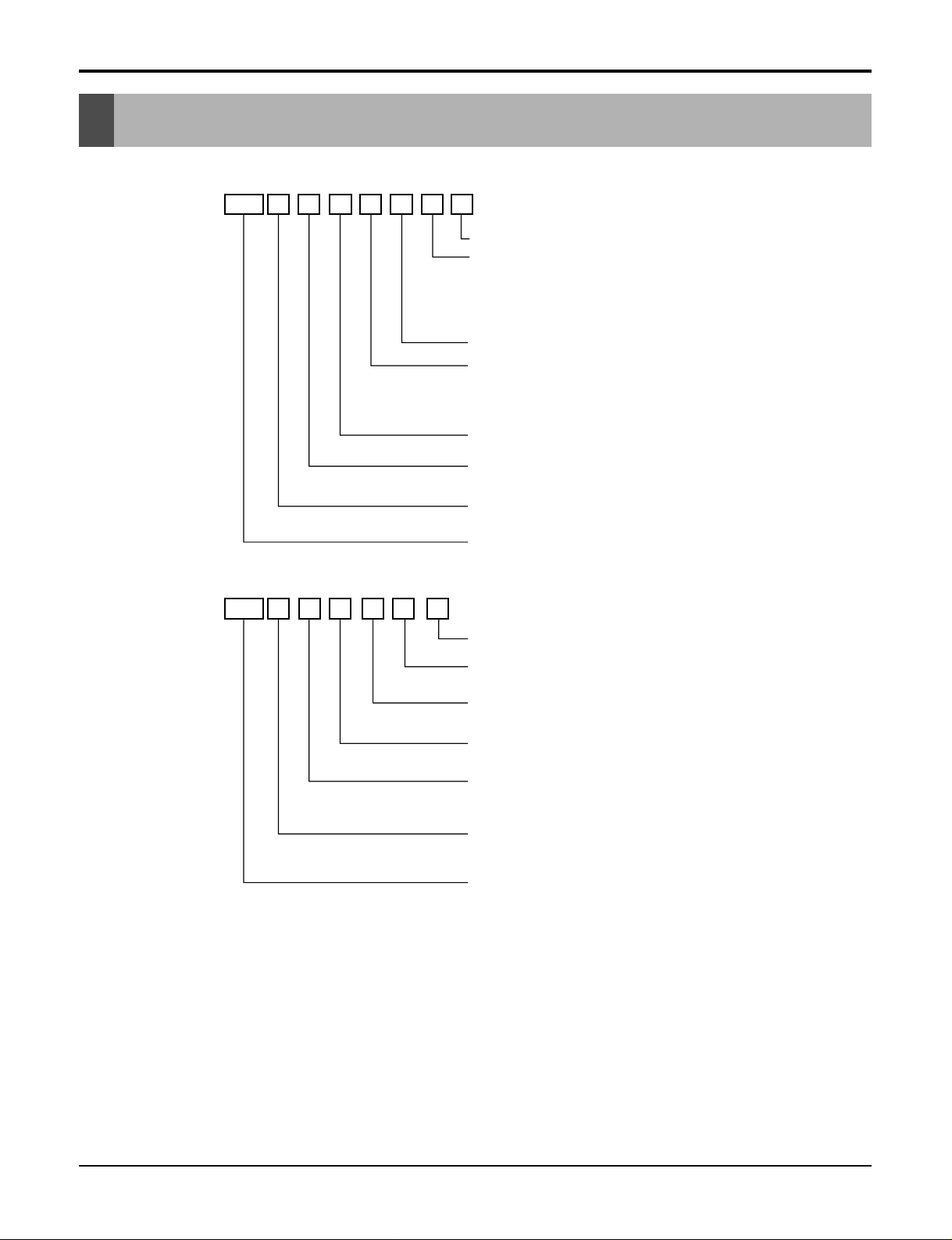
Model Number Nomenclature
Model Number Nomenclature
Indoor Unit
Outdoor Unit
AMN H 6
07
QLA0
Serial Number
A2U W 618 F A 0
Electrical Ratings
TPS Inverter Multi System Indoor Unit
Model Type
H : Heat Pump
Ex) 7,000 Btu/h '07', 18,000 Btu/h '18'
Nominal Cooling Capacity in Btu/h
Electrical Rating
6 : 1Ø, 220-240V, 50Hz
Chassis Name
Indoor Unit Type
L : Wall Mounted , A : ART COOL
D : ART COOL DELUXE, T : Ceiling Cassette
B : Ceiling Concealed Duct
V : Ceiling & Floor(Convertible)
Function
A : Basic, L : Nano Plasma + Auto Clean(Wall Mounted)
C: Plasma(Ceiling Cassette), G: Low Static Motor
ART COOL(DELUXE) Type Front Panel Color
B : Blue, D : Wood, M : Meta, R : Mirror, W : White
R410A
TPS Inverter Multi
System Outdoor Unit.
And No. of Connectable Indoor Units
Ex) A2U : Connectable max. 2 Indoor Units
A6U : Connectable max. 6 Indoor Units
Model Type
W : DC Inverter Heat Pump
Ex) 18,000 Btu/h '18', 48,000 Btu/h, '48'
Nominal Cooling Capacity in Btu/h
6 : 1Ø, 220-240V, 50Hz
8 : 3Ø, 380-415V, 50Hz
Multi Type
Function
A : Basic
F : Free Joint Multi Type
Serial Number
Page 4
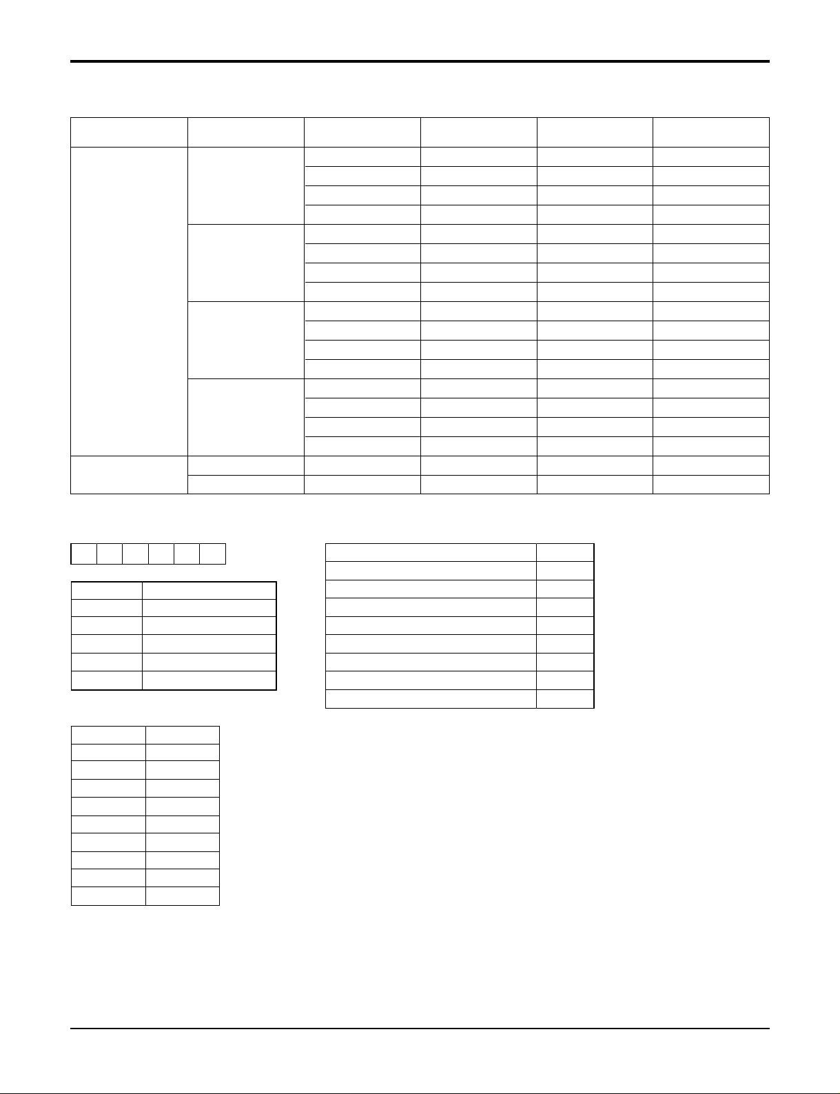
Model Number Nomenclature
Panel (Cassette, Built in Duct)
4 Multi type Air Conditioner
PT-CFA 3721A10072B 8435002992862 COOLING
TF
PT-CFC 3721A10072G 8435002992879 COOLING + PLASMA
PT-HFA 3821A10072A 8435002992886 HEATING
PT-HFC 3721A10072E 8435002992893 HEATING + PLASMA
PT-CCA 3721A10023Z 8435002994095 COOLING
TC
PT-CCC 3721A10023W 8435002994101 COOLING + PLASMA
PT-HCA 3721A10023Y 8435002994118 HEATING
CST PANEL
PT-HCC 3721A10023V 8435002994125 HEATING + PLASMA
PT-HEA 3721A10105A 8435002992978 HEATING
TE(family look)
PT-HEC 3721A10105B 8435002992985 HEATING + PLASMA
PT-CEA 3721A10105C 8435002992954 COOLING
PT-CEC 3721A10105D 8435002992961 COOLING + PLASMA
PT-HAD 3721A10106A 8435002994057 HEATING
TD(family look)
PT-HDC 3721A10106B 8435002994064 HEATING + PLASMA
PT-CDA 3721A10106C 8435002994071 COOLING
PT-CDC 3721A10106D 8435002994088 COOLING + PLASMA
BUILT IN DUCT
BP PB-HPA 3721A20168A 9K/12K
BQ PB-HQA 3721A20168B 18K/24K
Category CHASSIS PANEL NAME PANEL P/NO. SERIAL NO. Remark
123456
PT-HEA
Basic A
B
Plasma Filter C
D
Elevation Grille E
Elevation Grille + Plasma Filter F
TE/TB/TD Before 2003 : Basic 0
TE/TD Before 2003 : Plasma Filter 1
6. Function
5. Chassis Name
Function
Number Contents
1, 2 Panel for Cassette
34 Cooling/Heatpump
5 Chassis Name
6 Function
Chassis Abbrevation
TC C
TB B
TD D
TE E
TF F
TH H
TJ J
BP P
BQ Q
Page 5
Service Manual 5
Model Number Nomenclature
Indoor Units
Outdoor Units
2.1
(7000)
2.6
(9000)
3.5
(12000)
5.3
(18000)
7.0
(24000)
8.8
(30000)
10.6
(36000)
SQ
AMNH
076LQL0
AMNH
096LQL0
-- - - -
SR
-
AMNH
096LRL0
AMNH
126LRL0
----
ST
---
AMNH
186LTL0
AMNH
246LTC0
--
General
SP1
-
AMNN
096AP*1
AMNN
126AP*1
----
SZ
AMNH
076DZ*0
--- - - -
SU
-
AMNH
096DU*0
AMNH
126DU*0
----
1Way
TC
-
AMNH
096TCC0
AMNH
126TCC0
----
TE
--
AMNH
126TEC0
AMNH
186TEC0
-- -
TF
----
AMNH
246TFC0
AMNH
306TFC0
-
TD
------
AMNH
366TDC0
BH
---
AMNH
186BHA0
AMNH
246BHA0
--
BG
-----
AMNH
306BGA0
AMNH
366BGA0
Low
Static
BT
-
AMNH
096BTG0
AMNH
126BTG0
AMNH
186BTG0
-- -
Built in
BP
-
AMNH
096BPA0
AMNH
126BPA0
----
VE
-
AMNH
096VEA0
AMNH
126VEA0
----
VB
---
AMNH
186VBA0
AMNH
246VBA0
--
Chasiss
Model Name
Capacity, kW(Btu/h)
Wall
Mounted
General
Ceiling &
Floor
Convertible
Category Type
ART
COOL
Mirror
Ceiling
Cassette
4Way
Ceiling
Concealed
Duct
High
Static
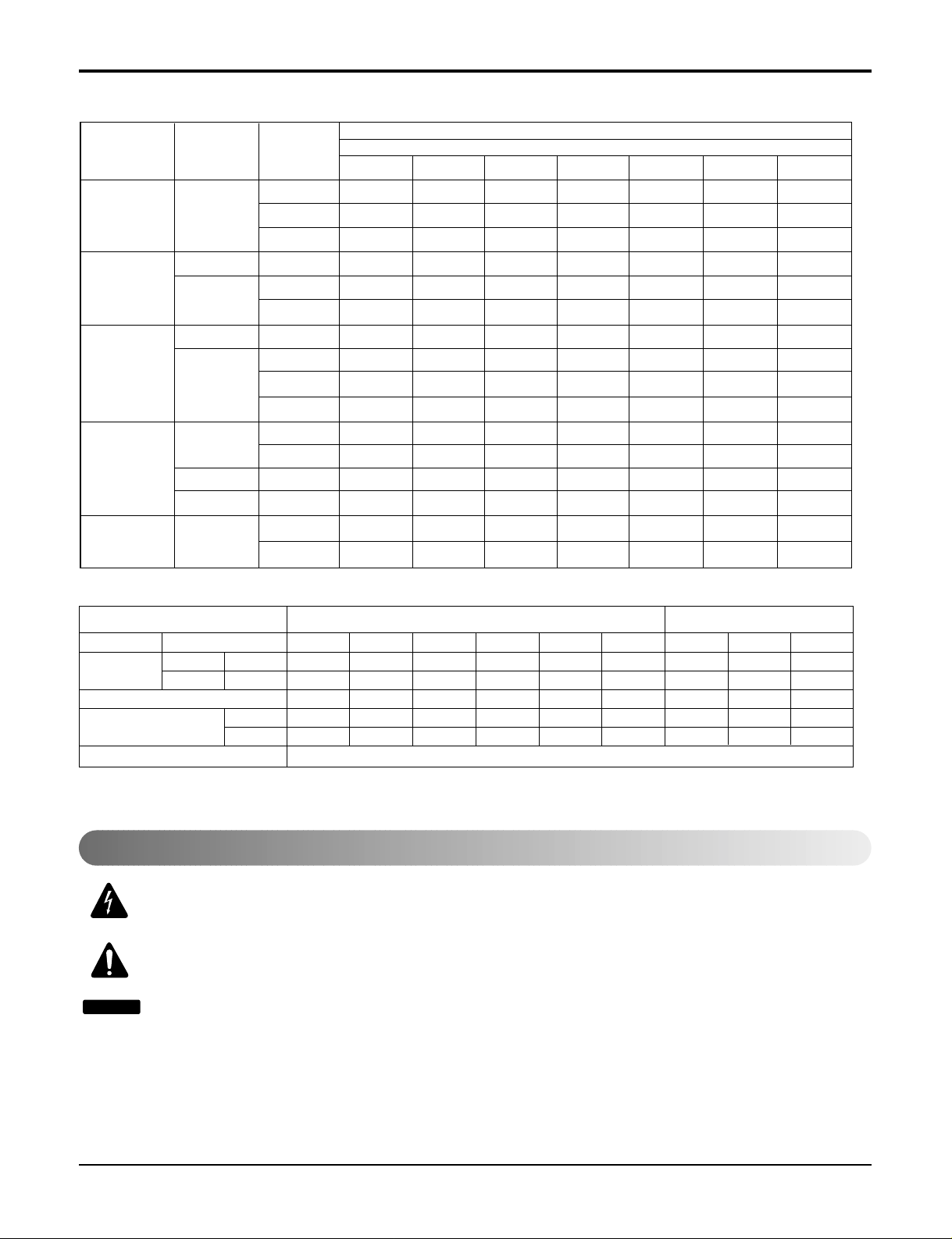
Notes :
A2UW146FA0, A2UW186FA0 and A3UW186FA0 are not TPS inverter system but one inverter compressor system.
TPS Inverter Multi Series Multi Piping Type Distributor Type
Heat Pump Model Name
Rated Capacity Cooling kW(Btu/h)
Heating kW(Btu/h)
Number of Indoor Units to be Connected
Indoor Units kW
Connectable Capacity Btu/h
Power Supply
A2UW146FA0 A2UW186FA0 A3UW186FA0 A3UW246FA0 A4UW246FA0 A4UW306FA0 A6UW406FA0 A7UW486FA0 A8UW566FA0
4.7(1600) 5.3(18000) 5.3(18000) 7.0(24000) 7.0(24000) 8.8(30000) 11.7(40000) 14.0(48000) 16.4(56000)
5.3(1800) 6.3(21600) 6.3(21600) 8.2(28000) 8.2(28000) 10.1(34500) 13.5(46000) 16.2(55200) 18.9(64400)
Max.2 Units Max.2 Units Max.3 Units Max.3 Units Max.4 Units Max.4 Units Max.6 Units Max.7 Units Max.8 Units
2.1~6.2 2.1~7.0 2.1~7.0 2.1~9.7 2.1~9.7 2.1~11.4 4.7~15.2 5.6~18.3 6.6~21.3
7000~21000 7000~24000 7000~24000 7000~33000 7000~33000 7000~39000 16000~52000 19200~62400 22400~72800
1Ø, 220-240V, 50Hz
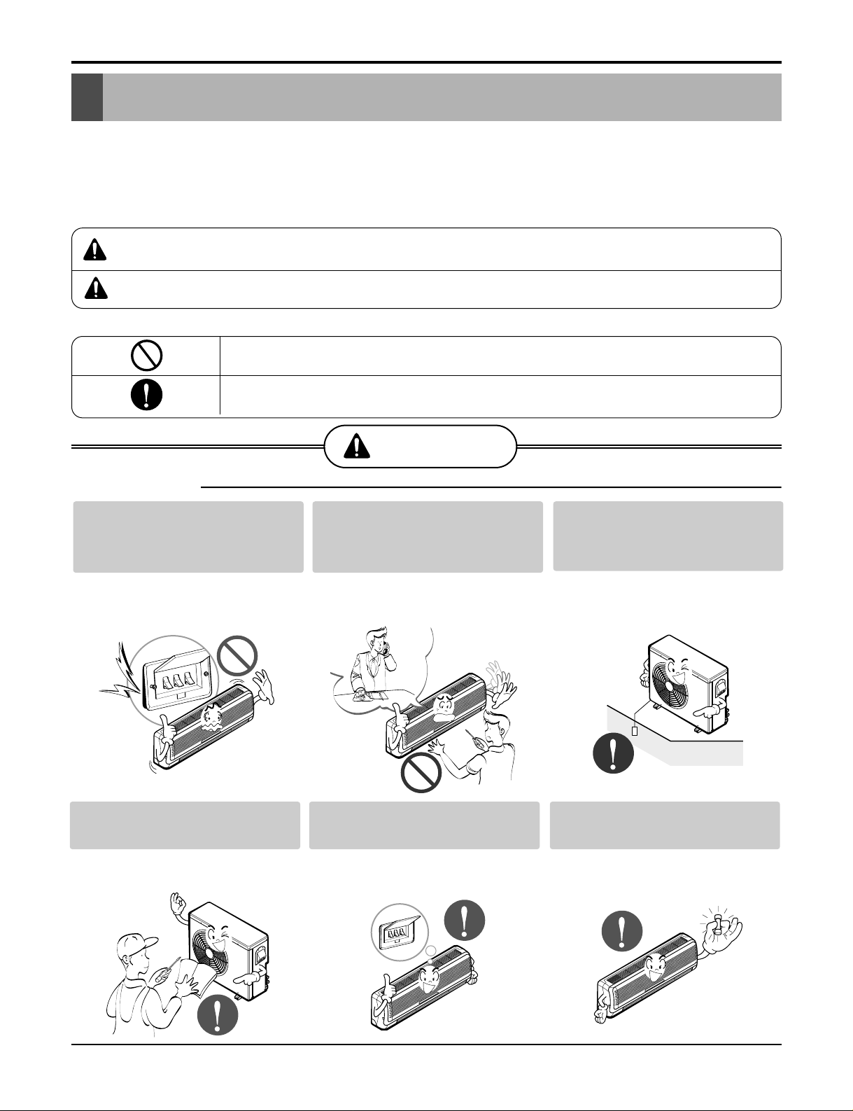
This symbol alerts you to the risk of electric shock.
This symbol alerts you to hazards that could cause harm to the
air conditioner.
This symbol indicates special notes.
NOTICE
Symbols Used in this Manual
Page 6
6 Multi type Air Conditioner
Safety Precautions
Safety Precautions
To prevent injury to the user or other people and property damage, the following instructions must
be followed.
■ Incorrect operation due to ignoring instruction will cause harm or damage. The seriousness is
classified by the following indications.
■ Meanings of symbols used in this manual are as shown below.
This symbol indicates the possibility of death or serious injury.
This symbol indicates the possibility of injury or damage to properties only.
WARNING
■ Installation
Be sure not to do.
Be sure to follow the instruction.
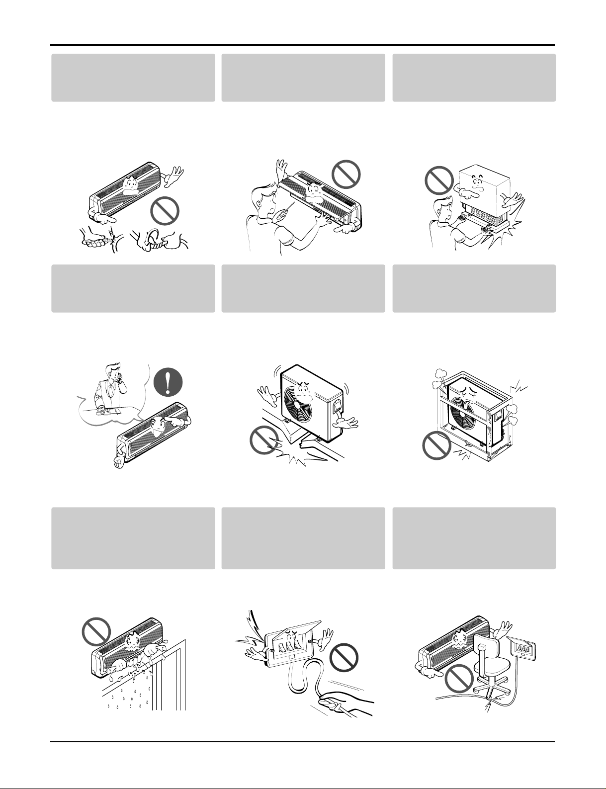
Do not use a defective or underrated circuit breaker. Use this
appliance on a dedicated circuit.
• There is risk of fire or electric
shock.
For electrical work, contact the
dealer, seller, a qualified electrician,
or an Authorized Service Center
.
• Do not disassemble or repair the
product. There is risk of fire or
electric shock.
Always ground the product.
• There is risk of fire or electric
shock.
Install the panel and the cover
of control box securely.
• There is risk of fire or electric
shock.
Always install a dedicated circuit and breaker.
• Improper wiring or installation may
cause fire or electric shock
Use the correctly rated breaker or fuse.
• There is risk of fire or electric
shock.
WARNING
CAUTION
Page 7
Service Manual 7
Safety Precautions
Do not modify or extend the
power cable.
• There is risk of fire or electric
shock.
Do not install, remove, or reinstall the unit by yourself
(customer).
• There is risk of fire, electric shock,
explosion, or injury.
Be cautious when unpacking
and installing the product.
• Sharp edges could cause injury.
Be especially careful of the case
edges and the fins on the condenser and evaporator.
For installation, always contact the dealer or an
Authorized Service Center.
• There is risk of fire, electric shock,
explosion, or injury.
Do not install the product on a
defective installation stand.
• It may cause injury, accident, or
damage to the product.
Be sure the installation area
does not deteriorate with age.
• If the base collapses, the air conditioner could fall with it, causing
property damage, product failure,
and personal injury.
Do not let the air conditioner
run for a long time when the
humidity is very high and a
door or a window is left open.
• Moisture may condense and wet or
damage furniture.
Take care to ensure that
power cable could not be
pulled out or damaged during
operation.
• There is risk of fire or electric
shock.
Do not place anything on the
power cable.
• There is risk of fire or electric
shock.
Page 8
8 Multi type Air Conditioner
Safety Precautions
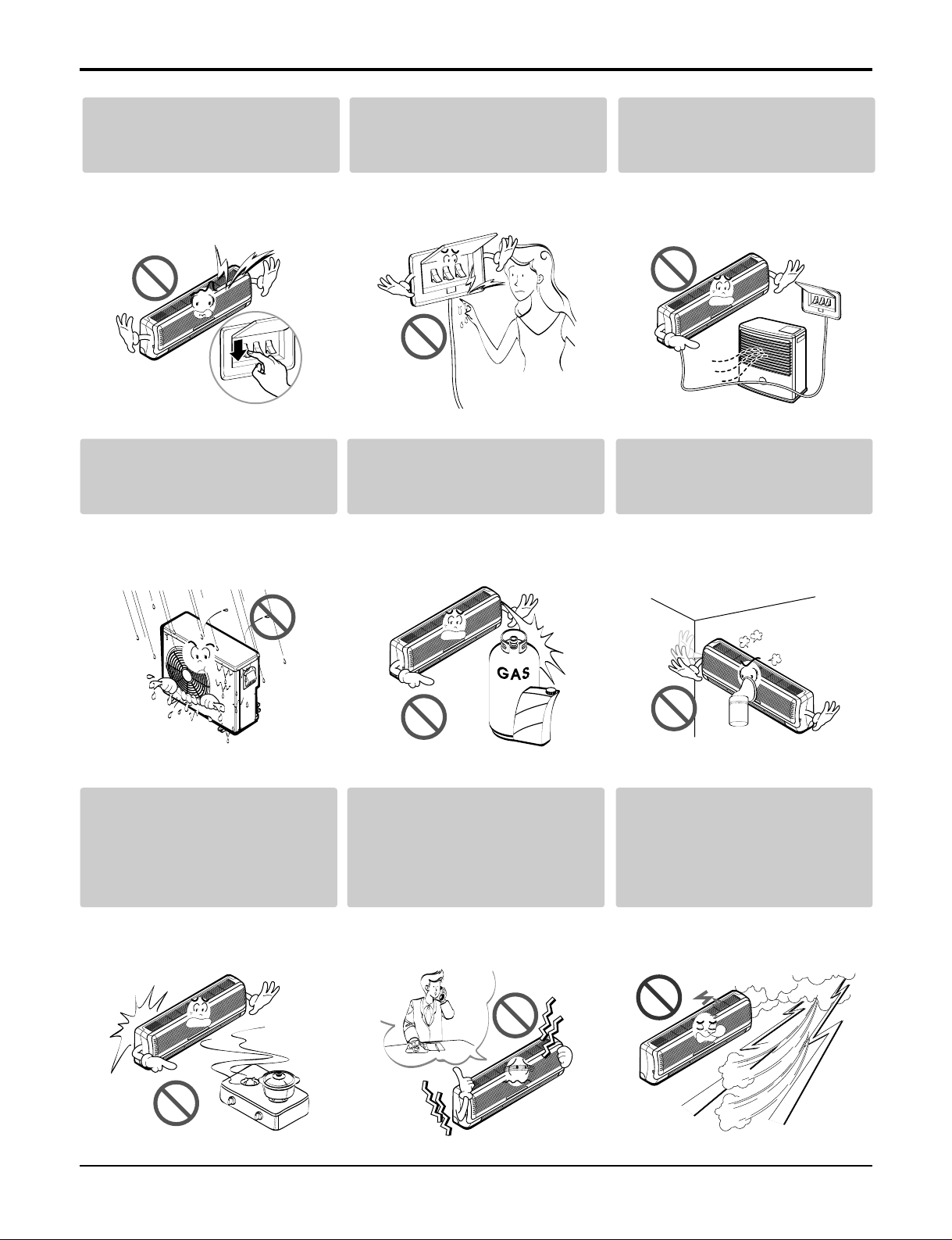
Do not allow water to run into
electric parts.
• It may cause There is risk of fire,
failure of the product, or electric
shock.
Do not store or use flammable
gas or combustibles near the
product.
• There is risk of fire or failure of
product.
Do not use the product in a
tightly closed space for a long
time.
• Oxygen deficiency could occur.
When flammable gas leaks,
turn off the gas and open a
window for ventilation before
turn the product on.
• Do not use the telephone or turn
switches on or off. There is risk of
explosion or fire
If strange sounds, or small or
smoke comes from product.
Turn the breaker off or disconnect the power supply cable.
• There is risk of electric shock or
fire.
Stop operation and close the
window in storm or hurricane.
If possible, remove the product from the window before
the hurricane arrives.
• There is risk of property damage,
failure of product, or electric shock.
Do not plug or unplug the
power supply plug during
operation.
• There is risk of fire or electric
shock.
Do not touch(operate) the
product with wet hands.
• There is risk of fire or electrical
shock.
Do not place a heater or other
appliances near the power
cable.
• There is risk of fire and electric
shock.
Gasolin
Page 9
Service Manual 9
Safety Precautions
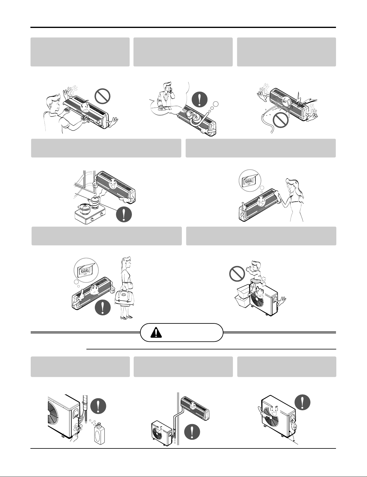
Do not open the inlet grill of the product
during operation. (Do not touch the electrostatic filter, if the unit is so equipped.)
• There is risk of physical injury,
electric shock, or product failure.
When the product is soaked
(flooded or submerged), contact
an Authorized Service Center.
• There is risk of fire or electric
shock.
Be cautious that water could
not enter the product.
• There is risk of fire, electric shock,
or product damage.
Ventilate the product from time to time when
operating it together with a stove, etc.
• There is risk of fire or electric shock.
Turn the main power off when cleaning or
maintaining the product.
• There is risk of electric shock.
When the product is not be used for a long time, disconnect the power supply plug or turn off the breaker.
• There is risk of product damage or failure, or unintended operation.
Take care to ensure that nobody could step on
or fall onto the outdoor unit.
• This could result in personal injury and product damage.
Always check for gas (refrigerant) leakage after installation or repair of product.
• Low refrigerant levels may cause
failure of product.
Install the drain hose to ensure that
water is drained away properly.
• A bad connection may cause water
leakage.
Keep level even when
installing the product.
• To avoid vibration or water leakage.
CAUTION
■ Installation
90°
Page 10
10 Multi type Air Conditioner
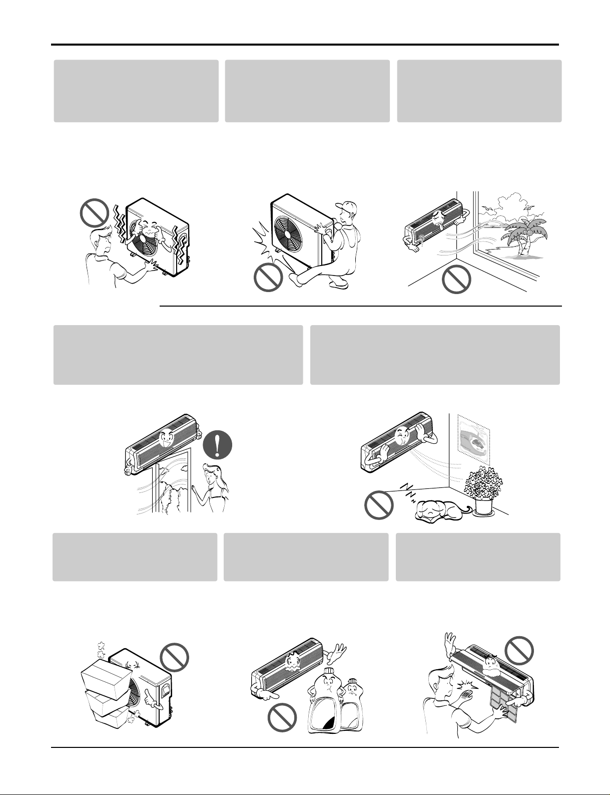
Do not block the inlet or outlet
of air flow.
• It may cause product failure.
Use a soft cloth to clean. Do
not use harsh detergents, solvents, etc.
• There is risk of fire, electric shock,
or damage to the plastic parts of
the product.
Do not touch the metal parts of
the product when removing the
air filter. They are very sharp!
• There is risk of personal injury.
Safety Precautions
Do not install the product
where the noise or hot air
from the outdoor unit could
damage the neighborhoods.
• It may cause a problem for your
neighbors.
Use two or more people to lift
and transport the product.
• Avoid personal injury.
Do not install the product
where it will be exposed to
sea wind (salt spray) directly.
• It may cause corrosion on the
product. Corrosion, particularly on
the condenser and evaporator fins,
could cause product malfunction or
inefficient operation.
Do not expose the skin directly to cool air for
long periods of time.
(Don't sit in the draft.)
• This could harm to your health.
Do not use the product for special purposes,
such as preserving foods, works of art, etc. It
is a consumer air conditioner, not a precision
refrigeration system.
• There is risk of damage or loss of property.
■ Operational
Wax
Thinner
Page 11
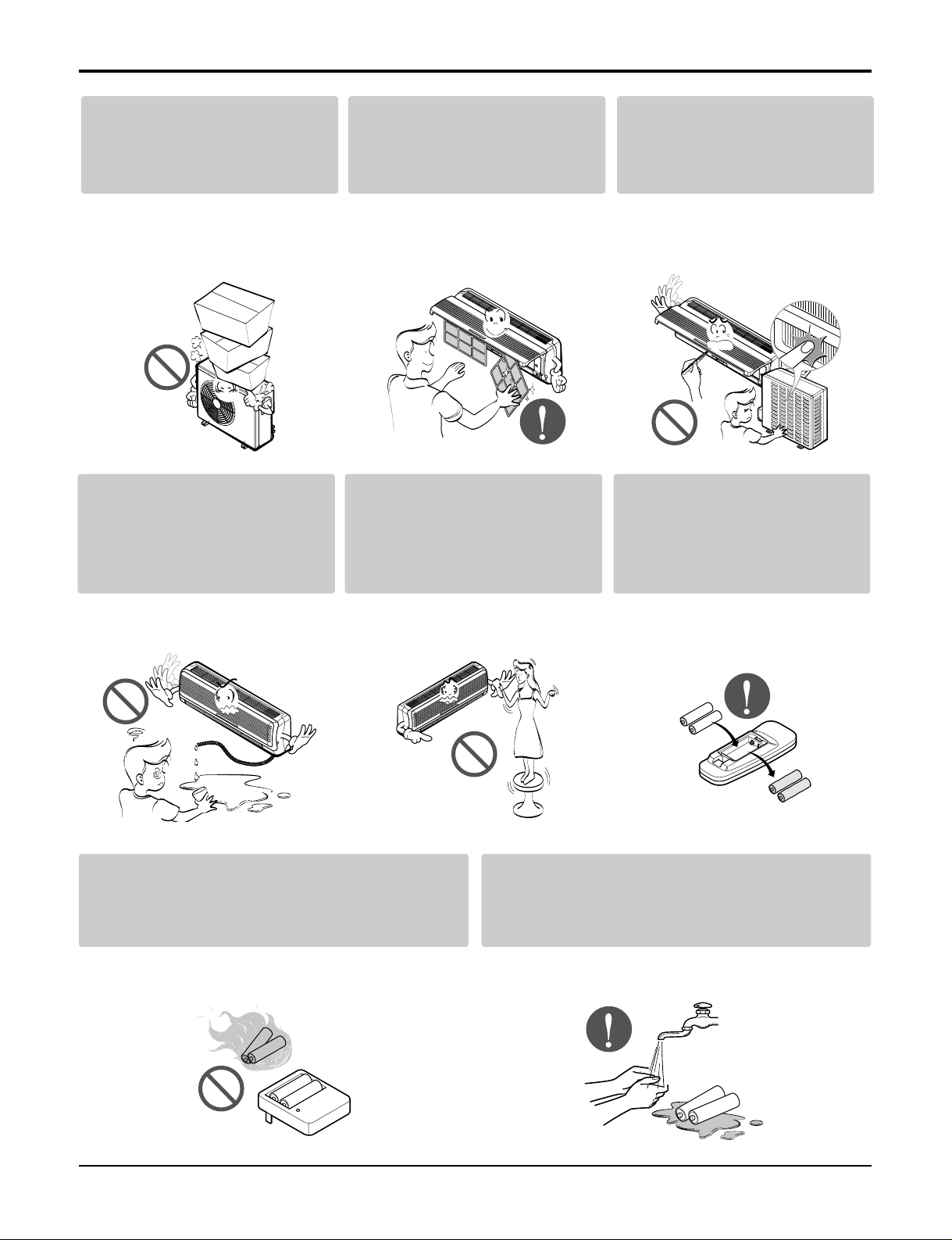
Service Manual 11
Do not step on or put anyting
on the product. (outdoor
units)
• There is risk of personal injury and
failure of product.
Always insert the filter securely. Clean the filter every two
weeks or more often if necessary.
• A dirty filter reduces the efficiency
of the air conditioner and could
cause product malfunction or damage.
Do not insert hands or other
objects through the air inlet or
outlet while the product is
operated.
• There are sharp and moving parts
that could cause personal injury.
Do not drink the water drained
from the product.
• It is not sanitary and could cause
serious health issues.
Use a firm stool or ladder
when cleaning or maintaining
the product.
• Be careful and avoid personal
injury.
Replace the all batteries in the
remote control with new ones
of the same type. Do not mix
old and new batteries or different types of batteries.
• There is risk of fire or explosion
Do not recharge or disassemble the batteries.
Do not dispose of batteries in a fire.
• They may burn or explode.
If the liquid from the batteries gets onto your
skin or clothes, wash it well with clean water.
Do not use the remote if the batteries have
leaked.
• The chemicals in batteries could cause burns or other
health hazards.
Safety Precautions
Page 12
12 Multi type Air Conditioner
Dimensions
Dimensions
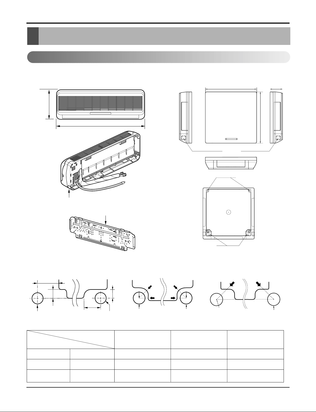
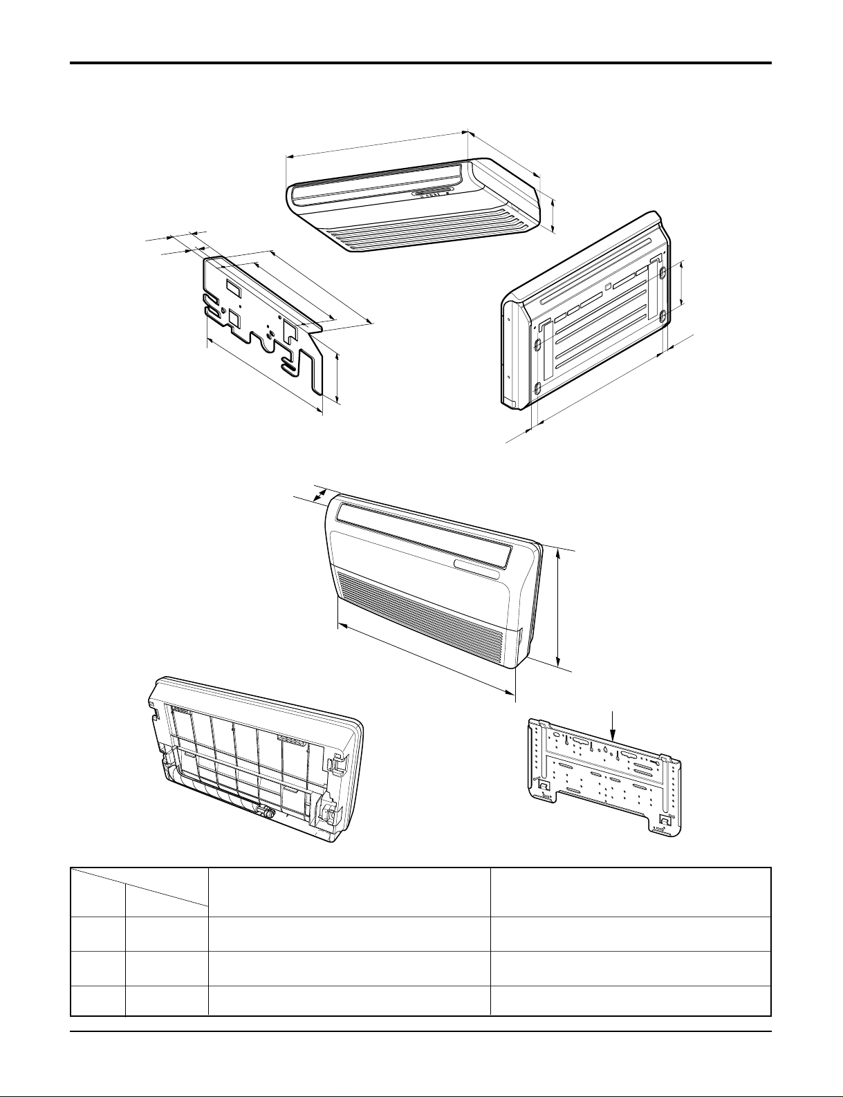
Indoor Unit
1. Split Type Indoor 2. Art Cool Type Indoor Unit
Installation plate
Right rear piping
Left rear piping
ø70mm
ø70mm
50mm
20mm
20mm
80mm
A
A
ø70mm
Center
Center
ø70mm
Left rear piping
Right rear piping
A
A
H
W
Tubing hole cover
Left rear piping Right rear piping
Hole Center
ø70mm
"D"
"C"
(7K, 9K) (9K, 12K) (18K, 24K)
Pipe Hole
Fix Hole
Hanger Hole
H
W
D
W mm 824 900 1,080
H mm 260 285 314
D mm 155 156 172
SQ
7K,9K
SR
9K, 12K
ST
18K, 24K
MODEL
DIM
Page 13
Service Manual 13
Dimensions
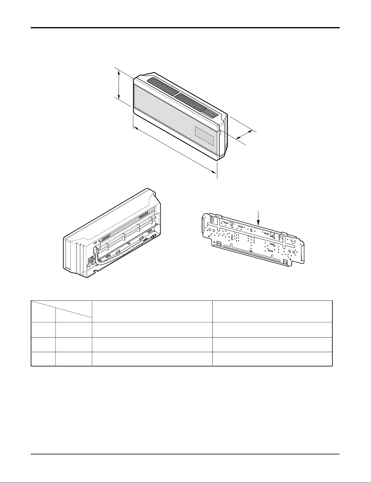
Installation plate
D
H
W
MODEL
DIM Unit
W mm 900 1030
H mm 272 290
D mm 135 153
SZ
7K
SU
9K, 12K
3. Art Cool Deluxe Type
Page 14
14 Multi type Air Conditioner
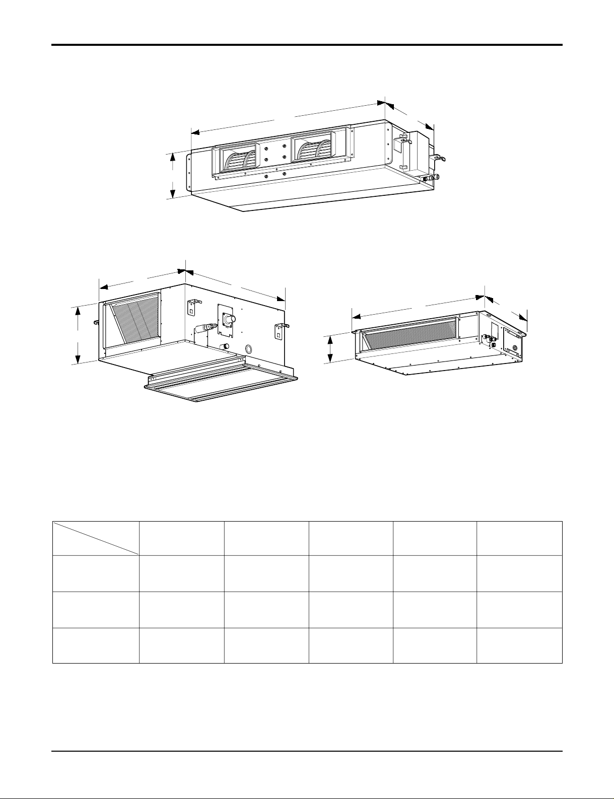
Dimensions
W
H
D
H
H
D
BH/BG
BP BT/BT1
W
W
D
MODEL
DIM
W(mm) 708 1060 880 1180 580
H(mm) 230 230 260 298 300
D(mm) 537 357 450 450 750
BT
9K/12K
BT1
18K
BH
18K/24K
BG
30K/36K
BP
9K/12K
4. Duct Type
Page 15
Service Manual 15
Dimensions
5. CVT Type
VE(9K/12K)
VB(18K/24K)
R
Installation plate
D
W
H
250mm
36mm
36mm
1076mm
(Rear Side)
63mm
38mm
175mm
(Installation Plate)
392m
m
265m
m
468mm
D
W
H
MODEL
DIM Unit
W mm 900 1200
H mm 285 615
D mm 156 205
VE
9K/12K
VB
18K/24K
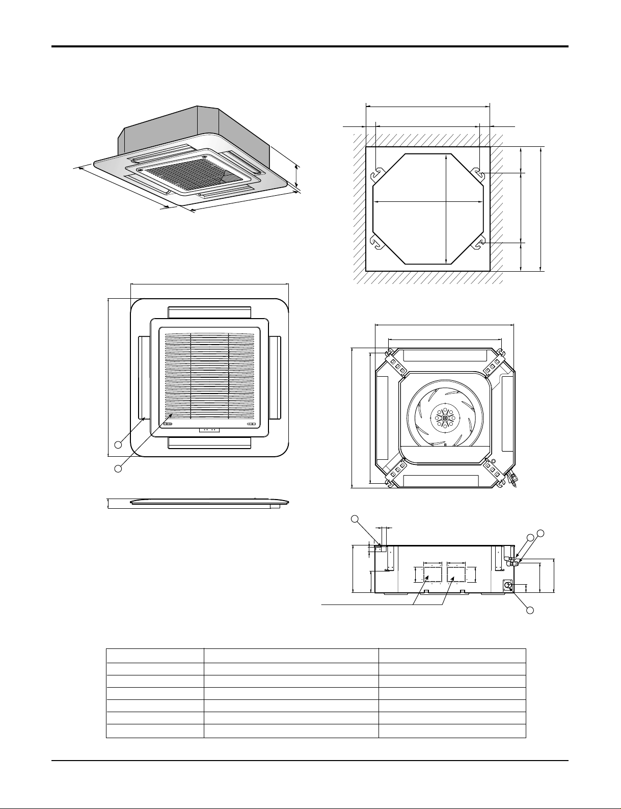
Page 16
16 Multi type Air Conditioner
Dimensions
694.5
1050
480
846
860
328.430.8
390
893.4
931.6
16.7
50
42.7
7
155
97.7
37
116.3
141.8
180
164
194.4
91.6
180
430
130
Ø80
Ø55
180
91.6
1,000 (Ceiling opening)
931.6
893.4 (Hanging bolt)
328.4 (Hanging bolt)
860
390
30.8
430 (Ceiling opening)
4
5
6
3
2
1
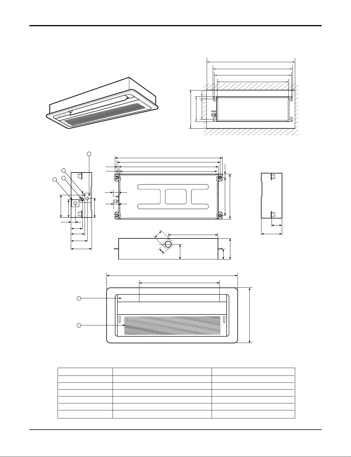
6. CST Type - TC (9K/12K)6. CST Type - TC (9K/12K)
(unit : mm)
Number Name Descripition
1 Liquid pipe connection ø6.35 flare
2 Gas pipe connection ø9.52 flare
3 Drain pipe connection
4 Power supply connection
5 Air discharge grill
6 Air suction grill
Page 17
Service Manual 17
CLOSE OPEN OPEN CLOSE
269
670
30
570
269
190.5
160
52
90
90
120.4
30
521
670
570
450
40
110 110
670
670
4
132
5
6
Unit:mm
570 Unit size
570 Unit size
450 (Hanging bolt)
7575
600 (Ceiling opening)
600 (Ceiling opening)
521(Hanging bolt)
39.5
39.5
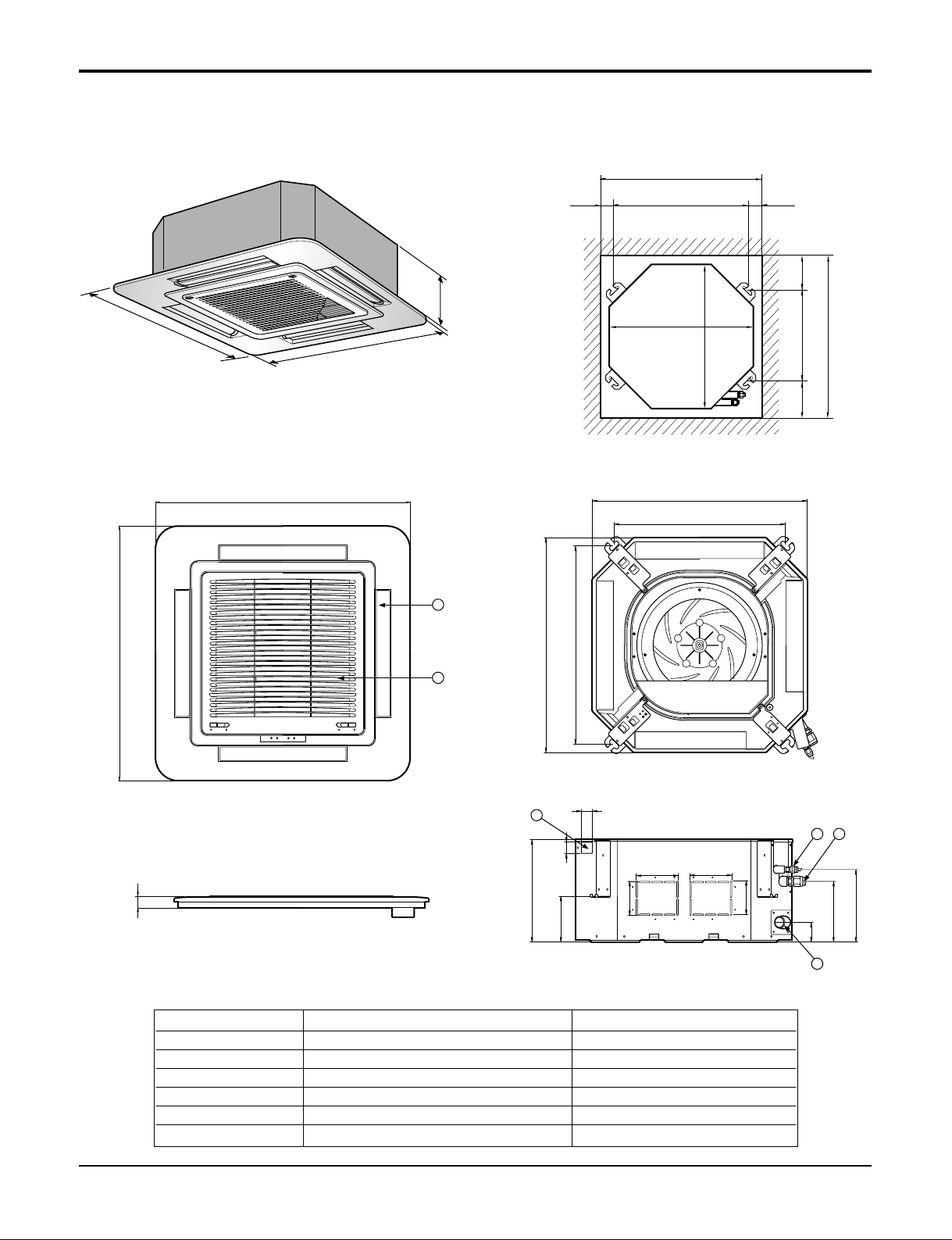
7. CST Type - TE (12K/18K)
Dimensions
(unit : mm)
Number Name Descripition
1 Liquid pipe connection ø6.35 flare
2 Gas pipe connection
12k: ø9.52, 18k: ø12.7 flare
3 Drain pipe connection
4 Power supply connection
5 Air discharge grill
6 Air suction grill
Page 18
18 Multi type Air Conditioner
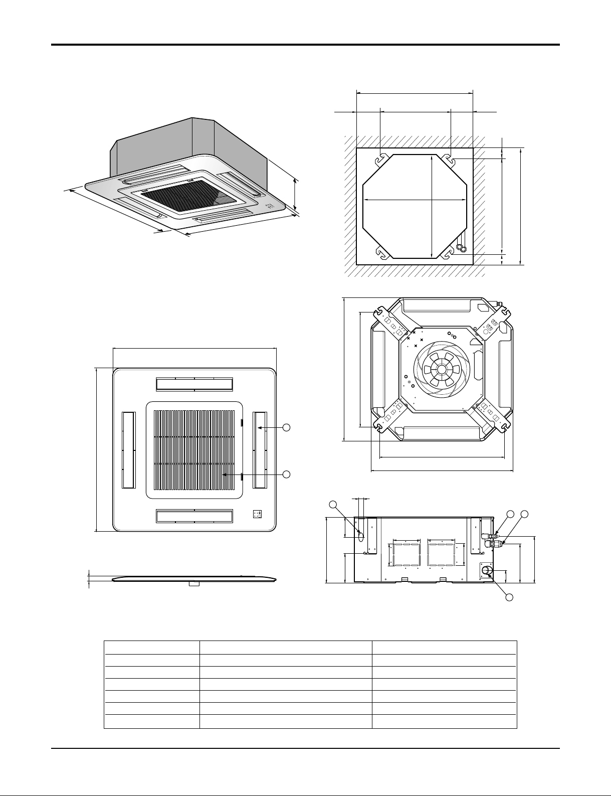
8. CST Type - TF (24K/30K)
292
850
850
850
850
744
658
572
744
292
212
150
54
90
90
192 117
70
110 110
4
132
5
6
Unit:mm
744 Unit size
744 Unit size
658 (Hanging bolt)
6666
790 (Ceiling opening)
790 (Ceiling opening)
572(Hanging bolt)
109
109
30
(unit : mm)
Number Name Descripition
1 Liquid pipe connection ø6.35 flare
2 Gas pipe connection
ø12.7 flare-24K, ø15.88 flare-30K
3 Drain pipe connection
4 Power supply connection
5 Air discharge grill
6 Air suction grill
Dimensions
Page 19
Service Manual 19
9. CST Type - TD(36K)
288
950
950
950
950
290
210.5
180
52
140
40
110
30
90
90
110
55
840
785
840
678
Fresh Air Inlet
Unit:mm
840 Unit size
840 Unit size
672 (Hanging bolt)
101.5101.5
875 (Ceiling opening)
875 (Ceiling opening)
785 (Hanging bolt)
45
45
4
5
6
1
3
2
Dimensions
(unit : mm)
Number Name Descripition
1 Liquid pipe connection ø6.35 flare
2 Gas pipe connection ø15.88 flare
3 Drain pipe connection
4 Power supply connection
5 Air discharge grill
6 Air suction grill
Page 20
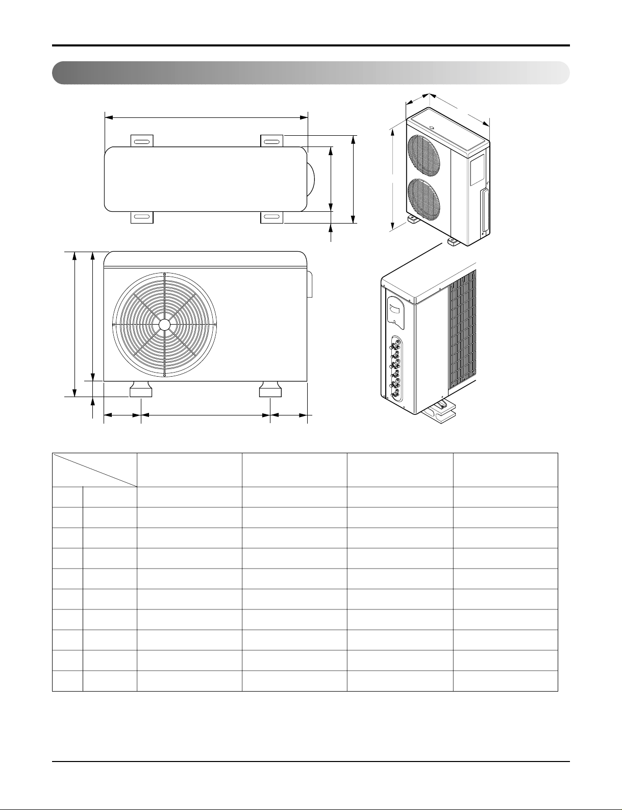
20 Multi type Air Conditioner
Outdoor Unit
W
D
L1
L2
L4
L3
H
L7L5L6
D
W
H
W mm 870 870 870 900
H mm 655 800 1060 1165
D mm 320 320 320 370
L1 mm 370 370 360 460
L2 mm 25 25 20 45
L3 mm 775 775 1040 1135
L4 mm 25 25 20 30
L5 mm 546 546 550 550
L6 mm 160 160 160 175
L7 mm 160 160 165 175
18K 24K 30K 40K
MODEL
DIM
30K/40K
18K/24K
Dimensions
Page 21
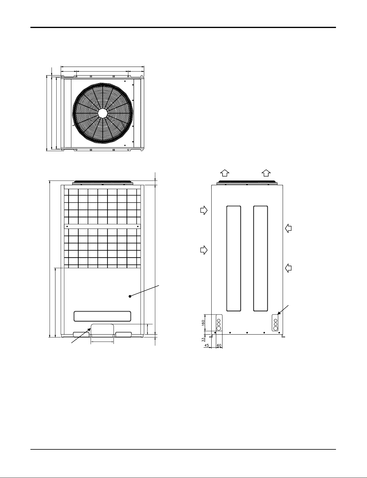
Service Manual 21
Dimensions
A7UW486FA0/A8UW566FA0
806
15
730
690
700(bolt hole)
153
500(bolt hole)
153
1512
670
220
Knockout hole
(For the control wiring, the power supply,
refrigerant connecting pipe)
40
144428
Service Panel
100
Air outlet
Air
inlet
Air
inlet
Knockout hole
(For the control wiring,
the power supply,
refrigerant connecting
pipe)
(Unit : mm)
Page 22
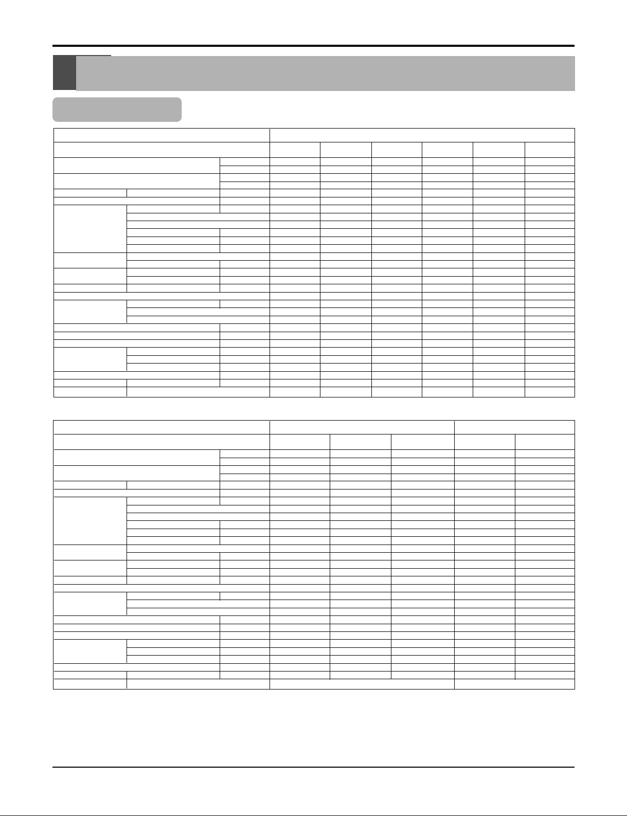
22 Multi type Air Conditioner
Product Specifications
Product Specifications
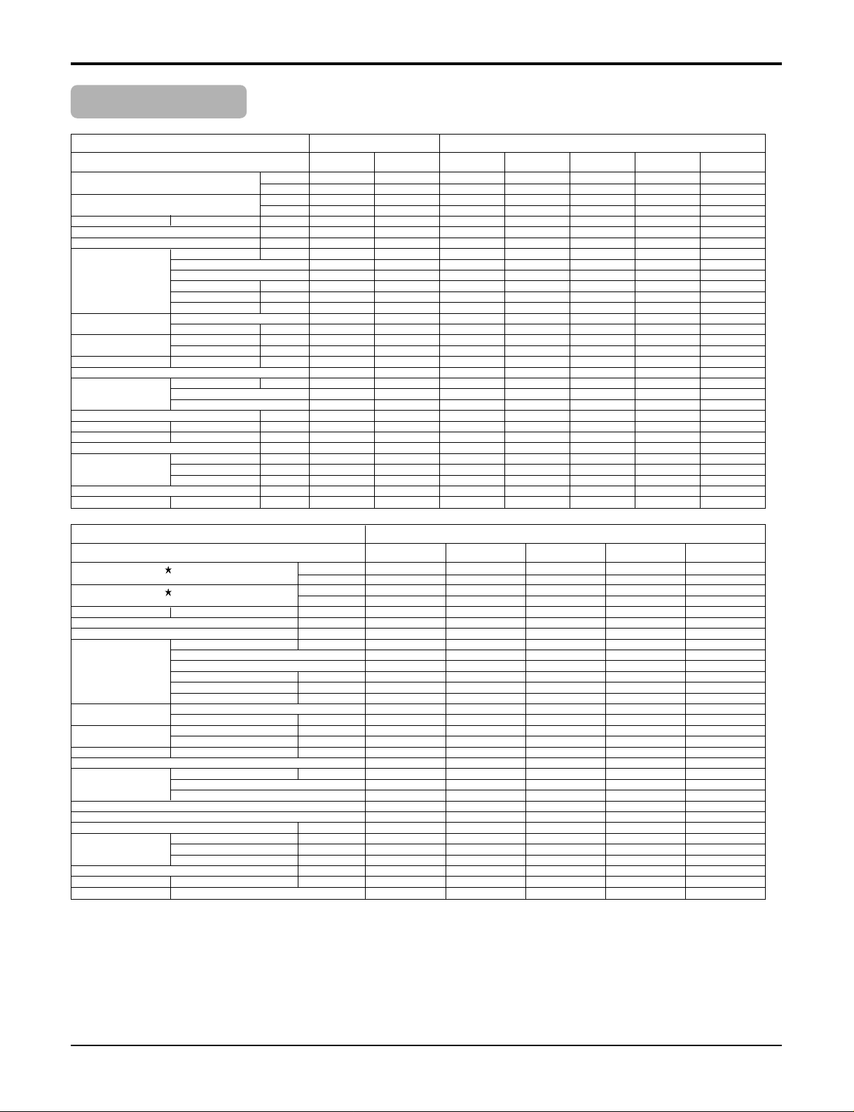
Indoor Unit
Rated Cooling Capacity ★ kcal/hr(W)
Btu/hr
Rated Heating Capacity ★ kcal/hr(W)
Btu/hr
Air Circulation H/M/L
CMM(CFM)
Setting temperature range °C
Fan motor Output W
Model
No. of Poles
Input W
Running Current A
Capacitor µF/Vac
Fan Type
No. Used / Diameter EA/inch(mm)
Fan RPM Cooling(H/M/L) rpm
Heating(H/M/L) rpm
Noise Level
(Sound Press,1m)
H/M/L dBA
Temperature controller
Coil Tube Size (OD) inch(mm)
Fins per inch
No. of Rows & Column
Dehumidification Rate l/h
Dimensions (W*H*D) inch(mm)
Net Weight kg(lbs)
Piping Liquid inch(mm)
Connection Gas inch(mm)
Drain hose (ID Ø)mm
Packing Dimension (W*H*D) inch(mm)
Stuffing Quantity
Without S/Parts 20/40ft
Front Panel Color "★" Position
Wall Mounted
AMNH076LQL0 AMNH096LQL0 AMNH096LRL0 AMNH126LRL0 AMNH186LTL0 AMNH246LTL0
Indoor Unit Type
Model
1764(2051) 2267(2638) 2267(2638) 3024(3515) 4536(5275) 5544(6446)
7000 9000 9000 12000 18000 22000
2016(2343) 2520(2929) 2520(2929) 3326(3867) 4990(5803) 6099(7091)
8000 10000 10000 13200 19800 24200
5.5(194) 8.5(300) 8.5(300) 9.0(318) 13(459) 14(494)
18~30 / 16~30 18~30 / 16~30 18~30 / 16~30 18~30 / 16~30 18~30 / 16~30 18~30 / 16~30
8.4 8.4 14.4 14.4 22 29
IC-8415LG62A IC-8415LG62A IC-8420LG48A IC-8420LG48A AMR-023E2 AMR-023E5
44 44 46
25 25 37 37 54 59
0.11 0.11 0.16 0.16 0.21 0.21
0.9 / 400 0.9 / 400 0.9 / 400 0.9 / 400 2.0 / 370 2.0 / 370
Cross Flow Fan Cross Flow Fan Cross Flow Fan Cross Flow Fan Cross Flow Fan Cross Flow Fan
1/3.43(87) 1/3.43(87) 1/3.43(87) 1/3.43(87) 1/3.74(95) 1/3.74(95)
1080 / 970 / 880 1170 / 1100 / 1020 1200/1100/1000 1290 / 1200 / 1120 1140 / 1040 / 940 1260 / 1140 / 1000
1080 / 970 / 880 1170 / 1100 / 1020 1200/1100/1000 1290 / 1200 / 1120 1140 / 1040 / 940 1260 / 1140 / 1000
35 / 32 / 29 37 / 33 / 31 35 / 33 / 31 39 / 36 / 34 42 / 39 / 36 46 / 43 / 39
Thermistor Thermistor Thermistor Thermistor Thermistor Thermistor
0.197(5.0) 0.197(5.0) 0.197(5.0) 0.197(5.0) 0.276(7.0) 0.276(7.0)
19 19 20 20 20 20
2R,10C 2R,10C 2R,12C 2R,12C 2R,13C 2R,13C
1.0 1.2 1.4 1.8 2.0 2.5
32.4*10.2*6.1(824*260*155) 32.4*10.2*6.1(824*260*155) 35.4*11.2*6.1(900*285*156) 35.4*11.2*6.1(900*285*156) 42.9*12.4*6.8(1090*314*172) 42.9*12.4*6.8(1090*314*172)
7(15.4) 7(15.4) 8(17.6) 8(17.6) 12(26.5) 12(26.5)
1/4 (6.35) 1/4 (6.35) 1/4 (6.35) 1/4 (6.35) 1/4 (6.35) 1/4 (6.35)
3/8 (9.52) 3/8 (9.52) 3/8 (9.52) 3/8 (9.52) 1/2 (12.7) 1/2 (12.7)
20 20 20 20 20 20
35.4*9.2*13.4(900*233*340) 35.4*9.2*13.4(900*233*340) 38.4*9.2*14.6(976*233*372) 38.4*9.2*14.6(976*233*372) 45.9*10.0*15.3(1165*255*388) 45.9*10.0*15.3(1165*255*388)
354/774 (360/780) 354/774 (360/780) 338/714 (340/720) 338/714 (340/720) 264/536 (270/540) 264/536 (270/540)
Morning Beige Morning Beige Morning Beige Morning Beige Morning Beige Morning Beige
Rated Cooling Capacity ★ kcal/hr(W)
Btu/hr
Rated Heating Capacity ★ kcal/hr(W)
Btu/hr
Air Circulation H/M/L
CMM(CFM)
Setting temperature range °C
Fan motor Output W
Model
No. of Poles
Input W
Running Current A
Capacitor µF/Vac
Fan Type
No. Used / Diameter EA/inch(mm)
Fan RPM Cooling(H/M/L) rpm
Heating(H/M/L) rpm
Noise Level
(Sound Press,1m)
H/M/L dBA
Temperature controller
Coil Tube Size (OD) inch(mm)
Fins per inch
No. of Rows & Column
Dehumidification Rate l/h
Dimensions (W*H*D) inch(mm)
Net Weight kg(lbs)
Piping Liquid inch(mm)
Connection Gas inch(mm)
Drain hose (ID Ø)mm
Packing Dimension (W*H*D) inch(mm)
Stuffing Quantity
Without S/Parts 20/40ft
Front Panel Color "★" Position
ART COOL DELUXE ART COOL
AMNH076DZ*0 AMNH096DU*0 AMNH126DU*0 AMNH096AP*1 AMNH126AP*1
Indoor Unit Type
Model
1764(2051) 2267(2638) 2772(3224) 2267(2638) 2772(3224)
7000 9000 12000 9000 12000
1940(2257) 2495(2901) 3049(3546) 2520(2929) 3049(3546)
8000 10000 13200 10000 13200
5.5(194) 8.5(300) 9.0(318) 7.5(264) 8.5(300)
18~30 / 16~30 18~30 / 16~30 18~30 / 16~30 18~30 / 16~30 18~30 / 16~30
4.7 7.8 7.8 24 24
OBM-1547P2 OBM-1547P2 OBM-1547P2 SIC-39CV-D828-1 SIC-39CV-D828-1
444 88
27 40 40 18 18
0.12 0.18 0.18 0.08 0.08
0.9/400 0.9/400 0.9/400 - -
Cross Flow Fan Cross Flow Fan Cross Flow Fan Turbo Fan Turbo Fan
1/3.43(87) 1/3.43(87) 1/3.43(87) 1/24.32(617.7) 1/24.32(617.7)
1330/1230/1130 1320/1220/1120 1400/1300/1200 510/350/290 560/460/360
1330/1230/1130 1320/1220/1120 1400/1300/1200 510/350/290 560/460/360
35 / 32 / 29 37 / 33 / 31 39 / 36 / 34 38 / 35 /32 43 / 40 / 33
Thermistor Thermistor Thermistor Thermistor Thermistor
0.197(5.0) 0.197(5.0) 0.197(5.0) 0.197(5.0) 0.197(5.0)
19 19 19 20 20
2R,12C 2R,12C 2R,12C 2R,20C 2R,20C
1.0 1.2 1.5 1 1.2
42.9*12.4*6.8(1090*314*172) 35.4*10.7*5.3(900*272*135) 40.6*11.4*6.0(1030*290*153) 22.4*22.4*5.4 (570*568*137) 22.4*22.4*5.4 (570*568*137)
8.1(17.9) 9.5(20.9) 9.5(20.9) 9(19.84) 9(19.84)
1/4 (6.35) 1/4 (6.35) 1/4 (6.35) 1/4 (6.35) 1/4 (6.35)
3/8(9.52) 3/8(9.52) 3/8(9.52) 3/8 (9.52) 3/8(9.52)
20 20 20 20 20
38.8*8.7*14.3(985*220*363) 44.0*8.9*14.8(1117*225*377) 44.0*8.9*14.8(1117*225*377) 25.7*25.2*8.5(653*641*216) 25.7*25.2*8.5(653*641*216)
340/720 324/684 324/684 239/539 239/539
R:Mirror, M:Metal, N:Walnut, W:White, B:Blue, C:Cherry M:Metal, B:Blue, D:Wood
Note : 1.★See the page "Combination Table"
2. Due to our policy of innovation some specifications may be changed without notification.
Page 23
Service Manual 23
Product Specifications
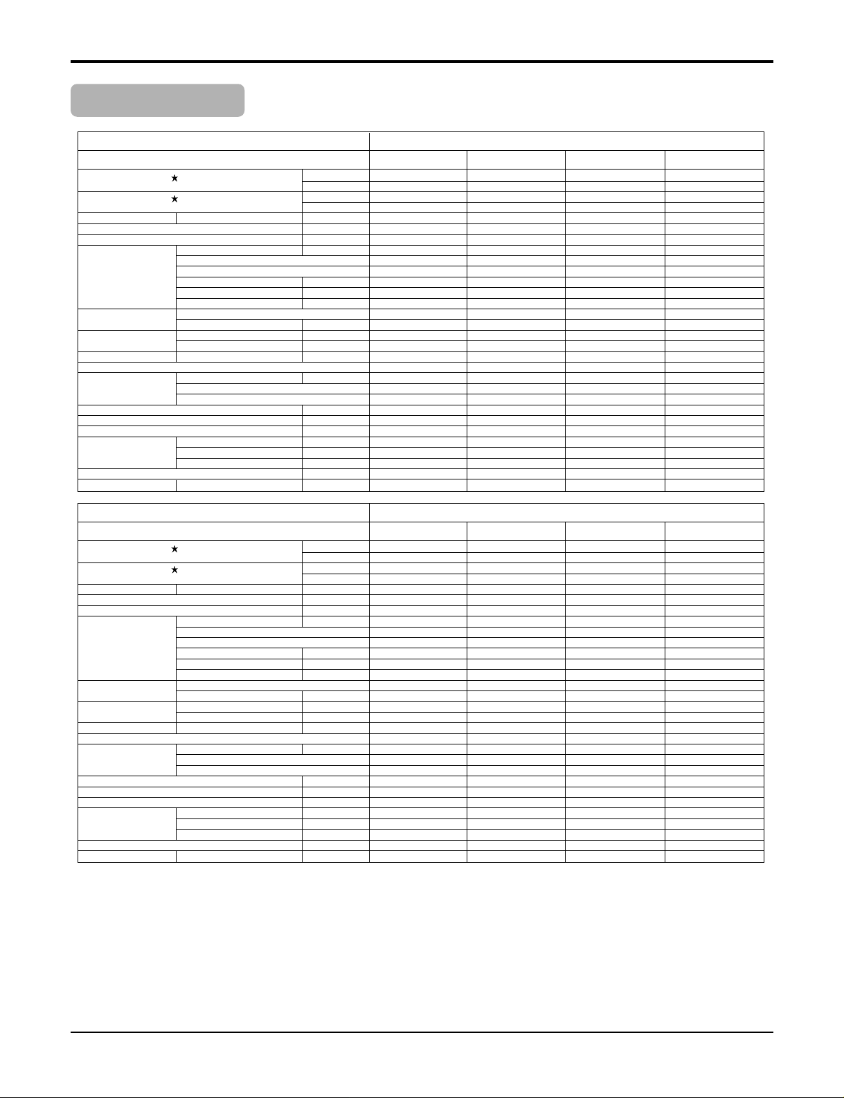
Indoor Unit
2267(2638) 3024(3515) 3024(3515) 4536(5275) 6048(7033) 7056(8206) 9072(10551)
9000 12000 12000 18000 24000 28000 36000
2520(2929) 3326(3867) 3326(3867) 4990(5803) 6653(7736) 7761(9027) 9979(11600)
10000 13200 13200 19800 26400 30800 39600
9(317) 10(353) 11(353) 13(459)
15/14/13(53/494/459)
18(636)
25/23/21(883/812/742)
-------
18~30 / 16~30 18~30 / 16~30 18~30 / 16~30 18~30 / 16~30 18~30 / 16~30 18~30 / 16~30 18~30 / 16~30
14 14 18.4 22.4 40.3 45 52.5
AMR-023E7 AMR-023E7 IC-9630LGAE IC-9630LGAC OBM-350292 OBM-401592 IC-1630LGPJ
4466666
50 50 75 90 121 146 175
0.56 0.56 0.35 0.75 0.53 0.67 0.8
0.9/400 0.9/400 2.5/440 2.5/440 4/440 4/440 4/450
Cross Flow Fan Cross Flow Fan Turbo Fan Turbo Fan Turbo Fan Turbo Fan Turbo Fan
1/4(102) 1/4(102) 1/13.0(330) 1/13.0(330) 1/15.0(382) 1/15.0(382) 1/15.0(382)
900 / 800 / 700 1000 / 900 / 800 670 / 620 / 550 720 / 670 / 620 600/540480 660/590/530 550/510/470
900 / 800 / 700 1000 / 900 / 800 670 / 620 / 550 720 / 670 / 620 600/540480 660/590/530 550/510/470
35 /32 / 28 37 / 33 / 29 38 / 35 / 32 41 /39 / 37 43/41/39 44/41/39 40/38/36
Thermistor Thermistor Thermistor Thermistor Thermistor Thermistor Thermistor
0.275(7) 0.275(7) 0.275(7) 0.275(7) 0.275(7) 0.275(7) 0.275(7)
18 18 19 19 21 21 21
2R11C 2R11C 2R11C 2R11C 2R12C 2R12C 2R12C
1.2 1.5 1.2 2.4 3 3.5 4
33.8*15.3*7(860*390*190) 33.8*15.3*7(860*390*190) 22.4*10.5*22.4 (570*269*570) 22.4*10.5*22.4 (570*269*570) 29.3*11.5*29.4 (744*292*744) 29.3*11.5*29.4 (744*292*744) 33.0*33.0*11.3(840*840*288)
41.3*18.9*1.2(1050*480*30) 41.3*18.9*1.2(1050*480*30) 26.4*26.4*1.2(670*670*30) 26.4*26.4*1.2(670*670*30) 33.5*33.5*1.2(850*850*30) 33.5*33.5*1.2(850*850*30) 37.4*37.4*1.2(950*950*30)
22(48.5) 22(48.5) 19(41.9) 19(41.9) 24(52.9) 24(52.9) 32(70.5)
1/4 (6.35) 1/4 (6.35) 1/4 (6.35) 1/4 (6.35) 1/4 (6.35) 1/4 (6.35) 1/4 (6.35)
3/8(9.52) 3/8(9.52) 3/8(9.52) 1/2 (12.7) 1/2 (12.7) 1/2 (12.7) 1/2 (12.7)
32 32 32 32 32 32 32
38.6*10.0*18.1 38.6*10.0*18.1(980*255*460) 25.2*13.0*25.2(640*330*640) 25.2*13.0*25.2(640*330*640) 32.6*14.4*32.6 (828*365*828) 32.6*14.4*32.6 (828*365*828) 36.4*13.8*36.4(925*350*925)
263/539 263/539 189/378 189/378 84/168 84/168 30/64(36/72)
Rated Cooling Capacity ★ kcal/hr(W)
Btu/hr
Rated Heating Capacity ★ kcal/hr(W)
Btu/hr
Air Circulation H/M/L
CMM(CFM)
External Static Pressure mmAq
Setting temperature range °C
Fan motor Output W
Model
No. of Poles
Input W
Running Current A
Capacitor µF/Vac
Fan Type
No. Used / Diameter EA/inch(mm)
Fan RPM Cooling(H/M/L) rpm
Heating(H/M/L) rpm
Noise Level
(Sound Press,1m)
H/M/L dBA
Temperature controller
Coil Tube Size (OD) inch(mm)
Fins per inch
No. of Rows & Column
Dehumidification Rate l/h
Dimensions (W*H*D) Indoor inch(mm)
Panel inch(mm)
Net Weight kg(lbs)
Piping Liquid inch(mm)
Connection Gas inch(mm)
Drain hose (ID Ø)mm
Packing Dimension (W*H*D) inch(mm)
Stuffing Quantity
Without S/Parts 20/40ft
Ceiling Cassette - 1way Ceiling Cassette - 4way
AMNH096TCC0 AMNH126TCC0 AMNH126TEC0 AMNH186TEC0 AMNH246TFC0 AMNH306TFC0 AMNH366TDC0
Indoor Unit Type
Model
Rated Cooling Capacity kcal/hr(W)
Btu/hr
Rated Heating Capacity kcal/hr(W)
Btu/hr
Air Circulation H/M/L
CMM(CFM)
External Static Pressure mmAq
Setting temperature range °C
Fan motor Output W
Model
No. of Poles
Input W
Running Current A
Capacitor µF/Vac
Fan Type
No. Used / Diameter EA/inch(mm)
Fan RPM Cooling(H/M/L) rpm
Heating(H/M/L) rpm
Noise Level
(Sound Press,1m)
H/M/L dBA
Temperature controller
Coil Tube Size (OD) inch(mm)
Fins per inch
No. of Rows & Column
Dehumidification Rate l/h
Dimensions (W*H*D) inch(mm)
Net Weight kg(lbs)
Piping Liquid inch(mm)
Connection Gas inch(mm)
Drain hose (ID Ø)mm
Packing Dimension (W*H*D) inch(mm)
Stuffing Quantity
Without S/Parts 20/40ft
Front Panel Color "*" Position
2268(2637) 3024(3516) 4536(5274) 2268(2637) 3024(3516)
9000 12000 18000 9000 12000
2520(2930) 3326(3868) 4990(5802) 2520(2930) 3326(3868)
10000 13000 19800 10000 13200
8/7/6(282/246/211) 10/9/8(352/317/282) 13.5/12/10(477/424/353) 11.5/10/8.5 11.5/10/8.5
22244
18~30 / 16~30 18~30 / 16~30 18~30 / 16~30 18~30 18~30
35 35 47 118 118
YDK110-35-4L YDK110-35-4L YSK110-70-4L IC-13450LG31A IC-13450LG31A
44444
68 68 126 180 180
0.31 0.31 0.58 4.3 4.3
2.5/400 2.5/400 2.5/370 6/370 6/370
Sirocco Fan Sirocco Fan Sirocco Fan Sirocco Fan Sirocco Fan
1/7.8(197) 1/7.8(197) 2/7.8(197) 1/Ø177 1/Ø177
930/840/810 950/850/780 1000/900/800 1125/990/870 1125/990/870
930/840/810 950/850/780 1000/900/800 1125/900/870 1125/990/870
34/32/30 37/34/31 38/36/34 38/36/34 38/36/34
Thermistor Thermistor Thermistor Thermistor Thermistor
0.276(7.0) 0.276(7.0) 0.276(7.0) 0.276(7.0) 0.276(7.0)
18 18 18 18 18
2R,12C 3R,12C 2R, 12C 2R14C 3R14C
1 1.2 2 1.6 2
25.6*9.0*21.1(650*230*535) 25.6*9.0*21.1(650*230*535) 39.4*9.0*21.1(1000*230*535) 750*300*580(695*56.5*396) 750*300*580(695*56.5*396)
22(48.5) 22(48.5) 29(63.9) 30(6) 30(6)
1/4 (6.35) 1/4 (6.35) 1/4 (6.35) 1/4(6.35) 1/4(6.35)
3/8 (9.52) 3/8 (9.52) 1/2 (12.7) 3/8(9.52) 3/8(9.52)
25.4 25.4 25.4 25.4(OD) 25.4(OD)
29.9*24.6*11.8(760*625*300) 29.9*24.6*11.8(760*625*300) 29.9*24.6*11.8(760*625*300) 845*370*760(735*90*435) 845*370*760(735*90*435)
172/356 172/356 123/251 228/468 228/468
- - - NOBEL WHITE NOBEL WHITE
Ceiling Concealed Duct
AMNH096BTG0 AMNH126BTG0 AMNH186BTG0 AMNH096BPA0 AMNH126BPA0
Indoor Unit Type
Model
Note : 1.★See the page "Combination Table"
2. Due to our policy of innovation some specifications may be changed without notification.
Page 24
24 Multi type Air Conditioner
Product Specifications
Indoor Unit
Rated Cooling Capacity kcal/hr(W)
Btu/hr
Rated Heating Capacity kcal/hr(W)
Btu/hr
Air Circulation H/M/L
CMM(CFM)
External Static Pressure mmAq
Setting temperature range °C
Fan motor Output W
Model
No. of Poles
Input W
Running Current A
Capacitor µF/Vac
Fan Type
No. Used / Diameter EA/inch(mm)
Fan RPM Cooling(H/M/L) rpm
Heating(H/M/L) rpm
Noise Level
(Sound Press,1m)
H/M/L dBA
Temperature controller
Coil Tube Size (OD) inch(mm)
Fins per inch
No. of Rows & Column
Dehumidification Rate l/h
Dimensions (W*H*D) inch(mm)
Net Weight kg(lbs)
Piping Liquid inch(mm)
Connection Gas inch(mm)
Drain hose (ID Ø)mm
Packing Dimension (W*H*D) inch(mm)
Stuffing Quantity
Without S/Parts 20/40ft
Ceiling & Floor(Convertible)
AMNH096VEA0 AMNH126VEA0 AMNH186VBA0 AMNH246VBA0
Indoor Unit Type
Model
2268(2637) 3024(3516) 4536(5274) 6048(7032)
9000 12000 18000 24000
2520(2930) 3326(3867) 4990(5801) 6350(7384)
10000 132000 19800 25200
7.8/6.4/5.0(276/226/177) 10.0/8.3/6.5(353/293/230) 135./12/11(477/424/388) 15/13.5/12(530/477/424)
--- -
18-30/16-30 18-30/16-30 18~30 / 16~30 18~30 / 16~30
14.5 17.5 30 35
IC-18422LG31B IC-18422LG31A IC-9430LGCM IC-9430LGCM
444 4
35 43 53 63
0.18 0.23 0.23 0.27
1.5/370 1.5/370 1.5/370 1.5/370
Cross Flow Fan Cross Flow Fan Cross Flow Fan Cross Flow Fan
1/3.7(95) 1/3.7(95) 1/3.1(80) 1/3.1(80)
960/870/760 1240/1120/900 1090/990/890 1160/1060/960
960/870/760 1240/1120/900 1090/990/890 1160/1060/960
36/32/28 40/36/31 43 / 40 / 37 45 / 42 / 39
Thermistor Thermistor Thermistor Thermistor
0.197(5) 0.197(5) 0.275(7) 0.275(7)
20 20 18 20
2R 12C 2R 12C 2R 12C 2R 14C
1 1.2 2.3 3.2
35.4*7.9*19.3 (900*200*490) 35.4*7.9*19.3 (900*200*490) 47.24*24.21*8.07(1200*615*205) 47.24*24.21*8.07(1200*615*205)
12(26.5) 12(26.5) 30(66.1) 30(66.1)
1/4 (6.35) 1/4 (6.35) 1/4(6.35) 1/4(6.35)
3/8 (9.52) 3/8 (9.52) 1/2(12.7) 1/2(12.7)
20 20 20 20
38.2*11.2*22.2 (970*285*565) 38.2*11.2*22.2 (970*285*565) 50*10.9*27(1272*278*686) 50*10.9*27(1272*278*686)
189/383 189/383 102/219 102/219
Rated Cooling Capacity kcal/hr(W)
Btu/hr
Rated Heating Capacity kcal/hr(W)
Btu/hr
Air Circulation H/M/L
CMM(CFM)
External Static Pressure mmAq
Setting temperature range °C
Fan motor Output W
Model
No. of Poles
Input W
Running Current A
Capacitor µF/Vac
Fan Type
No. Used / Diameter EA/inch(mm)
Fan RPM Cooling(H/M/L) rpm
Heating(H/M/L) rpm
Noise Level
(Sound Press,1m)
H/M/L dBA
Temperature controller
Coil Tube Size (OD) inch(mm)
Fins per inch
No. of Rows & Column
Dehumidification Rate l/h
Dimensions (W*H*D) inch(mm)
Net Weight kg(lbs)
Piping Liquid inch(mm)
Connection Gas inch(mm)
Drain hose (ID Ø)mm
Packing Dimension (W*H*D) inch(mm)
Stuffing Quantity
Without S/Parts 20/40ft
Ceiling Concealed Duct
AMNH186BHA0 AMNH246BHA0 AMNH306BGA0 AMNH366BGA0
Indoor Unit Type
Model
4536(5275) 6048(7034) 7560(8792) 9072(10551)
18000 24000 30000 36000
4990(5803) 6653(7737) 8316(9671) 9979(11606)
19800 26400 33000 39600
16.5/14.5/13(583/512/459) 18/16.5/14(636/583/494) 28/25/23(989/883/812) 32/29/26.5(1130/1024/936)
888 8
18~30 / 16~30 18~30 / 16~30 18~30 / 16~30 18~30 / 16~30
118 118 124 272
IC-13450LG13C IC-13450LG13C IC-13450LG13J IC-13450LG13A
444 4
180 180 250 323
0.92 0.92 1.1 1.42
6/370 6/370 6/370 6/370
Sirocco Fan Sirocco Fan Sirocco Fan Sirocco Fan
2/6.97(177) 2/6.97(177) 2/6.97(177) 2/6.97(177)
1356/-/1270 1417/1350/1255 1415/1360/1290 1415/1360/1290
1356/-/1270 1417/1350/1255 1415/1360/1290 1415/1360/1290
36/34/32 37/35/33 40/38/36 42/40/38
Thermistor Thermistor Thermistor Thermistor
0.275(7) 0.275(7) 0.275(7) 0.275(7)
21 21 21 21
3R10C 3R10C 3R 12C 3R 12C
2.0 2.5 3 3.5
34.6*10.2*17.7 (880*260*450) 34.6*10.2*17.7 (880*260*450) 46.4*11.7*17.7(1180*298*450) 46.4*11.7*17.7(1180*298*450)
35(77.2) 35(77.2) 38(83.8) 38(83.8)
1/4(6.35) 1/4(6.35) 1/4(6.35) 1/4(6.35)
1/2(12.7) 1/2(12.7) 5/8(15.88) 5/8(15.88)
25.4(OD) 25.4(OD) 25.4(OD) 25.4(OD)
44.7*13.4*23.0(1135*340*585) 44.7*13.4*23.0(1135*340*585) 18.5*14.8*23.0(1435*375*585) 18.5*14.8*23.0(1435*375*585)
120/252 120/252 95/191 95/191
Note : 1.★See the page "Combination Table"
2. Due to our policy of innovation some specifications may be changed without notification.
Page 25
Service Manual 25
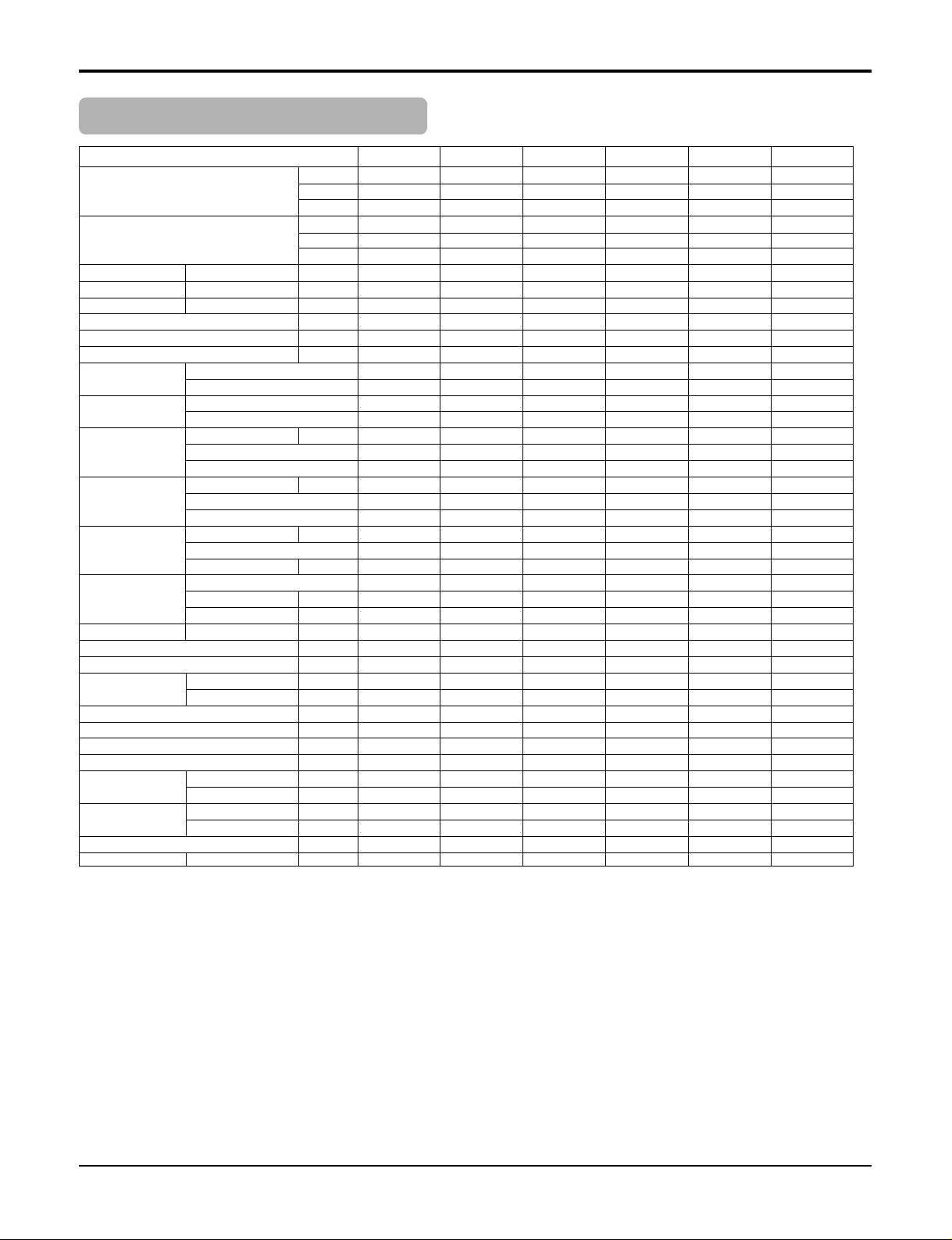
Outdoor Unit - Multiple piping models
Product Specifications
Notes: 1. Capacities are based on the following conditions:
Cooling: - Indoor Temperature 27°C(80.6°F) DB /19°C(66.2°F) WB Heating: - Indoor Temperature 20°C(68°F) DB / 15°C(59°F) WB
- Outdoor Temperature 35°C(95°F) DB /24°C(75.2°F) WB - Outdoor Temperature 7°C(44.6°F) DB / 6°C(42.8°F) WB
- Interconnecting Piping Length 7.5m - Interconnecting Piping Length 7.5 m
- Level Difference of Zero. - Level Difference of Zero.
2. Capacities are Net Capacities.
3.
★
: See the page "Combination Table"
4. Due to our policy of innovation some specifications may be changed without notification.
Model
Cooling Capacity ★ kcal/hr
W
Btu/hr
Heating Capacity ★ kcal/hr
W
Btu/hr
Input ★ Cooling/Heating W
Running Current ★ Cooling/Heating A
Starting Current Cooling/Heating A
Power Supply Ø,V,Hz
Power Factor %
Max. Number of Connectable Indoor Units %
Compressor Type
(Invertor) O.L.P Type(model name)
Compressor Type
(Constant) O.L.P Type(model name)
Refrigerant Charge g(oz), type
Type
Control
Coil Tube Size (OD) inch(mm)
Fins per inch
No. of Rows & Column/No.
Fan Motor Model W
Output
Capacitor µF/Vac
Fan Type
No. Used / Diameter EA/inch(mm)
Discharge Side / Top
Air Circulation CMM(CFM)
Noise Level(Sound Press,1m) dBA
Defrosting
SVC Valve Liquid inch(mm)
Gas inch(mm)
Dimensions (W*H*D) inch(mm)
Net Weight kg(lbs)
Power Supply Cable No.* mm
2
Interunit Cable No.* mm
2
Max. Interunit
Total of Each Room m
Piping Length
For One Room m
Max. Installation Indoor Unit~Outdoor Unit m
Height Difference Indoor Unit~Indoor Unit m
Packing Dimension (W*H*D) inch(mm)
Stuffing Quantity Without S/Parts 20/40ft
1159~4031 1159~5443 1159~5443 1159~7257 1159~7257 1159~9072
1348~4688 1348~6330 1348~6330 1348~8,440 1348~8,440 1348~10549
4600~16000 4600~21600 4600~21600 4600~28800 4600~28800 4600~36000
1210~4535 1210~6249 1210~6249 1210~8063 1210~8063 2116~10332
1407~5274 1407~7268 1407~7268 1407~9376 1407~9376 2461~12014
4800~18000 4800~24800 4800~24800 4800~32000 4800~32000 8,400~41,000
380~1450/450~1350 420~2400/480~2600 420~2400/480~2600 440~2970/560~2950 440~2970/560~2950 450~3580/620~3580
1.6~6.5/2.0~5.8 3.5~11.5/4~12 3.5~11.5/4~12 3.08~13.0/4.6~12.9 3.08~13.0/4.6~12.9 3.2~15.7/4.6~15.7
111282828
1,220~240,50 1,220~240,50 1,220~240,50 1,220~240,50 1,220~240,50 1,220~240,50
94~98 94~98 94~98 94~98 94~98 95~98
223344
e-Scroll e-Scroll e-Scroll e-Scroll e-Scroll e-Scroll
------
- - - Rotary Rotary Rotary
- - - MRA99150-9090 MRA99150-9090 INTERNAL
1650(59.97) at 7.5m 1650(59.97) at 7.5m 1650(59.97) at 7.5m 1950(68.78) at 7.5m 1950(68.78) at 7.5m 2500(88.18) at 7.5m
R-410A R-410A R-410A R-410A R-410A R-410A
L.E.V L.E.V L.E.V L.E.V L.E.V L.E.V
0.276(7.0) 0.276(7.0) 0.276(7.0) 0.276(7.0) 0.276(7.0) 0.276(7.0)
18 18 18 18 18 18
1R,28C 2R,28C 2R,28C 2R,36C 2R,36C 2R,48C
IC28640LG28S IC28640LG28S IC28640LG28S IC28640LG28J IC28640LG28J IC9625LGSY
120 120 120 130 130 65 * 2
6/370 6/370 6/370 6/370 6/370 2.0/370
Propeller Propeller Propeller Propeller Propeller Propeller
1/18.1(460) 1/18.1(460) 1/18.1(460) 1/18.1(460) 1/18.1(460) 2/16.5(420)
Side Discharge Side Discharge Side Discharge Side Discharge Side Discharge Side Discharge
49(1730) 49(1730) 49(1730) 53(1872) 53(1872) 31(1094)*2
50/47 51/48 51/48 51/48 51/48 50/46
Invertion cycle Invertion cycle Invertion cycle Invertion cycle Invertion cycle Invertion cycle
1/4 (6.35)*2EA 1/4 (6.35)*2EA 1/4 (6.35)*3EA 1/4 (6.35)*3EA 1/4 (6.35)*4EA 1/4 (6.35)*4EA
3/8 (9.52)*2EA 3/8 (9.52)*2EA 3/8 (9.52)*3EA 3/8 (9.52)*3EA 3/8 (9.52)*4EA 3/8 (9.52)*4EA
34.3*31.5*12.6 (870*800*320) 34.3*31.5*12.6 (870*800*320) 34.3*31.5*12.6 (870*800*320) 34.3*31.5*12.6 (870*808*320) 34.3*31.5*12.6 (870*808*320) 34.3*31.5*12.6 (870*1038*320)
52(115) 57(125.6) 75(165) 75(165) 75(165) 84(185)
3*3.5 3*3.5 3*3.5 3*2.5 3*2.5 3*2.5
4*0.75 (Includes earth) 4*0.75 (Includes earth) 4*0.75 (Includes earth) 4*0.75 (Includes earth) 4*0.75 (Includes earth) 4*0.75 (Includes earth)
40 40 40 50 50 70
25 25 25 25 25 25
15 15 15 15 15 15
7.5 7.5 7.5 7.5 7.5 7.5
34.2*25.8*12.6(870*655*320) 34.2*25.8*12.6(870*655*320) 34.2*25.8*12.6(870*655*320) 40.1*34.2*17.3 (1020*870*440) 40.1*34.2*17.3 (1020*870*440) 40.1*34.2*17.3 (1045*1140*440)
81/171 81/171 81/171 54/114 54/114 51/111
A2UW146FA0 A2UW186FA0 A3UW186FA0 A3UW246FA0 A4UW246FA0 A4UW306FA0
Page 26
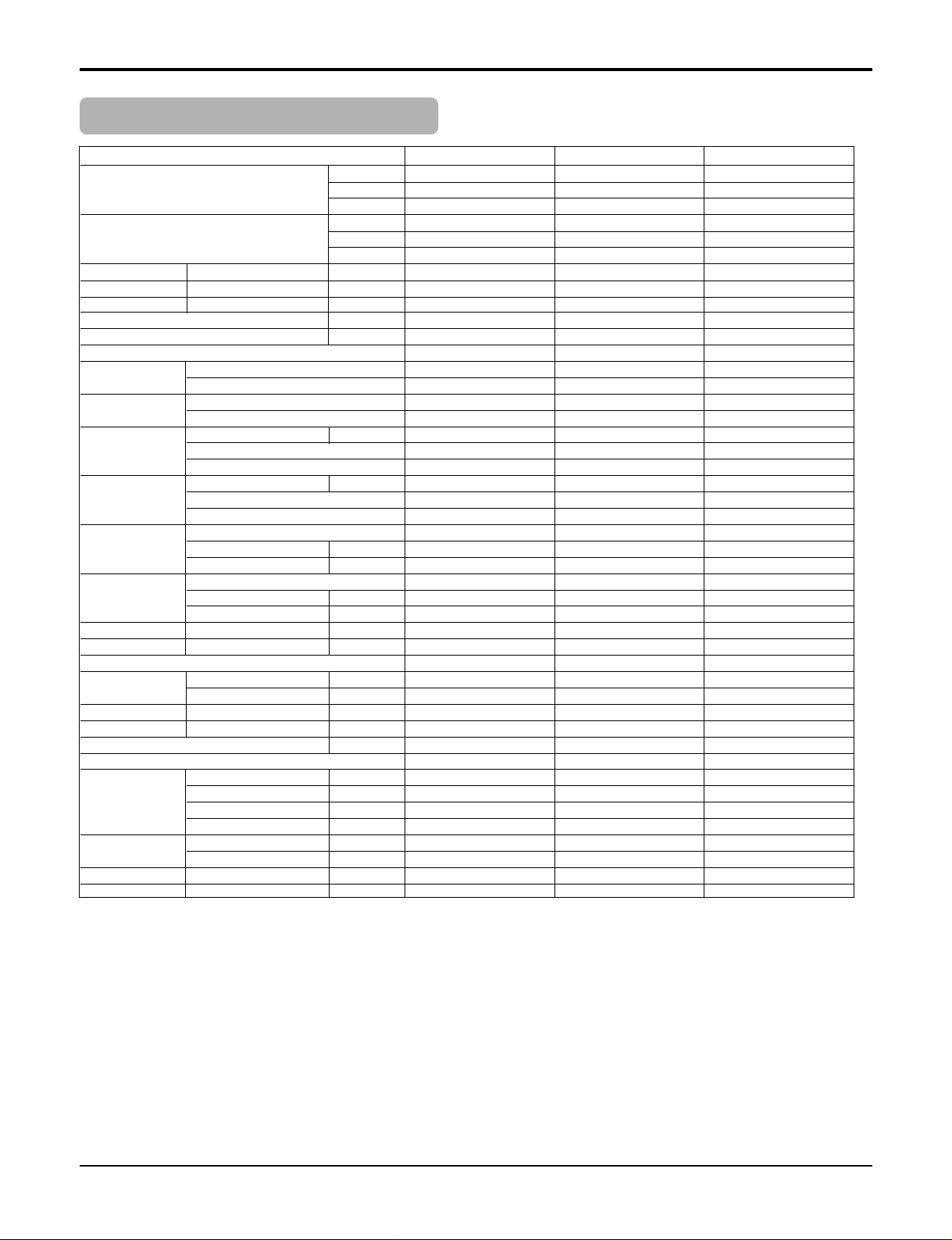
26 Multi type Air Conditioner
Product Specifications
Notes: 1. Capacities are based on the following conditions:
Cooling: - Indoor Temperature 27°C(80.6°F) DB /19°C(66.2°F) WB Heating: - Indoor Temperature 20°C(68°F) DB / 15°C(59°F) WB
- Outdoor Temperature 35°C(95°F) DB /24°C(75.2°F) WB - Outdoor Temperature 7°C(44.6°F) DB / 6°C(42.8°F) WB
- Interconnecting Piping Length 7.5m - Interconnecting Piping Length 7.5 m
- Level Difference of Zero. - Level Difference of Zero.
2. Capacities are Net Capacities.
3.
★
: See the page "Combination Table"
4. Due to our policy of innovation some specifications may be changed without notification.
Model
Cooling Capacity★ kcal/hr
W
Btu/hr
Heating Capacity★ W(kcal/hr)
Btu/hr
Input★ Cooling/Heating W
Running Current★ Cooling/Heating A
Starting Current Cooling/Heating A
Power Supply Ø,V,Hz
Power Factor %
Max. Number of Connectable Indoor Units
Compresso Type
(Invertor) O.L.P Type(model name)
Compressor Type
(Constant) O.L.P Type(model name)
Refrigerant charge Charge g(oz)
Type
Control
Coil Tube Size (OD) inch(mm)
Fins per inch
No. of Rows & Column/No.
Fan motor Model
Output W
Capacitor µF/Vac
Fan Type
No. Used / Diameter EA/inch(mm)
Discharge Side / Top
Air Circulation Outdoor CMM(CFM)
Noise Level Sound Press,1m dB(A)±1
Defrosting
SVC Valve Liquid inch(mm)
Gas inch(mm)
Dimensions W*H*D inch(mm)
Net Weight Outdoor kg(lbs)
Power Supply Cable No.* mm
2
Interunit Cable
Max. Interunit
Total Piping m
Piping Length
Total Main Piping m
Total Branch Piping m
For One Room m
Max. Installation Indoor Unit~Outdoor Unit m
Height Difference Indoor Unit~Indoor Unit m
Packing Dimension W*H*D inch(mm)
Stuffing Quantity With(Without) S/Parts 20/40ft
4032~12095 4032~14515 4032~16934
4689~14067 4689~16878 4689~19691
16,000~48,000 16000~57600 16000~67250
4838~13356 4838~16027 4848~19051
5627~15533 5627~18636 5627~22152
19,200~53,000 19200~63600 19200~75600
1695~4980/2343~4600 750~5810/1450~5830 750~6600/1550~6800
7.9~22/10.5~20.6 3.4~26/6.6~24.3 3.4~29.6/7.1~30.5
67 43 74
1,220~240,50 1,220~240,50 1,220~240,50
87.1~99.4 90~97 90~97
67 8
e-Scroll e-Scroll e-Scroll
Internal Internal Internal
Rotary Rotary Rotary
Internal Internal Internal
4100(144.6) at 5m 7100(250.4) at 5m 7100(250.4) at 5m
R-410A R-410A R-410A
L.E.V L.E.V L.E.V
0.276(7.0) 0.276(7.0) 0.276(7.0)
18 18 18
2R,52C
IC28640LG28J ARE676E01 ARE676E01
120 * 2 270 270
6/370 10/370 10/370
Propeller Propeller Propeller
1/18.1(460) 1/20.7(526) 1/20.7(526)
Side Discharge Top discharge Top discharge
53(1872) *2 90(3179) 90(3179)
60/-/57 59/56 59/56
Invertion cycle Invertion cycle Invertion cycle
3/8 (9.52) 3/8(9.52) 3/8(9.52)
3/4 (19.05) 3/4 (19.05) 3/4 (19.05)
35.4*45.8*14.5 (900*1,165*370) 31.7*59.5*28.7(806*1512*730) 31.7*59.5*28.7(806*1512*730)
110(242) 110(242) 120(264)
3*5.0 3*5.0 3*5.0
4*0.75 (Includes earth) 4*0.75 (Includes earth) 4*0.75 (Includes earth)
100 110 120
50 50 50
50 60 70
15 15 15
30 30 30
10 10 10
40.6*47.7*17.1 (1032*1212*436) 33.9*61.0*28.7(860*1550*730) 33.9*61.0*28.7(860*1550*730)
22/48
A6UW406FA0 A7UW486FA0 A8UW566FA0
Outdoor Unit - Distributor type models
Page 27
Service Manual 27
Model
Connectable Indoor Units
Combination(Min~Max.) Btu/h
Casing color
Powre Source
Power Consumption W
Runing Current A
Refrigerant type
charge kg
Dimensions W*H*D mm
Packing Dimension W*H*D mm
Net Weight kg
Connecting Cable Direction Indoor Unit No. * mm
2
Direction Outdoor Unit No. * mm
2
Piping Connection Liquid inch(mm)
(Main) Gas
Piping Connection Liquid inch(mm)
(Indoor Unit) Gas
Piping length Total m
(Max.) Outdoor ↔ BD m
BD ↔ Indoor m
Piping Elevation Outdoor ↔ Indoor m
(Max.) Indoor ↔ Indoor m
Drain hose
Heat Insulation
Accessories Hanger EA
Screw EA
1~4 1~3 1~2 1~3
7,000~24,000 7,000~24,000 7,000~24,000 7,000~36,000
----
Ø1 , 50/60Hz ,220~240/220V Ø1 , 50/60Hz ,220~240/220V Ø1 , 50/60Hz ,220~240/220V Ø1 , 50/60Hz ,220~240/220V
10 10 10 10
0.05 0.05 0.05 0.05
R410A R410A R410A R410A
---302*143*252 302*143*252 302*143*252 302*143*252
422*202*300 422*202*300 422*202*300 422*202*300
5555
4*0.75 (Includes earth) 4*0.76 (Includes earth) 4*0.77 (Includes earth) 4*0.77 (Includes earth)
4*0.75 (Includes earth) 4*0.76 (Includes earth) 4*0.77 (Includes earth) 4*0.77 (Includes earth)
3/4(19.05) 3/4(19.05) 3/4(19.05) 3/4(19.05)
3/8 (9.52) 3/8 (9.52) 3/8 (9.52) 3/8 (9.52)
1/4 (6.35) 1/4 (6.35) 1/4 (6.35) 1/4 (6.35)
3/8 (9.52) 3/8 (9.52) 3/8 (9.52) 3/8 (9.52)
100 100 100 100
40 40 40 40
20 20 20 20
30 30 30 30
10 10 10 10
Not available
Both Liquid and Gas pipes
4444
8888
PMBD3640 PMBD3630 PMBD3620 PMBD7230
LG Branch Distributor
Product Specifications
Page 28
28 Multi type Air Conditioner
Installation
Installation
Read completely, then follow step by step.
Select the best location of indoor unit
Front
Right Rear right
Rear left
Down right
Left
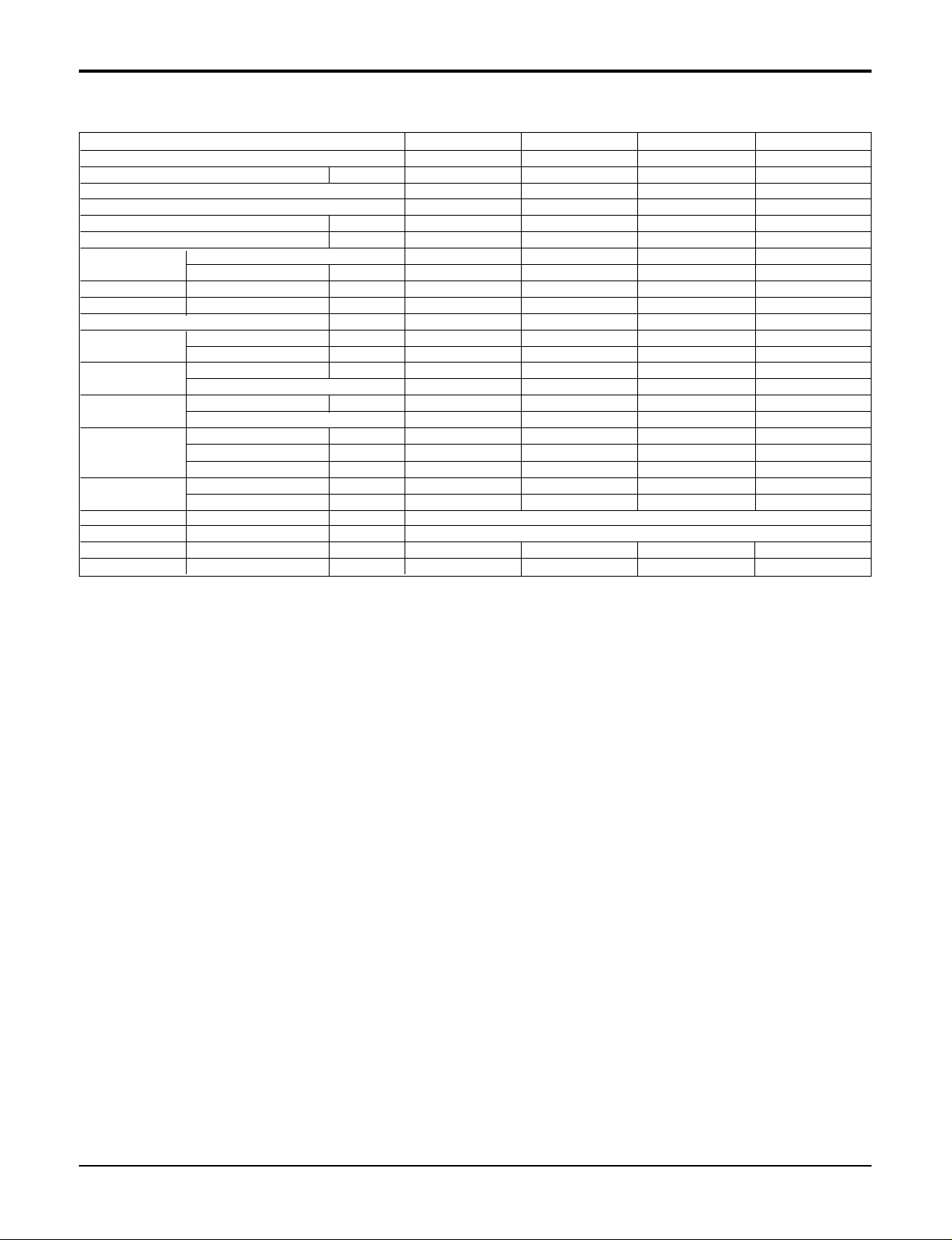
1. Split Type Indoor Unit
• There should not be any heat source or steam near the
unit.
• There should not be any obstacles to prevent the air
circulation.
• A place where air circulation in the room will be good.
• A place where drainage can be easily obtained.
• A place where noise prevention is taken into considera-
tion.
• Do not install the unit near the door way.
• Ensure the spaces indicated by arrows from the wall,
ceiling, fence, or other obstacles.
2. Art Cool Type Indoor Unit
• Do not have any heat or steam near the unit.
• Select a place where there are no obstacles in front
of the unit.
• Make sure that condensation drainage can be conveniently routed away.
Do not install near a doorway.
• Ensure that the space around the left and right of the
unit is more than 50cm. The unit should be installed
as high on the wall as possible, allowing a minimum
of 10cm from ceiling.
• Use a stud finder to locate studs to prevent unnecessary damage to the wall.
Connecting
cable
Drain hose
More than 10cm
More than 50cm
More than 50cm
More than 2m
Page 29
Service Manual 29
3. Art Cool Deluxe Type Indoor unit
• Do not have any heat or steam near the unit.
• Select a place where there are no obstacles in front of the
unit.
• Make sure that condensation drainage can be conveniently
routed away.
Do not install near a doorway.
• Ensure that the space around the left and right of the unit is
more than 20cm. The unit should be installed as high on the
wall as possible, allowing a minimum of 30cm from ceiling.
• Use a stud finder to locate studs to prevent unnecessary
damage to the wall.
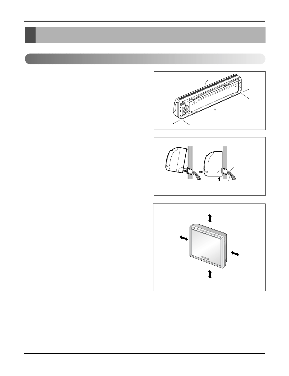
4. Duct Type Indoor Unit
Install the air conditioner in the location that satisfies the
following conditions.
• The place shall easily bear a load exceeding four times
the indoor unit’s weight.
• The place shall be able to inspect the unit as the figure.
• The place where the unit shall be leveled.
• The place shall allow easy water drainage.(Suitable
dimension “H” is necessary to get a slope to drain as figure.)
• The place shall easily connect with the outdoor unit.
• The place where the unit is not affected by an electrical
noise.
• The place where air circulation in the room will be good .
• There should not be any heat source or steam near the
unit
5. CST Type Indoor Unit
• There should not be any heat source or steam near the
unit.
• There should not be any obstacles to the air circulation.
• A place where air circulation in the room will be good.
• A place where drainage can be easily obtained.
• A place where noise prevention is taken into considera-
tion.
• Do not install the unit near the door way.
• Ensure the spaces indicated by arrows from the wall,
ceiling, or other obstacles.
• The indoor unit must have the maintenance space
around.
Unit:cm
Ceiling
Ceiling Board
Ceiling Board
30 or more
Above 250
330 or less
100
or more
50 or
more
50 or
more
30 or less
Floor
Installation
More than 20cm
More than 30cm
More than 2.3m
More than 30cm
Install the indoor unit on the wall where the height
from the floors more than 2.3 meters.
CAUTION
H
600600
Top view
(unit: mm)
Front view
Front
Inspection hole
(600X600)
Control box
1000
Page 30
30 Multi type Air Conditioner
Installation
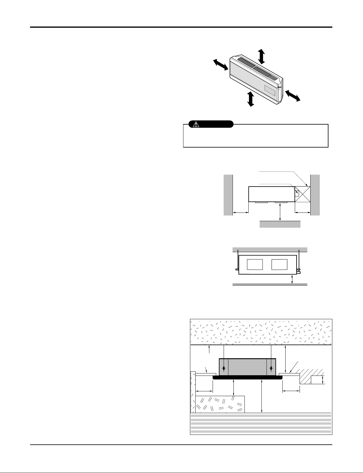
6. CVT Type Indoor Unit
• There should not be any heat source or steam near
the unit.
• There should not be any obstacles to prevent the air
circulation.
• A place where air circulation in the room will be good.
• A place where drainage can be easily obtained.
• A place where noise prevention is taken into consid-
eration.
• Do not install the unit near the door way.
• Ensure the spaces indicated by arrows from the wall,
ceiling, or other obstacles.
More than
20cm
More than eye-level
More than
20cm
R
R
More than
20cm
More than
20cm
(Ceiling installation)
(Floor/Wall installation)
Page 31

Service Manual 31
Installation
1. Room Type Indoor Unit Installation
The mounting wall should be strong and solid
enough to protect it from the vibration.
1) Mount the installation plate on the wall with
four Type "A" screws.
(If mounting the unit on the concrete wall, consider using anchor bolts.)
• Always mount the Installation plate horizontally
by aligning the marking-off line by means of the
thread and a level.
2) Drill the piping hole with 70mm dia. holecore
drill.
• Line according to the arrows marked on lower
the left and the rght side of the Installation Plate.
The meeting point of the extended line is the
center of the hole.
• Drill the piping hole at either the right or the left
and the hole should be slightly slant to the outdoor side.
Installation Plate
marking-off line
Thread
Weight
Type "A" screw
The lower left and the right side of
Installation Plate
How to fix
C
D
Ø70mm
Left rear piping Right rear piping
CHASSIS
(Grade)
SR(9/12k)
ST(18/24k)
Installation plate
Distance(mm)
BCA
12
0
A
8075SQ(7/9k)
210105
B
Ø70mm
D
12
4020400
0
Page 32

32 Multi type Air Conditioner
Installation
2. Art Cool Type Indoor Unit
The wall you select should be strong and solid enough
to prevent vibration
1) Open panel front
• First,Pull the grille bottom, then remove screws
(2 pieces), and close grille bottom again.
• The moment of lifting the both lower parts of panel
front, you can hear sound this panel came out, In
this time panel front is separated
• After pull down this panel a bit, and separate connecting wire with product.
2) Cover pipe and cover side remove
• Remove two screws(for fixing cover pipe)
• Pull up the cover side of desired connecting direc-
tion, then cover side is separated.
• In case connecting direction is left or right, path
through the hole of cover side.
NOTE: When connecting pipe path through rear
wall, don’t remove the hole.
3) Drain hose junction
• Remove the rubber stopple of desired drain direction.
• As the following picture, Insert drain hose in the handle of drain pan, and join drain hose and connecting
hose.
Panel Front
Connector
Pipe hole
CAUTION: After removing the pipe
hole, cut the burr for safety.
Page 33

Service Manual 33
Installation
■ Sticking the installation guide map and
fixing Indoor unit
■ Drill a hole in the wall
• Drill the piping hole with a ø50mm hole core drill. Drill
the piping hole at either the right or the left with the hole
slightly slanted to the outdoor side.
Plastic anchors
INSTALLATION GUIDE MAP
10m
m
INSTALLA TION GU
INSTAIIATION GUIDE MAP
INSTALLATION GUIDE MAP
1. Put an Installation Guide Map on the desired
surface.
2. Make a hole with diameter of 6mm and depth of
30-35mm when piercing a screw point.
3. Drive the fore plastic anchors into drilled points.
4. Hang the hole of product at the upper screws.
(In this time, Remove the map)
(Falling attention)
5. Check the fixed product with light power.
6. Look at suited horizon by horizontal meter on
the horizontal setting line, and Fix lightly the
map by adhesive tape.
7. Drill the piercing part for connecting pipe as
diameter 50mm. (In case of piercing rear surface)
Refer to No. 5 on this page when making a hole in the wall.
8. First, Drive the two points of the upper parts by
screws. (Leave 10mm for hanging product)
9. Drive the lower parts after facing the hole of
product with plastic anchors, and fix completely
the upper screws.
In case of nothing wrong in the matter,
connect the pipe and the wire.
(Installation manual reference)
Horizontality
IN
S
T
A
L
L
A
T
IO
N
G
U
ID
E
M
A
P
Plastic anchors
IN
S
T
A
L
L
A
T
IO
N
G
U
ID
E
M
A
P
Hanger hole
(Rear side of
product)
5-7mm
(0.2~0.3")
Indoor
WALL
Outdoor
Page 34

34 Multi type Air Conditioner
Installation
3. Art Cool Deluxe Type Indoor Unit
The wall you select should be strong and solid enough
to prevent vibration
1) Mount the installation plate on the wall with four
type A screws. If mounting the unit on a concrete
wall, use anchor bolts.
• Mount the installation plate horizontally by aligning
the centerline using a level.
2) Measure the wall and mark the centerline. It is
also important to use caution concerning the
location of the installation plate-routing of the
wiring to power outlets is through the walls typically. Drilling the hole through the wall for piping
connections must be done safely.
3). Drill a hole in the wall
• Drill the piping hole with a ø70mm hole core drill. Drill
the piping hole at either the right or the left with the
hole slightly slanted to the outdoor side.
Installation Plate
Type "A" screw
5-7mm
(3/16"~5/16")
Indoor
WALL
Outdoor
Installation plate
Ø70mm
Left rear piping Right rear piping
C
D
B
A
Ø70mm
Left rear piping Right rear piping
B
A
D
C
Installation plate
ABCD
SU
92 44 67 44
(9k, 12k)
SZ
35 33 156 33
(7k)
CHASSIS
(Grade)
Distance (mm)
(SU)
(SZ)
Page 35

Service Manual 35
Installation
4. Duct Type Indoor Unit
- BH/BG chassis
Install the unit above the ceiling correctly.
• Apply a joint-canvas between the unit and duct to
absorb unnecessary vibration.
• Apply a filter Accessory at air return hole.
• Install the unit leaning to a drainage hole side as a
figure for easy water drainage.
• A place where the unit will be leveled and that can
support the weight of the unit.
• A place where the unit can withstand its vibration.
• A place where service can be easily performed.
CASE 1
POSITION OF SUSPENSION BOLT
CASE 2
POSITION OF CONSOLE BOLT
(Unit:mm)
Drainage hole
M10 Nut
M10 SP. washer
M10 washer
X 4
X 4
(Local
supply)
X 4
M10 Nut
M10 SP. washer
M10 washer
X 4
X 4
(Local
supply)
X 4
A
B
C
1-3 mm
D
(G)
H
I
EF
NOTE:
• Throughly study the following installation locations:
1. In such places as restaurants and kitchens, considerable
amount of oil steam and flour adhere to the fan, the fin of
the heat exchanger, resulting in heat exchange reduction,
spraying, dispersing of water drops, etc.
In these cases, take the following actions:
• Make sure that the ventilation fan for smoke-collecting
hood on a cooking table has sufficient capacity so that
it draws oily steam which should not flow into the suction of the air conditioner.
• Make enough distance from a cooking room to install
the air conditioner in such a place where it may not
suck in oil steam.
2. Avoid installing air conditioner in such circumstances
where cutting oil mist or iron powder is in suspension in
factories, etc.
3. Avoid places where inflammable gas is generated, flows
in, is stored or vented.
4. Avoid places where sulfurous acid gas or corrosive gas
is generated.
5. Avoid places near high frequency generators.
932 880 355 45.5 450 30 87 750 163
1232 1180 355 45.5 450 30 87 830 186
Dimension
18k, 24k
30k, 36k
Capacity
A B C D E F (G) H I
Page 36

36 Multi type Air Conditioner
Installation
- BT chassis
Install the unit above the ceiling correctly.
• Apply a joint-canvas between the unit and duct to
absorb unnecessary vibration.
• Apply a filter Accessory at air return hole.
• Install the unit leaning to a drainage hole side as a
figure for easy water drainage.
• A place where the unit will be leveled and that can
support the weight of the unit.
• A place where the unit can withstand its vibration.
• A place where service can be easily performed.
CASE 1
POSITION OF SUSPENSION BOLT
CASE 2
POSITION OF CONSOLE BOLT
(Unit:mm)
Drainage hole
M10 Nut
M10 SP. washer
M10 washer
X 4
X 4
(Local
supply)
X 4
M10 Nut
M10 SP. washer
M10 washer
X 4
X 4
(Local
supply)
X 4
A
B
CD
1-3 mm
F
H
G
E
9/12K 708 678 434 51 537 455 230 172
18K 1060 1030 434 51 535 805 230 175
Dimension
Capacity
ABCDEFGH
Page 37

Service Manual 37
Installation
- BP chassis
Install the unit above the ceiling correctly.
• Apply a joint-canvas between the unit and duct to
absorb unnecessary vibration.
• Apply a filter Accessory at air return hole.
• Install the unit leaning to a drainage hole side as a
figure for easy water drainage.
• A place where the unit will be leveled and that can
support the weight of the unit.
• A place where the unit can withstand its vibration.
• A place where service can be easily performed.
CASE 1
POSITION OF SUSPENSION BOLT
POSITION OF CONSOLE BOLT
(Unit:mm)
C
B
A
D
G
H
F
E
Drainage hole
1-3 mm
H
I
Dimension
Capacity
9k/12k BTU/h
633 580 695 660 750 45 369 797 20 232 372
ABCDEFGHI JK
CASE 2
M10 Nut
M10 SP. washer
M10 washer
M10 washer
M10 SP. washer
M10 Nut
X 4
X 4
X 4
X 4
X 4
X 4
(Local
supply)
(Local
supply)
Page 38

38 Multi type Air Conditioner
Installation
1. Preparation of pipings
1) Cut the pipes and the cable.
• Use the accessory piping kit or the pipes purchased locally.
• Measure the distance between the indoor and
the outdoor unit.
• Cut the pipes a little longer than the measured
distance.
• Cut the cable 1.5m longer than the length of the
pipe.
2) Remove burrs.
• Remove burrs from cut edges of pipes.
• Turn the pipe end toward down to avoid the
metal powder entering the pipe.
3) Flaring the pipes.
• Insert the flare nuts, mounted on the connection
ports of both indoor and outdoor unit, onto the
copper pipes. Some refrgerant gas may leak,
when the flare nuts are removed from the indoor
unit, as some gas is charged to prevent the
inside of the pipe from rusting.
• Fit the copper pipe end into the Bar of flare tool
about 0~0.5mm higher. (See illustration)
• Flare the pipe ends.
4) Tape the flaring portion to protect it from the
dust or damages.
90
Slanted
Pipe cutter
Rough
"A"
Bar
Copper pipe
Clamp handle
Red arrow mark
Cone
Bar
Yoke
Handle
"
A": ø15.88 mm (5/8")→0~1.0 mm
ø12.7 mm (1/2")
→
0~0.5 mm
ø9.52 mm (3/8")
→
0~0.5 mm
ø6.35 mm (1/4")
→
0~0.5 mm
Piping and Drainage of Indoor Unit
CAUTION: If burrs are not removed,
they may cause a gas leakage.
When properly flared, the internal surface flare will
evenly shine and be of even thickness.
Since the flare part comes into contact with the connectors, carefully check the flare finish.
Pipe
Reamer
Point down
Inclined Cracked Uneven
= Improper flaring =
Surface
damaged
thickness
Page 39

Service Manual 39
Installation
1. Split Type Indoor Unit
• Preparing the indoor unit's piping and drain hose
for installation through the wall.
• Remove the plastic tubing retainer(see illustration
below) and pull the tubing and drain hose away
from chassis.
• Replace the plastic tubing holder in the original
position.
1. Route the indoor tubing and the drain hose in the
direction of rear left.
2. Insert the connecting cable into the indoor unit
from the outdoor unit through the piping hole.
• Do not connect the cable to the indoor unit.
• Make a small loop with the cable for easy connec-
tion later.
3.
Tape the tubing, drain hose and the connecting
cable. Be sure that the drain hose is located at the
lowest side of the bundle. Locating at the upper side
can cause drain pan to overflow inside the unit.
NOTE: If the drain hose is routed inside the room,
insulate the hose with an insulation material* so that
dripping from "sweating"(condensation) will not
damage furniture or floors.
*
Foamed polyethylene or equivalent is recommended.
4. Indoor unit installation
• Hook the indoor unit onto the upper portion of the
installation plate.(Engage the two hooks of the
rear top of the indoor unit with the upper edge of
the installation plate.) Ensure that the hooks are
properly seated on the installation plate by moving
it left and right.
Press the lower left and right sides of the unit
against the installation plate until the hooks engage
into their slots(clicking sound).
5. Connecting the pipings to the indoor unit and
drain hose to drain pipe.
• Align the center of the pipings and sufficiently
tighten the flare nut by hand.
CAUTION
When install, make sure that the
remaining parts must be removed
clearly so as not to damage the
piping and drain hose, especially
power cord and connecting cable.
For left rear piping
Connection of indoor unit piping
Loop
Tubing holder
To remove the holder,
press the bottom of
2
chassis near the holder
upward and pull the tab
out of its hole.
Press
1
Pull
Connecting
cable
Drain hose
Gas side
piping
Liquid side
piping
Connecting
cable
Drain hose
Drain hose
Indoor unit tubing
Flare nut Pipings
Page 40

40 Multi type Air Conditioner
Installation
• When extending the drain hose at the indoor unit,
install the drain pipe.
6. Wrap the insulation material around the connecting portion.
• Overlap the connection pipe insulation material
and the indoor unit pipe insulation material. Bind
them together with vinyl tape so that there is no
gap.
• Wrap the area which accommodates the rear piping housing section with vinyl tape.
• Bundle the piping and drain hose together by
wrapping them with vinyl tape over the range within which they fit into the rear piping housing section.
1. Route the indoor tubing and the drain hose to the
required piping hole position.
2. Insert the piping, drain hose and the connecting
cable into the piping hole.
3. Insert the connecting cable into the indoor unit.
• Don't connect the cable to the indoor unit.
• Make a small loop with the cable for easy connec-
tion later.
4. Tape the drain hose and the connecting cable.
• Connecting cable
5. Indoor unit installation
• Hang the indoor unit from the hooks at the top of
the installation plate.
• Insert the spacer etc. between the indoor unit and
the installation plate and separate the bottom of
the indoor unit from the wall.
Drain pipe
Connecting cable
Vinyl tape(narrow)
Adhesive
Drain pipe
Indoor unit
drain hose
Plastic bands
Insulation material
Vinyl tape(narrow)
Connection
pipe
Connecting cable
Vinyl tape
(wide)
Wrap with vinyl tape
Indoor
unit pipe
Pipe
Wrap with vinyl tape
Drain hose
Pipe
Vinyl tape(wide)
For right rear piping
Page 41

Service Manual 41
6) Connecting the pipings to the indoor unit and the
drain hose to drain pipe.
• Align the center of the pipings and sufficiently
tighten the flare nut by hand.
• When extending the drain hose at the indoor unit,
install the drain pipe.
7) Wrap the insulation material around the connecting portion.
• Overlap the connection pipe heat insulation and
the indoor unit pipe heat insulation material. Bind
them together with vinyl tape so that there is no
gap.
• Wrap the area which accommodates the rear piping housing section with vinyl tape.
• Bundle the piping and drain hose together by
wrapping them with cloth tape over the range within which they fit into the rear piping housing section.
8) Reroute the pipings and the drain hose across the
back of the chassis.
9) Set the pipings and the drain hose to the back of
the chassis with the tubing holder.
• Hook the edge of tubing holder to tap on chassis
and push the bottom of tubing holder to be
engaged at the bottom of chassis.
10) Indoor unit installation
• Remove the spacer.
• Ensure that the hooks are properly seated on the
installation plate by moving it left and right.
Press the lower left and right sides of the unit
against the installation plate until the hooks engage
into their slots(clicking sound).
Drain hose
Vinyl tape
(narrow)
Pipe
Wrap with
vinyl tape(wide)
Installation
Indoor unit tubing
Flare nut Pipings
Vinyl tape
Adhesive
Drain hose
Indoor unit drain hose
(narrow)
Plastic bands
Insulation material
Vinyl tape
(narrow)
Connection
pipe
Connecting
cable
Indoor
unit piping
Pipe
Vinyl tape
(wide)
Wrap with vinyl tape
Piping for
passage through
piping hole
Tubing holder
Hook
Push
2
1
Drain hose
Connecting
cable
Page 42

42 Multi type Air Conditioner
Installation
2. Art Cool Type Indoor Unit
• Preparing the indoor unit's piping and drain hose for
installation through the wall.
1) Route the indoor tubing and the drain hose in the
direction of rear left or right.
2) Tape the tubing, drain hose, and the connecting
cable. Be sure that the drain hose is located at the
lowest side of the bundle. Locating at the upper
side can cause drain pan to overflow inside the
unit.
NOTE: If the drain hose is routed inside the room,
insulate the hose with an insulation material* so that
dripping from "sweating"(condensation) will not damage
furniture or floors.
*Foamed polyethylene or equivalent is recommended.
3) Connecting the pipings to the indoor unit and drain
hose to drain pipe.
• Align the center of the pipes and sufficiently tighten
the flare nut by hand.
• Tighten the flare nut with a wrench.
• When extending the drain hose at the indoor unit,
install the drain pipe.
4) Wrap the insulation material around the connecting
portion.
• Overlap the connection pipe insulation material and
the indoor unit pipe insulation material. Bind them
together with vinyl tape so that there is no gap.
• Wrap the area which accommodates the rear piping
housing section with vinyl tape.
• Bundle the piping and drain hose together by wrapping them with vinyl tape for enough to cover where
they fit into the rear piping housing section.
Connecting
cable
Gas side piping
Liquid side piping
Drain hose
Loop
Indoor unit tubing Flare nut Pipes
Wrench
Indoor unit tubing
Open-end wrench (fixed)
Connection pipe
Flare nut
Vinyl tape(narrow)
Adhesive
Drain pipe
Indoor unit drain hose
Plastic bands
Insulation material
Vinyl tape(narrow)
Connection
pipe
Connecting cable
Vinyl tape
(wide)
Wrap with vinyl tape
Indoor
unit pipe
Pipe
Wrap with vinyl tape
Drain hose
Pipe
Vinyl tape(wide)
Page 43

Service Manual 43
Installation
■ Panel Assembly
1. First, Check the side cover assembly exactly, Fix
power cord in the bottom groove of cover side
left.
2. Assemble connecting lead wire with controller
and first fix the upper part of panel front, then
match the lower part of panel front
3. Drive two screws.
Panel F ront
Connector
Page 44

44 Multi type Air Conditioner
Installation
3. Art Cool Deluxe Type Indoor Unit
Connection of piping Indoor
• Preparing the indoor unit's piping and drain hose for
installation through the wall.
• Remove the plastic tubing retainer(see illustration
below) and pull the tubing and drain hose away from
chassis.
•
Replace the plastic tubing holder in the original position.
(Optional)
1. Route the indoor tubing and the drain hose in the
direction of rear right.
2. Insert the connecting cable into the indoor unit
from the outdoor unit through the piping hole.
• Do not connect the cable to the indoor unit.
• Make a small loop with the cable for easy
connection later.
3. Tape the tubing, drain hose, and the connecting
cable. Be sure that the drain hose is located at the
lowest side of the bundle. Locating at the upper
side can cause drain pan to overflow inside the
unit.
NOTE: If the drain hose is routed inside the room,
insulate the hose with an insulation material* so that
dripping from "sweating"(condensation) will not damage
furniture or floors.
*Foamed polyethylene or equivalent is recommended.
4. Indoor unit installation
• Hook the indoor unit onto the upper portion of the
installation plate.(Engage the two hooks of the rear
top of the indoor unit with the upper edge of the installation plate.) Ensure that the hooks are properly seated on the installation plate by moving it left and right.
Press the lower left and right sides of the unit against
the installation plate until the hooks engage into their
slots(clicking sound).
4. Connecting the pipings to the indoor unit and drain
hose to drain pipe.
• Align the center of the pipes and sufficiently tighten
the flare nut by hand.
• Tighten the flare nut with a wrench.
• When extending the drain hose at the indoor unit,
install the drain pipe.
For right rear piping
Connecting
cable
Drain hose
Drain hose
Tape
Connecting
pipe
Drain hose
Connecting cable
Indoor unit tubing Flare nut Pipes
Open-end wrench (fixed)
Flare nut
Wrench
Indoor unit tubing
Connection pipe
Page 45

Service Manual 45
Installation
5. Wrap the insulation material around the connecting
portion.
• Overlap the connection pipe insulation material and
the indoor unit pipe insulation material. Bind them
together with vinyl tape so that there is no gap.
• Wrap the area which accommodates the rear piping
housing section with vinyl tape.
• Bundle the piping and drain hose together by wrapping them with vinyl tape for enough to cover where
they fit into the rear piping housing section.
1. Route the indoor tubing and the drain hose to the
required piping hole
position.
2. Insert the piping, drain hose, and the connecting
cable into the piping hole.
3. Insert the connecting cable into the indoor unit.
• Don't connect the cable to the indoor unit.
•
Make a small loop with the cable for easy connection later.
4. Tape the drain hose and the connecting cable.
• Connecting cable
5. Indoor unit installation
• Hang the indoor unit from the hooks at the top of the
installation plate.
• Insert the spacer etc. between the indoor unit and the
installation plate and separate the bottom of the
indoor unit from the wall.
6. Connecting the pipings to the indoor unit and the
drain hose to drain pipe.
• Align the center of the pipes and sufficiently tighten
the flare nut by hand.
• Tighten the flare nut with a wrench.
• When extending the drain hose at the indoor unit,
install the drain pipe.
Plastic bands
Insulation material
Vinyl tape(narrow)
Connection
pipe
Connecting cable
Vinyl tape
(wide)
Wrap with vinyl tape
Indoor
unit pipe
Pipe
For left rear piping
Wrap with vinyl tape
Pipe
Indoor unit
Spacer
Installation plate
8cm
Vinyl tape(wide)
Drain hose
Connecting cable
Drain pipe
Indoor unit tubing Flare nut Pipes
Open-end wrench (fixed)
Flare nut
Wrench
Indoor unit tubing
Connection pipe
Drain hose
Indoor unit drain hose
Adhesive
Vinyl tape
(narrow)
Page 46

46 Multi type Air Conditioner
Installation
7. Wrap the insulation material around the connecting portion.
• Overlap the connection pipe heat insulation and the
indoor unit pipe heat insulation material. Bind them
together with vinyl tape so that there is no gap.
• Wrap the area which accommodates the rear piping
housing section with vinyl tape.
• Bundle the piping and drain hose together by wrapping them with cloth tape over the range within which
they fit into the rear piping housing section.
8. Reroute the pipings and the drain hose across the
back of the chassis.
9. Set the pipings and the drain hose to the back of
the chassis with the tubing holder.
• Hook the edge of tubing holder to tap on chassis and
push the bottom of tubing holder to be engaged at the
bottom of chassis.
10. Indoor unit installation
• Remove the spacer.
• Ensure that the hooks are properly seated on the
installation plate by moving it left and right.
Press the lower left and right sides of the unit against
the installation plate until the hooks engage into their
slots(clicking sound).
Plastic bands
Insulation material
Vinyl tape(narrow)
Connection
pipe
Connecting cable
Indoor
unit piping
Pipe
Vinyl tape
(wide)
Wrap with vinyl tape
Drain hose
Vinyl tape(narrow)
Pipe
Wrap with
vinyl tape(wide)
Piping for
passage through
piping hole
Tubing holder
Drain hose
Connecting
cable
Page 47

Service Manual 47
Installation
• Bad case
■
Following bending type from right to left could cause problem
of pipe damage.
Installation Information (For left piping)
• Good case
For left piping. Follow the instruction below.
• Press on the upper side of clamp. ( )
• Bend the tubing to the left side of chassis.
• Bend the tubing to the left side of chassis.
CAUTION
Page 48

48 Multi type Air Conditioner
Installation
4. Duct Type Indoor Unit
1) Indoor Unit Installation
• Select and mark the position for fixing bolts.
• Drill the hole for set anchor on the face of ceiling.
• Insert the set anchor and washer onto the suspen-
sion bolts for locking the suspension bolts on the ceiling.
• Mount the suspension bolts to the set anchor firmly.
• Secure the installation plates onto the suspension
bolts (adjust level roughly) using nuts, washers and
spring washers.
1 Set anchor
Old building New building
2 Plate washer
3 Spring washer
4 Nut
5 Suspension
bolts
• Local supply
➀ Set anchor
➁ Plate washer - M10
➂ Spring washer - M10
➃ Nut - W3/8 or M10
➄ Suspension bolt - W3/8 or M10
CAUTION: Tighten the nut and bolt to
prevent unit falling.
Page 49

Service Manual 49
5. CVT Type Indoor Unit
- VB chassis
■ Before Installing, prepare Installation Plates
• 'Installation Plates' are attached at the bottom of
indoor unit.
Detach them by removing each 3 screws at both
sides.
• Detach 'Side Plate (R,L)' by removing each 2 screws
on both sides.
• Pull the upper right and left side of 'Inlet Grille' to the
front, and it will stop at slightly tilted position.
• Unhook the 'Inlet hanger' from the 'Hanger screw' on
the both left and right side.
• Detach the 'Inlet Grille' from the Indoor Unit.
1) Installation on the ceiling
• Measure and mark the position for the
Suspension bolts and the piping hole.
• Drill the hole for anchor nut on the ceiling.
Before secure the Installation Plates, select the bent
direction of the Installion Plate to the inside or the
outside according to the installation circumstances.
• Drill the piping hole on the wall slightly tilted to the
outdoor side using a ø70 hole-core drill.
R
1076
Suspension
bolt
Center-line for the
piping hole
265
1236
265
Install Plate
1)
2)
R
Side Plate
Inlet Grille
Inlet hanger
Hanger
screw
Installation
Indoor Outdoor
WALL
5~7mm
Page 50

50 Multi type Air Conditioner
• Insert the nuts and washer onto the suspension bolts
for locking the suspension bolts on the ceiling.
• Mount the suspension bolts to the anchor-nuts firmly.
• Secure the Installation plates onto the Suspension
bolts (adjust level roughly.) using nuts, washers and
spring washers.
• Engage 2 hooks on the both left and right side
of the unit to the lower slot of Installation Plates.
• Adjust a level with a level gauge on the direction
of left-right, back-forth by adjusting suspension
bolts.
• Move the hooks on the unit to the upper slot of
Installation Plates. Then the unit will be declined
to the bottomside so as to drain well.
Washer
Nut
Suspension
bolts
Ceiling
Anchor nut
Suspension
bolts
Spring
washer
max.
12mm
Washer
Nut
1)
2)
Suspension
bolt
Installation plate
Adjust a level
R
Level gauge
Lower slot
R
R
Upper slot
Installation
Page 51

Service Manual 51
Installation
- VE chassis
The wall you select should be strong and solid
enough to prevent vibration
1. Mount the installation plate on the wall with
type "A" screws. If mounting the unit on a concrete wall, use anchor bolts.
• Mount the installation plate horizontally by aligning
the centerline using a level.
2. Measure the wall and mark the centerline. It is
also important to use caution concerning the
location of the installation plate-routing of the
wiring to power outlets is through the walls typically. Drilling the hole through the wall for piping
connections must be done safely.
Mounting the anchor Nut & Bolt
(Ceiling Mounting)
• Prepare 4 suspension bolts (Each bolts length
should be same.)
• Measure and mark the position for the Suspension
bolts and the piping hole.
• Insert the nuts and washer onto the suspension
bolts for locking the suspension bolts on the ceiling.
• Mount the suspension bolts to the anchor-nuts
firmly.
Installation Plate
Type "A" screw
Installation plate
ABCDE
VE 180 115 - 115 50
CHASSIS
(Grade)
Distance (mm)
C
D
Ø70mm
Left rear piping Right rear piping
Installation plate
A
B
Ø70mm
Installation plate
D
CE A
Left rear piping
Right rear piping
B
Ø70mm
Page 52

52 Multi type Air Conditioner
Installation
• Secure the Installation plates onto the Suspension
bolts (adjust level roughly.) using nuts, washers and
spring washers.
• Engage 2 hooks on the both left and right side of the
unit to the lower slot of Installation Plates.
• Adjust a level with a level gauge on the direction of
left-right, back-forth by adjusting suspension bolts.
• Move the hooks on the unit to the upper slot of
Installation Plates. Then the unit will be declined to
the bottomside so as to drain well.
Drill a Hole in the Wall
• Drill the piping hole with a ø70mm hole core drill.
Drill the piping hole at either the right or the left with
the hole slightly slanted to the outdoor side.
5-7mm
(3/16"~5/16")
Indoor
WALL
Outdoor
Anchor nut
Ceiling
Nut
Suspension
bolts
Center-line for the
piping hole
Washer
820
Suspension bolt
Suspension
Spring
washer
Hangen
Max.
12mm
235
bolts
Nut
Washer
Page 53

Service Manual 53
Drain hose
Ceiling
Ceiling
Ceiling
Front of view
Side of view
1. Install declination of the indoor unit is very important for the drain of the convertible type air
conditioner.
2. Minimum thickness of the insulation for the connecting pipe shall be 7mm.
3. If the Installation Plates are fixed to horizontal line, the indoor unit after installing will be declined
to the bottomside.
CAUTION
• The unit must be horizontal or declined to the drain hose connected when finished installation.
• The unit must be declined to the bottomside of the unit when finished installation.
Installation
CAUTION: Installation Information For Declination
Page 54

54 Multi type Air Conditioner
R
R
R
1
2
•
Before working, refer to "Connecting pipe
and cable to Indoor Unit".
R
Inlet hanger
Hook
Cabinet Bottom
• Secure the unit to the Installation Plates with four M8
bolts and washers.
• Hook up the Inlet Grille Hook to the cabinet.
• Hang the Inlet Hanger to the screw.
• Fit the projection hooks of the side plates to the 'Side
Panel' and the 'Front Panel' by lifting it.
• Fasten the screws.
Installation
Page 55

Service Manual 55
1076
more than
260
265
Washer
Nut
Wall
Anchor nut
Spring
washer
Wall
5~7mm
Less than
12mm
1236
Indoor Outdoor
2) Installation on the Wall
• Select and mark the position for fixing bolts and piping
hole.
Decide the position for fixing bolts slightly tilted to the
drain direction after considering the direction of drain
hose.
• Drill the hole for anchor nut on the wall.
• Drill the piping hole on the wall slightly tilted to the out-
door side using a ø70 hole-core drill.
• Secure the 'Install Plate' onto the wall with four anchor
bolts, washers and spring washers.
Before secure the Install Plates, select the bent direction of the 'Install Plate' to the inside or outside according to the installation circumstances.
Installation
Page 56

56 Multi type Air Conditioner
Install the Indoor unit onto Installation Plate.
• Insert 2 hooks on the both left and right side of the unit
to the inner slot (wall side) of the Installation Plate.
• Secure the unit to the Installation Plate with four M8
bolts and washers.
• Hook up the Inlet Grille Hook to the cabinet.
• Hang the Inlet Hanger to the screw.
• Fit the projection hooks of the side plates to the 'Side
Panel' and the 'Front Panel' by lifting it.
• Fasten the screws.
R
2
1
•
Before working, refer to "Connecting pipe
and cable to Indoor Unit".
Inner slot
Installation
Page 57

Service Manual 57
3) Installation on the floor
Installation of Mount Bracket.
• Select and mark the position for Mount Brackets and
the piping hole.
• Drill the hole for the anchor nut on the wall.
• Drill the piping hole using a ø70 hole-core drill.
• Secure the Mount Brackets on the wall with four M4
screws.
Install the indoor unit onto the Mount Brackets.
• Engage the slot at the back of the unit with Mount
Bracket.
• Drill the piping hole with 70mm dia, hole core drill.
• Piping hole should be slightly slant to the outdoor side.
After Installing, reassemble detached parts.
• Hang the 'Inlet Grille' and hook the 'Inlet Hanger' to the
Hanger Screw.
• Assemble the 'Side Plates(R,L)' with 2 screws on both
left and right side.
Floor mount
bracket
Slot
Floor mount
bracket
Install plate
Slot
Piping hole
Wall
5~7mm
Indoor Outdoor
more than 760mm
From the left wall
From the
right wall
448mm
more than 840mm
Wall
Installation
Page 58

58 Multi type Air Conditioner
6. Ceiling Cassette Type Indoor Unit
- TC chassis
1) Ceiling opening dimensions and hanging bolt location
NOTE:
• Avoid the following installation location.
1. Such places as restaurants and kitchen where considerable amount of oil steam and flour is generated.
These may cause heat exchange efficiency reduction, or water drops, drain pump mal-function.
In these cases, take the following actions;
• Make sure that ventilation fan is enough to cover all noxious gases from this place.
• Ensure enough distance from the cooking room to install the air conditioner in such a place where it may
not suck oily steam.
2. Avoid installng air conditioner in such places where cooking oil or iron powder is generated.
3. Avoid places where inflammable gas is generated.
4. Avoid place where noxious gas is generated.
5. Avoid places near high frequency generators.
Ceiling board
Level gauge
Ceiling
1,000 (Ceiling opening)
931.6
893.4 (Hanging bolt)
328.4 (Hanging bolt)
860
390
30.8
430 (Ceiling opening)
Use the ventilation fan
for smoke-collecting
hood with sufficient
capacity.
Cooking table
Air conditioner
Take enough
distance
• The dimensions of the paper model for installing are
the same as those of the ceiling opening dimensions.
• Select and mark the position for fixing bolts and piping hole.
• Decide the position for fixing bolts slightly tilted to
the drain direction after considering the direction of
drain hose.
• Drill the hole for anchor bolt on the wall.
• This air-conditioner uses a drain pump.
• Install the unit horizontally using a level gauge.
• During the installation, care should be taken not to
damage electric wires.
Installation
CAUTION
Page 59

Service Manual 59
Wall
5~7mm
Indoor Outdoor
Set screw of
paper model (4 pieces)
Paper model
for installation
Ceiling board
103mm
Adjust the same height
Ceiling board
Ceiling
Flat washer for M10
(accessory)
Keep the length of the bolt
from the bracket to 40mm
Open the ceiling board
along the outer edge of the
paper model
Flat washer for M10
(accessory)
Hanging bolt
(W3/8 or M10)
Nut
(W3/8 or M10)
Nut
(W3/8 or M10)
Spring washer
(M10)
Air Conditioner body
• The following parts are local purchasing.
Hanging Bolt - W 3/8 or M10
Nut - W 3/8 or M10
Spring Washer - M10
Plate Washer - M10
• Drill the piping hole on the wall slightly tilted to the
outdoor side using a Ø 70 hole-core drill.
• Tighten the nut and bolt to prevent unit from
falling off.
2) Indoor Unit Installation
Installation
CAUTION
Page 60

60 Multi type Air Conditioner
7. Ceiling Cassette Type Indoor Unit
- TE/TF/TD chassis
1) Ceiling opening dimensions and hanging bolt location
Ceiling board
Level gauge
Ceiling
Unit:mm
744 Unit size
744 Unit size
658 (Hanging bolt)
6666
790 (Ceiling opening)
790 (Ceiling opening)
572(Hanging bolt)
109
109
Unit:mm
570 Unit size
570 Unit size
450 (Hanging bolt)
7575
600 (Ceiling opening)
600 (Ceiling opening)
521(Hanging bolt)
39.5
39.5
Unit:mm
840 Unit size
840 Unit size
672 (Hanging bolt)
101.5101.5
875 (Ceiling opening)
875 (Ceiling opening)
785 (Hanging bolt)
45
45
TE
TF
TD
• The dimensions of cardboard for installing are the
same as those of the ceiling opening dimensions.
• Select and mark the position for fixing bolts and piping hole.
• Decide the position for fixing bolts slightly tilted to the drain
direction after considering the direction of drain hose.
• Drill the hole for anchor bolt on the wall.
• This air-conditioner uses a drain pump.
• Install the unit horizontally using a level gauge.
• During the installation, be careful not to damage
electric wires.
Installation
CAUTION
Page 61

Service Manual 61
Set screw of
cardboard (4 pieces)
Cardboard
for installation
Ceiling board
150mm
Adjust the same height
Ceiling board
Ceiling
Flat washer for M10
(accessory)
Keep the length of the bolt
from the bracket to 40mm
Open the ceiling board
along the outer edge of the
paper model
Flat washer for M10
(accessory)
Hanging bolt
(W3/8 or M10)
Nut
(W3/8 or M10)
Nut
(W3/8 or M10)
Spring washer
(M10)
Air Conditioner body
2) The Indoor Unit Installation
• The following parts are local purchasing.
Hanging Bolt - W 3/8 or M10
Nut - W 3/8 or M10
Spring Washer - M10
Plate Washer - M10
• Drill the piping hole on the wall slightly tilted to the
outdoor side using a Ø 70 hole-core drill.
• Tighten the nut and bolt to prevent the unit from
falling off.
Installation
NOTE:
• Avoid the following installation location.
1. Such places as restaurants and kitchen where considerable amount of oil steam and flour is generated.
These may cause heat exchange efficiency reduction, or water drops, drain pump mal-function.
In these cases, take the following actions;
• Make sure that ventilation fan is enough to cover all noxious gases from this place.
• Ensure enough distance from the cooking room to install the air conditioner in such a place where it may
not suck oily steam.
2. Avoid installng air conditioner in such places where cooking oil or iron powder is generated.
3. Avoid places where inflammable gas is generated.
4. Avoid place where noxious gas is generated.
5. Avoid places near high frequency generators.
Use the ventilation fan
for smoke-collecting
hood with sufficient
capacity.
Cooking table
Air conditioner
Take enough
distance
CAUTION
Wall
Indoor Outdoor
5~7mm
Page 62

62 Multi type Air Conditioner
Remote control
box body
Cord clamp
(accessory)
Lever carefully
the box open
using a screw
driver, etc.
Front case
The lower part
Face of wall
Under plate
Screw (accessory)
• Fix the under plate on the wall
• Separate the under plate from Remote control box.
• Fix the cord clamps on the wall by ø 3 tapping
screws (accessory).
• Fix the remote control cord.
WIRED REMOTE CONTROL INSTALLATION
DISASSEMBLING
ELECTRICAL WIRING
Wire and make sure that teminal
numbers are matched on unit side and
remote controller side.
The maximum length of the cord is 100m.
If the length of the cord exceeds 50m,
use a wire size greater than 0.5mm
2
.
Remote controller
(Main board)
CN REMO
• Although the room temperature sensor is in the indoor unit, the remote controller should be installed
in such places away from direct sunlight and high humidity.
Installation of the remote controller
• Select places that are not splashed with water.
• Select control position after receiving customer approval.
• The room temperature sensor is built in the indoor unit.
• This remote controller equipped with liquid crystal display. If this position is higher or lower, display is difficult
to see.(The standard height is 1.2 ~ 1.5m high)
Routing of the remote controller cord
• Keep the remote controller cord away from the refrigerant piping and the drain piping.
• To protect the remote controller cord from electrical noise, place the cord at least 5cm away from other power
cables (audio equipment, television set, etc.)
• If the remote controller cord is secured to the wall, provide a trap at the top of the cord to prevent water
droplets from running.
Remote Controller Installation
Installation
Page 63

Service Manual 63
Installation
Remove the battery cover from the remote controller.
• Slide the cover according to the arrow direction.
Insert the two batteries.
• Be sure that the (+) and (-) directions are correct.
• Be sure that both batteries are new.
Re-attach the cover.
• Slide it back into position.
REMOTE CONTROL PREPARATION(OPTIONAL)
HOW TO MOUNT ONTO A WALL
HOW TO INSERT BATTERIES
• Do not use rechargeable batteries,
such batteries differ from standard dry
cells in shape, dimensions, and performance.
• Romove the batteries from the remote
controller if the air conditioner is not
going to be used for some long time.
HOW TO INSERT BATTERIES
Page 64

64 Multi type Air Conditioner
Installation
CAUTION: After the confirmation of the above conditions, prepare the wiring as
follows:
1) Never fail to have an individual power specialized for the air conditioner. As for the method of wiring,
be guided by the circuit diagram pasted on the inside of control box cover.
2) The means for disconnection from a power supply shall be incorporated in the fixed wiring and
have an air gap contact separation of at least 3mm in each active(phase) conductors.
3) The screw which fasten the wiring in the casing of electrical fittings are liable to come loose from
vibrations to which the unit is subjected during the course of transportation. Check them and
make sure that they are all tightly fastened. (If they are loose, it could give rise to burn-out of the
wires.)
4) Specification of power source.
5) Confirm that electrical capacity is sufficient.
6) See to that the starting voltage is maintained at more than 90 percent of the rated voltage marked
on the name plate.
7) Confirm that the cable thickness is as specified in the power sources specification.
(Particularly note the relation between cable length and thickness.)
8) Never fail to equip a leakage breaker where it is wet or moist.
9) The following troubles would be caused by voltage drop-down.
• Vibration of a magnetic switch, damage on the contact point there of, fuse breaking, disturbance to the
normal function of a overload protection device.
• Proper starting power is not given to the compressor.
1.
Connecting the pipings to the Outdoor
unit
1) When piping installation work you must be used the
connector.
2) Align the center of the pipings and sufficiently tighten the flare nut by hand
3) Finally, tighten the flare nut with torque wrench until
the wrench clicks.
■ When tightening the flare nut with torque wrench,
ensure the direction for tightening follows the arrow on
the wrench.
*Connecting pipe size
Indoor Units
Gas
Liquid
A → B
18K/24K Ø9.52→Ø12.7 Not available
30K/36K Ø9.52 →Ø15.88 Not available
Indoor Units Gas side Liquid side
7K/9K/12K Ø9.52(3/8) Ø6.35(1/4)
18K/24K Ø12.7(1/2) Ø6.35(1/4)
30K/36K Ø15.88(5/8) Ø6.35(1/4)
A
B
Connector
Gas side piping
Liquid side piping
Torque wrench
B-UNIT
A-UNIT
Outdoor unit
Connecting Pipings and the cable to Outdoor unit
Page 65

Service Manual 65
Installation
The power cord connected to the outdoor unit
should be complied with the following specifications (Rubber insulation, type H05RN-F
approved by HAR or SAA).
The connecting cable connected to the indoor
and outdoor unit should be complied with the
following specifications (Rubber insulation, type
H07RN-F approved by HAR or SAA).
NORMAL CROSSSECTIONAL AREA
0.75mm
2
NORMAL CROSS
SECTIONAL AREA
3.5mm2 (18k~30k Btu)
5.0mm2 (31k~56k Btu)
Air
Conditioner
Main power source
Circuit Breaker
Use a 30A circuit
breaker or time
delay fuse.
CAUTION: If a power plug is not to be used, provide a circuit breaker between
power source and the unit as shown below.
Circuit Breaker
18k~30k Btu 25A
31k~40k Btu 60A
41k~56k Btu 75A
CAUTION
ø8.5mm
GN/YL
20mm
ø7.5mm
GN/YL
20mm
Page 66

66 Multi type Air Conditioner
Checking the Drainage and Pipe forming
Pull the right and
the left side.
Screw
1. Split Type Indoor Unit
1) Remove the Grille from the cabinet
• Set the up-and-down air direction louver to
open position(horizontally) by finger pressure.
• Remove the securing screws.
• To remove the Grille, pull lower the left and
right side of the grille toward you (slightly tilted)
and lift it straight upward.
2) Check the drainage
• Pour a glass of water on the evaporator.
• Ensure if water flows drain hose of indoor unit
without any leakage.
2. Art Cool Type Indoor Unit
• Pour a glass of water on the evaporator.
• Ensure the water flows through the drain hose of
the indoor unit without any leakage and goes out
the drain exit.
Installation
Page 67

Service Manual 67
Installation
3. Art Cool Deluxe Type Indoor Unit
1) To remove the front panel from the indoor unit.
• Set the air direction louvers up-and-down to the position(horizontally) by hand.
• Remove the securing screws that retain the front
panel. Pull the lower left and right sides of the grille
toward you and lift it off.
2) To check the drainage.
• Pour a glass of water on the evaporator.
• Ensure the water flows through the drain hose of the
indoor unit without any leakage and goes out the drain
exit.
3) Drain piping
• The drain hose should point downward for easy drain
flow.
• Do not make drain piping.
Air
filter
Inlet Grille
Do not raise
Water
leakage
Tip of drain hose
dipped in water
Water
leakage
Ditch
Accumulated
drain water
Air
Waving
Water
leakage
Downward slope
Less than
50mm gap
Connecting area
drain hose
Leakage
checking
Page 68

68 Multi type Air Conditioner
Installation
4. Convertible Type Indoor Unit
To remove the front panel from the indoor
unit.
1. Set the air direction louvers up-and-down to the position(horizontally) by hand.
2. Remove the securing screws that retain the front
panel. Pull the lower left and right sides of the grille
toward you and lift it off.
To check the drainage.
1. Pour a glass of water on the evaporator.
2. Ensure the water flows through the drain hose of the
indoor unit without any leakage and goes out the
drain exit.
Drain piping
1. The drain hose should point downward for easy drain
flow.
2. Do not make drain piping like the following.
Pull the right and
the left side.
Accumulated
drain water
Air
Waving
Water
leakage
Do not raise
Water
leakage
Water
leakage
Tip of drain hose
dipped in water
Ditch
Downward slope
Less than
50mm gap
Page 69

Service Manual 69
Installation
Ceiling
1~3mm
Drainage hole
Drainage hole
U-Trap
B
C
A ≥ 70mm
B ≥ 2C
C ≥ 2 x SP
SP = External Pressure
(mmAq)
Ex) External Pressure
= 10mmAq
A ≥ 70mm
B ≥ 40mm
C ≥ 20mm
A
Make sure to be closed.
Unit
Drainage pipe
(Local supply)
Thermal insulator
(Local supply)
Drainage hole
CAUTION FOR GRADIENT OF
UNIT AND DRAIN PIPING
Lay the drain hose with a downware
inclination so water will drain out.
700mm
(Drain pump model only)
Front of view
• Always lay the drain with downward inclination
(1/50 to 1/100).
Prevent any upward flow or reverse flow in any part.
• 5mm or thicker formed thermal insulator shall
always be provided for the drain pipe.
1. Install declination of the indoor unit is very important for the drain of the duct type air conditioner.
2. Minimum thickness of the insulation for the connecting pipe shall be 5mm.
• The unit must be horizontal or declined to the drain hose connected when finished installation.
CORRECT
INCORRECT
• Upward routing not
allowed
Applied U-Trap Dimension
• Install the P-Trap (or U-Trap) to prevent
a water leakage caused by the blocking
of intake air filter.
INCORRECT
CORRECT
5. Duct Type Indoor Unit
Page 70

70 Multi type Air Conditioner
Installation
6. CST Type Indoor Unit
• Drain piping must have down-slope (1/50 to 1/100):
be sure not to provide up-and-down slope to prevent
reversal flow.
• During drain piping connection, be careful not to
exert extra force on the drain port on the indoor
unit.
• The outside diameter of the drain connection on
the indoor unit is 32mm.
•
Be sure to install heat insulation on the drain piping.
Piping material: Polyvinyl chloride pipe VP-25
and pipe fittings
Heat insulation material: Polyethylene foam with
thickness more than 8 mm.
The air conditioner uses a drain pump to drain water.
Use the following procedure to test the drain pump operation:
• Connect the main drain pipe to the exterior
and leave it provisionally until the test comes
to an end.
• Feed water to the flexible drain hose and
check the piping for leakage.
• Be sure to check the drain pump for normal
operating and noise when electrical wiring is
finished.
• When the test is completed, connect the flexible drain hose to the drain port on the indoor
unit.
Drain test
Feed water
Drain Pump
Drain pan
Flexible drain hose
(accessory)
Main
drain pipe
Glue the joint
Drain
port
Drain hose connection
Use the clip (accessory)
Maintenance
drain port
Upward
routing
not allowed
Pipe clamp
Indoor unit
1/50~1/100
MAX 700mm
Page 71

Service Manual 71
Maximum Length of Pipe and Extra Charge of Refrigerant Charge
Installation
It does not matter which unit is higher.
Standard Length
A,B,C,D A B C D
A2UW146FA0
A2UW186FA0
A3UW186FA0
7.5m 25m 25m - - 40m(A+B)
A3UW246FA0
A4UW246FA0
7.5m 25m 25m 25m - 50m(A+B+C)
A4UW306FA0 7.5m 25m 25m 25m 25m 70m(A+B+C+D)
Max piping length each indoor unit
Model
[Outdoor Unit]
Max total piping length
1.1 The maximun allowable level and piping length
15m
7.5m
A
B
C
D
[Outdoor Unit]
[Indoor Unit]
1. TPS Inverter Multi -Multi Piping Type
Indoor Unit Capacity Pipe Size Rated Max Additional
(Btu/h)
Gas Liquid
Length Length Refrigerant
7k, 9k, 12k 3/8"(9.52mm) 1/4"(6.35mm) 7.5m 25m 25g/m
18k, 24k 1/2"(12.7mm) 1/4"(6.35mm) 7.5m 25m 35g/m
1.2 Refrigerant Charge
❈ Extra refrigerant = (Extended length - Rated length) x Additional refrigerant
Page 72

72 Multi type Air Conditioner
Installation
2. TPS Inverter Multi - Distributor Type
2.1 The maximum allowable level and piping length
L
1
L
2
L
3
L
4
L
5
L
6
30m
Installation of the outdoor unit
in an upper position
10m
A
B
Outdoor Unit
30m
10m
Installation of the outdoor unit
in a lower position
• Total main piping length : 50m( + )
• Total branch piping length : 50m(
L
1+L2
+ L3+L4+L5+L6)
• Each branch piping length : 15m(L1,L2,L3,L4,L5,L6)
• Total system piping length : 100m(40+60)
A
B
Place the BD unit and
indoor units within a
level distance of 10m
from each other.
BD Unit
Main piping
Branch piping
Place the BD unit and
indoor units within a
level distance of 10m
from each other.
Outdoor Unit
BD Unit
BD Unit
BD Unit
R
R
Page 73

Service Manual 73
Installation
• A7UW486FA0
Outdoor Unit
Installation of the outdoor unit
in an upper position
A
BD Unit
30
m
B
Main piping
Branch piping
• Total main piping length : 50m( + )
• Total branch piping length : 60m(
• Each branch piping length : 15m(
BD Unit
A
L
L
• Total system piping length : 110m(50+60)
B
+ L3+L4+L5+L6 +L7)
1+L2
1,L2,L3,L4,L5,L6 ,L7
Place the BD unit and
indoor units within a
L
1
L
2
L
3
L
4
L
5
L
6
L
7
R
level distance of 10m
from each other.
10m
)
R
Outdoor Unit
BD Unit
BD Unit
10m
Installation of the outdoor unit
in a lower position
Place the BD unit and
indoor units within a
level distance of 10m
from each other.
30m
Page 74

74 Multi type Air Conditioner
Installation
• A8UW486FA0
Outdoor Unit
Installation of the outdoor unit
in an upper position
A
30m
B
Main piping
Branch piping
• Total main piping length : 50m( + )
A
• Total branch piping length : 70m(
• Each branch piping length : 15m(
• Total system piping length : 120m(50+70)
BD Unit
BD Unit
B
L
+ L3+L4+L5+L6 +L7 +L8)
1+L2
L
1,L2,L3,L4,L5,L6 ,L7 ,L8
Place the BD unit and
indoor units within a
L
1
L
2
L
3
L
4
L
5
L
6
L
7
L
8
R
level distance of 10m
from each other.
10m
)
R
Outdoor Unit
BD Unit
BD Unit
10m
Installation of the outdoor unit
in a lower position
Place the BD unit and
indoor units within a
level distance of 10m
from each other.
30m
Page 75

Service Manual 75
Installation
2.2 Refrigerant charge
The calculation of the additional charge should be taken in account for the length of pipe.
Caution
Regulation for refrigerant leakage(in Europe)
: the amount of refrigerant leakage should satisfy the following equation for human safety.
❐ If the above equation can not be satisfied, then follow the following steps.
- Selection of air conditioning system: select one of the next
1. Effective opening part Installation
2. Reconfirmation of outdoor unit capacity and piping length
3. Reduction of the amount of refrigerant
4. 2 or more security device installation of alarm for gas leakage
- Change indoor unit type
: installation position should be over 2m from the floor (Wall mounted type → Cassette type)
- Adoption of ventilation system
: choose ordinary ventilation system or building ventilation system
- Limitation in piping work
: design for earthquake-proof and prevention against thermal stress
Total amount of refrigerant in the system
0.3 ( kg / m3)
Volume of the room at which indoor unit of the least capacity is installed
A6UW406FA0 charge = 4100g
A
Additional charge (g)
B
=
Total Main pipe length - rated length
x 50g/m
A
A
C
+
7,9,12k Branch pipe length - rated length
+
18,24k Branch pipe length - rated length
(❇Rated length = 5m)
Total Amount (g)
=
A B
+
x 20g/m
x 30g/m
B
• Total main pipe(A+B+C) = 30m
• Each branch pipe(a, b, c, d, e) = 10m
• Additional Charge = (30-5) x 50
+ (10-5) x 20 x 4
+ (10-5) x 30
= 1800g
abc
7k 9k 9k
9k
d
e
18k
Page 76

76 Multi type Air Conditioner
Installation
2.4 Necessity of a trap
Since there is fear of the oil held inside the riser piping
flowing back into the compressor when stopped and
causing liquid compression phenomenon, or cases of
deterioration of oil return, it will be necessary to provide a trap at an appropriate place in the riser gas piping.
2.3 Piping connection size
• Capacity is based on standard length and maximum
allowance length is on the basis of reliability.
• Oil trap should be installed every 5~7 meters.
In case more then 5m
CAUTION
Ø19.05Gas mm
Adjust to indoor unit
piping size
Ø 9.52Liquid mm
BA
A6UW406FA0
Y-Branch
A
A
A
B
B
B
B
B
B
BD Unit
Page 77

Service Manual 77
Installation
Facing upwards
Viewed from point A
in direction of arrow
Horizontal
plane
Gas Pipe
Ø19.05
Ø19.05
Liquid Pipe
Within +/- 10°
A
Ø9.52
Ø9.52
Ø9.52
Ø19.05
Y branch
A
B
To Outdoor Unit
[unit:mm]
To BD Unit
A
B
Liquid and gas
pipe joints
Insulator
(included with kit)
Insulator for
field piping
Tape
(field supply)
Liquid and gas
pipe joints
2.5 Y-Branch(Standard accessory)
• Ensure that the branch pipes are attached horizontally or vertically (see the diagram below.)
• There is no limitation on the joint mounting configuration.
• If the diameter of the refrigerant piping selected by the procedures described is different from the size
of the joint, the connecting section should be cut with a pipe cutter.
• Branch pipe should be insulated with the insulator in each kit.
Page 78

78 Multi type Air Conditioner
Test Running
1. Check that all tubing and wiring have been properly connected.
2. Check that the gas and liquid side service valves are
fully open.
1) Prepare remote controller
Remove the battery cover by pulling it according to
the arrow direction.
Insert new batteries making sure that the (+) and (–)
of battery are installed correctly.
Reattach the cover by pushing it back into position.
NOTE:
• Use 2 AAA(1.5volt) batteries. Do not use rechargeable
batteries.
• Remove the batteries from the remote controller if the sys-
tem is not going to be used for a long time.
2) Precautions in test run
■ The initial power supply must provide at least 90% of
the rated voltage.
Otherwise, the air conditioner should not be operated.
■ For test run, carry out the cooling operation firstly
even during heating season. If heating operation is
carried out firstly, it leads to the trouble of compressor. Then attention must be paid.
■ Carry out the test run more than 5 minutes without
fail. (Test run will be cancelled 18 minutes later automatically)
■ The forced operation is started by pressing button for
2 seconds. (Cassette Type)
The test run is started by pressing button for 5 seconds. (Cassette Type)
The test run is started by pressing timer cancel button
five times continuously. (Room type)
■ To cancel the test run, press any button.
3) Settlement of outdoor unit
■ Anchor the outdoor unit with a bolt and nut(ø10mm)
tightly and horizontally on a concrete or rigid mount.
■ When installing on the wall, roof or rooftop, anchor the
mounting base securely with a nail or wire assuming the
influence of wind and earthquake.
■ In the case when the vibration of the unit is conveyed to
the hose, secure the unit with an anti-vibration rubber.
4) Evaluation of the performance
Operate unit for 15~20 minutes, then check the system
refrigerant charge:
1. Measure the pressure of the gas side service valve.
2. Measure the temperature of the intake and discharge of
air.
3. Ensure the difference between the intake temperature
and the discharge is more than 8°C (Cooling) or reversely (Heating).
Bolt
Tubing connection
Discharge
temperature
Discharge air
Intake temperature
Discharge
temperature
Discharge air
Intake temperature
Discharge
temperature
Discharge air
Intake temperature
Installation
SPLIT, ART cool, ART cool deluxe Type
Page 79

Service Manual 79
R
Thermometer
CN_INSTALL
CEILING BOTTOM
2) Evaluation of the performance
1. Measure the temperature of the intake and discharge air.
2. Ensure the difference between the intake temperature and the discharge one is more than 8°C
(Cooling) or reversely (Heating).
3) Selection of the slide switch according
to installation method
1. In case the indoor unit is installed on the floor,
please change the side switch which is on the
Main PCB Assembly to the 'BOTTOM' state.
2. In case the indoor unit is installed under the ceiling, please change the slide switch which is on
the Main PCB Assembly to the ' CEILING' state.
The initial state of the slide switch is set for
the bottom installation.
1) Connection of power supply
1. Connect the power supply cord to the independent power supply.
• Circuit breaker is required.
2. Prepare the remote control.
• Insert two batteries provided.
Remove the battery cover from the remote controller.
• Slide the cover according to the arrow direction.
Insert the two batteries.
(Two "R03" or "AAA" dry-cell batteries or equivalent.)
• Be sure that the (+) and (-) directions are cor-
rect.
• Be sure that both batteries are new.
Re-attach the cover.
• Slide it back into position.
3. Operate the unit for fifteen minutes or more.
CVT Type
Installation
Page 80

80 Multi type Air Conditioner
Ceiling Cassette Type
1) PRECAUTIONS IN TEST RUN
• The initial power supply must provide at least 90% of the rated voltage.
Otherwise, the air conditioner should not be operated.
For test run, carry out the cooling operation first even during winter season. If heating operation is
carried out first, it leads to the trouble of compressor.
Carry out the test run more than 5 minutes without stopping.
(Test run will be cancelled 18 minutes later automatically)
• The test run is started by pressing the room temperature checking button and down timer button for 3 seconds at the same time.
• To cancel the test run, press any button.
• After completing work, be sure to measure and record trial run properties, and store measured data, etc.
• Measuring data are room temperature, outside temperature, suction temperature, blow out temperature,
air velocity, air volume, voltage, current, presence of abnormal vibration and noise, operating pressure, piping
temperature.
• As to the structure and appearance, check following items.
CHECK THE FOLLOWING ITEMS WHEN INSTALLATION IS COMPLETE
Caution
❏ Is the circulation of air adequate?
❏ Is the drainage OK?
❏ Is the heat insulation complete
(refrigerant and drain piping)?
❏ Is there any leakage of refrigerant?
❏ Does the romote controller works properly?
❏ Is there any error on wiring?
❏ Aren't terminal screws loosened?
M4......118N.cm{12kgf.cm} M5......196N.cm{20kgf.cm}
M6......245N.cm{25kgf.cm} M8......588N.cm{60kgf.cm}
Installation
Page 81

Service Manual 81
Installation
PRECAUTIONS FOR SELECTING THE LOCATION
The BD unit is for indoor use. Install in a location such as above a ceiling or behind a wall in accordance with the
following conditions:
• That the unit is fully supported, and is in a location with little or no vibration.
• That the refrigerant pipes for the indoor and outdoor units can be repaired with ease, and that the units are
placed well within the distance from each other allowed by the pipe length.
• That there is nothing nearby that produces heat or steam(gas).
• When installing, that there is enough carity for servicing the unit.
• Do not install in location that is hot or humid for long periods of time.
• A well-ventilated area.
• Do not install near bedrooms. The sound of refrigerant flowing through the piping may sometimes be audible.
For restrictions on installation, refer to "INSTALLATION".
For installation of the indoor units. Follow the instructions in the installation manual for each unit.
System Layout
Do not connect more than 8 indoor
units together choose the distributor
unit type (2rooms,3rooms or 4rooms)
according to the installation pattern
System Layout and Piping Length
Distributor Unit
For 2 rooms : PMBD3620 (Ø9.52, Ø6.35)
For 3 rooms : PMBD3630 (Ø9.52, Ø6.35)
For 4 rooms : PMBD3640 (Ø9.52, Ø6.35)
For 3 rooms : PMBD7230 (A: Ø12.7, Ø6.35)
(B: Ø15.88, Ø6.35)
(C: Ø15.88, Ø6.35)
h1
A
Branch
Pipe
Main Pipe
Branch
Distributor
Branch
Distributor
L5 L6 L7 L8
L1
L2 L3 L4
B
h2
• Y Branch Pipe
- Included in outdoor unit
- Can not be purchased separately
40K(6rooms)
48K~56K(7~8rooms)
5. Branch Distributor
Page 82

82 Multi type Air Conditioner
Installation
Installation
(1) Total main piping length A+B 50 50 50
(2) Total branch piping length
L1+L2+L3+L4+L5+L6+(L7)+(L8)
50 60 60
(3) Max. each branch piping length L1, L2, L3, L4, L5, L6, L7,L8 15 15 15
(4) Total system piping length (Total main) + (Tatal branch) 100 110 120
(5) Maxium Level in - out h1 30 30 30
(6) Maxium Level in - in h2 10 10 10
No. Length
6 room 7 room 8 room
(m)
• This unit may be installed suspended from the ceiling or mounted on the wall.
• This unit may only be installed horizontally , as shown in the diagram below.(Side B is facing up)
However, it may be freely installed in any direction forward or back, and to the sides.
• Be sure to leave a 600mm square opening for service and inspection as shown in the diagram below, for both ceiling - suspended installation and wall-mounted installation.
• This unit "does not require drain treatment" as it uses internal foam treatment as low-pressure piping insulation.
• Service direction is the side B and C
• The piping for the indoor unit may be led around in direction A
• The inclination of side B must be within ±5°C degrees forward or back or to the sides.
(298)
250
Ø9.52
Ø6.35
Main Pipe
Ø9.52
Ø19.05
Cover ControlBranch Pipe
Suspension bolt pitch.
245
(337)
505050
505050
(56)
50
(38)
(36)
5030
(111)
Min 400
Min 30
Min 400
6030072
(150)
Inspection opening
(Servicing space)
Min 300
A
B
C
Piping length and elevation
Page 83

Service Manual 83
Installation
:
• This unit has two different installation types:
(1) Ceiling-suspended type and (2) wall-mounted type.
• Choose the proper installation pattern according to the
location of installation.
• The installation location for printed wiring board can be
changed.
Follow the procedure specified in the "CONNECTING
THE WIRING" section to change the location.
NOTICE
(1) Ceiling-suspended type
(2) Wall-mounted type
ScreScrews(M5)ws(M5)
(locally procude)(locally procude)
Screws(M5)
(locally procude)
Flat w
asher
Hanger metal
Hanging bolt
Six-sided NutSix-sided Nut
(M10 or M8)(M10 or M8)
Six-sided Nut
(M10 or M8)
Procedure
(1) Fix the fumished hanger metal with two screws.(4 locations in
total).
(2) Using an insert-hole-in- anchor, hang the hanging bolt.
(3) Install a hexagon nut and a flat washer (locally-procured)to
the hanging bolt as shown in the figure in the left, and ift the
main unit to hang on the hanger metal.
(4) After checking with a level that the unit is level, tighten the
hexagon nut.
* The tilt of the unit should be within ±5° in front/back and
left/right.
Procedure
(1) Fix the fumished hanger metal with two screws.
(3 locations in total).
(2) After checking with a level that the unit is level, fix the unit
with the furnished wood screws.
* The tilt of the unit should be within ±5° in front/back and
left/right.
CAUTIONS
• Once a screw-hole on the main unit has had a screw hammered in, make sure to either hammer it again
or cover it with alumium tape.(This is to prevent condensation)
• Be sure to install the unit with the ceiling-sie up.
• Do not install near bedrooms. the sound of refrigerant flowing through the piping may sometimes be audible.
(1) Ceiling-suspended type (2) Wall-mountde type
Installation of The Main Unit
BD unit
Hanger metal
Hanger metal
Flat w
asher
Flat washer
Hanging bolt
Hanging bolt
(M10 or M8)
15.00
Page 84

84 Multi type Air Conditioner
Installation
• When connecting indoor units, make sure to connect refrigerant pipes and connection wires to the appropriate connection ports maked with matching alphabets. (A, B, C, D)
:
• Be sure to mark all the local refrigerant piping(liquid
pipes, gas pipes, etc.) for each indoor unit designating
clearly which room it belongs in.(A, B, C, D)
NOTICE
:
For flaring work the piping, follow the instructions in the installation manual to each unit.
NOTICE
Connecting the pipings to the indoor unit
and drain hose to drain pipe
1. Align the center of the pipings and sufficiently tighten
the flare nut by hand.
2. Tighten the flare nut with a wrench.
Wrap the insulation material around the
connecting portion.
1. Overlap the connection pipe insulation material and
the indoor unit pipe insulation material. Bind them
together with vinyl tape so that there is no gap.
2. Wrap the area which accommodates the rear piping
housing section with vinyl tape.
Close up a socket for unoccupied room
with a brass cap.
1. Align the center of the piping and sufficiently tighten
the brass cap by hand.
2. Tighten the brass cap with a wrench.
3. Wrap the joint part with insulation.
BD Unit Socket Flare nut Pipes
mm inch kg.m
Ø6.35 1/4 1.8
Ø9.52 3/8 4.2
Ø12.7 1/2 5.5
Ø15.88 5/8 6.6
Ø19.05 3/4 6.6
Outside diameter Torque
Vinyl tape(narrow)
BD Unit
Connecting cable
Vinyl tape (wide)
Wrap with vinyl tape
Indoor unit pipe
Pipe
CAUTIONS
• Never use the plastic cap for sealing.
• Make sure to use brass cap with the end of
pipe sealed or welded tightly.
Connection of Piping
ABCD
Wrench
BD Unit Socket
Open-end wrench (fixed)
Flare nut
Connection pipe
BD Unit Socket Pipe sealed
Brass cap
or welded
Page 85

Service Manual 85
(1) Remove the control cover. Loosen the two screws,
and slide the cover in the direction of the arrow.
(2) Perform wiring with reference the wiring diagram on
a control cover of outdoor unit. Allow 300 mm for the
pulling-out section of harness. Fix the wires completely with wire clamps(4 locations).
(3) Put in the cover in the direction of the arrow then
tighten the screws.
Installation
• Connect refrigerant pipes and connection wires to the appropriate ports maked with matching alphabets (A, B and
C) on this unit.
• Follow the instructions on the wiring nameplate to connect the connection wires of indoor/outdoor units to terminal
board numbers.(1, 2 and 3) Always fix each ground wire separately with a ground screw.(See the figure below.)
• After completing the wiring, fix the outer coating of wires securely with wire clamps. The wire clamp on indoor unit
side is furnished. Follow the procedure below to install.
• Refer to the circuit diagram on the control cover inside outdoor unit.
:
The terminal board numbers are arranged from top to bottom in order of 1, 2 and 3.
NOTICE
Warning
Do not use tapped wires, stand wires,
extensioncords, or starbust connections, as they may cause overtheating, electrical shock, or fire.
C room
B room
A room
A
B
C
CN-PWR
Connection wire for indoor units
(H05VV, 4wires, 0.75mm)
Connection wire for outdoor units
(H05RV, 4wires, 1.2mm)
In Case of 3 rooms
Connection of Wiring
Page 86

86 Multi type Air Conditioner
Operation
1. MAIN UNIT FUNCTION
• DISPLAY
Operation Indicator
• On while in appliance operation, off while in appliance pause
• Flashing while in disconnection or short in Thermistor (3 sec off / 0.5 sec on)
Sleep Timer Indicator
• On while in sleep timer mode, off when sleep timer cancel or appliance operation pause
Timer Indicator
• On while in timer mode (on/off), off when timer mode is completed or canceled
Defrost Indicator
• Off except when hot start during heating mode operation or while in defrost control
■ Cooling Mode Operation
• When the intake air temperature reaches 0.5°C below the setting temp, the compressor and the outdoor fan
stop.
• When it reaches 0.5°C above the setting temp, they start to operate again.
Compressor ON Temp ➲ Setting Temp+0.5°C
Compressor OFF Temp ➲ Setting Temp-0.5°C
• While in compressor running, operating with the airflow speed set by the remote control. While compressor is
off fan operates at low speed regardless of the setting.
■ Soft Dry Operation Mode
• When the dehumidification operation input by the remote control is received, the intake air temperature is
detected and the setting temp is automatically set according to the intake air temperature.
26°C ≤ Intake Air Temp ➲ 25°C
24°C ≤ Intake Intake Air Temp<26°C ➲ Intake Air Temp-1°C
18°C ≤ Intake Intake Air Temp<24°C ➲ Intake Air Temp-0.5°C
Intake Air Temp<18°C ➲ 18°C
• While compressor off, the indoor fan repeats low airflow speed and stop.
• While the intake air temp is between compressor on temp. and compressor off temp., 10-min dehumidification
operation and 4-min compressor off repeat.
Compressor ON Temp. ➲ Setting Temp+0.5°C
Compressor OFF Temp. ➲ Setting Temp-0.5°C
• In 10-min dehumidification operation, the indoor fan operates with the low airflow speed.
■ Heating Mode Operation
• When the intake air temp reaches +3°…above the setting temp, the compressor is turned off. When below the
setting temp, the compressor is turned on.
Compressor ON Temp. ➲ Setting Temp.
Compressor OFF Temp. ➲ Setting Temp.+3°C
• While compressor on, the indoor fan is off when the indoor pipe temp. is below 20°C, when above 27°C , it
Function of control
Operation
Page 87

Service Manual 87
Operation
operates with the low or setting speed. When the indoor pipe temp is between 20°C and 27°C, it operates with
Super-Low(while in sleep mode, with the medium airflow speed).
• While compressor off, the indoor fan is off when the indoor pipe temp is below 33°C, when above 35°C , it
operates with the low airflow speed.
• While in defrost control, the indoor is outdoor fans are turned off.
■ Defrost Control(Heating)
• Defrost operation is controlled by timer and sensing temperature of outdoor pipe.
• The first defrost starts only when the outdoor pipe temperature falls below -6°C after 35 minutes passed from
starting of heating operation and more than 4 minutes operation of compressor.
• Defrost ends after 12 minutes passed from starting of defrost operation when the outdoor pipe temperature
rises over 15°C even before 12 minutes.
• The second defrost starts only when the outdoor pipe temperature falls below -6°C after 35 minutes passed
from ending of the first defrost and more than 4 minutes operation of compressor.
■ Fuzzy Operation
• When any of operation mode is not selected like the moment of the power on or when 3 hrs has passed since
the operation off, the operation mode is selected.
• When determining the operation mode, the compressor, the outdoor fan, and the 4 way valve are off and only
the indoor fan is operated for 15 seconds. Then an operation mode is selected according to the intake air
temp at that moment as follows.
24°C ≤ Inatake Air Temp ➲ Fuzzy Operation for Cooling
21°C ≤ Inatake Air Temp<24°C ➲ Fuzzy Operation for Dehumidification
Inatake Air Temp<21°C ➲ Fuzzy Operation for Heating
• If any of the operation modes among cooling / dehumidification / heating mode operations is carried out for 10
sec or longer before Fuzzy operation, the mode before Fuzzy operation is operated.
1) Fuzzy Operation for Cooling
• According to the setting temperature selected by Fuzzy rule, when the intake air temp is 0.5°C or more below
the setting temp, the compressor is turned off. When 0.5°C or more above the setting temp, the compressor is
turned on.
Compressor ON Temp ➲ Setting Temp +0.5°C
Compressor OFF Temp ➲ Setting Temp + 0.5°C
• At the beginning of Fuzzy mode operation, the setting temperature is automatically selected according to the
intake air temp at that time.
26°C≤ Intake Air Temp ➲ 25°C
24°C≤ Intake Air Temp<26°C ➲ Intake Air Temp + 1°C
22°C≤ Intake Air Temp<24°C ➲ Intake Air Temp + 0.5°C
18°C≤ Intake Air Temp<22°C ➲ Intake Air Temp
Intake Air Temp<18°C ➲ 18°C
• When the Fuzzy key (Temperature Control key) is input after the initial setting temperature is selected, the
Fuzzy key value and the intake air temperature at that time are compared to select the setting temperature
automatically according to the Fuzzy rule.
• While in Fuzzy operation, the airflow speed of the indoor fan is automatically selected according to the temperature.
Page 88

88 Multi type Air Conditioner
Operation
2) Fuzzy Operation for Dehumidification
• According to the setting temperature selected by Fuzzy rule, when the intake air temp is 0.5°C or more below
the setting temp, the compressor is turned off. When 0.5°C or more above the setting temp, the compressor
is turned on.
Compressor ON Temp ➲ Setting Temp + 0.5°C
Compressor OFF Temp ➲ Setting Temp+0.5°C
• At the beginning of Fuzzy mode operation, the setting temperature is automatically selected according to the
intake air temp at that time.
26°C ≤ Intake Air Temp ➲ 25°C
24°C ≤ Intake Air Temp<26°C ➲ Intake Air Temp+1°C
22°C ≤ Intake Air Temp<24°C ➲ Intake Air Temp+0.5°C
18°C ≤ Intake Air Temp<22°C ➲ Intake Air Temp
Intake Air Temp<18°C ➲ 18°C
• When the Fuzzy key (Temperature Control key) is input after the initial setting temperature is selected, the
Fuzzy key value and the intake air temperature at that time are compared to select the setting temperature
automatically according to the Fuzzy rule.
• While in Fuzzy operation, the airflow speed of the indoor fan repeats the low airflow speed or pause as in
dehumidification operation.
3) Fuzzy Operation for Heating
• According to the setting temperature selected by Fuzzy rule, when the intake air temp is 3°C or more above
the setting temp, the compressor is turned off. When below the setting temp, the compressor is turned on.
Compressor ON Temp ➲ Setting Temp
Compressor OFF Temp ➲ Setting Temp + 3°C
• At the beginning of Fuzzy mode operation, the setting temperature is automatically selected according to the
intake air temp at that time.
20°C≤Intake Air Temp ➲ Intake Air Temp + 0.5°C
Intake Air Temp<20°C ➲ 20°C
• When the Fuzzy key (Temperature Control key) is input after the initial setting temperature is selected, the
Fuzzy key value and the intake air temperature at that time are compared to select the setting temperature
automatically according to the Fuzzy rule.
• While in Fuzzy operation, the airflow speed of the indoor fan is set to the high or the medium according to the
intake air temperature and the setting temperature.
■ Airflow Speed Selection
• The airflow speed of the indoor fan is set to high, medium, low, or power (auto) by the input of the airflow
speed selection key on the remote control.
■ On-Timer Operation
• When the set time is reached after the time is input by the remote control, the appliance starts to operate.
• The timer LED is on when the on-timer is input. It is off when the time set by the timer is reached.
• If the appliance is operating at the time set by the timer, the operation continues.
While in Fuzzy operation, the airflow speed of the indoor fan is automatically selected according to the temperature.
■ Off-Timer Operation
• When the set time is reached after the time is input by the remote control, the appliance stops operating.
• The timer LED is on when the off-timer is input. It is off when the time set by the timer is reached.
• If the appliance is on pause at the time set by the timer, the pause continues.
Page 89

Service Manual 89
Operation
■ Off-Timer <=> On-Timer Operation
• When the set time is reached after the on/off time is input by the remote control, the on/off-timer operation is
carried out according to the set time.
■ Sleep Timer Operation
• When the sleep time is reached after <1,2,3,4,5,6,7,0(cancel) hr> is input by the remote control while in appliance operation, the operation of the appliance stops.
• While the appliance is on pause, the sleep timer mode cannot be input.
• While in cooling mode operation, 30 min later since the start of the sleep timer, the setting temperature
increases by 1°C. After another 30 min elapse, it increases by 1°C again.
• When the sleep timer mode is input while in cooling cycle mode, the airflow speed of the indoor fan is set to
the low.
• When the sleep timer mode is input while in heating cycle mode, the airflow speed of the indoor fan is set to
the medium.
■ Chaos Swing Mode
• By the Chaos Swing key input, the upper/lower vane automatically operates with the Chaos Swing or they are
fixed to the desired direction.
• While in Chaos Swing mode, the angles of cooling and heating cycle operations are different.
■ Chaos Natural Wind Mode
• When the Chaos Natural Wind mode is selected and then operated, the high, medium, or low speed of the airflow mode is operated for 2~15 sec. randomly by the Chaos Simulation.
■ Jet Cool Mode Operation
• While in heating mode or Fuzzy operation, the Jet Cool key cannot be input. When it is input while in the
other mode operation (cooling, dehumidification, ventilation), the Jet Cool mode is operated.
• In the Jet Cool mode, the indoor fan is operated at super-high speed for 30 min at cooling mode operation.
• In the Jet Cool mode operation, the room temperature is controlled to the setting temperature, 18°C.
• When the sleep timer mode is input while in the Jet Cool mode operation, the Jet Cool mode has the priority.
• When the Jet Cool key is input, the upper/lower vanes are reset to those of the initial cooling mode and then
operated in order that the air outflow could reach further.
■ Auto Restarting Operation
• When the power is restored after a sudden power failure while in appliance operation, the mode before the
power failure is kept on the memory and the appliance automatically operates in the mode on the memory.
Page 90

90 Multi type Air Conditioner
Operation
■ Forced Operation
• To operate the appliance by force in case that the remote control is lost, the forced operation selection switch
is on the main unit of the appliance to operate the appliance in the standard conditions.
• When the power is supplied while the slide switch is on the forced operation position, or when the slide switch
position is switched to the Auto Restarting (or test operation) position or switched from the remote control
position to the forced operation position while the power is on, the forced operation is carried out.
• When the slide switch position is switched from the forced operation position to the Auto Restarting position or
the remote control position, the forced operation is canceled and the appliance stops operating.
• In the forced operation mode, the indoor fan is operated at low speed for around 15 sec and then the operation condition is set according to the intake air temperature as follows.
24°C≤Intake Air Temp ➲ Cooling Mode Operation, 22°C, High Speed
21°C≤Intake Air Temp<24°C ➲ Dehumidification Operation, 23°C, High Speed
Intake Air Temp<21°C ➲ Heating Mode Operation, 24°C, High Speed
■ Buzzer Sounding Operation
• When the appliance-operation key is input by the remote control, the short "beep-beep-" sounds.
• When the appliance-pause key is input by the remote control, the long "beep—" sounds.
Page 91

Service Manual 91
• Room temperature sensor. (THERMISTOR)
• Maintains the room temperature in accordance with the Setting Temp.
• Indoor fan is delayed for 5 seconds at the starting.
• Restarting is delayed for approx. 3 minutes.
• High, Med, Low, Chaos
--- Lights up in operation
--- Lights up in Sleep Mode
--- Lights up in Timer Mode
--- Lights up in Deice Mode
• Intermittent operation of fan at low speed.
• The fan is switched to low(Cooling), med(Heating) speed.
• The unit will be stopped after 1, 2, 3, 4, 5, 6, 7 hours.
• The fan is switched to intermittent or irregular operation
•
The fan speed is automatically switched from high to low speed.
• The louver can be set at the desired position or swing
up and down automatically.(Model base)
Split Type
Indoor Unit
Operation ON/OFF by Remote controller
Sensing the Room Temperature
Room temperature control
Starting Current Control
Time Delay Safety Control
Indoor Fan Speed Control
Operation indication Lamps (LED)
Soft Dry Operation Mode
• Both the indoor and outdoor fan
stops during deicing.
• Hot start after deice ends.
• The indoor fan stops until the
evaporator piping temperature will
be reached at 27°C.
Sleep Mode Auto Control
Natural Air Control by CHAOS Logic
* Airflow Direction Control
Deice (defrost) control (Heating)
Hot-start Control (Heating)
"Wall Mounted Type is standard"
* Functions is dependent on model type.
Operation
Function of Indoor Unit
Page 92

92 Multi type Air Conditioner
Operation
• Room temperature sensor. (THERMISTOR)
• Maintains the room temperature in accordance with the Setting Temp.
• Indoor fan is delayed for 5 sec at the starting.
• Restarting is inhibited for approx. 3 minutes.
• High, Med, Low, CHAOS, JET COOL
---
Lights up in operation
---
Lights up in Sleep Mode
---
Lights up in Timer Mode
---
Lights up in Defrost Mode (for Heating Model)
OUTDOOR---
Lights up in compressor operation (for Cooling Model)
• Intermittent operation of fan at low speed.
• The fan is switched to low(Cooling), med(Heating) speed.
• The unit will be stopped after 1, 2, 3, 4, 5, 6, 7 hours.
• The fan is switched to intermittent or irregular operation
•
The fan speed is automatically switched from high to low speed.
• The louver can be set at the desired position or swing
up and down automatically.
Art Cool Type Indoor Unit
Operation ON/OFF by Remote controller
Sensing the Room Temperature
Room temperature control
Starting Current Control
Time Delay Safety Control
Indoor Fan Speed Control
Operation indication Lamps (LED)
Soft Dry Operation Mode
• The function will be operated while in any
operation mode with selecting the function.
• The function is to be stopped while it is
operating with selecting the function.
• Both the indoor and outdoor fan stops during defrosting.
• The indoor fan stops until the
evaporator pipe temperature will be reached
at 28°C.
Sleep Mode Auto Control
Natural Air Control by CHAOS Logic
Airflow Direction Control
Defrost(Deice) control (Heating)
Hot-start Control (Heating)
PLASMA
Page 93

Service Manual 93
Healthy Dehumidification Operation Mode.
( )
Art Cool Deluxe Type Remote Controller
Operation ON/OFF
Reset
Operation Mode Selection
Temperature Setting
Timer Selection
Timer Setting
JET COOL
Timer Cancel
Sleep Operation
Airflow Direction Control
(Cooling
model only)
(Heating
model only)
TEMPERATURE
LOW HIGH
Cooling Operation Mode.( )
Heating Operation Mode.( )
Auto Operation Mode.( )
Air Circulation
Horizontal Airflow Direction Control Button(Optional)
Room, Temperature Checking
Setting the Time or Timer
Fan Speed Selection
(Low) (Med) (High)
ON
OFF
CANCEL
SET
2nd F
: (High:39°C Low:11°C)
: OFF, ON, OFF ON
: Cancel Sleep Mode, Timer ON or Timer OFF
: 1, 2, 3, 4, 5, 6, 7, Off Timer
: Fan Operates without cooling or heating.
Cooling
Down to 18°C
Up to 30°C
Heating
Down to 16°C
Up to 30°C
Operation
Page 94

94 Multi type Air Conditioner
Operation
Duct Type Remote Controller
Operation ON/OFF
Operation Mode Selection
Fan Speed Selection
Room Temperature Display
Temperature Setting
Setting the Timer
Weekly Program
(Cooling
model only)
(Heating
model only)
(Low) (Med) (High)
Cooling Operation Mode ( )
Heating Operation Mode ( ) Auto Operation Mode ( )
Soft Dry Operation Mode ( )
Fan Operation Mode
Phase Control Setting
HIMEDLO
Program Holiday
SET/CLR
MinHour
Week
Timer CancelTimer Cancel
Timer
: High:39°C ↔ LOW:11°C
: Fan Operates without cooling & heating
Cooling Heating
Down to 18°C
Up to 30°C
Down to 16°C
Up to 30°C
Page 95

Service Manual 95
CST Type Remote Controller
Operation ON/OFF
Operation Mode Selection
Fan Speed Selection
Room Temperature Display
Temperature Setting
Setting the Timer
Weekly Program
(Cooling
model only)
(Heating
model only)
(Low) (Med) (High)
Cooling Operation Mode ( )
Heating Operation Mode ( ) Auto Operation Mode ( )
Soft Dry Operation Mode ( )
Fan Operation Mode
HI JET AUTOMEDLO
Program Holiday
SET/CLR
MinHour
Week
Timer CancelTimer Cancel
: High:39°C ↔ LOW:11°C
: Fan Operates without cooling & heating
Cooling Heating
Down to 18°C
Up to 30°C
Down to 16°C
Up to 30°C
Operation
Page 96

96 Multi type Air Conditioner
Operation
Healthy Dehumidification Operation Mode.
( )
Convertible Type Remote Control
Operation ON/OFF
Reset
Operation Mode Selection
Temperature Setting
Timer Selection
Timer Setting
JET COOL
Timer Cancel
Sleep Operation
Airflow Direction Control
(Cooling
model only)
(Heating
model only)
TEMPERATURE
LOW HIGH
Cooling Operation Mode.( )
Heating Operation Mode.( )
Auto Operation Mode.( )
Air Circulation
Horizontal Airflow Direction Control Button(Optional)
Room, Temperature Checking
Setting the Time or Timer
PLASMA(Optional)
Fan Speed Selection
(Low) (Med) (High)
ON
OFF
CANCEL
SET
2nd F
(CHAOS)
: (High:39°C Low:11°C)
: OFF, ON, OFF ON
: Cancel Sleep Mode, Timer ON or Timer OFF
: 1, 2, 3, 4, 5, 6, 7, Off Timer
: Fan Operates without cooling or heating.
Cooling
Down to 18°C
Up to 30°C
Heating
Down to 16°C
Up to 30°C
Page 97

Service Manual 97
Operation
Function of Outdoor Unit
Outdoor Unit
Two Comp algorithm
Operating Frequency
LEV Control
Out door Fan Control
• Inverter Frequency varies considering condition such as room temp,outdoor temp, operating room
number,Temp gap between room temp and set temp and so on.
• LEV pulse is modulated to keep constant superheat or subcooling.
• Outdoor fan operates at High/Low or Off to respond to the load condition.
R/Valve Control
• Convert R/Valve to change cooling to heating, heating to cooling.
Comp Pre-Heat Logic
• Checking outdoor temp, D-Pipe temp,Heat Sink Temp, operate compressor at low frequency upto
5min to preheat oil.
Defrost Function
• After 35 min heating operation, check the defrost condition and if outdoor pipe temp is below -6°C and
released from deice operation in case outdoor pipe temp is over 15°C or 7 min cooing mode.
• To deice outdoor heat exchanger in low temp condtion, convert operating mode from heating to
cooling, in this case, indoor and outdoor fan is off.
Oil Return System
• In heating operation, every 3 hours, changes from heating to cooling for 5 min to return the oil in piping
to compressor.
IPM Over Heat Protection
• To protect IPM overheat, down comp Hz.
Comp Overload Protection
• To protect comp from being overload, down comp Hz.
Low Pressure Protection
• If cylce pressure is low (around 0.3kgf/cm2), turn off comp and outdoor fan.
• Inverter Comp is first priority and then Constant Comp is turning on responding to load condtion.
Page 98

98 Multi type Air Conditioner
Operation
ON
OFF
CANCEL
AUTO CLEAN
SET
Cooling Operation
Auto Operation
Healthy Dehumidification Operation
Flip-up door
(opened)
Heating Operation
Signal transmitter
•
Cooling Model( ), Heat Pump Model( )
5
1
3
10
9
16
12
15
6
4
2
7
11
8
13
14
Operation Mode
The Remote Controller transmits the signals to the system.
START/STOP BUTTON
Operation starts when this button is pressed and
stops when the button is pressed again.
OPERATION MODE SELECTION BUTTON
Used to select the operation mode.
ROOM TEMPERATURE
SETTING BUTTONS
Used to select the room temperature.
INDOOR FAN SPEED SELECTOR
Used to select fan speed in four steps
low, medium, high and CHAOS.
JET COOL
Used to start or stop the speed cooling/heating.
(Speed cooling/heating operates super high fan
speed.)
CHAOS SWING BUTTON
Used to stop or start louver movement and set the
desired up/down airflow direction.
ON/OFF TIMER BUTTONS
Used to set the time of starting and stopping operation.
TIME SETTING BUTTONS
Used to adjust the time.
TIMER SET/CANCEL BUTTON
Used to set the timer when the desired time is
obtained and to cancel the Timer operation.
SLEEP MODE AUTO BUTTON
Used to set Sleep Mode Auto operation.
AIR CIRCULATION BUTTON
Used to circulate the room air without cooling or
heating.
ROOM TEMPERATURE CHECKING BUTTON
Used to check the room temperature.
PLASMA(OPTIONAL)
Used to start or stop the plasma-purification function.
RESET BUTTON
Initialize remote controller.
2nd F Button
Used prior to using modes printed in blue at the bottom of buttons.
AUTO CLEAN (Model Base)
Used to set Auto Clean mode.
1
2
3
4
5
6
7
8
9
10
11
12
13
14
15
16
Remote Control Operation
Page 99

Service Manual 99
Operation display
Displays the operation conditions.
On/Off Button
Operation starts when this button is pressed, and
stops when the button is pressed again.
Set Temperature Button
Used to set the temperature when the desired
temperature is obtained.
FAN Operation Button
Used to circulate room air without cooling or heating.
Fan Speed Button
Used to set desired fan speed.
Operation Mode Selection Button
Used to select the operation mode.
• Auto Operation Mode.
• Cooling Operation Mode.
• Soft Dry Operation Mode.
• Heating Operation Mode.(except cooling model)
Timer Cancel Button
Used to cancel the timer.
Timer Set Button
Used to set the timer when the desired time is
obtained.
Week Button
Used to set a day of the week.
Program Button
Used to set the weekly timer.
Holiday Button
Used to set a holiday of the week.
Time Set Button
Used to set the time of the day and change the
time in the weekly timer Function.
Set and Clear Button
Used to set and clear the weekly timer.
Room Temperature Checking Button
Used to check the room temperature.
Reset Button
Used to set the current time and clear the setting
time.
Signal
receiver
RESET
Timer Cancel
Program Week Holiday
SET/CLR
MinHour
Humidify
AUTO
AUTO SWING
JET
OPERATION
FAN SPEED
Program set
SUB FUNCTION
SET TEMP
Room Temp
HI
MED
LO
Heater
Defrost
Filter
Preheat
Out door
Timer
On
Set no. Time
Off
01 03 05 07 09 11 13 15 17 19 21 23
Time
Operation unit
3
7
8
9
10
11
12
13
2
1
5
4
6
15
14
ZONE
1234
1
8
9
10
11
12
13
14
15
2
3
4
5
6
7
Duct Type Remote Controller
Operation
Page 100

100 Multi type Air Conditioner
Timer Cancel
Program Week
Hour Min
Holiday
Set/Clr
RESET
Plasma
ZONE
1234
Operation unit
Humidify
JET
AUTO
AUTO SWING OPERATION
FAN SPEED
Program set
SUB FUNCTION
SET TEMP
Room Temp
HI
MED
LO
Heater
Defrost
Filter
Preheat
Out door
Time
Timer
On
Set no. Time
Off
01 03 05 07 09 11 13 15 17 19 21 23
3
10
12
14
15
11
13
18
16
2
1
Heat Pump Model
Cooling Model
5
4
6
8
9
7
17
1Way
4Way
CST Type Remote Controller
Operation Operation
❈
Display temperature can be different from actual room temperature if the remote controller is installed at the
place where sun-rays are falling directly or the place nearby heat source.
Operation display
Displays the operation conditions.
On/Off Button
Operation starts when this button is pressed, and
stops when the button is pressed again.
Set Temperature Button
Used to set the temperature when the desired temperature is obtained.
FAN Operation Button
Used to circulate room air without cooling or heating.
Fan Speed (Jet Cool Button: 4 way)
Used to set the desired fan speed or select Jet cool
mode.
Operation Mode Selection Button
Used to select the operation mode.
• Auto Operation Mode
• Cooling Operation Mode
• Soft Dry Operation Mode
• Heating Operation Mode(except cooling model)
Auto Swing Button
Used to swing up and down.
Room Temperature Checking Button
Used to check the room temperature.
Plasma Air Clean Button (optional)
Timer Cancel Button
Used to cancel the timer.
Timer Set Button
Used to set the timer when the desired time is
obtained.
Week Button
Used to set a day of the week.
Program Button
Used to set the weekly timer.
Holiday Button
Used to set a holiday of the week.
Time Set Button
Used to set the time of the day and change the time in
the weekly timer Function.
Set and Clear Button
Used to set and clear the weekly timer.
Swirl Button (4 way)
Used to select swirl mode.
Jet Cool Button (1 way)
Reset Button
Used to set the current time and clear the setting time.
18
17
16
15
14
13
12
11
10
9
8
7
6
5
4
3
2
1
 Loading...