

Page 1

LG Water Cooled Package
Air Conditioner
INSTALLATION MANUAL
LG
MODELS: AKWW0603UA0
AKWW0483UA0
AKWW0363UA0
website http://www.lgservice.com
e-mail http://www.lgeservice.com/techsup.html
IMPORTANT
• Please read this instruction sheet completely before
installing the product.
• When the power cord is damaged, replacement work shall
be performed by authorized personnel only.
• Installation work must be performed in accordance with
the national wiring standards by authorized personnel
only.
• Please retain this owner's manual for future reference after
reading it thoroughly.
ENGLISH FRANÇAIS ESPAÑOL
Page 2

2 Water Cooled Package
Single Split Wall Mounted Air Conditioner Installation Manual
TABLE OF CONTENTS
Safety Precautions............................4
Introduction ........................................8
Symbols Used in this Manual .........8
Features ...........................................8
Installation ..........................................9
Installation Parts(Option).................9
Installation Tools ............................10
Connect the cable .........................25
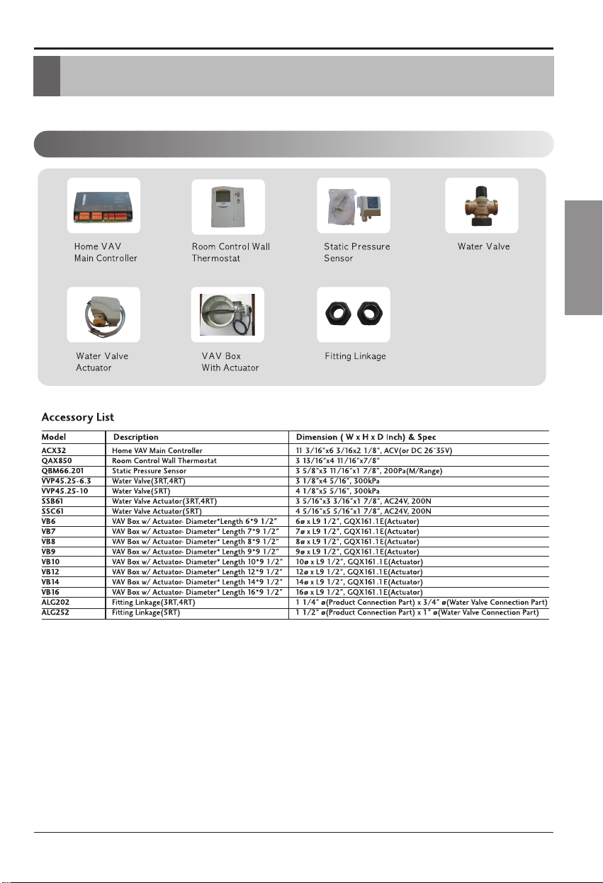
❏ Home VAV Main Controller
❏ Room Control Wall Thermostat
❏ Static Pressure Sensor
❏ Water Valve
❏ Water Valve Actuator
❏ VAV Box With Actuator
❏ Fitting Linkage
❏ Screw driver
❏ Electric drill
❏ Specified torque wrenches
❏ Spanner
❏ Ohmmeter
❏ Ammeter
❏ Thermometer
❏ Horizontal meter
❏ Pipe wrench
Installation
Requirements
Required Parts Required Tools
Page 3
ENGLISH
IMPORTANT!
Please read this instruction sheet completely before installing the product.
CAUTION
:
Safety Precautions
NOTE TO INSTALLING DEALER
: The Owners Instructions and Warranty are to be given to
the owner or prominently displayed near the indoor
Furnace/Air Handler Unit.
When wiring:
Electrical shock can cause severe personal injury or death. Only a qualified,
experienced electrician should attempt to wire this system.
When transporting:
Be careful when picking up and moving the units. Get a partner to help, and bend your knees
when lifting to reduce strain on your back. Sharp edges or thin aluminum fins on the air conditioner
can cut your finger. Move the product more than two people, Improper moving may result in injury.
When servicing
WARNING
WARNING
WATER-SOURCE HEAT PUMP
INSTALLATION INSTRUCTIONS
• Turn the power OFF at the main power box(mains) before opening the unit to check or repair
electrical parts and wiring.
• Keep your fingers and clothing away from any moving parts.
• Clean up the site after you finish, remembering to check that no metal scraps or bits of wiring have
been left inside the unit being serviced.
• Do not supply power to the unit until all wiring and tubing are completed or reconnected and checked.
• Highly dangerous electrical voltages are used in this system. Carefully refer to the wiring diagram and these
instructions when wiring. Improper connections and inadequate grounding can cause accidental injury or death.
• Ground the unit following local electrical codes.
• Connect all wiring tightly. Loose wiring may cause overheating at connection points and a possible fire hazard.
This air conditioning system meets strict safety and operating standards. As the installer or service person, it is
an important part of your job to install or service the system so it operates safely and efficiently.
• Installation or repairs made by unqualified persons can result in hazards to you and others.
Installation MUST conform with local building codes or, in the absence of local codes, with the National
Electrical Code NFPA 70/ANSI C1-1993 or current edition and Canadian Electrical Code Part1 CSA
C.22.1.
• The information contained in the manual is intended for use by a qualified service technician familiar with
safety procedures and equipped with the proper tools and test instruments.
• Failure to carefully read and follow all instructions in this manual can result in equipment malfunction,
property damage, personal injury and/or death.
• Always wear safety eye wear and work gloves when installing equipment.
• Never assume electrical power is disconnected. Check with meter and equipment.
• Keep hands out of fan areas when power is connected to equipment.
• R-410A causes frostbite burns.
• R-410A is toxic when burned.
Improper installation, adjustment, alteration, service or maintenance can void the warranty.
The weight of the condensing unit requires caution and proper handling procedures when lifting
or moving to avoid personal injury. Use care to avoid contact with sharp or pointed edges.
Installation Manual 3
Page 4
4 Water Cooled Package
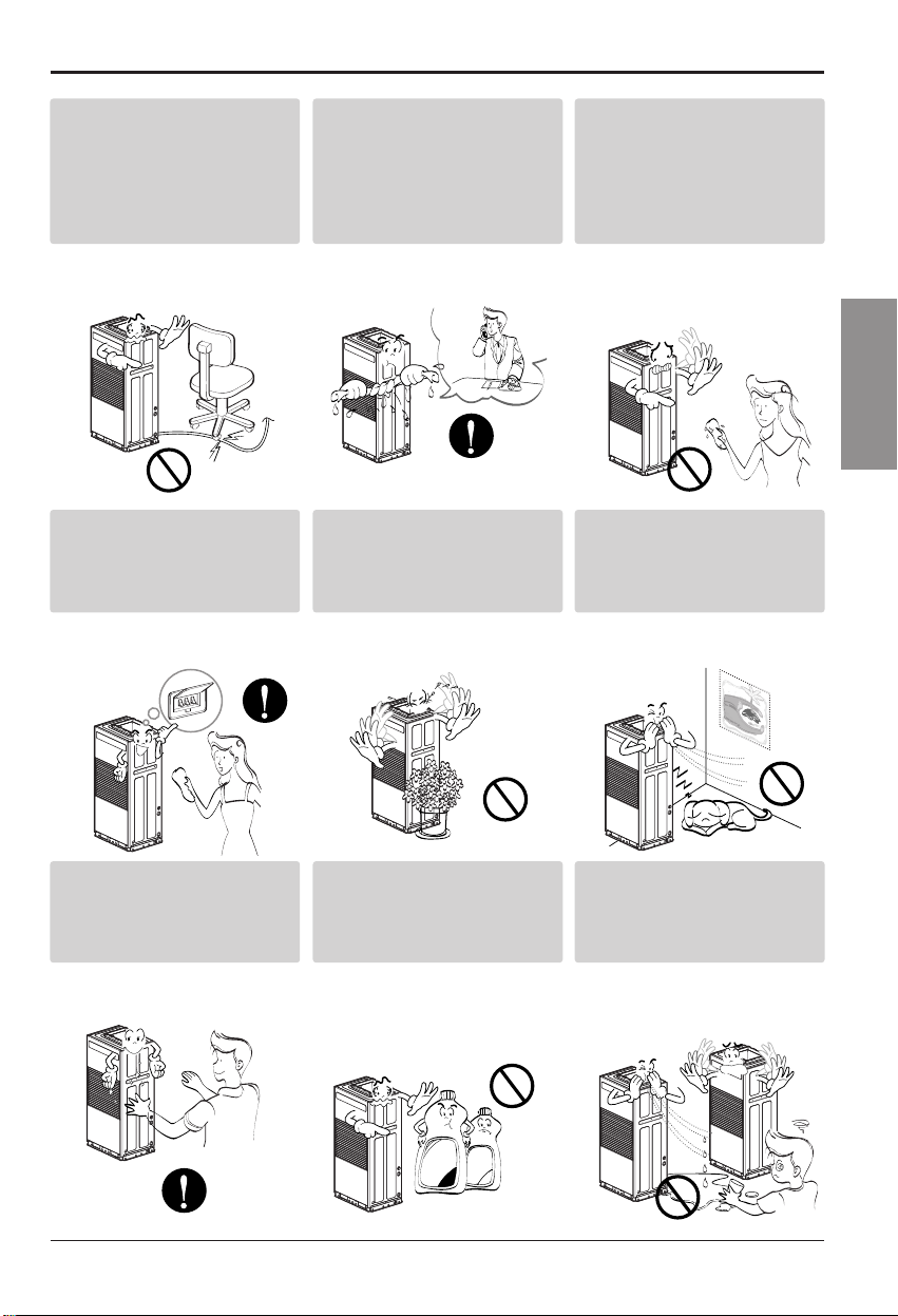
Safety Precautions
To prevent injury to the user or other people and property damage, the following instructions must
be followed.
■ Be sure to read before installing the air conditioner.
■ Be sure to observe the cautions specified here as they include important items related to safety.
■ Incorrect operation due to ignoring instruction will cause harm or damage. The seriousness is
classified by the following indications.
■ Meanings of symbols used in this manual are as shown below.
This symbol indicates the possibility of death or serious injury.
This symbol indicates the possibility of injury or damage to properties only.
■ Installation
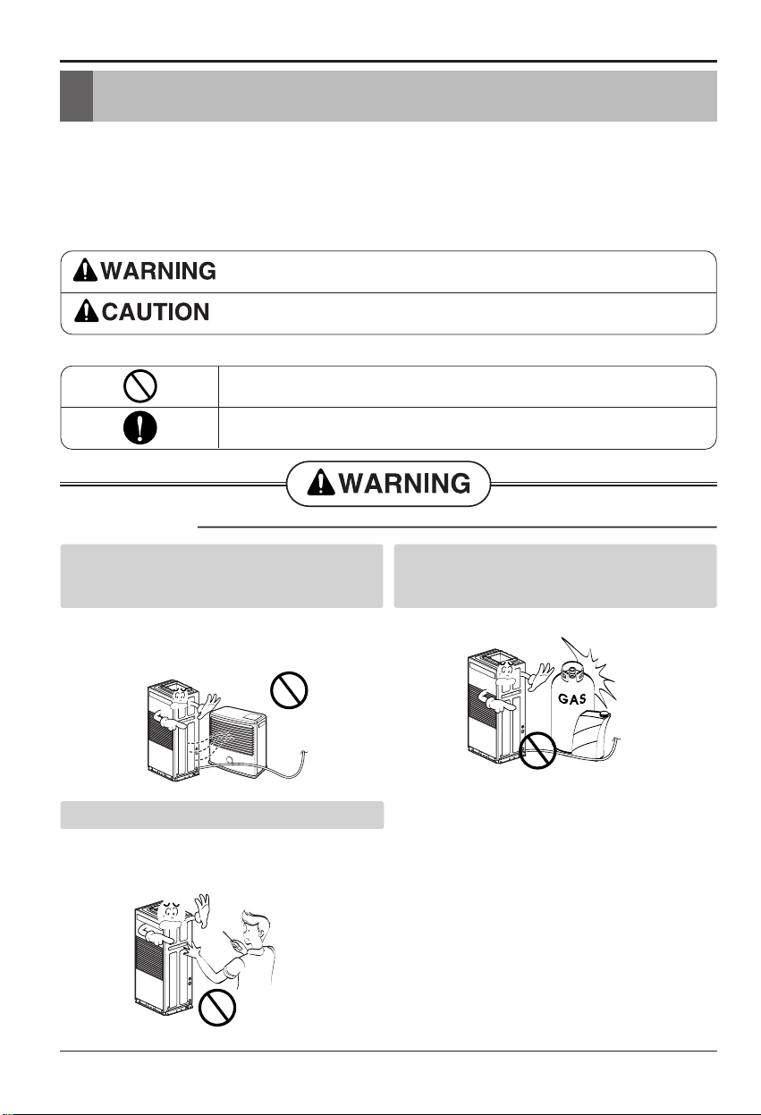
Gasolin
Do not place the power cord near a heater.
• It may cause fire and electric shock.
(See features section)
Do not use the power cord near flammable
gas or combustibles such as gasoline,
benzene, thinner, etc.
• It may cause explosion or fire.
Do not disassemble or modify products.
• It may cause failure and electric shock.
(See features section)
Be sure not to do.
Be sure to follow the instruction.
Safety Precautions
Page 5
ENGLISH
Installation Manual 5
Safety Precautions
■ Operation
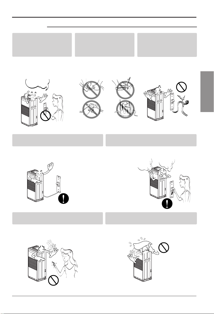
Plug in the power plug Do
not operate or stop the unit
by inserting or pulling out
the power.
• It will cause electric shock or
fire due to heat generation.
Do not damage or use an
unspecified power cord.
• It will cause electric shock or
fire.
Do not modify power cord
length.
• It will cause electric shock or
fire due to heat generation.
Always plug into a grounded outlet.
• No grounding may cause electric shock (See
Installation Manual).
Unplug the unit if strange sounds, odors, or
smoke come from it.
• Otherwise it may cause fire and electric shock
accident.
ON
Do not operate with wet hands or in damp
environment.
• It will cause electric shock.
Do not allow water to run into electric parts.
• It will cause failure of machine or electric
shock.
Page 6
6 Water Cooled Package
■ Installation
Safety Precautions
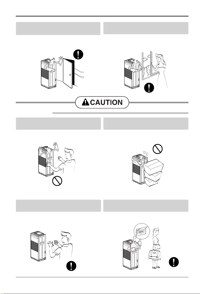
Leave the door closed while the air
conditioner is running.
• It is not designed to cool the entire house.
Ventilate before operating air conditioner
when gas goes out.
• It may cause explosion, fire, and burn.
Never touch the metal parts of the unit
when removing the filter.
• They are sharp and may cause injury.
Do not block the inlet or outlet.
• It may cause failure of appliance or accident.
Be cautious not to touch the sharp edges
when installing.
• It may cause injury.
Turn off the main power switch when not
using it for a long time.
• Prevent accidental startup and the possibility of
injury.
Page 7
ENGLISH
Installation Manual 7
Safety Precautions
Do not place heavy object
on the power cord and take
care so that the cord should
not be pressed.
• There is danger of fire or
electric shock.
If water enters the product,
turn off the the power switch
of the main body of appliance.
Contact service center after
taking the power-plug out from
the socket.
Do not clean the air
conditioner with water.
• Water may enter the unit and
degrade the insulation. It may
cause an electric shock.
Turn off the power and
breaker firstly when
cleansing the unit.
• Since the fan rotates at high
speed during operation, it may
cause injury.
Do not put a pet or house
plant where it will be
exposed to direct air flow.
• This could injure the pet or
plant.
Do not use this appliance
for special purposes such
as pets, foods, precision
machinery, or objects of art.
• It is an air conditioner, not a
precision refrigeration system.
Always insert the filter
securely.
Clean it every two weeks.
• Operation without filters will
cause failure.
Use a soft cloth to clean. Do
not use wax, thinner, or a
strong detergent.
• The appearance of the air
conditioner may deteriorate,
change color, or develop
surface flaws.
Do not drink water drained
from air conditioner. / Do
not direct airflow at room
occupants only.
• It contains containments and
will make you sick. / This
could damage your health.
Wax
Thinner
Page 8
8 Water Cooled Package
Introduction
This symbol alerts you to the risk of electric shock.
This symbol alerts you to hazards that could cause harm to the
air conditioner.
This symbol indicates special notes.
NOTICE
Introduction
Symbols Used in this Manual
Features
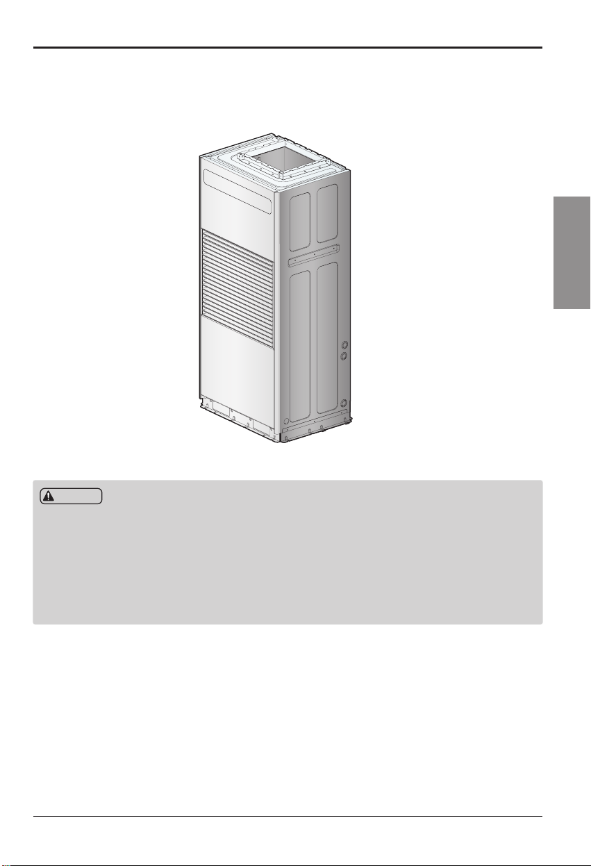
AKWW0603UA0
AKWW0483UA0
AKWW0363UA0
4.7(120)4.7(120)
4.7(120)
16.6(421.2)
4.7(120) 4.7(120) 4.7(120)
33.3(846)
31.5(800)
18.2(462)
25.1(638.3)
68.3(1735)
66.9(1700)
24.2(615)
16.0(407.4)
[Unit : inch(mm)]
1.2(30)
3.4(86.6)
12.6(320.3)5.1(129.6)
2.5(62.7)
Page 9
Installation Manual 9
ENGLISH
Installation
Installation Parts(Accessory)
Installation
Read completely, then follow step by step.
Page 10
10 Water Cooled Package
Installation
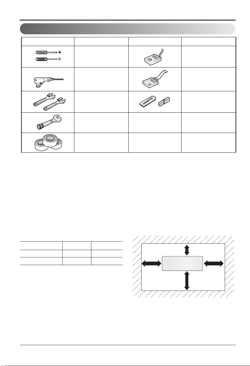
Figure FigureName
Screw driver
Electric drill
Spanner
Torque wrench
Tefron Tape
Ohmmeter
Ammeter
Thermometer,
Horizontal meter
Name
Installation Tools
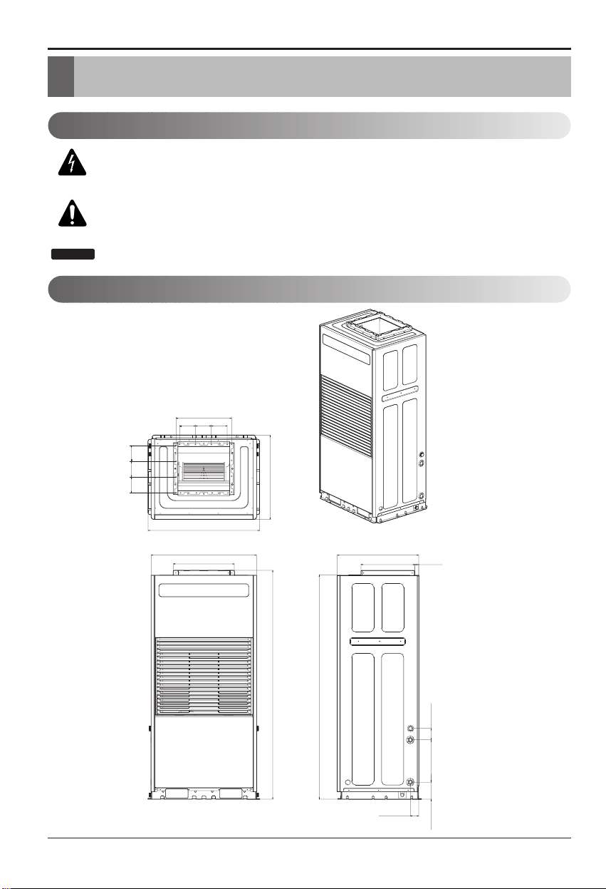
14. Installation
14.1 Space needed for installation
• For independent installation
• * Basic installation space
• Minimum space as shown in the following figure is needed depending on the piping connection type of the
product for easy installation and checking.
• If the location does not comply with this installation diagram condition, please consult with the specialized
installation center.
Pipe connection A B
Left pipe
19.7(500) 5.9(150)
Right pipe
5.9(150) 19.7(500)
[Unit: inch(mm)]
More than 100mm
More than
A
Front
More than
24.2(615)
More than
B
Page 11
Installation
Installation Manual 11
ENGLISH
14.2 Moving method and product weight
■
Because this product is a heavy object, always use a forklift for transportation and moving.
• Be careful of the following when transporting the product.
• Have more than 2 people transport the product if the weight of the product is 20Kg or more.
• PP band is for packing the product. Do not use it for transporting the product.
• Do not touch the heat exchanger fins with bear hands.You can cut your hand.
• Cut the plastic (vinyl) bag used for packaging into small pieces so that children cannot play with it. If not,
children can be suffocated while covered in the bag.
• When transporting the product with the forklift, make sure the product does not fall off.
WARNING
Page 12

12 Water Cooled Package
Installation
14.3 Basic floor construction
1. Do the basic flooring construction so that the weight of the product can be adequately supported with
concrete or similar material considering the product height.
The dimension of the basic construction should be 34" x 26" x 4"(W870 x D660 x H100) or above.
At this time, maintain the level so that the product is not tilted.
If the product is tilted, it can cause performance deterioration and noise.
2. To reduce the vibration transmission, install the floor anti-vibration pad between the basic flooring and the
product.
Recommended depth of anti-vibration pad: Min 0.8" (20mm)
[Unit:inch(mm)]
Anti-vibration pad
Basic concrete
construction
≥ 4(100)
≥ 34(870)
≥ 26(660)
Page 13

Installation Manual 13
ENGLISH
Installation
• Install the product where the weight of the outdoor unit can be sufficiently supported.
If the unit is installed at a location where the supporting strength is insufficient, the outdoor unit can fall to
injury somebody.
• Install the outdoor unit so that it does not fall even with strong wind and earthquake.
If there is a defect in the installed condition, the indoor unit can fall over to injury somebody.
• When creating the base supporter, pay special attention to the supported strength of the floor surface and
path of the pipe and wire.
• You must remove the wooden support board (MDF) and packing sheet from the base pan of the outdoor
unit before fixing the anchor bolt of the indoor unit.
The fixated condition of the outdoor unit can be unstable and could disable normal operations.
Remove before installation
Packing sheet
Wooden support board
WARNING
CAUTION
Page 14

14 Water Cooled Package
Installation
14.4 Heat source water management
• The temperature of the supplied heat source water must be maintained between 59 and 104°F. I f
not, it can cause problems to the product.
• The flux of the supplied heat source water must be controlled appropriately. If not, it can cause
abnormal noise, pipe vibration, pipe contraction or expansion depending on the temperature. For
the size of the pipe for heat source water, use the same diameter or above of the connecting pipe.
•
Refer to the following table for pipe diameter and flux of the heat source water. The higher the flux,
the higher the noise and correction due to the increased speed and higher the inflowing air bubbles.
•
Pay special attention to water quality management. If not, it can cause corrosion to the pipe of the heat
source water and cause problems to the product.(Refer to Heat source water quality management table.)
• Since the water temperature higher than 104°F can cause corrosion, it is good to add anticorrosive agent.
• Install the pipe valve, gauge and sensor where it is easy to maintain and repair. Install the heat
source water pipe valve at a low location where it can be drained if necessary.
•
Be careful not to let air get in the pipe. Air makes the flux of the heat source water unstable during
circulation and reduces the pump efficiency and cause vibration to the heat source water pipe. Therefore,
install an air purge (Air discharger) at appropriate locations where air is expected to be generated
• Adopt the following methods to prevent the pipe from freezing. If not, there is a danger of the pipe
freezing during the winter.
- When the temperature drops circulate the water with the pump before it freezes
- Operate the boiler to maintain room temperature
- When the unit is not operated for a long period of time during the winter, drain the water of the
cooling tower
- Use the anti-freeze agent
- Refer to the following table for the minimum amount of the anti-freeze agent to add
corresponding to the freezing temperature
✽ Adding the anti-freeze agent can increase the pressure drop of the heat source water system
and reduce the product performance.
• You must use the closed type cooling tower. (You cannot use the open type.)
Diameter Flux range(m/s)
≥ 4.9(125) 2.1~2.7
2~3.9(50~100) 1.2~2.1
1(25) 0.6~1.2
Minimum temperature to prevent freezing(°F)
32 23 14 5 -4 -13
Ethylene glycol (%) 0 12 20 30 - -
Propylene glycol (%) 0 17 25 33 - -
Methanol(%) 0 6 12 16 24 30
Type of anti-freeze agent
[Unit:inch(mm)]
Page 15

Installation Manual 15
ENGLISH
Installation
14.5 Heat source water quality management table
Water with a lot of alien particles can cause corrosion or create scales in the condenser and pipe to
affect the performance and life of the product. Use coolant water in accordance with [Environment
standard of Enforcement Decree of the Framework Act on Environmental Policy].
When using water other than tap water for the supplementary water in the cooling tower, you must
do a water quality test.
• The water quality management must be done for the closed water cooling type heat source water
in accordance with the following table.
• TDS (Total Dissolved Solids) among the water quality properties during the summer must be
managed to maximum of 1000mg/L and less.
If the water quality of the heat source water is not managed in accordance with the above table,
it can deteriorate the air conditioner performance and cause serious problems to the product.
Item Unit Coolant criteria
PH (25°C) 6.0 ~ 8.0
Conduction rate (25°C) (AµV/cm) 200 or less
Chlorine ion (ppm) 50 or less
Sulfuric acid ion (ppm) 50 or less
Iron (ppm) 0.3 or less
M alkalinity (ppm) 50 or less
Total hardness (ppm) 50 or less
Sulfur ion (ppm) Must not be detected
Ammonium ion (ppm) Must not be detected
Silica (ppm) 30 or less
Acetic acid ion (ppm) Not regulated
Page 16

16 Water Cooled Package
Installation
14.6 Heat source water pipe installation
•
The recommended internal water pressure for the heat source water system of this product is 1.96MPa.
• Execute the piping construction so that water drops are not formed on the outer side because it is
installed indoors.
• For the drain pipe size (1), use the same size as or larger than the pipe connecting to the product.
• Install an air purge (air discharger) in the middle of the pipe and make sure air is not generated.
• After installing the heat source water drain pipe (2), check whether the heat source water is
flowing smoothly.
• You must install a strainer (16-20 mesh) at the heat source water inlet pipe.
(When sand, trash, pieces of rust etc. are mixed into the water system, it can corrode the metallic
material or clog the heat exchanger to cause a problem.)
• In case of danger of freezing, always treat the pipe to prevent from freezing.
Do not connect the drain outlet to the heat source water outlet.
(It can cause problems to the product.)
P/T plug
Strainer
Drain valve
Heat source water
drain pipe (2)
Flexible tube
Ball valve
Flow switch
Communication line
Flange
Drain pipe (1)
connecting hole
Heat source water inlet
Heat source water outlet
Common drain pipe
CAUTION
Page 17

Installation Manual 17
ENGLISH
Installation
14.7 Heat source water pipe connection
• For the heat source water pipe (3) size, use the
same size as or larger than the pipe connecting
to the product.
• In case of danger of dew condensation, you
must install the lagging material at the heat
source water outlet pipe.
(Use polyethylene material with the thickness of
20mm for the lagging material.)
• For the connection between the heat source
water pipe and the socket, firmly tighten the
connection based on the following table.
Heat source water
pipe 3 connection hole
Heat source water outlet
Heat source water inlet
mm inch (kN) (kgf) (kN) (kgf) (N .m) (kgf .m) (Nm) (kgf .m)
12.7 1/2 3.5 350 2.5 250 20 2 35 3.5
19.05 3/4 12 1200 2.5 250 20 2 115 11.5
25.4 1 11.2 1120 4 400 45 4.5 155 15.5
31.8 1 1/4 14.5 1450 6.5 650 87.5 8.75 265 26.5
Pipe thickness
Conduction rate
Tensile stress
Bending momentum
Torque
Page 18

18 Water Cooled Package
Installation
14.8 Pipe connection order
1) Separate the cap of the coolant connection part.
2) After taking the rubber cap off the product, insert
the connecting pipe.
3) With the rubber cap covered on the pipe, execute
the pipe connecting work.
4) Reinsert the rubber cap to the product to finish
the work.
14.9 Flow switch work
•
For this product, you must install the flow switch in the unit connection return pipe system. (If you do not
install the flow switch, it will display the error information (CH 24) and the product will not be operated.)
• Select the flow switch permitted pressure specification considering the pressure specifications of
the heat source water system.
(But, you must use the one for AC 250V voltage.)
• If you do not install the flow switch and arbitrarily
operate the product, it can cause problems to the
product.
• When you operate the product when the heat source
water does not flow smoothly, it can cause problems
including damage to the heat exchanger etc.
k
Wrap Tefron tape in
screw region of pipe
CAUTION
Cover
Micro switch
Adjustment screw
Vibration plate
Bellows
1 inch or 3/4inch soc
Pad
Page 19

Installation Manual 19
ENGLISH
Installation
14.10 Flow switch installation
• Install the flow switch after checking direction of the
heat source water flow of the heat source water outlet
of the product. (Pic 1.)
• Connect the flow switch to the communication
terminal (No. 2 and 3) of the outdoor unit control box
of this product. (Pic 2~3)
(Open the flow switch cover and connect after
checking the wiring diagram. The connecting method
may be slightly different by the flow switch
manufacturer.)
• The permitted flus range for this product is 32.5~97.5
lpm
1
2
3
Pic. 1
Pic. 2
Pic. 3
Wiring diagram
COM
N.O
N.C
RANGE
COM
N.O
N.C
RANGE
Do not adjust the flux detection adjustment screw.
When the product operates within the outside of the permitted flux range with the contact points joined, it
can deteriorate the performance and cause problems.
CAUTION
Page 20

20 Water Cooled Package
Installation
14.11 Coolant piping connection
• The internal water pressure of the coolant piping system of the air conditioner is 20kg/cm2.
• For the pipe size of the coolant, use the same size as the air condition connecting pipe or wider.
(When using the cooling tower, use the pipe size of the cooling tower side.)
• The internal water pressure of the coolant piping system of the air conditioner is 20kg/cm
2
.
• For the pipe size of the coolant, use the same size as the air condition connecting pipe or wider.
(When using the cooling tower, use the pipe size of the cooling tower side.)
• Install an air drawer within the pipe and make sure cavitations don’t occur.
• The inlet/outlet pipe of the coolant must be insulated with lagging material to prevent from freezing
and icing.
• Install the valve for chemical cleaning and heat exchanger cleaning port at a location where they
are easy to operate.
• Use KS standard product for the valves.
• You must install a strainer at the coolant inlet pipe. (Use 16-20 mesh for the strainer.)
If not, it can cause problems to the product.
• When connecting the coolant pipes, always wrap Teflon tape on the screwed part. If not, it can cause
leakage to cause an accident.
CAUTION
Page 21

Installation Manual 21
ENGLISH
Installation
14.12 Condensed water piping connection
•
Install the drain pipe to be as short as possible and the inclination should be at a minimum of 1/100.
• For the size of the drain pipe, use the same size as the air condition connecting pipe or wider.
• For the drain pipe and connecting socket, you must cover them with lagging material so that icing
is not formed. Lagging material thickness: 2"(50mm)
• By using the drain trap as shown in the following diagram, make sure the drain pressure reduction
is not applied.
• Make sure you do not mistakenly mix the condensed water outlet and the coolant outlet. It can cause a
problem or an accident.
• When connecting the condensed water pipe, always wrap Teflon tape on the screwed part. If not, it can
cause a leakage to cause an accident.
Condensed water pipe
Machine room
condensed water pipe
CAUTION
2"(50mm)
Page 22

22 Water Cooled Package
Installation
14.13 Duct connection
1) By using the flexible duct (duct connecting
part), connect noise chamber connected to the
main duct within the building and the air
discharge part on top of the air conditioner so
that air does not leak. (If you do not use the
flexible duct, it can cause vibration and noise.)
2) After inserting the flexible duct between the
flange and the discharge part, tighten the
flange using the bolt.
3) Wrap lagging material on the external side of
the flexible duct (duct connecting part) to finish
with finishing tape.
(It maintains the air conditioner performance.)
Noise chamber
Flexible duct
(duct connecting part)
Flange
Flange
Flexible duct
(duct connecting part)
Insulation
material
Page 23

Installation Manual 23
ENGLISH
Installation
14.14 Main power wire connection
1) First, separate the panel on the front bottom side of the product.
Connect the power according to the electric connection diagram attached on the control box cover.
(Check whether the terminal part is connected properly.)
By using the ring type terminal, connect the main power wire to the main power terminal block and fixate
the cord clip.
2) Check whether the main power is grounded. Do not connect the grounding wire to the gas pipe, water pipe,
lightning rod or telephone grounding wire together.
3) The main power connection, circuit breaker and grounding wire assembly construction must be done in
accordance with the “Electric Facility Engineering
Standard” and “Interior Wire Regulations”.
• If the product is not grounded properly, there is a danger of electric shock.
• Grounding must be done by a qualified personnel.
Switchboard grounding
wire connection
ON
OFF
WARNING
Page 24

24 Water Cooled Package
Installation
14.15 Main power connection and facility capacity
• Consider the surrounding condition (surrounding temperature, direct sunlight, rain drops etc.)
when working on the connection.
• The thickness of the wire is the minimum thickness for metal conduction wire. Use a thicker wire of
one grade above considering the voltage drop.
• When special connection is necessary, comply with the regulation of the applicable region.
• Use standard product for power wires.
• You must always use the regulated wires so that the connecting part of the terminal does not come off by
external force. Unless the connecting part is firmly fixated, it can cause a heating to cause a fire.
• Always use an appropriate over current protection switch. Keep in mind that over-current that occurs
includes the AC current for some time.
• Some installation locations require a grounding leakage breaker to be installed. If a leakage breaker is not
installed, it can cause an electric shock.
• Use only the circuit breaker and fuse of accurate capacity. If you use a fuse, wire or copper line of
excessively large capacity, it can cause a malfunction or a fire.
WARNING
Page 25

Installation Manual 25
ENGLISH
Installation
Connect the cable
CAUTION:The power cord connected to the unit should be complied with the
following specifications.
Connect the cable to the unit by connecting the wires to the terminals on the control board
individually according to the unit connection.
The earth wire should be longer than the common wires.
The circuit diagram is not subject to change without notice.
When installing, refer to the wiring diagram behind the panel front of Unit.
CAUTION:
• The diagram is not subject to change without notice.
• Be sure to connect wires according to the wiring diagram.
• Connect the wires firmly, so that not to be pulled out easily.
• Connect the wires according to color codes by referring the wiring diagram.
RECOMMAND: Provide a circuit
breaker between power source
and the unit as shown below.
RECOMMAND:
The power cord connected to the unit should be complied with
the following specifications (ETL recognized and CSA certified).
The power connecting cable connected to the indoor and outdoor unit should be
complied with the following specifications (ETL recognized and CSA certified).
Air
Conditioner
Main power source
Circuit Breaker
Use a circuit breaker
or time delay fuse.
RECOMMAND:
When using the separate wire as the power cord, please fix the
separate wire into the control box panel by using tie wrap as the fixture.
Allowable temperature to the wire rated at least 90C°
Model
AKWW0603UA0
AKWW0483UA0
AKWW0363UA0
Min.Thickness
Main/Earth
0.020/0.020
(inch2)
AWG
6
8
10
Circuit breaker
(NFB)
45A
35A0.013/0.013
30A0.008/0.008
Leak current circuit breaker
(ELB)
45A 100mA 0.1sec
35A 100mA 0.1sec
30A 100mA 0.1sec
Line voltage (208~230V)
GN/YL
20mm
AWG18
Low voltage (below 40V)
GN/YL
20mm
Page 26

26 Water Cooled Package
Installation
14.16 Central controller communication wire connection
1) First, separate the panel on the front bottom side of the product.
2) Connect the central controller communication wire to the board on the bottom right side of the control box.
(Check whether the terminal part is connected properly.)
You must fixate the communication wire using the cord clip.
Indoor Unit PCB
Fan PCB
Inverter PCB
Main PCB
Noise filter
Main PCB
Master Controller
Page 27

Installation Manual 27
ENGLISH
Installation
14.17 Communication wire and power wire
1) Communication wire (Between Unit and VAV Master controller)
• Type: Shield wire • Diameter: 0.002 inch2(1.25mm2)
• Insulation material: PVC • Maximum permitted temperature: 60°C
• Maximum communication distance: 33"(10m) or below.
2) Remote controller wire
• Type: 3-Line cable
3) Clearance distance between communication wire and power wire
(When the power wire and the communications wire are connected in parallel, they create a
statically electric and electronic system defect that can cause a system malfunction. Ensure
50mm or more of clearance distance between the power wire of the indoor unit and
communication wire.)
Note:
1) This is the value assuming the parallel cable distance runs up to 328'(100m). When it
is over 100m, you can recalculate the value by the added distance in proportional
increments.
2) If the distortion in power wave shape continues even after maintaining the clearance
distance, increase the clearance distance.
• When putting all wires into the transmission wire or when tying all the wires to one, you must
consider the following.
- You cannot put the power wire and the communications wire in the same transmission wires.
- You cannot tie both the power wire and the communication wire together.
10A 1.2(300)
50A 2.0(500)
100A 3.9(1000)
100A more 5.9(1500)
Power wire current capacity
Clearance distance
100V or more
[Unit:inch(mm)]
Page 28

28 Water Cooled Package
Installation
14.18 Leakage checking method
• When reinstalling the product, the service that occurs from not using designated installation dealer
or the service center will be processed as paid service.
1) Pull out the suction grill.
• When you pull the top part of the suction grill lightly forward, the suction grill can be opened.
Loosen the connecting hook attached on the suction grill. Then the suction grill will be separated.
2) After pouring the water in the inner water collector of the drain pan and check
whether water is leaking.
• Pour water in the drain hole to be fully covered.
Drain hole
Page 29

Installation
Installation Manual 29
ENGLISH
3) Check whether water is drained through
the drain pipe.
If water does not come out, you must
recheck the installation condition.
• When it is impossible to check the drain pipe,
judge by whether the water in the inner water
collector is being reduced.
4) Open the valve of the pipe connected to
the coolant inlet/outlet to circulate the
water.
(Open the outlet drain pipe valve first.)
5) Check whether water is leaking in each
connecting part.
6) In case of coolant leakage
(1) Tighten the connecting part of the coolant
drain to stop the leakage.
(2) Recheck for leakage in the connecting
part or parts where leakage can occur.
(3) If there is no leakage, proceed to the next
work phase.
Outlet
Inlet
Page 30

30 Water Cooled Package
Installation
14.19 Air leakage check
1) After the air conditioner connection is
completed, run the unit in fan condition.
2) You must check for air leakage in the
flexible duct and duct connecting part.
3) In case of air leakage
(1) Tighten the connecting part of the duct to
stop the leakage.
(2) Recheck for leakage in the connecting
part or parts where leakage can occur.
(3) If there is no leakage, proceed to the next
work phase.
Flexible duct
(Duct connecting part)
Insulation
material
Page 31

Installation
Installation Manual 31
ENGLISH
14.20 Checkpoints after installation
You must read the using method through the manual to the consumer and check the following
points after installing the product.
* (Check the square box)
• Is an exclusive power circuit formed?
• Is the installation strength adequate?
• Isn’t there any leakage in the pipe?
Page 32

32 Water Cooled Package
Installation
14.21 Air leakage check
•
Is the main power wires properly inserted and fixated?
Check with the switchboard power turned off.
• Is the grounding wire properly connected?
Is the power cord properly grounded?
• Isn’t there any leakage in the coolant pipe?
Isn’t there any problem in the coolant circulation?
• You must check whether the air filter is properly
installed and whether it isn’t badly contaminated
with dust.
If the air filter is not properly installed, it cannot
filter the air flowing into indoors and can cause
problems to the air conditioner due to the
contamination.
Page 33

Installation
Installation Manual 33
ENGLISH
14.22 Test operation
You must read the using method through the manual to the consumer and check the following
points after installing the product.
* (Check the square box)
• Isn’t there any problem during central control
operation?
• Isn’t there any noise?
- The shape of the product may differ slightly
depending on the model.
• Is the air conditioning performance normal?
- Check the following details after operating the
product for 15-20 minutes.
1) Measure the temperature of the inlet and outlet.
2) Check whether the temperature difference
between the inlet and outlet is over 8°C.
Page 34

34 Water Cooled Package
Installation
• Is the product well drained?
• Isn’t there any leakage in the connecting part of
the condensed water pipe?
- The shape of the product may differ slightly
depending on the model.
Page 35

Installation Manual 35
ENGLISH
14.23 Troubleshooting during test operation
The following is the key part defects
Parts Symptom Cause Check and resolution
Compressor
External
electronic
expansion
valve
Does not operate
Stops during operation
Generates loud noise
during operation
No operation sound
even after turning the
power on
Low pressure error or
discharge error
Motor insulation broken
Strainer clogged
Insufficient lubrication
fluid
Motor insulation broken
Cross connection
Coil defect
Electronic expansion
valve clogged
Measure the resistance between the
compressor power terminal and the chassis.
Replace the strainer.
Open the drain cork and check the lubrication fluid.
Measure the resistance between the
compressor power terminal and the chassis.
Check the compressor power connection.
Check the resistance between the terminals.
EEV checking method
Discharge temperature error
If there is a problem in the system, the error code is displayed in the display window of the indoor unit.
Refer to the repair manual of service technical manual for the problem check and repair
14.24 Precaution when handing over to customer
First explain the user summary attached on the air conditioner to the customer and explain the user
manual so that it is easy to understand. (Parts directly relevant for customer safety, such as
precautions, must be explained.)
Before leaving the site, check for gas or coolant water leakage one more time and provide the
product warranty (completion confirmation, installer business card). Clean the surrounding
environment and wipe any stains that could have resulted from the installation work.
Page 36

P/No.: MFL30215311
 Loading...