

Page 1

LG Water Cooled Package
Air Conditioner
INSTALLATION MANUAL
LG
MODELS: AKWW0243AA0 AKWW0243YA0
AKWW0183AA0 AKWW0183YA0
AKWW0123AA0 AKWW0123YA0
AKWW0093AA0 AKWW0093YA0
website http://www.lgservice.com
e-mail http://www.lgeservice.com/techsup.html
IMPORTANT
• Please read this instruction sheet completely before
installing the product.
• When the power cord is damaged, replacement work shall
be performed by authorized personnel only.
• Installation work must be performed in accordance with
the national wiring standards by authorized personnel
only.
• Please retain this owner's manual for future reference after
reading it thoroughly.
ENGLISH FRANÇAIS ESPAÑOL
Page 2

2 Water Cooled Package
Single Split Wall Mounted Air Conditioner Installation Manual
TABLE OF CONTENTS
Safety Precautions............................3
Introduction ........................................8
Symbols Used in this Manual .........8
Features ...........................................8
Installation ........................................10
Installation Parts ............................10
Installation Tools ............................10
Weights / Clearance......................11
Installation ......................................13
Pre-Start-up Checklist ...................17
Maintenance ..................................18
❏ Panel, Return
❏ Grille, Discharge
❏ Hose, Flexible(1/2")
❏ Remote controller
❏ Screw driver
❏ Electric drill
❏ Specified torque wrenches
❏ Spanner
❏ Ohmmeter
❏ Ammeter
❏ Thermometer
❏ Horizontal meter
❏ Pipe wrench
Installation
Requirements
Required Parts Required Tools
Page 3

ENGLISH
IMPORTANT!
Please read this instruction sheet completely before installing the product.
CAUTION
:
Safety Precautions
NOTE TO INSTALLING DEALER
: The Owners Instructions and Warranty are to be given to
the owner or prominently displayed near the indoor
Furnace/Air Handler Unit.
When wiring:
Electrical shock can cause severe personal injury or death. Only a qualified,
experienced electrician should attempt to wire this system.
When transporting:
Be careful when picking up and moving the units. Get a partner to help, and bend your knees
when lifting to reduce strain on your back. Sharp edges or thin aluminum fins on the air conditioner
can cut your finger. Move the product more than two people, Improper moving may result in injury.
When servicing
WARNING
WARNING
WATER-SOURCE HEAT PUMP
INSTALLATION INSTRUCTIONS
• Turn the power OFF at the main power box(mains) before opening the unit to check or repair
electrical parts and wiring.
• Keep your fingers and clothing away from any moving parts.
• Clean up the site after you finish, remembering to check that no metal scraps or bits of wiring have
been left inside the unit being serviced.
• Do not supply power to the unit until all wiring and tubing are completed or reconnected and checked.
• Highly dangerous electrical voltages are used in this system. Carefully refer to the wiring diagram and these
instructions when wiring. Improper connections and inadequate grounding can cause accidental injury or death.
• Ground the unit following local electrical codes.
• Connect all wiring tightly. Loose wiring may cause overheating at connection points and a possible fire hazard.
This air conditioning system meets strict safety and operating standards. As the installer or service person, it is
an important part of your job to install or service the system so it operates safely and efficiently.
• Installation or repairs made by unqualified persons can result in hazards to you and others.
Installation MUST conform with local building codes or, in the absence of local codes, with the National
Electrical Code NFPA 70/ANSI C1-1993 or current edition and Canadian Electrical Code Part1 CSA
C.22.1.
• The information contained in the manual is intended for use by a qualified service technician familiar with
safety procedures and equipped with the proper tools and test instruments.
• Failure to carefully read and follow all instructions in this manual can result in equipment malfunction,
property damage, personal injury and/or death.
• Always wear safety eye wear and work gloves when installing equipment.
• Never assume electrical power is disconnected. Check with meter and equipment.
• Keep hands out of fan areas when power is connected to equipment.
• R-410A causes frostbite burns.
• R-410A is toxic when burned.
Improper installation, adjustment, alteration, service or maintenance can void the warranty.
The weight of the condensing unit requires caution and proper handling procedures when lifting
or moving to avoid personal injury. Use care to avoid contact with sharp or pointed edges.
Installation Manual 3
Page 4

4 Water Cooled Package
Safety Precautions
To prevent injury to the user or other people and property damage, the following instructions must
be followed.
■ Be sure to read before installing the air conditioner.
■ Be sure to observe the cautions specified here as they include important items related to safety.
■ Incorrect operation due to ignoring instruction will cause harm or damage. The seriousness is
classified by the following indications.
■ Meanings of symbols used in this manual are as shown below.
This symbol indicates the possibility of death or serious injury.
This symbol indicates the possibility of injury or damage to properties only.
■ Installation
Gasolin
Do not place the power cord near a heater.
• It may cause fire and electric shock.
(See features section)
Do not use the power cord near flammable
gas or combustibles such as gasoline,
benzene, thinner, etc.
• It may cause explosion or fire.
Do not disassemble or modify products.
• It may cause failure and electric shock.
(See features section)
Be sure not to do.
Be sure to follow the instruction.
Safety Precautions
Page 5

ENGLISH
Installation Manual 5
Safety Precautions
■ Operation
Plug in the power plug
properly.
• Otherwise, it will cause
electric shock or fire due to
heat generation or electric
shock.
Do not operate or stop the
unit by inserting or pulling
out the power plug.
• It will cause electric shock or
fire due to heat generation.
Do not damage or use an
unspecified power cord.
• It will cause electric shock or
fire.
Do not modify power cord
length.
• It will cause electric shock or
fire due to heat generation.
Always plug into a
grounded outlet.
• No grounding may cause
electric shock (See Installation
Manual).
Unplug the unit if strange
sounds, odors, or smoke
come from it.
• Otherwise it may cause fire
and electric shock accident.
ON
Do not operate with wet hands or in damp
environment.
• It will cause electric shock.
Do not allow water to run into electric parts.
• It will cause failure of machine or electric
shock.
Page 6
6 Water Cooled Package
■ Installation
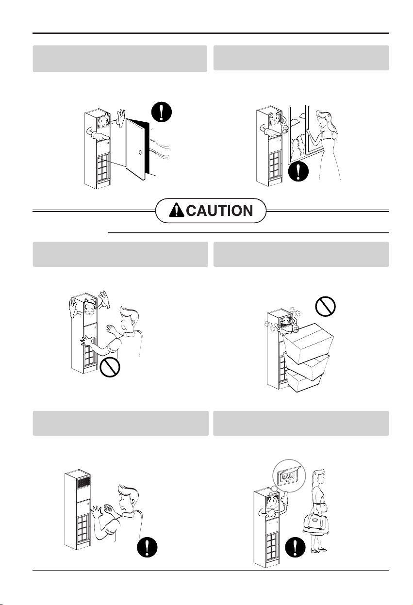
Safety Precautions
Leave the door closed while the air
conditioner is running.
• It is not designed to cool the entire house.
Ventilate before operating air conditioner
when gas goes out.
• It may cause explosion, fire, and burn.
Never touch the metal parts of the unit
when removing the filter.
• They are sharp and may cause injury.
Do not block the inlet or outlet.
• It may cause failure of appliance or accident.
Be cautious not to touch the sharp edges
when installing.
• It may cause injury.
Turn off the main power switch when not
using it for a long time.
• Prevent accidental startup and the possibility of
injury.
Page 7

ENGLISH
Installation Manual 7
Safety Precautions
Do not place heavy object
on the power cord and take
care so that the cord should
not be pressed.
• There is danger of fire or
electric shock.
If water enters the product,
turn off the the power switch
of the main body of appliance.
Contact service center after
taking the power-plug out from
the socket.
Do not clean the air
conditioner with water.
• Water may enter the unit and
degrade the insulation. It may
cause an electric shock.
Turn off the power and
breaker firstly when
cleansing the unit.
• Since the fan rotates at high
speed during operation, it may
cause injury.
Do not put a pet or house
plant where it will be
exposed to direct air flow.
• This could injure the pet or
plant.
Do not use this appliance
for special purposes such
as pets, foods, precision
machinery, or objects of art.
• It is an air conditioner, not a
precision refrigeration system.
Always insert the filter
securely.
Clean it every two weeks.
• Operation without filters will
cause failure.
Use a soft cloth to clean. Do
not use wax, thinner, or a
strong detergent.
• The appearance of the air
conditioner may deteriorate,
change color, or develop
surface flaws.
Do not drink water drained
from air conditioner. / Do
not direct airflow at room
occupants only.
• It contains containments and
will make you sick. / This
could damage your health.
Wax
Thinner
Page 8

8 Water Cooled Package
Introduction
This symbol alerts you to the risk of electric shock.
This symbol alerts you to hazards that could cause harm to the
air conditioner.
This symbol indicates special notes.
NOTICE
Introduction
Symbols Used in this Manual
Features
AKWW0243AA0 AKWW0243YA0
AKWW0183AA0 AKWW0183YA0
AKWW0123AA0 AKWW0123YA0
AKWW0093AA0 AKWW0093YA0
Page 9

ENGLISH
Installation Manual 9
CAUTION
Be cautious not to touch the sharp edges when installing It may cause
injury
Introduction
L2
L1
Page 10

10 Water Cooled Package
Introduction
1.6
AKWW0243AA0 / AKWW0183AA0 / AKWW0123AA0 / AKWW0093AA0
AKWW0243YA0 / AKWW0183YA0 / AKWW0123YA0 / AKWW0093YA0
20
20
1.6
16.7 1.6
5.1
10.2
16.7
84.7
3.7 12.6 3.7
49.45.9
35.43.2
(Unit:inch)
(Unit:inch)
18.8
17.5
49
18.3
18.7
Page 11

ENGLISH
Installation Manual 11
Installation
Hose, Flexible(2EA)
Grille, Discharge(1EA)
Remote controller (1set)
Panel, Return(1EA)
Figure FigureName
Screw driver
Electric drill
Spanner
Torque wrench
Tefron Tape
Ohmmeter
Ammeter
Thermometer,
Horizontal meter
Name
1/2" 24"
1/2" 24"
21.9
52.6
2
49.4
8.7
3.1
28.5
3.1
9.1
1.6 18.7 1.6
(Unit: inch) (Unit: inch)
18
11.8
1.8
1.7
3.93.9
4.7 8.5
❈ Recommended to use part supplied by LG ❈ Recommended to use part supplied by LG
❈ Recommended to
use part supplied by LG
❈ Not supplied by LG
Installation Parts(Option)
Installation Tools
Installation
Read completely, then follow step by step.
Page 12

12 Water Cooled Package
Installation
Weights / Clearance
- Improper Unit Lift
Test lift unit approximately 24 inches to verify proper center of gravity lift point. To avoid dropping of unit,
reposition lifting point if unit is not level. Failure to properly lift unit could result in death or serious injury or
possible equipment or property-only damage.
- Unit Location and Clearances
Locate the unit in an indoor area. The ambient temperature surrounding the unit must not be less than 45°F.
Do not locate the unit in areas subject to freezing.
Attention should be given to service clearance and technician safety.
The unit chassis should be easily removed from the cabinet in all applications.
There must be enough space for service personnel to perform maintenance or repair.
Provide sufficient room to make water, and electrical connection(s).
Local and national codes should be followed in providing electrical power connections.
See below figure for mechanical clearances.
Model Name(Cabinet) Shipping Weight(lb/kg) Unit Weight(lb/kg)
171/78 139/63
171/78 139/63
171/78 139/63
171/78 139/63
Model Name(Chassis) Shipping Weight(lb/kg) Unit Weight(lb/kg)
161/73 135/61
161/73 135/61
161/73 135/61
161/73 135/61
AKWW0243AA0
AKWW0183AA0
AKWW0123AA0
AKWW0093AA0
AKWW0243YA0
AKWW0183YA0
AKWW0123YA0
AKWW0093YA0
ALLOW 36" (914 mm)
AT UNIT FRONT FOR
CHASSIS REMOVAL
Page 13

ENGLISH
Installation Manual 13
Installation
RETURN-AIR OPENING
FLANGE ON CABINET
RETURN-AIR OPENING
FLANGE ON CABINET
2 X 4 STUD
A
B
SHEET ROCK
OPENING
TOP VIEW
SIDE VIEW
CABINET
B
2 1/4"
3 1/2"
±3/8"
3 1/2" ±3/8"
1 1/2" X 2 3/8"
FLOOR
SHEETROCK
SHEETROCK
RETURN AIR
DOOR FRAME
RETURN AIR
DOOR FRAME
1" X 1" CLOSED
CELL INSULATION
1" X 1" CLOSED
CELL INSULATION
3 1/2"
±3/8"
1 1/4"
+1/2"/-0"'
1 1/4"
+1/2"/-0"
A
1" X 1" CLOSED
CELL INSULATION
1" X 1" CLOSED
CELL INSULATION
2" X 4"
STUD
2" X 4" STUD
RETURN AIR OPENING
FLANGE ON CABINET
RETURN AIR OPENING
FLANGE ON CABINET
SHEETROCK
SHEETROCK
RETURN AIR
DOOR FLANGE
CABINET
CABINET
Finished wall and framing should not
touch the unit cabinetry.
NOTE
AB
21.3(542) 52.9(1344)
21.3(542) 52.9(1344)
21.3(542) 52.9(1344)
21.3(542) 52.9(1344)
Unit: inch(mm)
Page 14

14 Water Cooled Package
Installation
Unit Placement
Unit placement
If unit cabinet assembly includes factory provided risers, and "no" field provided between-the-floor
riser extensions, please move to Step 1.
Note: Risers are designed to accommodate a maximum of 1 1/2" to 3" expansion and contraction.
If the total calculated riser expansion exceeds 3", expansion devices must be field provided.
If unit cabinet assembly includes factory provided risers and field provided between-the floor riser
extensions are required, install the extensions before installing the cabinet.
1. Install drain valve, shut-off balancing valves, flow indicators and drain at the base of each supply
and return riser to enable system flushing at start-up, balancing and service maintenance.
2. Lift cabinet into space while aligning it into the 3"swage of the riser below.
Note: Take extra care as not to scrape or dent risers during positioning. The riser should fall
approximately 2" into the 3" swage. This will allow for the variation in floor-to-floor dimensions,
and keep the riser joints from bottoming out.
3. Level the cabinet
4. Plum bribers in two planes to as sure proper unit operation and condensate drainage.
5. Anchor all units into place.
6. For field provided risers, center the supply/return stubou is into the unit expansion slots. The
stubou is ahold be perpendicular to the cabinet panel.
7. Verify all risers are vertical and that they penetrate the swaged joint at least 1". Riser should not
be allowed to bottom out.
8. Braze riser joints. Sot solder or low-temperature alloys should not be used in this application.
9. If risers are field provided, it is recommended that the risers be anchored to the building structure
with a minimum of one contact point. For expansion and contraction reasons, do not fasten risers
rigidly to the building.
10. Seal access holes made through the cabinet for piping with suitable material to help eliminate
air leakage.
3" Swage
Floor
Stacking illustration
Floor
Page 15

ENGLISH
Installation Manual 15
Installation
Cleaning and Flushing the Water Loop
Water Connection
For vibration isolation, it is recommended that flexible steel braided hoses be in stalled instead of
hard piping between the vertical risers and the unit chassis.
Supply Grille installation
1. Install the supply grille(s) into the cabinet discharge opening. Insure there are no air gaps
between the cabinet supply air and the grille. This helps prevent recirculation of supply air into the
return air opening behind the drywall.
2. Secure grille(s) into the drywall via two screws.
Cleaning and flushing the Water Loop
After the piping system is complete, the flexible hose connector should be doubled back to
complete the water circuit external to the unit (avoiding trash settle-ut in the condenser). An extra
pipe may be necessary to connect the hose kits. See page 15 for antifreeze/water mixture by
volume.
3. Water circulation system should be filled with clean water using the water make up connections.
Note: Air vents should be opened during filling.
4. With the air vents closed, start the circulating pump and then crack the air vents to bled off the
trapped air, assuring circulation through all components of the system.
Note: Make up water must be available to the system to replace the volume formerly occupied by
the air that is bled off.
5. With the air vented and the water circulating, the entire system should be checked for leaks with
repairs made as required.
6. Operate the supplementary heat system making checks per manufacturer's instructions. During
this operation, visual checks should be made for leaks that may have occurred due to increased
heat. Repair as required.
7. Open the system at the lowest point for the initial blow down (making sure the make up water is
equal to the water being dumped). Continue blow down until the water leaving the drain runs
clear, but not less than 2 hours.
8. Shut down pumps and supplementary heat system. Reconnect the hoses placing the water-to
refrigerant heat exchanger in the water circulating system.
Note: Vents should be open when the pumps and supplementary heat system are shut down.
Flushing the water loop
Page 16

16 Water Cooled Package
Installation
Connect the cable
CAUTION:The power cord connected to the unit should be complied with the
following specifications.
Connect the cable to the unit by connecting the wires to the terminals on the control board
individually according to the unit connection.
The earth wire should be longer than the common wires.
The circuit diagram is not subject to change without notice.
When installing, refer to the wiring diagram behind the panel front of Unit.
CAUTION:
• The diagram is not subject to change without notice.
• Be sure to connect wires according to the wiring diagram.
• Connect the wires firmly, so that not to be pulled out easily.
• Connect the wires according to color codes by referring the wiring diagram.
RECOMMAND: Provide a circuit
breaker between power source
and the unit as shown below.
RECOMMAND:
The power cord connected to the unit should be complied with
the following specifications (ETL recognized and CSA certified).
The power connecting cable connected to the indoor and outdoor unit should be
complied with the following specifications (ETL recognized and CSA certified).
Air
Conditioner
Main power source
Circuit Breaker
Use a circuit breaker
or time delay fuse.
RECOMMAND:
When using the separate wire as the power cord, please fix the
separate wire into the control box panel by using tie wrap as the fixture.
Model
AKWW0243YA0
AKWW0183YA0
AKWW0123YA0
Min.Thickness
Main/Earth
0.005/0.005
(inch2)
AWG
12
12
14
14
Circuit breaker
(NFB)
25A
20A0.005/0.005
15A0.003/0.003
15A0.003/0.003AKWW0093YA0
Leak current circuit breaker
(ELB)
25A 100mmA 0.1sec
20A 100mmA 0.1sec
15A 100mmA 0.1sec
15A 100mmA 0.1sec
AKWW0123YA0
AKWW0093YA0
Line voltage (208~230V)
AWG14
GN/YL
20mm
AKWW0183YA0
AKWW0243YA0
Line voltage (208~230V)
AWG12 (Allowable temperature
to the wire rated at least 90C˚)
GN/YL
20mm
AWG18
Low voltage (below 40V)
GN/YL
20mm
Page 17

ENGLISH
Installation Manual 17
Installation
How to connect the Power cable
Remove the case of Manual controllers switch
1.Connect the power cable to the right side of manual controllers switch via clamp cord
2. Put the earth with grounding screw
3. Connect the lead wire from manual controllers switch to terminal block in control box refer to the
wiring diagram
L1
L2
Manual controllers
switch
L1 L2
Power cable
L1 L2
Earth cable
Page 18

18 Water Cooled Package
Installation
WARNING: Loose wiring may
cause the terminal to overheat or
result in unit malfunction. A fire
hazard may also exist.Therefore,
be sure all wiring is tightly
connected.
When connecting each power wire to the
corresponding terminal, follow instructions "How
to connect wiring to the terminals" and fasten
the wire tightly with the fixing screw of the
terminal plate.
How to connect wiring to the
terminals and the manual controllers
switch
For strand wiring
(1) Cut the wire end with a wire cutter or wire-
cutting pliers, then strip the insulation to
expose the strand wiring about 10mm(3/8").
(2) Using a screwdriver, remove the terminal
screw(s) on the terminal (manual controllers
switch) plate.
(3) Using a round terminal fastener or pliers,
securely clamp each stripped wire end with
a round terminal.
(4) Position the round terminal wire, and replace
and tighten the terminal screw using a
screwdriver.
Connection method of the connecting cable(Example)
High voltage
Low voltage
Strip 10mm(3/8")
Round
terminal
Connecting cable
Loosening the
terminal block
screw
Fastening the
wire tightly
Strand wire
Connecting cable
Loosening the
terminal block
screw
Fastening the
wire tightly
Page 19

ENGLISH
Installation Manual 19
Installation
How to connect the drain hose
To check the drainage.
1. Pour a glass of water on the evaporator.
2. Ensure the water flows through the drain
hose of the unit without any leakage and
goes out the drain exit.
When extending the drain hose at the unit,
install the drain pipe.
Drain piping
1. The drain hose should point downward for
easy drain flow.
2. Do not make drain piping.
main drain pipe
Drain hose
Vinyl tape
Adhesive
Downward slope
Unit drain hose
(narrow)
Water
leakage
Do not raise
Water
leakage
Accumulated
drain water
Air
Waving
Water
leakage
Tip of drain hose
dipped in water
Ditch
Less than
50mm gap
Page 20

20 Water Cooled Package
Installation
How to connect the water hose
Remove the cover of front panel
Connect supply and return water hoses refer to the label index
Water OutWater Out
Water Out
Water In
Water In
Wrench
Pipe(Water in,out)
Hose, flexible
Nut,hose
Open-end wrench (fixed)
Page 21

ENGLISH
Installation Manual 21
Installation
How to connect the remote controller lead wire
1. Remove the cover of front panel
2. Remove the cover of control box
3. Connect remote controller lead wire to the indoor PCB via hole on the control box refer to
the Wiring diagram
Conduit
Remote
controller
leadwire
L1 L2
Page 22

22 Water Cooled Package
Installation
1
Put the installation paper on the place and determine the
position and height of the fixing screws of the wired
remote controller.
• Refer to the printed side of the installation paper.
2
Plug the connecting cable into the indoor unit.
• The product is being shipped with the cable connected
only to the remote controller.
Fix the connecting cable with the cable rack.
3
Remove the installation paper before installing
the remote controller so that it can fit at the
right place.
* Do not embed the remote controller into the wall.
(It may cause the breakdown of the temperature sensor.)
* If you want to install a number of remote controller at the same place in a vertical line, install
them at regular intervals of 2cm. (It may cause the breakdown of the temperature sensor.)
* Do not install the cable with a distance of 50 m or longer. (This can cause communication
error.)
* When installing the cable, check whether the connector between the remote controller ands
the product is installed properly. The connector will not be connected when installed in
opposite sides.
Remote Controller Installation method
❏ Supply the power after connecting wired remote controller.
When you need to change wired remote controller, switch off the main power and change it.
If the wired remote controller is changed before switching off the main power, the option function
of the indoor unit can't be used. (option function like "slo" fan speed selection)
The position of the fixing screws
Main
indoor unit
CN-M CN-ZONEC
J15
C01K
IC01A
CN-DISP
LO1K
J14
CN-REMO
Red Yellow Brown
C07D
LO1D
LO2K
Side of
remote Controller
Side of
Indoor Unit
Fixing the
remote controller
Main frame
2cm
Page 23

ENGLISH
Installation Manual 23
Installation
How to install the chassis to the cabinet
1. Assemble the cover of control box
2. Assemble the chassis to the
cabinet by sliding
3. Assemble the cover of front panel
4. Assemble the filter to the front of
evaporator
5. Assemble the return panel to the
cabinet mating to hinge
Page 24

24 Water Cooled Package
Installation
Installation
- General Installation Checks
The checklist below is a summary of the steps required to successfully install a unit. This checklist is
intended to acquaint the installing personnel with procedures required in the installation process.
It does not replace the detailed instructions called out in the applicable sections of this manual.
1. Remove packaging and inspect the unit. Check the unit for shipping damage and material shortage; file a
freight claim and notify appropriate sales representation.
The unit cabinet is packaged in a cardboard.
The chassis sits inside a cardboard tray with an upper box for protection.
2. Verify the correct model, options and voltage from the unit nameplate.
3. Verify the installation location of the unit will provide the required clearance for proper operation.
4. Remove refrigeration access panel and inspect the unit. Be certain the refrigerant tubing has clearance
from adjacent parts.
- Hazardous Voltage
Disconnect all electric power, including remote disconnects and discharge all motor start/run capacitors
before servicing. Follow proper lockout/tagout procedures to ensure the power can not be inadvertently
energized. Failure to disconnect power before servicing could result in death or serious injury.The
transformer is located in the chassis control box.
- Main Electrical
1. Verify the power supply complies with the unit nameplate specifications.
2. Inspect all control panel components; tighten any loose connections.
3. Connect properly sized and protected power supply wiring to a field-supplied/installed disconnect switch
and to the unit power block in the unit's cabinet control box for equipment.
4. Install proper grounding wires to an earth ground.
All field-installed wiring must comply with NEC and applicable local codes.
- Low Voltage Wiring (AC & DC) Requirements
Connect properly sized control wiring to the proper termination points between the field supplied thermostat
and the terminal plug in the equipment's junction box.
- Field Installed Power Wiring
Power wiring to the equipment must conform to National and Local Electric Codes (NEC) by a professional
electrician.
- Live Electrical Components
During installation, testing, servicing and troubleshooting of this product, it may be necessary to work with
live electrical components. Have a qualified licensed electrician or other individual who has been properly
NOTE
NOTE
Page 25

ENGLISH
Installation Manual 25
Installation
trained in handling live electrical components perform these tasks. Failure to follow all electrical safety
precautions when exposed to live electrical components could result in death or serious injury. Verify that
the power supply available is compatible with the unit's nameplate. Use only copper conductors to connect
the power supply to the unit.
- Use Copper Conductors Only
Unit terminals are not designed to accept other types of conductors. Failure to use copper conductors may
result in equipment damage. Main Unit Power Wiring A field supplied disconnect switch must be installed at
or near the unit in accordance with the National Electric Code (NEC latest edition).
- Return Air (hinged) Acoustical Door
The hinged acoustical door is recessed into the wall so that the door is flush with the surface of the wall.
The opening through the wall for the door assembly must be centered with the return-air opening of the unit
cabinet. For full installing instructions of the return-air acoustical door.
- Drywall Installation
Before installing drywall around cabinet. Cover the cabinet supply and return openings with plastic or
cardboard to help prevent dust or construction debris from reaching unit components. Warranties will be
voided if paint or foreign debris is allowed to contaminate internal unit components. The location of the
drywall may be dependent upon the type of return air access design. Units that contain a field provided
return air access assembly, contractor must calculate location of drywall to allow for frame mounting.
- Units utilizing Hinged Acoustic Door Assembly
1. Locate the side studs a minimum of 1 1/4-inches and a maximum of 1 3/8-inches from the cabinet to the
side of the stud. This critical dimension, combined with "distance between studs" is used to determine the
side-to-side opening for the door, dimension A.The distances provided in the table are a "minimum"
dimension. Allow 3 1/2-inches from the front of the cabinet to the sheet rock surface, Top View.
2. The height of the door assembly must be positioned to recess the door 2 1/4-inches from the cabinet's
return-air opening, Side View blow-up.
3. Locate dimensions A and B for sheet rock opening size. The position of the sheet rock opening must be
centered side-to-side with the return-air opening in the cabinet. Ensure the bottom of the sheet rock
opening is 2 1/4-inches below the return-air opening in the cabinet. This allows the door recess to rest on
the bottom of the sheet rock opening for proper vertical placement of the door.
4. Place the door frame into the sheet rock opening. A positive seal is critical between the back of the door
frame and the front of the cabinet. Ensure that the gasket material seals properly.
When placing the sheet rock panel, make certain the opening for the door is centered with the return-air
opening in the cabinet (±1/8").
NOTE
Page 26

26 Water Cooled Package
Installation
- Chassis Installation
1. Connect water coil pipe to the system with a flexible steel hose assembly.
2. Verify that the shut-off/balancing valve in the return line/supply line are closed.
3. Place shut-off valves in appropriate location (see sticker on the equipment for best placement
recommendation) to allow chassis to slide easily in/out of unit cabinetry.
4. Flush system. See Cleaning and Flushing the Water Loop for flushing instructions.
5. Open the unit water valves and check piping for leaks.
6. Connect electrical to unit chassis via the quick connect mating plugs.
Four plugs are included (motor, optional condensate overflow, power and thermostat).
7. Slide chassis into the cabinet. Center the chassis left to right to minimize sound transmission.
8. Verify unit's air filter is properly place in the chassis filter rack.
9. Install cabinet's front cover to the hinged door.
10. Ensure the gasket material creates a positive seal around the entire coil to avoid coil bypass. If a field
supplied door is used, ensure the front cover is attached to the building structure and not the unit
cabinet.
- Supply Grille Installation
1. Install the supply grille(s) into the cabinet discharge opening. Insure there are no air gaps between
thecabinet supply air and the grille. This helps prevent recirculation of supply air into the return air
opening behind the drywall.
2. Secure grille(s) into the drywall via two screws.
- Cleaning and Flushing the Water Loop
1. After the piping system is complete, the flexible hose connectors should be doubled back to complete the
water circuit external to the unit (avoiding trash settle-out in the condenser). An extra pipe may be
necessary to connect the hose kits. See next page for antifreeze/water mixture by volume.
2. Water circulation system should be filled with clean water using the water make up connections.
Air vents should be opened during filling.
3. With the air vents closed, start the circulating pump and then crack the air vents to bleed off the trapped
air, assuring circulation through all components of the system.
Make up water must be available to the system to replace the volume formerly occupied by the air that is
bled off.
4. With the air vented and the water circulating, the entire system should be checked for leaks with repairs
made as required.
5. Operate the supplementary heat system making checks per manufacturer's instructions. During this
operation, visual checks should be made for leaks that may have occurred due to increased heat. Repair
as required.
6. Open the system at the lowest point for the initial blow down (making sure the make up water is equal to
the water being dumped). Continue blow down until the water leaving the drain runs clear, but not less
than 2 hours.
NOTE
NOTE
NOTE
Page 27

ENGLISH
Installation Manual 27
Installation
7. Shut down pumps and supplementary heat system. Reconnect the hoses placing the water-to-refrigerant
heat
exchanger in the water circulating system.
Vents should be open when the pumps and supplementary heat system are shut down.
- Using Antifreeze
In areas of the country where entering water temperatures drop below 45°F or where piping is being run
through areas subject to freezing, the loop must be freeze protected by using an approved antifreeze
solution to prevent loop water from freezing inside the heat exchanger. Methanol and glycols are the most
commonly used antifreeze solutions. Consult your geothermal unit supplier for locally approved solutions in
your area. Propylene glycol is not recommended in installations where the water temperature are expected
to fall below 30°F. At extreme temperatures, the viscosity increases to the point where normal loop
circulating pumps may not maintain proper flow. If propylene glycol is the only locally approved solution for
anti-freeze, good engineering practices should be used to achieve the desired flow. Calculate the
approximate volume of water in the system by using the requirements detailed in the following table, Water
Volume. Add three gallons to this total to allow for the water contained in the hose kit and geothermal unit.
Type of Antifreeze
Minimum Temperature for Freeze Protection
10°F15°F20°F25°F30°F
Methanol 25% 21% 16% 10% 3%
Propylene Glycol - - - - 6%
Before energizing the unit, the following system devices must be checked:
• Is the high voltage power supply correct and in accordance with the nameplate ratings?
• Is the field wiring and circuit protection the correct size?
• Is the low voltage control circuit wiring correct per the unit wiring diagram?
• Is the piping system clean/complete and correct? (A recommendation of all system flushing o debris from
the water-to-refrigerant heat exchanger, along with air purging from the water-to-refrigerant heat
exchanger be done in accordance with the Closed-Loop Source Heat Pump Systems Installation Guide).
• Is vibration isolation provided? (i.e. unit isolation pad, hose kits)
• Is unit serviceable? (See clearance specifications).
• Are the low/high-side pressure temperature caps secure and in place?
• Are all the unit access panels secure and in place?
• Is the thermostat in the OFF position?
• Is the water flow established and circulating through all the units?
• Is the duct work (if required) correctly sized, run, taped, insulated and weather proofed with proper unit
arrangement?
• Is the condensate line properly sized, run, trapped and pitched?
• Does the indoor blower turn freely without rubbing?
• Has all work been done in accordance with applicable local and national codes?
• Has heat transfer fluid been added in the proper mix to prevent freezing in closed system application?
• Have the chassis isolation rails been released?
• Is there a good seal between the front air panel and the coil?
Pre-Start-up Checklist
NOTE
Page 28

28 Water Cooled Package
Installation
Maintenance
- Preventive Maintenance
Maintenance on the unit is simplified with the following preventive suggestions: Filter maintenance must be
performed to assure proper operation of the equipment. Filters should be inspected at least every three
months, and replaced when it is evident they are dirty.
Check the contactors and relays within the control panel at least once a year. It is good practice to check
the tightness of the various wiring connections within the control panel. A strainer (60 mesh or greater) must
be used on an open loop system to keep debris from entering the unit heat exchanger and to ensure a
clean system. For units on well water, it is important to check the cleanliness of the water-to-refrigerant heat
exchanger. Should it become contaminated with dirt and scaling as a result of bad water, the heat
exchanger will have to be back flushed and cleaned with a chemical that will remove the scale. This service
should be performed by an experienced service person.
- Hazardous Chemicals
Coil cleaning agents can be either acidic or highly alkaline. Handle chemical carefully. Proper handling
should include goggles or face shield, chemical resistant gloves, boots, apron or suit as required. For
personal safety, refer to the cleaning agent manufacturers Materials Safety Data Sheet and follow all
recommended safe handling practices. Failure to follow all safety instructions could result in death or serious
injury. It should be noted that the water quality should be checked periodically. See the following water
quality table.
Scaling Calcium and magnesium(total hardness) Less than 350 ppm
pH 7 ~ 9.5
Hydrogen Sulfide Less than 1 ppm
Corrosion
Sulfates Less than 25 ppm
Chlorides Less than 125 ppm
Carbon Dioxide Less than 75 ppm
Total dissolved solids(TDS) Less than 1000 ppm
Biological Growth Iron Bacteria Low
Erosion Suspended Solids Low
Cooling Heating
Air 64.4~89.6 50~69.8
Water 59~104 59~104
Operating range (unit : Fahrenheit, °F)
Page 29

P/No.: MFL30215306
 Loading...