

LG AK-W300LC00 installation manual

INSTALLATION MANUAL
SINGLE PACKAGE TYPE AIR CONDITIONER
AIR
CONDITIONER
Please read this installation manual completely before installing the product.
Installation work must be performed in accordance with the national wiring
standards by authorized personnel only.
Please retain this installation manual for future reference after reading it
thoroughly.
www.lg.com
Copyright © 2019 - 2021 LG Electronics Inc. All Rights Reserved.
MFL67445824
Rev.05_040621
ENGLISH
FRANÇAIS

TIPS FOR SAVING ENERGY
2
ENGLISH
TIPS FOR SAVING ENERGY
Here are some tips that will help you minimize the power consumption when you use the air
conditioner. You can use your air conditioner more efficiently by referring to the instructions
below:
• Do not cool excessively indoors. This may be harmful for your health and may consume more
electricity.
• Block sunlight with blinds or curtains while you are operating the air conditioner.
• Keep doors or windows closed tightly while you are operating the air conditioner.
• Adjust the direction of the air flow vertically or horizontally to circulate indoor air.
• Speed up the fan to cool or warm indoor air quickly, in a short period of time.
• Open windows regularly for ventilation as the indoor air quality may deteriorate if the air
conditioner is used for many hours.
• Clean the air filter once every 2 weeks. Dust and impurities collected in the air filter may block the
air flow or weaken the cooling / dehumidifying functions.
For your records
Staple your receipt to this page in case you need it to prove the date of purchase or for warranty
purposes. Write the model number and the serial number here:
Model number :
Serial number :
You can find them on a label on the side of each unit.
Dealer’s name :
Date of purchase :
SAFETY INSTRUCTIONS
3
SAFETY INSTRUCTIONS
The following safety guidelines are intended to prevent unforeseen risks or damage from unsafe or
incorrect operation of the appliance.
The guidelines are separated into ‘WARNING’ and ‘CAUTION’ as described below.
This symbol is displayed to indicate matters and operations that can cause risk.
!
Read the part with this symbol carefully and follow the instructions in order to avoid risk.
WARNING
!
This indicates that the failure to follow the instructions can cause serious injury or death.
CAUTION
!
This indicates that the failure to follow the instructions can cause the minor injury or damage to
the product.
WARNING
!
• Installation or repairs made by unqualified persons can result in hazards to you and others.
• Installation shall be in accordance with national standards of electrical appliances.
• The information contained in the manual is intended for use by a qualified service technician
familiar with safety procedures and equipped with the proper tools and test instruments.
• Failure to carefully read and follow all instructions in this manual can result in equipment
malfunction, property damage, personal injury and/or death.
ENGLISH
Installation
• Do not use a defective or underrated circuit breaker. Use this appliance on a dedicated circuit.
- There is risk of fire or electric shock.
• For electrical work, contact the dealer, seller, a qualified electrician, or an Authorized Service Center.
- Do not disassemble or repair the product. There is risk of fire or electric shock.
• Always ground the product.
- There is risk of fire or electric shock.
• Install the panel and the cover of control box securely.
- There is risk of fire or electric shock.
• Always install a dedicated circuit and circuit breaker.
- Improper wiring or installation may cause fire or electric shock
• Use the correctly rated circuit breaker or fuse.
- There is risk of fire or electric shock.
• Use the specified wires to connect the unit.
- There is risk of fire or electric shock.
• Do not install, remove, or re-install the unit by yourself (customer).
- There is risk of fire, electric shock, explosion, or injury.
• Be cautious when unpacking and installing the product.
- Sharp edges could cause injury. Be especially careful of the case edges and the fins on the
condenser and evaporator.
• For installation, always contact the dealer or an Authorized Service Center.
• Do not install the product on a defective installation stand.
- It may cause injury, accident, or damage to the product.

4
ENGLISH
Operation
SAFETY INSTRUCTIONS
• Be sure the installation area does not deteriorate with age.
- If the base collapses, the air conditioner could fall with it, causing property damage, product failure,
and personal injury.
• Use a vacuum pump or Inert (nitrogen) gas when doing leakage test or air purge. Do not compress
air or Oxygen and Do not use Flammable gases. Otherwise, it may cause fire or explosion.
- There is the risk of death, injury, fire or explosion.
• When using Thermostat, be sure to use double insulated thermostat.
• Take care to ensure that power cable could not be pulled out or damaged during operation.
- There is risk of fire or electric shock.
• Do not place anything on the power cable.
- There is risk of fire or electric shock.
• Do not touch(operate) the product with wet hands.
- There is risk of fire or electrical shock.
• Do not place a heater or other appliances near the power cable.
- There is risk of fire and electric shock.
• Do not allow water to run into electric parts.
- It may cause failure of the product or electric shock.
• Do not store or use flammable gas or combustibles near the product.
- There is risk of fire or failure of product.
• Do not use the product in a tightly closed space for a long time.
- Oxygen deficiency could occur.
• When flammable gas leaks, turn off the gas and open a window for ventilation before turn the
product on.
- Do not use the telephone or turn switches on or off. There is risk of explosion or fire
• If strange sounds, smell or smoke comes from product. Turn the circuit breaker off or disconnect
the power supply cable.
- There is risk of electric shock or fire.
• Stop operation and close the window in storm or hurricane. If possible, remove the product from the
window before the hurricane arrives.
- There is risk of property damage, failure of product, or electric shock.
• Do not open the panel of product during operation. (If the unit has the electrostatic filter, Do not
touch it.)
- There is risk of physical injury, electric shock, or product failure.
• When the product is soaked (flooded or submerged), contact an Authorized Service Center.
- There is risk of fire or electric shock.
• Be cautious that water could not enter the product.
- There is risk of fire, electric shock, or product damage.
• Ventilate the product from time to time when operating it together with a stove, etc.
- There is risk of fire or electric shock.
• Turn the main power off when cleaning or maintaining the product.
- There is risk of electric shock.
• When the product is not be used for a long time, turn off the circuit breaker.
- There is risk of product damage or failure, or unintended operation.
• Take care to ensure that nobody could step on or fall onto the unit.
- This could result in personal injury and product damage.

SAFETY INSTRUCTIONS
CAUTION
!
Installation
• Always check for gas (refrigerant) pressure after installation or repair of product.
- Low refrigerant levels may cause failure of product.
• Install the drain hose to ensure that water is drained away properly.
- A bad connection may cause water leakage.
• Keep level even when installing the product.
- To avoid vibration or water leakage.
• Do not install the product where the noise or hot air from the outdoor unit could damage the
neighborhoods.
- It may cause a problem for your neighbors.
• Don't use people to lift and transport the product.
- Avoid personal injury.
• Do not install the product where it will be exposed to sea wind (salt spray) directly.
- It may cause corrosion on the product. Corrosion, particularly on the condenser and evaporator
fins, could cause product malfunction or inefficient operation.
• Do not let the air conditioner run for a long time when the humidity is very high and a door or a
window is left open.
- Moisture may condense and wet or damage furniture.
Operation
• Do not expose the skin directly to cool air for long periods of time. (Don't sit in the draft.)
- This could harm to your health.
• Do not use the product for special purposes, such as preserving foods, works of art, etc. It is a
consumer air conditioner, not a precision refrigeration system.
- There is risk of damage or loss of property.
• Turn on the power at least 6 hours before starting operation.
- Starting operation immediately after turning on the main power switch can result in severe damage
to internal parts. Keep the power switch turned on during the operational season.
5
ENGLISH

TABLE OF CONTENTS
6
ENGLISH
TABLE OF CONTENTS
2 TIPS FOR SAVING ENERGY
3 SAFETY INSTRUCTIONS
7 INTRODUCTION
7 Features
8 DIMENSIONAL DATA
9 INSTALLATION OF UNIT
9 Inspection
9 Location and Recommendations
10 Ductwork
10 Change Airflow
11 Condensate Drain Piping
11 2 Inch filter Installation
11 2 Inch filter installation guide
12 2 Inch filter removal guide
13 Installation of Remote Controller(Accessory)
17 Electronic Wiring
18 Field Wiring
20 Connect the cable to the Product
22 DIP Switch Setting in Indoor Main PCB
22 Group Control
23 INSTALLER SETTING
23 How to enter installer setting
24 ESP setting
25 Test run setting
26 Self-Diagnosis Function
31 Starting the Unit
32 Final Installation Checklist and Maintenance
34 Installation guide at the seaside
INTRODUCTION
Features
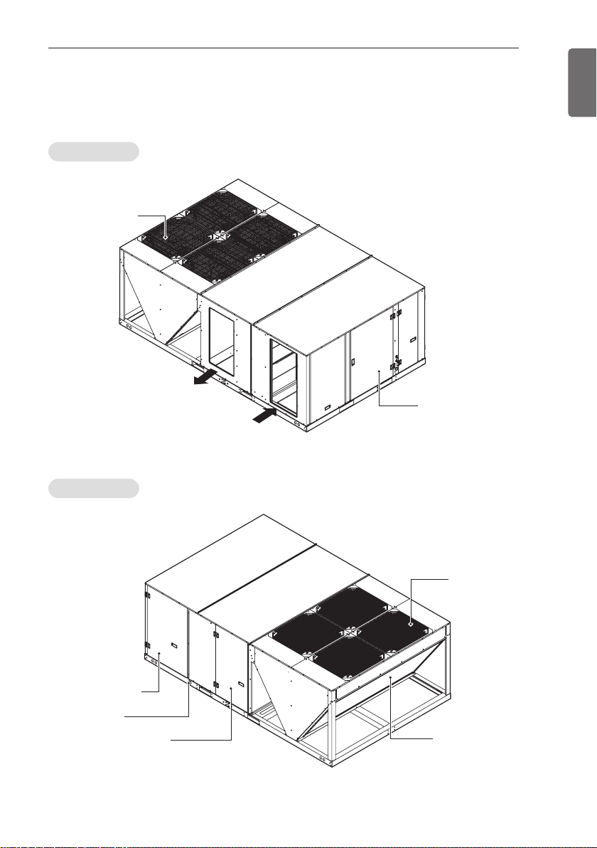
Front View
Air outlet
vents
INTRODUCTION
7
ENGLISH
Rear View
Compressor
Access panel
Drain Hole
Motor Access Panel
Supply Air
Control
access panel
Return Air
Air outlet
vents
Air intake
vents
DIMENSIONAL DATA
More than
1 160(45-11/16)
More than
860(33-7/8)
More than 860(33-7/8)
More than 1 160(45-11/16)
E
F
G
C
A
B
D
H
B
H
G
H
C
D
RETURNRETURN
SUPPLYSUPPLY
RETURN
SUPPLY
A
FE
Drain Hole
More than 1 160(45-11/16)
More than 1 160(45-11/16)
More than 860(33-7/8)
More than 860(33-7/8)
B
C
D
A
8
ENGLISH
DIMENSIONAL DATA
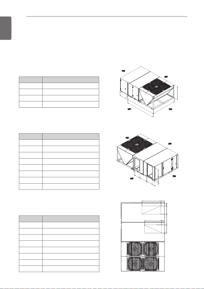
Single packaged Units are designed for outdoor mounting with vertical condenser discharge.
They can be located either at ground level or on roof.
Each unit contains an operating charge of Refrigerant as shipped.
Product Dimensions (Figure 1A)
[Unit : mm (inch)]
Tool KE
A 1 242(48-29/32)
B 2 230(87-25/32)
C 3 520(138-19/32)
D 2 673(105-6/25)
Horizontal Flow Application
(Figure 1B)
Tool KE
A 460(18-1/8)
B 684(26-7/8)
C 506(19-15/16)
D 173(6-3/4)
E 142(5-5/8)
F 1 033(40-11/16)
G 213(8-7/16)
H 899(35-7/16)
Down Flow Application (Figure 1C)
Tool KE
A 460(18-1/8)
B 724(28-9/16)
C 506(19-15/16)
D 142(5-10/16)
E 110(4-3/8)
F 1 033(40-11/16)
G 97(3-7/8)
H 899(35-7/16)
[Unit : mm (inch)]
Figure 1A [Unit : mm (inch)]
Figure 1B [Unit : mm (inch)]
[Unit : mm (inch)]
Figure 1C [Unit : mm (inch)]
INSTALLATION OF UNIT
INSTALLATION OF UNIT
9
ENGLISH
Inspection
1 Check for damage after unit is unloaded.
Report promptly, to the carrier, any
damage found to unit. Do not drop unit.
2 Check the unit nameplate to determine if
the unit voltage is correct for the
application. Determine if adequate
electrical power is available. Refer to the
application specifications.
3 Check to be sure the refrigerant charge
has been retained during shipment.
Access to 1/4" flare pressure taps may be
gained by removing compressor
compartment access panel.
Location and Recommendations
Unit Support
If unit is to be roof mounted check building
codes for weight distribution requirements.
Location and Clearances
Installation of unit should conform to local
building codes and the National Electrical Code.
Select a location that will permit unobstructed
airflow into the condenser coil and away from
the fan discharge and permit unobstructed
service access into the compressor
compartment. Suggested airflow clearances and
service clearances are given in Figure 1.
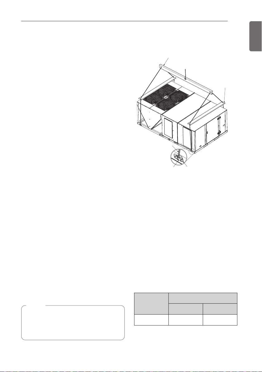
Placing and Rigging
Rig the unit using either belt or cable slings.
The sling eyelet must be placed through the
lifting holes in the base rail of the unit. The
point where the slings meet the lifting eyelet
should be at least 1.8 m above the unit. Use
spreader bars to prevent excessive pressure
on the top of the unit during lifting.
NOTE
• The use of "spreader bars" is required
when hoisting the unit (prevents
damage to sides and top). Top crating
can be used as spreader bars.
Lifting Beam
Cable or Chain
Clevis
Recommended
Rigging Method
Holes in Base
Rail
Spreader
Bar
Figure 2
Roof Mounted Unit
On new roofs, the curb should be welded
directly to the roof deck. For existing
construction, nailers must be installed under
the curb if welding is not possible. Be sure
attach the down flow ductwork to the curb
before setting unit in place.
When installing the unit, it must be level to
insure proper condensate flow from the unit
drain pan.
Slab Mount
"For ground level installation, the unit base
should be adequately supported and hold the
unit near level. The installation must meet the
guidelines set forth in local codes."
Chassis
KE 915 2 017
Net Weight
kg lbs
10
ENGLISH
INSTALLATION OF UNIT
Ductwork
Ductwork construction guidelines
Connections to the unit should be made with
76 mm(3’) canvas connectors to minimize
noise and vibration transmission.
Elbows with turning vanes or splitters are
recommended to minimize air noise and
resistance.
The first elbow in the ductwork leaving the
unit should be no closer than three times
blower diameter to avoid turbulence and back
pressure.
Attaching Horizontal Ductwork to
the Unit
All conditioned air ductwork should be
insulated to minimize heating and cooling duct
losses. Use minimum of 50 mm(2’) of
insulation with a vapor barrier. The outside
ductwork must be weather proofed between
the unit and the building.
When attaching ductwork to a horizontal unit,
provide a flexible water tight connection to
prevent noise transmission from the unit to
the ducts. The flexible connection must be
indoors and molded out of heavy canvas.
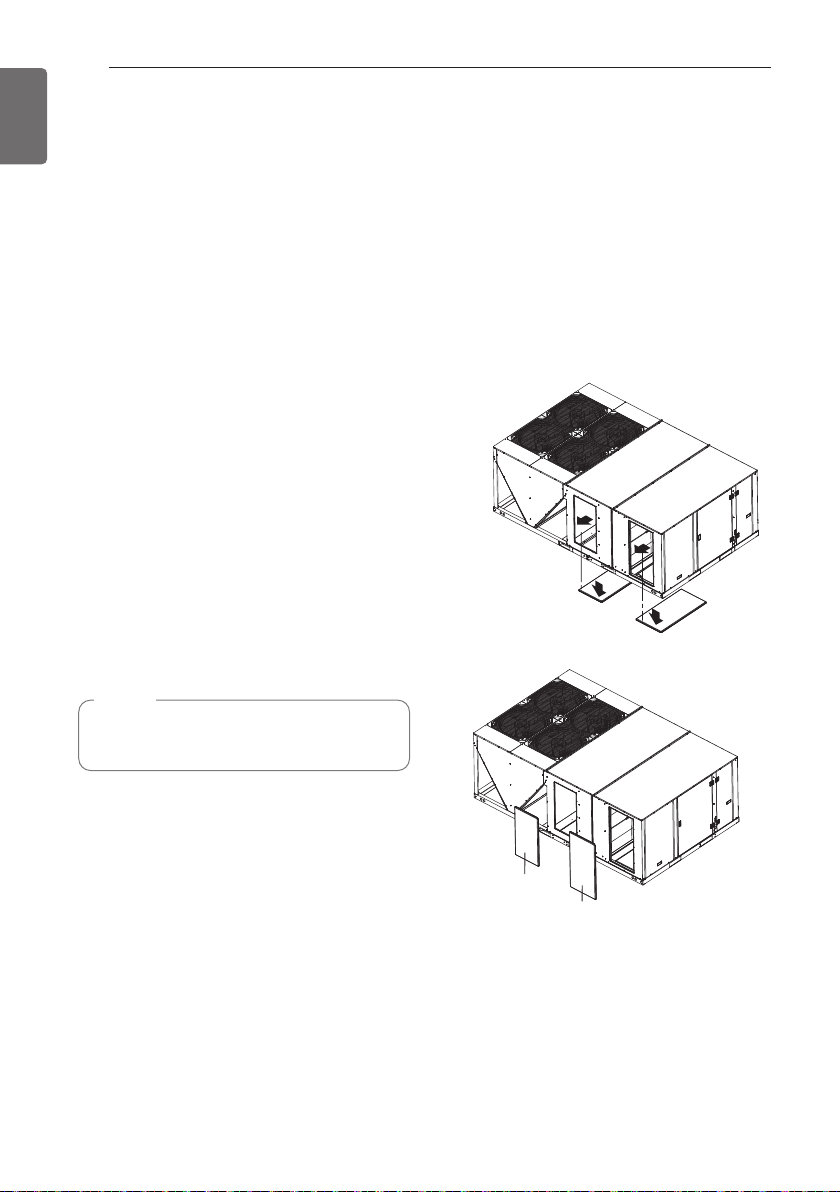
Change Airflow
Horizontal flow to Down flow Conversion
1 Remove the covers from the down flow
openings on the base panel by unscrewing
as shown.
2 Close the horizontal Supply and Return
openings on the front panel by attaching
the covers firmly on to it which are
removed from the down flow openings.
* Cover assembly should be assembled as
insulation being downward.
(1)
(2)
NOTE
• Do not draw the canvas taut between
the solid ducts.
Supply
cover
Return
cover
Figure 3
INSTALLATION OF UNIT
Side panel
Side panel
11
ENGLISH
Condensate Drain Piping
A 1 inch female condensate drain connection
is located on the corner of the unit next to the
motor access panel. A trap should be installed
and filled with water before starting the unit to
avoid air from being drawn through. Follow
local codes and standard piping practices
when running the drain line. Pitch the line
downward, away from the unit, and avoid long
horizontal runs. See Figure 4.
Do not use reducing fittings in the drain lines.
The condensate drain must be:
1 Made of 25.4 mm(1") pipe size.(NPT)
2 For 6.35 mm per 30.48 cm(Pitched 1/4" per
foot) to provide free drainage to
convenient drain system.
3 Trapped
4 Must not be connected to closed drain
system.
Panel Enclosure
25.4 mm(1”) Female (NPT)
Static pressure
Drain Pan
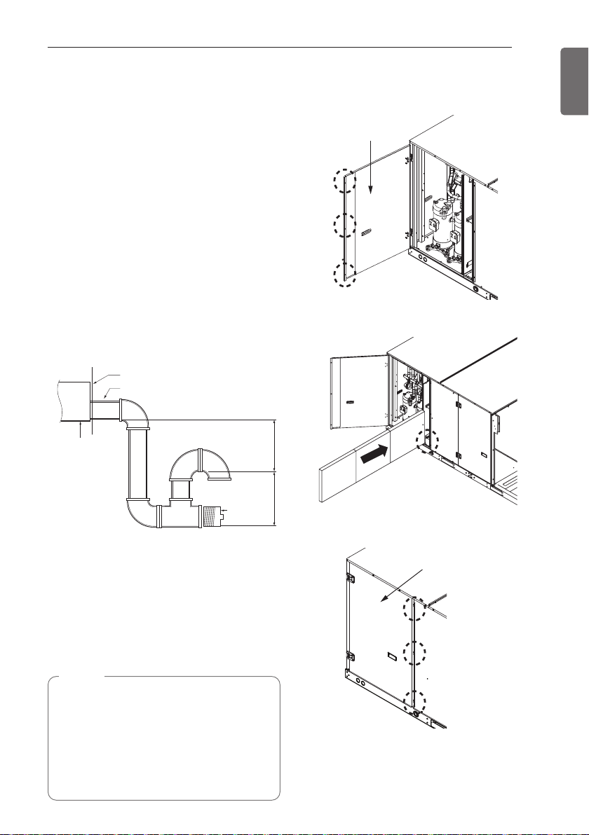
2 Inch filter installation guide
1 Loosen the screws to open the side panel.
2 Place the 2 inch filter on the upper and
lower bracket and push it in.
76.2 mm(3”) minimum
2 Inch filter Installation
h The pre-filter is provided by default, and
water cleaning is possible.
h Pre-filter and 2-inch filter can be removed
and inserted by opening the side panel of
the product.
(Refer to the 2 inch filter installation guide)
NOTE
• Do not operate unit without filters in place.
• Only pre-filter is washable type.
• The 2-inch filter is not provided as default,
• The prefilter and 2 inch filter can be
please purchase and use it locally.
installed together.
Cleanout
Plug
Figure 4
76.2 mm(3”) minimum
3 Close the side panel and combine with the
screws.
h 7.5 ~ 25RT install 2 inch filter in order of
1, 2, 3
 Loading...