

Page 1
Page 2
Page 3
Page 4
Page 5
Page 6
Page 7
Page 8
Page 9
Page 10
Page 11
Page 12
Page 13
Page 14
Page 15
Page 16
Page 17
Page 18
Page 19
Page 20
Page 21
Page 22
Page 23
Page 24
Page 25
Page 26
Page 27
Page 28
Page 29

Page 30

Page 31

Page 32

Page 33

Page 34

Page 35

Page 36

Page 37

Page 38

Page 39

Page 40

Page 41

Page 42

Page 43

Page 44

Page 45

Page 46

Page 47

Page 48

Page 49

Page 50

Page 51

Page 52

Page 53

Page 54

Page 55

Page 56

Page 57

Page 58

Page 59

Page 60

Page 61

Page 62

Page 63

Page 64

Page 65

Page 66

Page 67

Page 68

LG AIR CONDITIONER ERROR CODES
LG Air Conditioner Error = Lights Flashing
-Switch off the circuit breaker in your AC unit and then switch it on again.
-If there is no loose connection your air conditioner will start its operations normally.
-Check wiring connections for any loose connection on the unit.
-A low refrigerant charge can cause the air conditioner light to blink.
LG Split System Air Conditioner Error code = C5 or CH05
LG AC Fault Definition = Communication between indoor and outdoor units
Flashing Light = 5
Display = Indoor Outdoor
Indoor Operation = OFF
LG Split System Air Conditioner Error code = CA or CH10
LG AC Fault Definition = Discharge temp more than 130 °C – Faulty discharge thermistor
Flashing Light = 10
Display = Indoor Outdoor
Indoor Operation = ON
LG Split System Air Conditioner Error code = C1 or CH01
LG AC Fault Definition = Indoor temperature sensor open or closed circuit
Light Will Flash = 1
Display = Indoor
Indoor Operation = ON
LG Split System Air Conditioner Error code = C2 or CH02
LG AC Fault Definition = Outdoor temperature sensor open or closed circuit – Outdoor air or
piping temperature thermistor error
(Measured the resistance of the two thermistors)
Flashing Light = 2
Display = Indoor Outdoor
Indoor Operation = ON
LG Split System Air Conditioner Error code = C3 or CH03
LG AC Fault Definition = Communication (Indoor Wired R/Control) Data Communication Fault
Flashing Light = 3
LG Split System Air Conditioner Error code = C4 or CH04
LG AC Fault Definition = Heat-sink temperature sensor open or closed circuit
Flashing Light = 4
Display = Indoor Outdoor
Indoor Operation = ON
Page 69

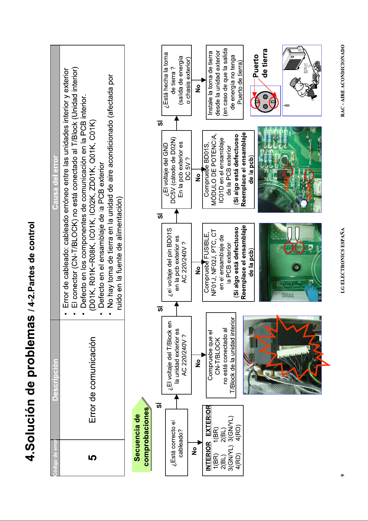
LG Split System Air Conditioner Error code = C5 or CH05
LG AC Fault Definition = Communication between indoor and outdoor units
Flashing Light = 5
Display = Indoor Outdoor
Indoor Operation = OFF
LG Split System Air Conditioner Error code = C6 or CH06
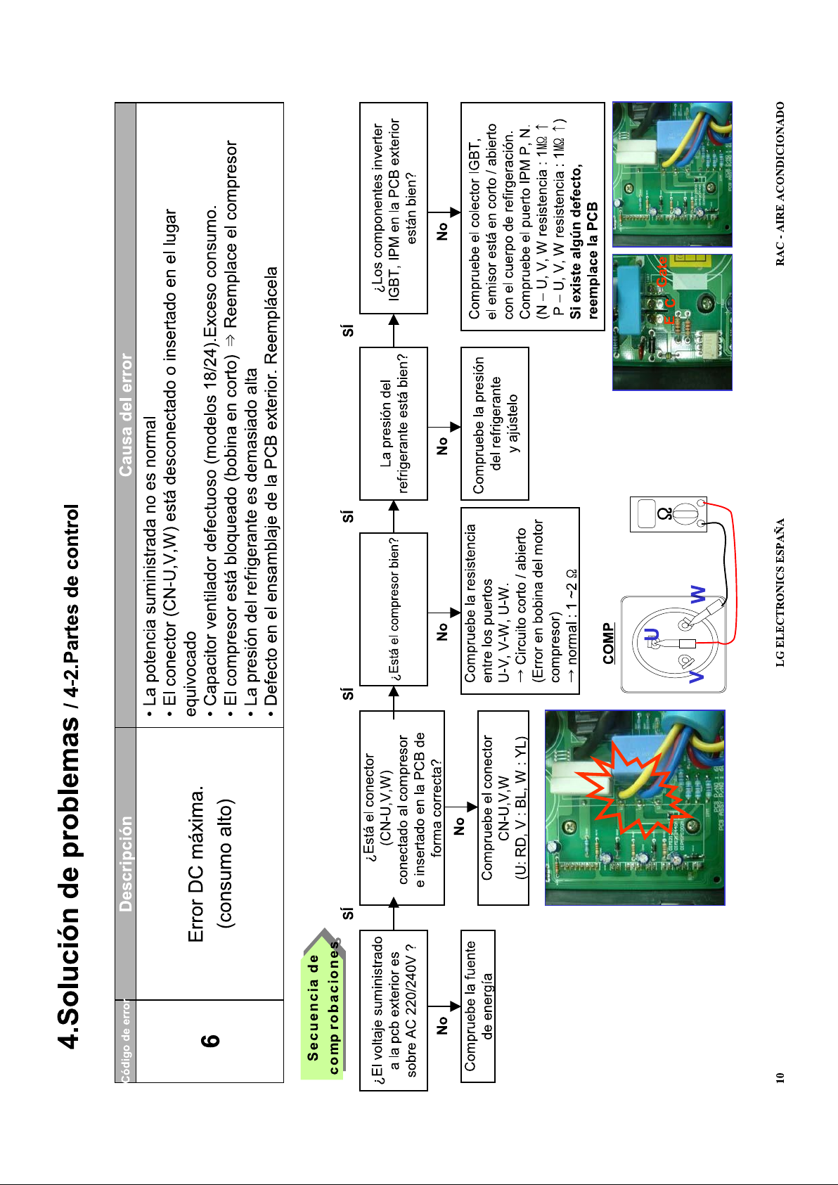
LG AC Fault Definition = Excessive current at inverter DC power circuit – DC Peak Power
Flashing Light = 6
Display = Indoor Outdoor
Indoor Operation = SHUTDOWN
LG Split System Air Conditioner Error code = C7 or CH07
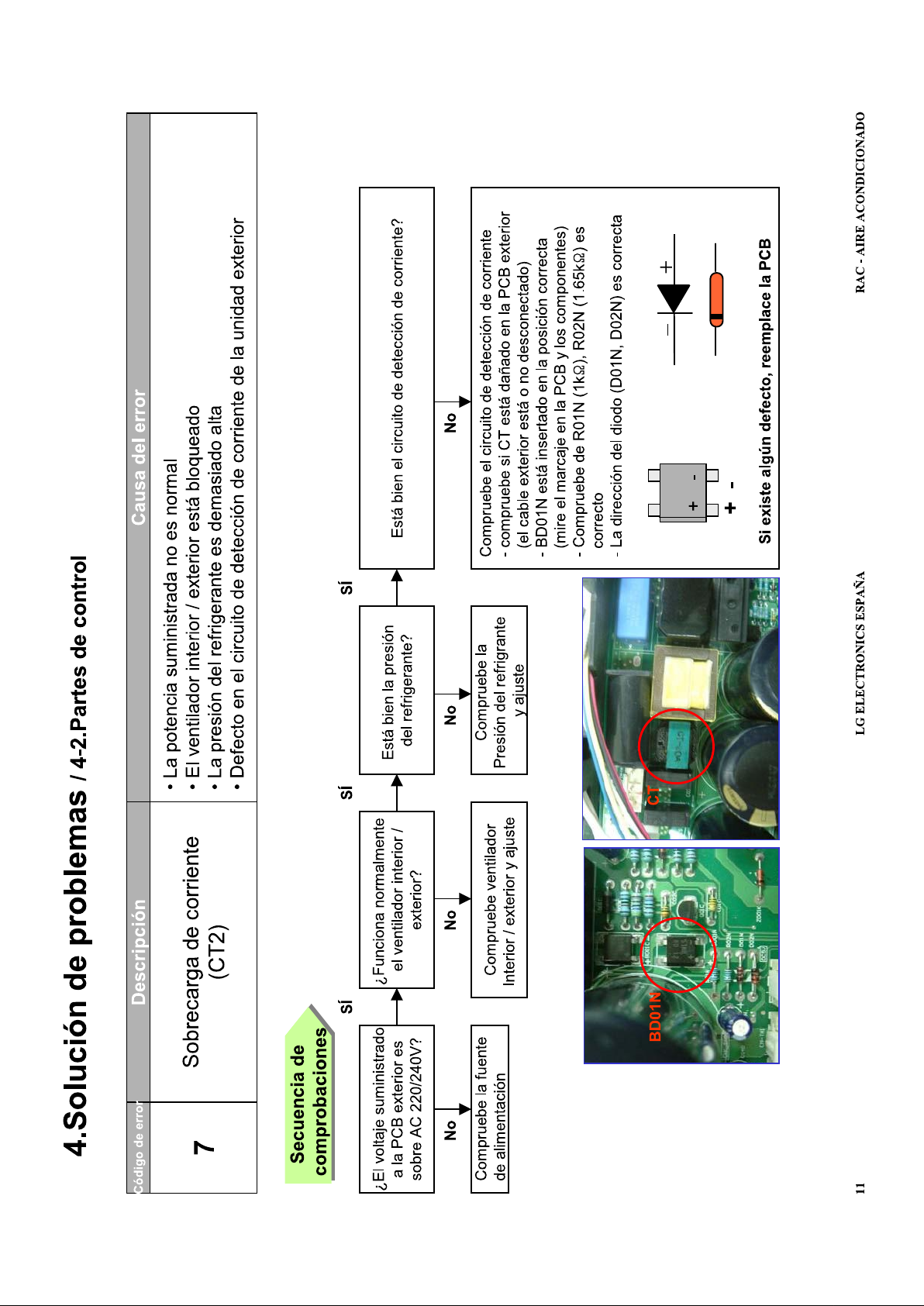
LG AC Fault Definition = Excessive compressor current
Flashing Light = 7
Display = Indoor Outdoor
Indoor Operation = SHUTDOWN
LG Split System Air Conditioner Error code = C8 or CH08
LG AC Fault Definition = Indoor fan not rotating
Flashing Light = 8
Display = Indoor
Indoor Operation = OFF
LG Split System Air Conditioner Error code = C9 or CH09
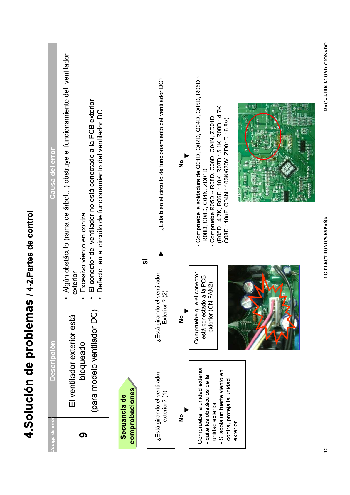
LG AC Fault Definition = Outdoor fan not rotating
Flashing Light = 9
Display = Indoor Outdoor
Indoor Operation = OFF
LG Split System Air Conditioner Error code = CA or CH10
LG AC Fault Definition = Discharge temp more than 130 °C – Faulty discharge thermistor
Flashing Light = 10
Display = Indoor Outdoor
Indoor Operation = ON
LG Split System Air Conditioner Error code = Flashing CH32
LG AC Fault Definition = Discharge temperature is high – Unit may be low on refrigerant or
airflow is blocked – dirty coil or air filter
Display = Indoor
Page 70

LG Split System Air Conditioner Error code = CC
LG AC Fault Definition = EEPROM error
Flashing Light = 2+1
Display = Outdoor
Indoor Operation = ON
LG Split System Air Conditioner Error code = CD
LG AC Fault Definition = Inverter module error
Flashing Light = 3+1
Display = Outdoor
Indoor Operation = ON
LG Split System Air Conditioner Error code = CL
LG AC Fault Definition = Child Lock Function selected – Not an error – Press Timer and Min
buttons at same time for 3 seconds to toggle On/Off
Indoor Status = On
LG Split System Air Conditioner Error code = HL
LG AC Fault Definition = High Limit (Float Switch) – Float switch Open circuit
Indoor Status = Off
LG Split System Air Conditioner Error code = Po
LG AC Fault Definition = System in Power Mode – (not a fault)
Display = Indoor
LG Split System Air Conditioner Error code = Lo
LG AC Fault Definition = System in test mode (not a fault)
Display = Indoor
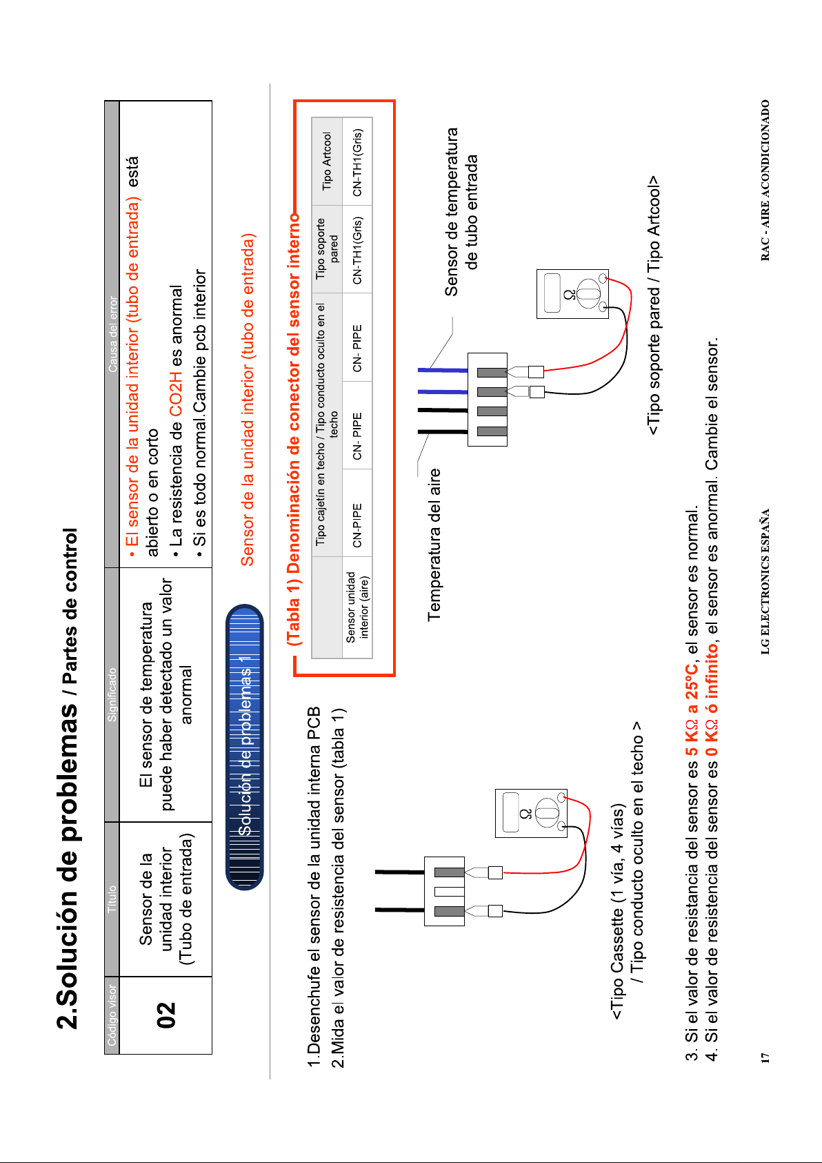
LG Split System Air Conditioner Error code = 01
LG AC Fault Definition = Air sensor (open/short) – Open / Short circuit
Indoor Status = Off
LG Split System Air Conditioner Error code = 02
LG AC Fault Definition = Inlet pipe sensor – Open / Short circuit
Indoor Status = Off
LG Split System Air Conditioner Error code = 03
LG AC Fault Definition = Communication (Indoor Wired R/Control) – Communication Issue
Indoor Status = Off
LG Split System Air Conditioner Error code = 04
LG AC Fault Definition = Drain pump / Float switch – Float switch Open circuit (High level water
alarm)
Indoor Status = Off
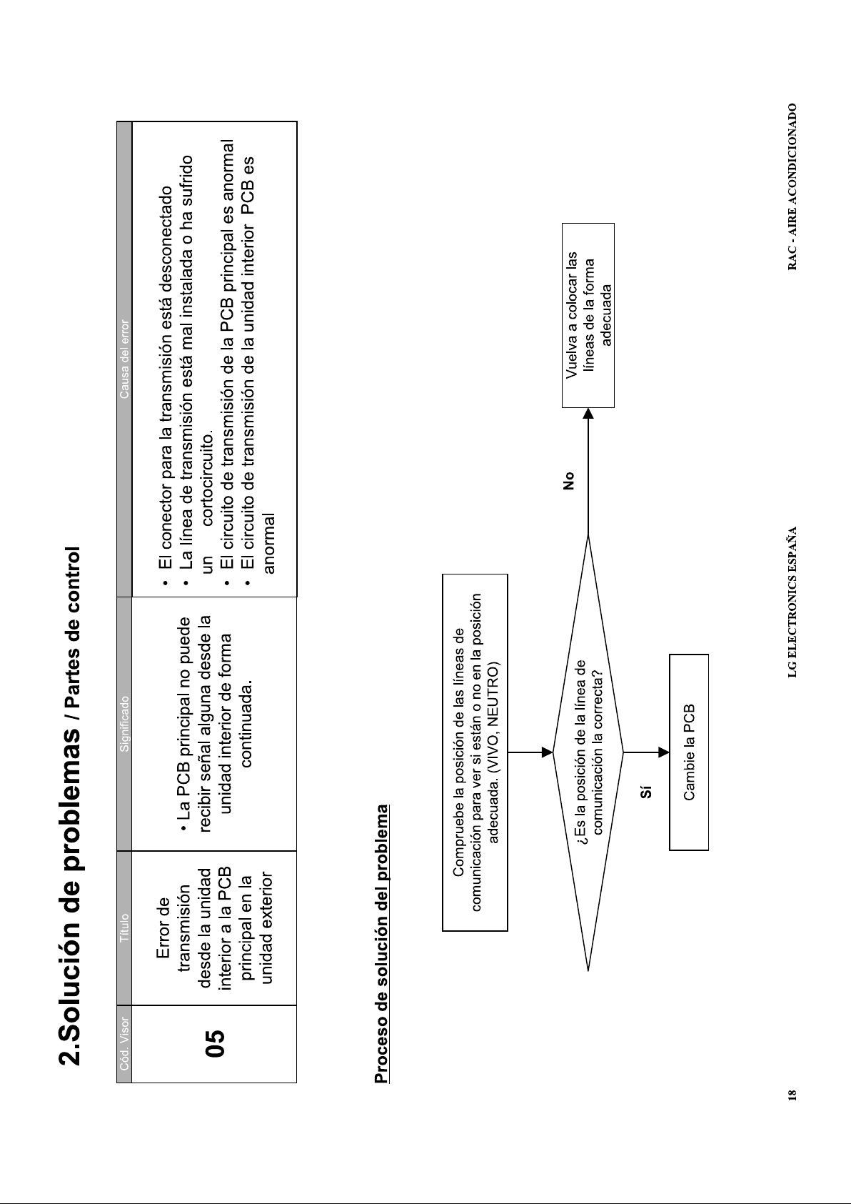
LG Split System Air Conditioner Error code = 05
LG AC Fault Definition = Communication(Indoor Outdoor) – Communication Issue
Indoor Status = Off
Page 71

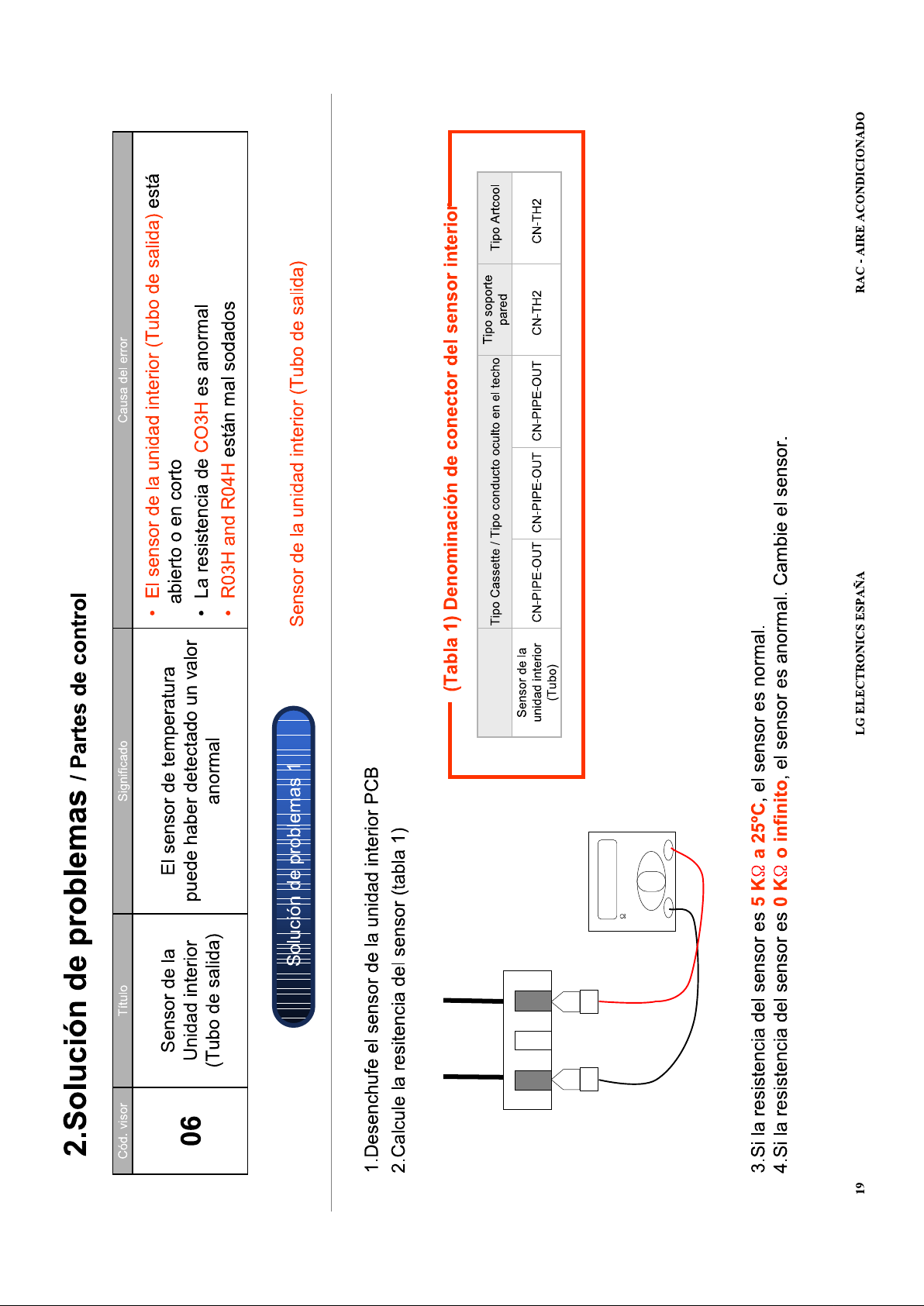
LG Split System Air Conditioner Error code = 06
LG AC Fault Definition = Outlet pipe sensor – Open / Short circuit
Indoor Status = Off
LG Split System Air Conditioner Error code = 07
LG AC Fault Definition = Different operation mode – Indoor units set in different operation modes
Indoor Status = Off
LG Split System Air Conditioner Error code = 21
LG AC Fault Definition = (Compressor Over-current) – Compressor malfunction, IPM Fault
LED01G = 2 times (Red)
LED02G = 1 time (Green)
Outdoor Status = Off
LG Split System Air Conditioner Error code = 22
LG AC Fault Definition = CT 2 Max. Current – Current is 14A
LED01G = 2 times (Red)
LED02G = 2 times (Green)
Outdoor Status = Off
LG Split System Air Conditioner Error code = 23
LG AC Fault Definition = DC Link Low Volt – DC Link volt
LED01G = 2 times (Red)
LED02G = 3 times (Green)
Outdoor Status = Off
LG Split System Air Conditioner Error code = 24
LG AC Fault Definition = Low / High Pressure – Low / High press switch OPEN
LED01G = 2 times (Red)
LED02G = 4 times (Green)
Outdoor Status = Off
LG Split System Air Conditioner Error code = 25
LG AC Fault Definition = AC Low / AC High Voltage – Abnormal AC volt input
LED01G = 2 times (Red)
LED02G = 5 times (Green)
Outdoor Status = Off
LG Split System Air Conditioner Error code = 26
LG AC Fault Definition = DC Compressor Position
LED01G = 2 times (Red)
LED02G = 6 times (Green)
Outdoor Status = Off
LG Split System Air Conditioner Error code = 27
LG AC Fault Definition = PSC Fault (Reactor)
LED01G = 2 times (Red)
LED02G = 7 times (Green)
Outdoor Status = Off
Page 72

LG Split System Air Conditioner Error code = 28
LG AC Fault Definition = DC Link High Volts – DC Link Voltage is 420V
LED01G = 2 times (Red)
LED02G = 8 times (Green)
Outdoor Status = Off
LG Split System Air Conditioner Error code = 32
LG AC Fault Definition = Discharge Pipe Temp High (INV)
LED01G = 3 times (Red)
LED02G = 2 times (Green)
Outdoor Status = Off
LG Split System Air Conditioner Error code = 33
LG AC Fault Definition = Discharge Pipe Temp High (Cons)
LED01G = 3 times (Red)
LED02G = 3 times (Green)
Outdoor Status = Off
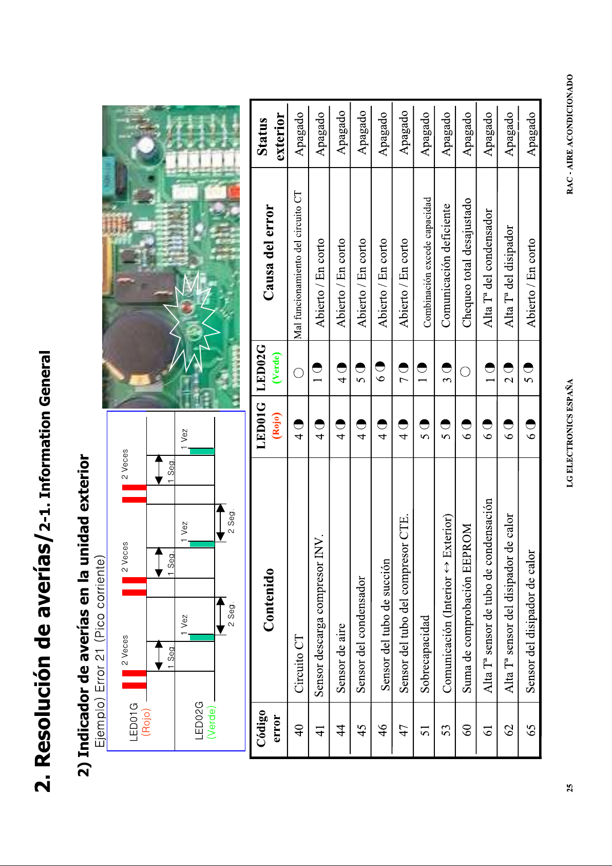
LG Split System Air Conditioner Error code = 40
LG AC Fault Definition = CT Circuit malfunction
LED01G = 4 times (Red)
Outdoor Status = Off
LG Split System Air Conditioner Error code = 41
LG AC Fault Definition = D-Pipe sensor INV (Open/Short) – Open / Short circuit
LED01G = 4 times (Red)
LED02G = 1 time (Green)
Outdoor Status = Off
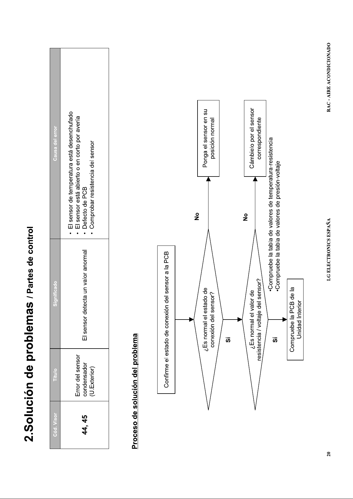
LG Split System Air Conditioner Error code = 44
LG AC Fault Definition = Air sensor Open / Short circuit
LED01G = 4 times (Red)
LED02G = 4 times (Green)
Outdoor Status = Off
LG Split System Air Conditioner Error code = 45
LG AC Fault Definition = Cond. Pipe Sensor Open / Short circuit
LED01G = 4 times (Red)
LED02G = 5 times (Green)
Outdoor Status = Off
LG Split System Air Conditioner Error code = 46
LG AC Fault Definition = Suction Pipe Sensor Open / Short circuit
LED01G = 4 times (Red)
LED02G = 6 times (Green)
Outdoor Status = Off
LG Split System Air Conditioner Error code = 47
LG AC Fault Definition = D-pipe Sensor Cons Open / Short circuit
LED01G = 4 times (Red)
LED02G = 7 times (Green)
Outdoor Status = Off
Page 73

LG Split System Air Conditioner Error code = 48
LG AC Fault Definition = D-Pipe & Air Sensor (Open) – Dual Sensor unplugged
LED01G = 4 times (Red)
LED02G = 8 times (Green)
Outdoor Status = Off
LG Split System Air Conditioner Error code = 51
LG AC Fault Definition = Over Capacity – Over Load Combination
LED01G = 5 times (Red)
LED02G = 1 times (Green)
Outdoor Status = Off
LG Split System Air Conditioner Error code = 52
LG AC Fault Definition = Communication Error (Main micom Sub micom) – Poor/Loss of
Communication
LED01G = 5 times (Red)
LED02G = 2 times (Green)
Outdoor Status = 0ff
LG Split System Air Conditioner Error code = 53
LG AC Fault Definition = Communication Error (Indoor Outdoor) – Poor/Loss of Communication
LED01G = 5 times (Red)
LED02G = 3 times (Green)
Outdoor Status = Off
LG Split System Air Conditioner Error code = 54
LG AC Fault Definition = Outdoor 3-Phase Power Supply Reverse Phase / Missing Phase –
Incorrect Wiring
LED01G = 5 times (Red)
LED02G = 4 times (Green)
Outdoor Status = Off
LG Split System Air Conditioner Error code = 60
LG AC Fault Definition = EEPROM Check Sum – Check Sum Mismatch
LED01G = 6 times (Red)
LED02G = (Green)
Outdoor Status = Off
LG Split System Air Conditioner Error code = 61
LG AC Fault Definition = Cond Pipe Sensor Temp High – Cond Temp High
LED01G = 6 times (Red)
LED02G = 1 time (Green)
Outdoor Status = Off
LG Split System Air Conditioner Error code = 62
LG AC Fault Definition = Heat-Sink Sensor Temp High
LED01G = 6 times (Red)
LED02G = 2 times (Green)
Outdoor Status = Off
Page 74

LG Split System Air Conditioner Error code = 63
LG AC Fault Definition = Cond Pipe Sensor Temp Low
LED01G = 6 times (Red)
LED02G = 2 times (Green)
Outdoor Status = Off
LG Split System Air Conditioner Error code = 65
LG AC Fault Definition = Heat-Sink Sensor Open / Short circuit
LED01G = 6 times (Red)
LED02G = 5 times (Green)
Outdoor Status = Off
LG Split System Air Conditioner Error code = 67
LG AC Fault Definition = Outdoor BLDC Fan Lock – Fan Motor/Circuit Problem
LED01G = 6 times (Red)
LED02G = 7 times (Green)
Outdoor Status = Off
LG Split System Air Conditioner Error code = 105
LG AC Fault Definition = Comms Error (Main board Fan board) – Poor/Loss of Communication
LED01G = 6 times (Red)
LED02G = 5 times (Green)
Outdoor Status = Off
Page 75

LG Air Conditioning - Universal Split Fault Codes Sheet
Tens
Units
“Universal” Split Systems
If there is a fault on any LG Universal unit, a two digit number will appear on the remote controllers led
display. If the unit does not have a remote controller the fault will be displayed using the LED's on the front of
the indoor unit.
Units Digit (Red) Tens Digit (Green)
The “Units” digit of the fault code is shown by the power led which has the following symbol by it
This is usually Red, but on a few models it is Green.
The “Tens” digit will be displayed by one other led, usually the “Sleep” or “Filter” lamp.
Error Indicator:
The function provides self-diagnosis and displays an error code if there is any trouble.
Error codes are displayed on the Indoor unit’s Wired Remote as CH**, and/or Fascia Display. In
addition, the code is indicated via LED’s on the outdoor unit control board.
If more than two troubles occur simultaneously, the lower number of error code is displayed first.
After an error occurs, if error is released, error LED is also released simultaneously.
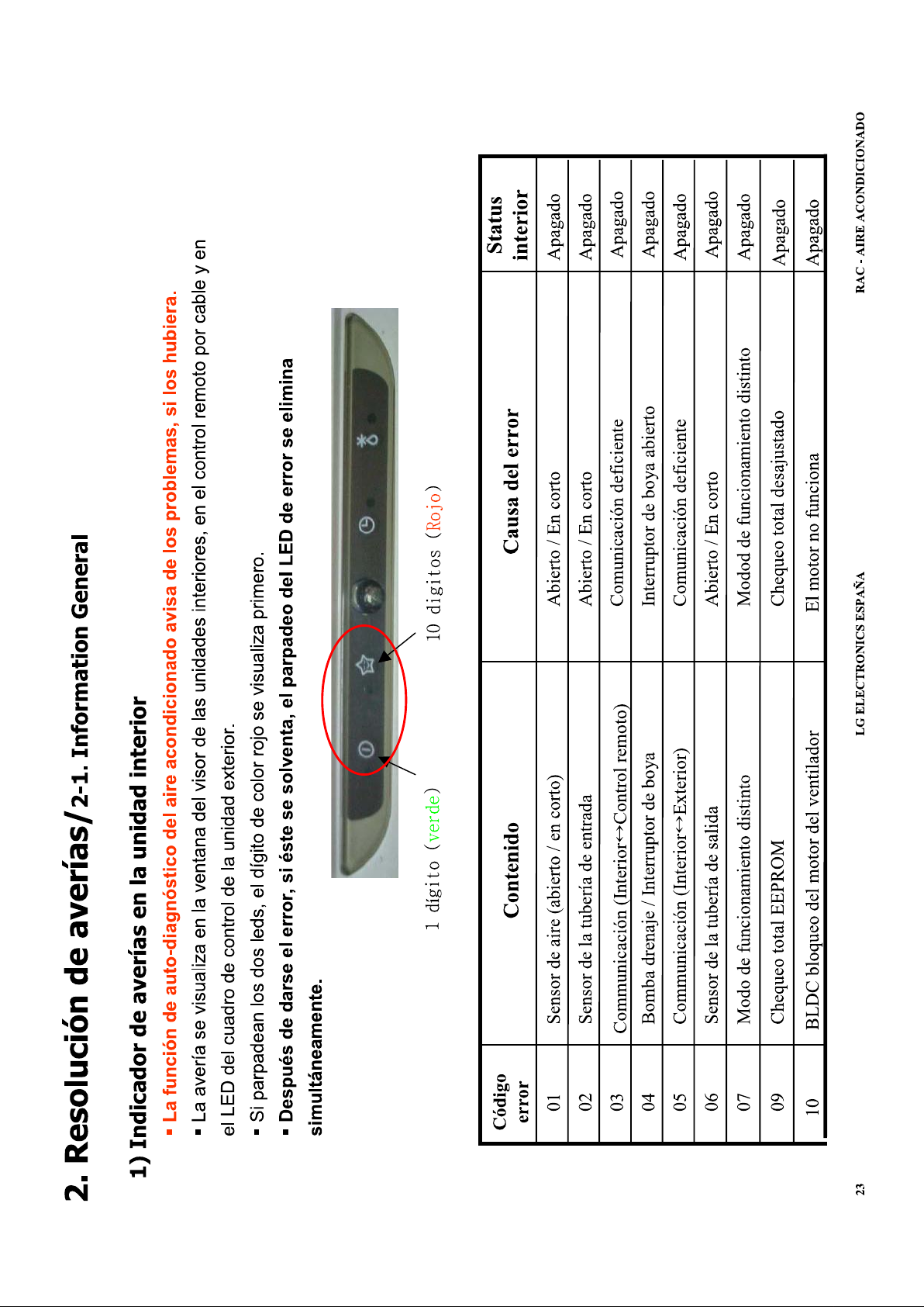
Indoor Unit Faults:
Error
code
Contents Case of error
Indoor
Status
01 Air sensor (open/short) Open / Short circuit Off
02 Inlet pipe sensor Open / Short circuit Off
Communication(Indoor ↔ Wired
03
R/Control)
04 Drain pump / Float switch
Communication Poorly Off
Float switch Open circuit (High level water
alarm)
05 Communication(Indoor ↔ Outdoor) Communication Poorly Off
06 Outlet pipe sensor Open / Short circuit Off
07 Different operation mode Indoor units set in different operation modes Off
09 Checksum Error Defective PCB or EEPROM Connections Off
10 BLDC Motor Fan Lock (Indoor) Fan Motor or PCB Defective Off
Off
HL Hard Lock (Controlled by External Source) Controlled by Dry Contact or Central Controller Off
CL Child Lock Function selected
Po Jet Cool Mode selected
Not an error, press Timer & Min buttons
simultaneously for 3 seconds to toggle On/Off
Not an error, press Jet Cool button to toggle
On/Off
On
On
Macedo - Oct 2010
- 1 -
Page 76

LG Air Conditioning - Universal Split Fault Codes Sheet
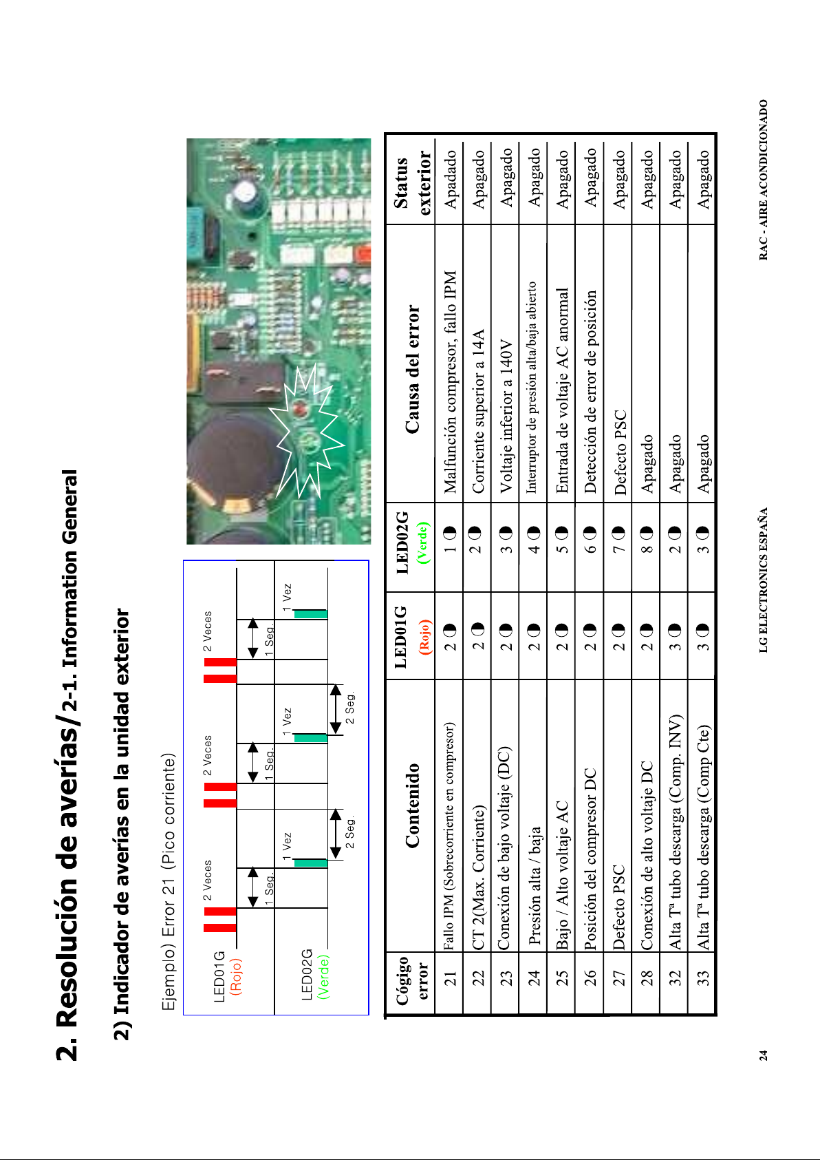
Outdoor Unit Faults can also be read from the outdoor unit PCB using the flashing LED’s as below:
Error
code
21 IPM Fault (Compressor Over current) 2 times 1 time
22 CT 2 (Max. Current) 2 times 2 times Current is 14A ↑ Off
23 DC Link Low Volt. 2 times 3 times DC Link volt. Is 140V ↓ Off
24 Low / High Pressure 2 times 4 times Low / High press switch OPEN Off
25 AC Low / AC High Volts. 2 times 5 times Abnormal AC volt. Input. Off
26 DC Compressor Position 2 times 6 times Off
27 PSC Fault (Reactor) 2 times 7 times Off
28 DC Link High Volts 2 times 8 times Off Off
29 COMP Over Current 2 times 9 times
32 Discharge Pipe Temp. High (INV) 3 times 2 times D-Pipe Temp (Inv.) >105°C Off
33 Discharge Pipe Temp. High (Cons.) 3 times 3 times D-Pipe Temp (Const) >105°C Off
39 Communication Error 3 times 9 times
40 CT Circuit 4 times CT Circuit malfunction Off
Contents
LED01G
(Red)
LED02G
(Green)
Case of Error
Compressor malfunction, IPM
Fault
Inverter Compressorinput
current is over 30A
Communication Error
Between PFC and INV PCB’s
Outdoor
Status
Off
Off
Off
41 D-Pipe sensor INV. (Open/Short) 4 times 1 time Open / Short circuit. Off
44 Air sensor (Open/Short) 4 times 4 times Open / Short circuit Off
45 Cond. Pipe Sensor (Open/Short) 4 times 5 times Open / Short circuit Off
46 Suction Pipe Sensor (Open/Short) 4 times 6 times Open / Short circuit Off
47 D-pipe Sensor Cons. (Open/Short) 4 times 7 times Open / Short circuit Off
48 D-Pipe & Air Sensor (Open) 4 times 8 times Dual Sensor unplugged Off
51 Over Capacity 5 times 1 times Over Load Combination Off
Communication Error (Main micom
52
↔ Sub micom)
Communication Error (Indoor ↔
53
Outdoor)
Outdoor 3-Phase Power Supply
54
Reverse Phase / Missing Phase
60 EEPROM Check Sum 6 times Check Sum Mis-Match Off
61 Cond. Pipe Sensor Temp. High 6 times 1 time Cond. Temp. High Off
62 Heat Sink Sensor Temp. High 6 times 2 times Heat Sink Temp. High Off
63 Cond. Pipe Sensor Temp. Low 6 times 3 times Cond. Temp. Low Off
5 times 2 times Poor/Loss of Communication Off
5 times 3 times Poor/Loss of Communication Off
5 times 4 times Incorrect Wiring Off
65 Heat Sink Sensor (Open/Short) 6 times 5 times Open / Short circuit Off
67 Outdoor BLDC Fan Lock 6 times 7 times Fan Motor/Circuit Problem Off
73 PFC Fault Error (S/W) 7 times 3 times
105
Comms. Error (Main board ↔Fan
board)
[The codes are explained in detail on the following pages]
6 times 5 times Poor/Loss of Communication Off
Inverter PCB input current is over
48A (Peak) for 2ms
Macedo - Oct 2010
- 2 -
Page 77

LG Air Conditioning - Universal Split Fault Codes Sheet
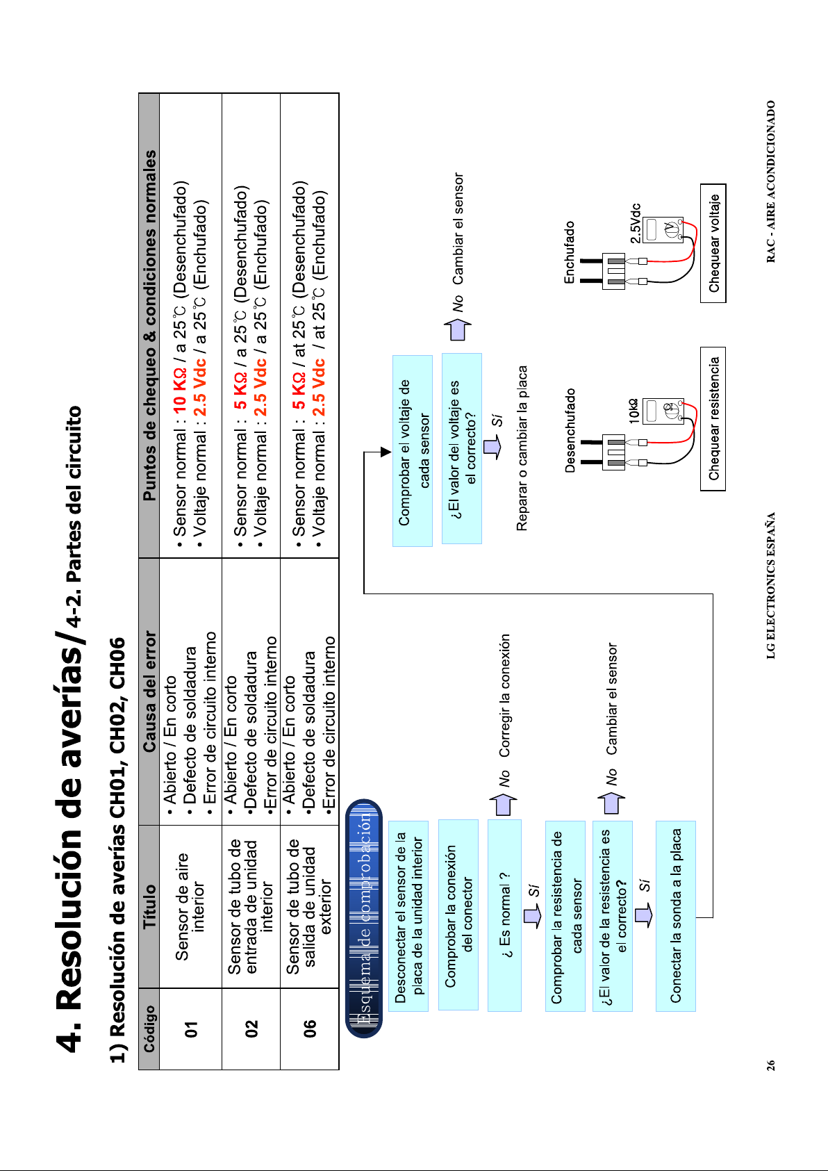
Fault code 01
Is a fault with the Indoor unit return air Thermistor
Unplug the Thermistor from the PCB and Check its resistance check against this graph:
Resistance of Air thermistor
20
18
16
14
12
10
8
Resistancek Ohms
6
10 15 20 25 30 35 40
Temperature
Alternatively the sensor can be tested while still connected to the PCB measure the DC voltage across the
resistor and check it against the graph below.
Voltage across Air thermistor
3.5
3.0
2.5
Volts DC
2.0
1.5
10 15 20 25 30 35 40
Temperature
Macedo - Oct 2010
- 3 -
Page 78

LG Air Conditioning - Universal Split Fault Codes Sheet
Fault code 02
Is a problem with the Indoor unit coil inlet Thermistor
Unplug the Thermistor from the indoor PCB and Checkits resistance against this graph:
Coil thermistor resistance k Ohms
20
15
10
5
Resistance k Ohms
0
0 10 20 30 40 50 60 70
Temperature
Alternatively the sensor can be tested while still connected to the PCB measure the DC voltage across the
resistor and check it against the graph below.
Voltage across coil thermistor
4.0
3.0
2.0
Volts DC
1.0
0.0
0 10 20 30 40 50 60 70
Temp
Macedo - Oct 2010
- 4 -
Page 79

LG Air Conditioning - Universal Split Fault Codes Sheet
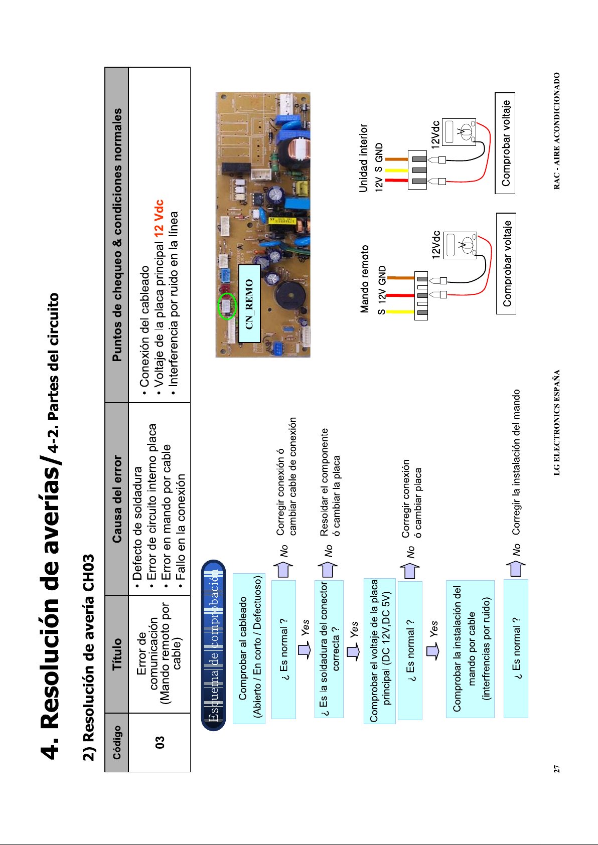
Fault Code 03
Indicates a wiring error between the remote controller and the fan coil, this is most common in group control
applications where more than 1 fan coil is connected to a single remote controller.
Firstly check the wiring has been done correctly see below.
1 2 3
Next check the switch in the back of the remote controller, it has to be set to Group or GR1 for group control,
the Factory setting is Single or SG, after setting the switch reset the power for 2 minutes. If the fault does not
clear, check the Voltage of the remote controller cable.
2 3
2 3
The Red cable is 12 Vdc
The Brown or Black cable is Ground or 0 Vdc
The Yellow is signal (Comms.)
Test
Voltage across the Brown/ Black cable and the Red, this
should be 12 Vdc
Voltage from Yellow to Brown/Black this should be
fluctuating between 8 – 12 Vdc.
Macedo - Oct 2010
- 5 -
Page 80

LG Air Conditioning - Universal Split Fault Codes Sheet
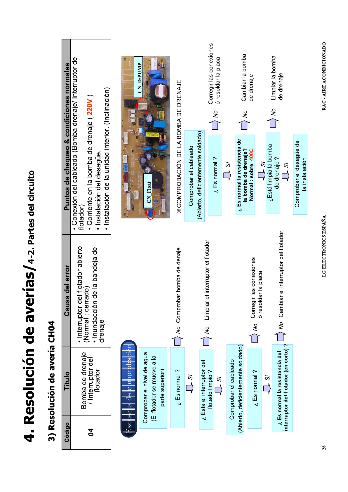
Fault Code 04
Fault code CH04 indicates that the float switch of the fan coil has risen.
On fan coils without a drain pump it indicates that the jumper (blue plug with 30mm of blue wire) in terminal
CN FLOAT is missing.
If the fan coil is running and the float rises it will take 3 ½ minutes for the fault to show on the controller, this is
to give the unit time to pump excess water away. Once the float falls, (or the jumper is put back into the board)
it will not be possible to clear the fault for 40 seconds. It is considered good practice to reset the power to
clear this fault code.
Fault Code 05
These error codes indicate a communication fault between the indoor and outdoor units; it appears
approximately 5 minutes after powering up the system.
The communication between the units is a fluctuating DC voltage commonly called a serial signal, it can be
easily lost if the wiring is not done correctly. If there is a communication error fault CH05 will appear on the
Wired Remote within 5 mins of powering up the system.
Testing
First check for any isolator or switches on the interconnecting cable and ensure both the Comms and Neutral
are un-switched. Then confirm connections are correct and secure at both the Indoor and Outdoor units.
Check if any other devices are connected on the interconnecting cable, remove such equipment, and connect
them elsewhere.
Open the outdoor unit to reveal the Main PCB and identify the Green and Red LED’s on that board. The
Green LED should be lit steadily if power is present, the Red LED should be doing one of the following:-
1. If the outdoor unit receives communicationsfrom the indoor unit, the Red LED should be flickering.
2. If the Red LED glows steadily without flickering, then no communication is being received from the
indoor unit. Check the interconnecting cables for any short or open circuits, not forgetting the
connecting cables between the terminal rail and PCB on both Indoor & Outdoor units. Repair wiring,
or replace the Indoor PCB as necessary.
3. If the Red LED does not light at all, then the fault is with the outdoor PCB, or connections to it. Confirm
that the Outdoor PCB is receiving power (Green LED lit). Repair wiring, or replace the Outdoor PCB
as necessary.
4. If Condition 3 above applies please check the following and repair/replace as required. Failure to do so
may result in the new PCB becoming damaged.
a. Check PCB Control Fuse, if blown, identify cause and rectify.
b. Check Fan Motor(s).
i. AC Motors for Short Circuits or Down to Earth.
ii. BLDC Motors (See Product Technical Update - Sheet 83).
c. Reversing Valve Coil, for Short Circuit or Down to Earth.
d. Reactor, for Open Circuit.
e. Electronic Expansion Valve Down to Earth (See Product Technical Update - Sheet 96).
f. Compressor, for Short Circuit or Down to Earth.
Additional Tests:
Set your meter to DC Volts, Test between terminals 2 and 3 of the outdoor unit and wiring terminals, you
should see 0-75 Vdc, it will be fluctuating rapidly.
If this signal voltage is not present disconnect the wire from terminal 3 of the inter unit cabling, and test
terminal 3 Voltage again. If Voltage is still not present, the outdoor PCB must be faulty.
If this signal voltage is detected leaving the outdoor unit, reconnect wire 3 and check what is being received at
the indoor unit. Disconnect wire 3 from the indoor terminal block and check the DC Voltage between this wire
and terminal 2. It should be the same as what you saw at the outdoor unit, if not your wiring is at fault.
With the wire still disconnected, check between terminals 2 & 3. You should see a relatively steady voltage in
the range of 0.5 – 15Vdc (Negative). Any significant difference would indicate a faulty Indoor PCB.
Important: Comms Errors are also created on Universal “Synchro Systems” when they are not
configured/commissioned correctly. Please follow the correct Synchro Commissioning Procedures.
Macedo - Oct 2010
- 6 -
Page 81

LG Air Conditioning - Universal Split Fault Codes Sheet
Fault code 06
Is a problem with the Indoor unit coil outlet Thermistor
Unplug the Thermistor from the indoor PCB and Checkits resistance against this graph:
Coil thermistor resistance k Ohms
20
15
10
5
Resistance k Ohms
0
0 10 20 30 40 50 60 70
Temperature
Alternatively the sensor can be tested while still connected to the PCB measure the DC voltage across the
resistor and check it against the graph below.
Voltage across coil thermistor
4.0
3.0
2.0
Volts DC
1.0
0.0
0 10 20 30 40 50 60 70
Temp
Macedo - Oct 2010
- 7 -
Page 82

LG Air Conditioning - Universal Split Fault Codes Sheet
Fault Code 07
On Multi split systems, the first unit switched on is the cool heat master, the master tells the condensing unit
what to do. If the condenser is in heating and any slave is set to cooling a CH07 fault code will appear.
Likewise if the condenser is in cooling and any slave is set to heating a CH07 fault code will appear. If the
master is switched off the next longest running unit becomes the master.
To clear the fault turn off the unit at the remote controller, turn it back on again and change the mode
Fault Code 09
Check for loose connections or dry joints where EEPROM connects on Main PCB, repair if possible, if not
replace PCB.
Fault Code 10
Indoor Fan Motor problem, See Fault Code 67 for Troubleshooting help.
Fault Code 21
This fault is caused by an over current in the inverters DC power circuit. If the DC part of the circuit exceeds
14 Amps fault code 21 will be displayed.
This is caused by either the inverter PCB being faulty or compressor being short circuit or down to earth.
Disconnect the electrical connections to the compressor and check
the resistance of the compressor windings, measure from U to V, V
to W and W to U the values should be between 0.25 and 5 Ohms
each.
The next test is to measure the resistance of the compressor
windings to earth.
Using a Megger (High Voltage Meter) measure the resistance from
any of the 3 compressor terminals to an Earth point (pipe work).
The value should exceed 2 M Ohms.
If the compressors fail these tests it will need replacing.
If the compressor is OK you will need to check the inverter output voltages. Please see section on Inverter
testing at end.
Fault Code 22
This fault is caused by a Compressor over-current see code 21
Please see section on Inverter testing at the end.
Fault Code 23
This fault indicates a fault in the DC part of the inverter circuit; it means that the Dc Voltage to the inverter is
below 140 V Dc, it should be 370 V for single phase machines and 600 V dc for three phase machines. The
Macedo - Oct 2010
- 8 -
Page 83

LG Air Conditioning - Universal Split Fault Codes Sheet
fault is usually caused by the inverter charging resistor being faulty; this component is mounted on the outdoor
unit PCB and cannot be replaced.
Start the unit running and measure the DC Voltage supply to the inverter. This is easiest to measure at the
inverter capacitors; it should be 370 V for single phase machinesand 600 V dc for three phase machines
See section on Inverter testing at the end.
Fault Code 24
If the unit has a low or high pressure fault CH24 will display.
If the LP switch goes open circuit the compressor will be stopped, on inverter units this can take up to 30
seconds. The LP Switch goes open circuit when the suction pressure falls below 0.5 bar the Hp Switch opens
at 41 bar.
The fault code will only occur if the pressure switch is tripped 5 times within 1 hour, this can only be reset by
switching off the power to the condensing unit for 2 minutes.
If your unit does not have any pressure switches it may still have a plug on the outdoor unit PCB labelled CN
Press, it should have a link plugged in, if the link is missing it must be replaced.
Fault Code 25
This fault indicates a problem with the incoming power supply to the system.
Measure the Voltage of the incoming supply, if it is less than 140V AC or greater than 300V AC this fault will
occur.
If the Power supply is correct and the fault persists replace the outdoor unit PCB.
Fault Code 26
This fault indicates a problem with the positioning system of the inverter compressor, which indicates a seized
compressor.
Firstly check the compressor is correctly connected. Next reset the power supply to the system ensuring the
power is left off for 5 minutes. Start the unit up, after a couple of minutes the compressor will try and start, you
can hear a high pitched whine when it does. If the compressor does not start turning within a couple of
seconds the whining will stop. The compressor will try to start 3 times then the fault will recur.
Fault Code 27
This fault indicates a problem with the inverter module, see section on testing inverters. Also check reactor is
connected to the PCB and check its resistance it should be well under 1 Ohm.
Fault Code 28
This fault indicates a problem in the DC part of the inverter circuit; it means that the DC Voltage to the inverter
is too high.
Start the unit running and measure the DC Voltage supply to the inverter. This is easiest to measure at the
inverter capacitors; it should be 370 V for single phase machinesand 600 V dc for three phase machines. See
section on Inverter testing at end.
Fault Code 29
Check and correct for any:
1. Overload operation (Pipe restrictions/ Restricted Airflow / EEV defect / Refrig. Overcharged)
2. Compressor damage (Insulation damage / Motor damage)
3. Input Voltage Low
4. ODU Inverter PCB assembly damage
Macedo - Oct 2010
- 9 -
Page 84

LG Air Conditioning - Universal Split Fault Codes Sheet
Fault Code 32
Indicates that the Inverter compressor discharge temperature is high (above 105ºC) this usually indicates the
system has either a shortage of refrigerant or a blockage in the system.
Reset the power to the unit for 2 minutes and restart it. If the compressor starts measure the compressor
discharge temperature, typically it should not be more than 50ºC above the ambient temperature around the
condensing unit. It may take quite a long period for the compressor to overheat so don’t just start the unit and
run. Make sure you check the unit is operating correctly and providing adequate cooling.
Fault Code 33
Indicates that the fixed speed compressor discharge temperature is high (above 105ºC) this usually indicates
the system has either a shortage of refrigerant or a blockage in the system.
Reset the power to the unit for 2 minutes and restart it, If the compressor starts measure the compressor
discharge temperature, typically it should not be than 50ºC above the ambient temperature around the
condensing unit. It may take quite a long period for the compressor to overheat so don’t just start the unit and
run. Make sure you check the unit is operating correctly and providing adequate cooling.
Fault Code 39
Check and repair or replace as necessary:
1. PCB defect / Wiring defect
2. Different Micom Software Version
3. ODU Inverter PCB assembly damage
Fault Code 40
This fault indicates a problem with the current drawn by the AC part of the inverter circuit.
Refer to the inverter testing procedure at the end.
Macedo - Oct 2010
- 10 -
Page 85

LG Air Conditioning - Universal Split Fault Codes Sheet
Fault Code 41
This fault indicates an Inverter Compressor discharge Thermistor fault
Unplug the Thermistor and Check its resistance check against this graph:
Resistance of discharge pipe thermistor
250
200
150
100
50
resistance kOhms
0
20 30 40 50 60 70 80 90 100 110
temp
Alternatively the sensor can be tested while still connected to the PCB measure the DC voltage across the
resistor and check it against the graph below.
Voltage acrossdischarge thermistor
5.0
4.5
4.0
3.5
3.0
2.5
Voltage DC
2.0
1.5
1.0
20 30 40 50 60 70 80 90 100 110
Temp
Macedo - Oct 2010
- 11 -
Page 86

LG Air Conditioning - Universal Split Fault Codes Sheet
Fault Code 44
Indicates a fault with the Outdoor unit air Thermistor
Unplug the Thermistor from the PCB and Check its resistance check against this graph:
Resistance of Air thermistor
20
18
16
14
12
10
8
Resistancek Ohms
6
10 15 20 25 30 35 40
Temperature
Alternatively the sensor can be tested while still connected to the PCB measure the DC voltage across the
resistor and check it against the graph below.
Voltage across Air thermistor
3.5
3.0
2.5
Volts DC
2.0
1.5
10 15 20 25 30 35 40
Temperature
Macedo - Oct 2010
- 12 -
Page 87

LG Air Conditioning - Universal Split Fault Codes Sheet
Fault Code 45
Indicates a problem with the condenser coil outlet Thermistor
Unplug the Thermistor from the indoor PCB and Checkits resistance against this graph:
Coil thermistor resistance k Ohms
20
15
10
5
Resistance k Ohms
0
0 10 20 30 40 50 60 70
Temperature
Alternatively the sensor can be tested while still connected to the PCB measure the DC voltage across the
resistor and check it against the graph below.
Voltage across coil thermistor
4.0
3.0
2.0
Volts DC
1.0
0.0
0 10 20 30 40 50 60 70
Temp
Macedo - Oct 2010
- 13 -
Page 88

LG Air Conditioning - Universal Split Fault Codes Sheet
Fault Code 46
Indicates a problem with the compressor suction Thermistor
Unplug the Thermistor from the indoor PCB and Checkits resistance against this graph:
Coil thermistor resistance k Ohms
20
15
10
5
Resistance k Ohms
0
0 10 20 30 40 50 60 70
Temperature
Alternatively the sensor can be tested while still connected to the PCB measure the DC voltage across the
resistor and check it against the graph below.
Voltage across coil thermistor
4.0
3.0
2.0
Volts DC
1.0
0.0
0 10 20 30 40 50 60 70
Temp
Macedo - Oct 2010
- 14 -
Page 89

LG Air Conditioning - Universal Split Fault Codes Sheet
Fault Code 47
Indicates an Inverter Compressor discharge Thermistor fault
Unplug the Thermistor from the PCB and Check its resistance check against this graph:
Resistance of discharge pipe thermistor
250
200
150
100
50
resistance kOhms
0
20 30 40 50 60 70 80 90 100 110
temp
Alternatively the sensor can be tested while still connected to the PCB measure the DC voltage across the
resistor and check it against the graph below.
Voltage acrossdischarge thermistor
5.0
4.5
4.0
3.5
3.0
2.5
Voltage DC
2.0
1.5
1.0
20 30 40 50 60 70 80 90 100 110
Temp
Macedo - Oct 2010
- 15 -
Page 90

LG Air Conditioning - Universal Split Fault Codes Sheet
Fault Code 48
This fault indicates that the compressor discharge sensor and the condenser air temperature sensors are both
unplugged. Both these sensors are connected to a single connector on the outdoor unit PCB, plug it in and
the fault will go away.
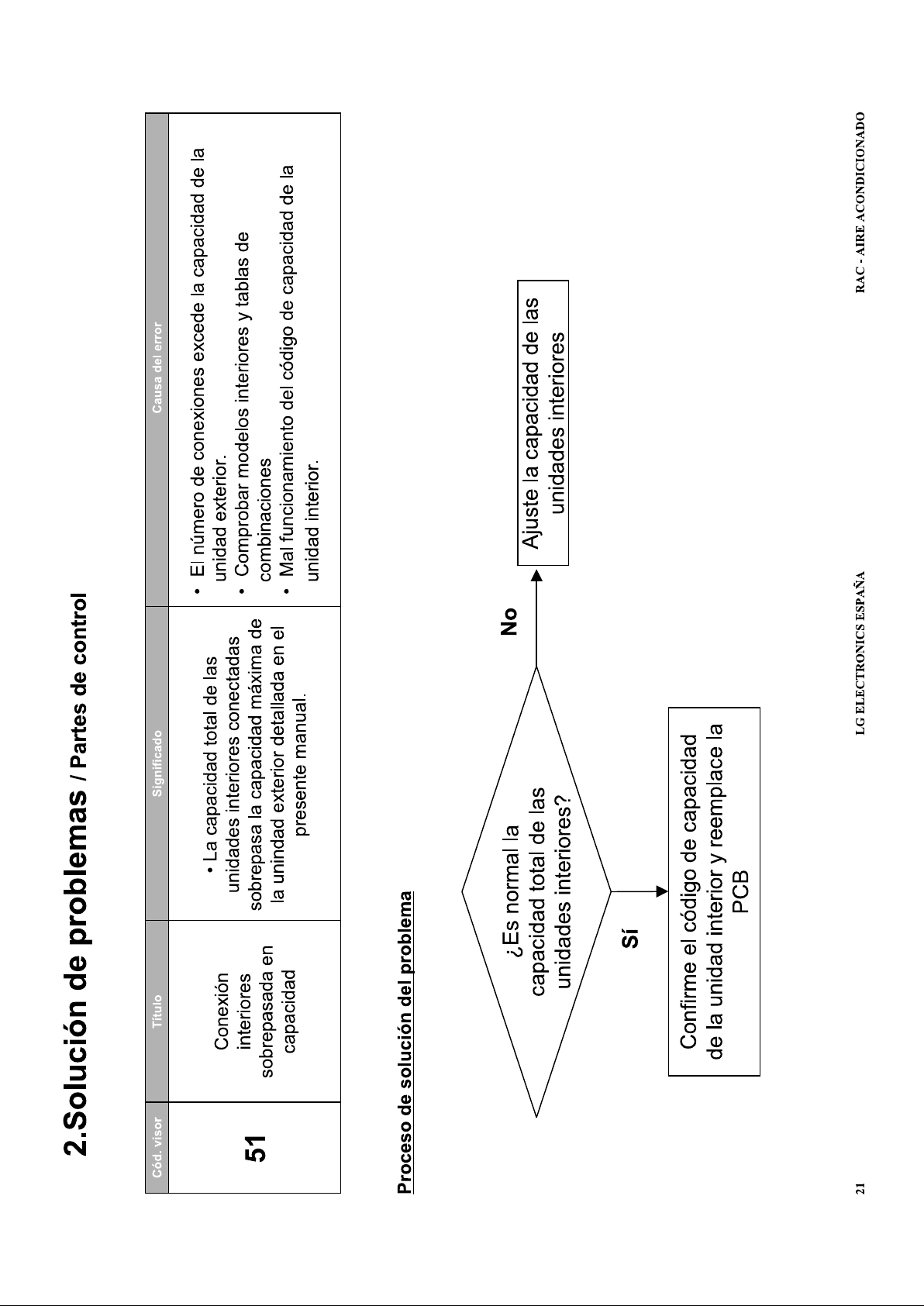
Fault Code 51
This indicates that the capacity of the indoor unit / units is too great for the condensing unit. Make a note of
the model number of the fan coil/coils and the condensing unit and check with the equipment supplier that the
units you have installed can be connected together.
Fault Code 52
This fault code indicates a communication error between the Main and Sub micom (CPU’s) on the outdoor
unit main PCB. Check for evidence of damage, if none found reset power, if fault reappears replace pcb.
Fault Code 53, (see fault code 05)
Fault Code 54
This fault normally indicates a lost phase or the phases are reversed on the power supply to 3 phase units.
Check all 3 phasesare available at the power terminals to the unit. You should have 415v AC across red to
blue, blue to yellow and red to yellow,
If this is all ok turn off the power and swap the red and yellow cores of the power supply cable over, reset the
power and the unit will operate.
Fault Code 60
Check the correct PCB assembly has been installed, check for dry joints, replace outdoor unit PCB if nothing
is found.
Fault Code 61
Indicates the outdoor unit condenser coil temperature is high above 65ºC, this will usually be experienced in
cooling mode and will indicate insufficient air being drawn over the coil.
Check there are no blockages to the coil (carrier bags dirt etc); check the air flow is not short circuiting from
the front to the back of the unit and check for Nitrogen in the system.
Fault Code 62
Indicates the outdoor unit Inverter heat-sink thermistor has detected that the heat sink is overheating 85ºC.
This is usually caused by debris blocking the heat-sink fins or an error with the thermistor, see code 65.
Macedo - Oct 2010
- 16 -
Page 91

LG Air Conditioning - Universal Split Fault Codes Sheet
Fault Code 65
Is a problem with the Inverter PCB heat sink thermistor for the heat sink on the outdoor unit PCB, unplug the
Thermistor from the PCB and Check its resistance against this graph:
resistance of Heat sink thermistor
20
18
16
14
12
10
8
Resistance k Ohms
6
10 15 20 25 30 35 40
Temperature
Alternatively the sensor can be tested while still connected to the PCB measure the DC voltage across the
resistor and check it against the graph below.
Voltage across Heat Sink thermistor
3.5
3.0
2.5
Volts DC
2.0
1.5
20 25 30 35 40
Temperature
Macedo - Oct 2010
- 17 -
Page 92

LG Air Conditioning - Universal Split Fault Codes Sheet
Fault Code 67
This is a problem with the Outdoor Fan Motor, where rotation is not detected, and could be result of either
Mechanical or Electrical failure.
Check that motor is free to rotate and not seized.
Check the motor is electrically sound, windings not Open or Short circuit.
Check power output from PCB to fan motor.
Check rotation feedback circuit.
More modern units use inverter fan motors, which are powered by a DC Voltage.
In reality these fan motors are AC fan motors with a small inverter-type circuit build inside. This inverter circuit
is integrated with the fan motor and impossible to replace, you have to replace the entire fan motor.
Similar to inverter-controlled compressors, the speed of these fan motors can be changed to whatever is
needed (within certain limits). In practice the change in fan speed is not ‘continuous’ but certain fixed speeds
have been programmed inside the AC unit.
This type of fan control can be recognized by the 5 wirescoming from the fan on a connector with 7 possible
connections
These fan motors have 5 connections, power supply is 360VDC, and the speed is determined by a voltage
ranging from 0 (0 rpm) to 5VDC (max speed) and a power supply for the internal electronics of 15VDC.
These motors are easy to identify from a wiring diagram, they always show them not connected to anything as
the electronics are too difficult to draw on the diagram.
Detail of Hall Sensors
A Hall effect sensor works like a magnetic reed switch, one end is wired to a 15 Vdc supply and the other is
the feed back to the PCB. As a magnet mounted on the rotor of the motor passes the hall sensor the reed
switch closes momentarily and allows the DC signal to flow through it back to the PCB. The hall sensors have
a resistance so the voltage fed back to the PCB will only be approximately 12V DC.
The pcb will know what speed the fan motor should be turning as it is also controlling the output of the
inverter, if there is a discrepancy between the inverter output RPM and the feedback from the hall sensors a
fault will occur. Usually the fan will rev very fast for a few seconds then stop this indicates hall sensor
problems.
Replace either Motor or Fan PCB as necessary.
Fault Code 73
Check and repair or replace as necessary:
1. Overload operation (Pipe restrictions/ Restricted Airflow / EEV defect / Refrig. Overcharged)
2. Compressor damage (Insulation damage / Motor damage)
3. Input Voltage abnormal
4. Power supply wiring abnormal
5. Inverter PCB assembly damage
Fault Code 105
This is due to a Communication error between the Main outdoor PCB and Fan PCB.
Check for Open/Short of communicationline between the Main and Fan PCB’s.
Check communication cable plug connections.
Is the communication LED on?
Macedo - Oct 2010
- 18 -
Page 93

LG Air Conditioning - Universal Split Fault Codes Sheet
Testing Inverters
It is best to test inverters with no compressors connected especially if you expect the compressor is at fault.
But if you remove the wires from the compressor and try to run the systems a fault will be displayed. The fault
is caused by the inverter PCB being able to detect whether a compressor is connected or not. Most modern
inverters are able to detect whether the compressor has been disconnected in only a few seconds making
testing very difficult.
Testing can be done in two ways:
Firstly the hard way……
You will need a digital multi meter with a min max function,
Turn off the power
Disconnect the compressor either from the PCB or at the compressor terminals.
Connect your meter to two of the phases (Red to blue) set your meter to record max and min voltage
Power up and Start the unit
Let the inverter start and watch the Voltage rise
Record the maximum Voltage
The inverter will stop after a few seconds and the voltage will fall to 0
Swap the leads to measure the next two phases (Red to Yellow).
Measure as before
Repeat for the last two phases Blue to Yellow.
The readings of maximum voltage should be the same for all 3 measurements if not the inverter is faulty, the
PCB will need replacing.
If the readings are equal the Inverter is healthy and the compressor will need replacing.
And the easy way:
You will need an LG Inverter tester,
Turn off the power
Disconnect the compressor lead from the compressor terminals.
Connect your inverter tester to all 3 leads (polarity is not important)
Power up and Start the unit
Let the inverter start and watch the led’s
All 6 must light up and should be of equal brightness
The inverter will stop after a few seconds and the led’s will go out
If you miss the led’s (they will only light for a couple of seconds) the unit will try to start again 3 times with a 3
minute delay between each test
If all 6 led’s DON’T light up the inverter is faulty, the PCB will need replacing.
If the led’s all light up the Inverter is healthy and the compressor will need replacing.
Macedo - Oct 2010
- 19 -
 Loading...