

LG AHUW146A2, AHUW166A3, AHUW128A3, AHUW146A3, AHUW168A3 User Manual
...
Air-to-Water Heat Pump
Original instruction
Please read this installation manual completely before installing the product.
Installation work must be performed in accordance with the national wiring
standards by authorized personnel only.
Please retain this installation manual for future reference after reading it
thoroughly.
INSTALLATION MANUAL
AIR-TO-WATER
HEAT PUMP
MFL69676201
Rev.02_072419
www.lg.com
Copyright © 2016 - 2019 LG Electronics Inc. All Rights Reserved.
ENGLISH
ITALIANO
ESPAÑOL
FRANÇAIS DEUTSCH
ΕΛΛΗΝΙΚΆ
ČEŠTINA
NEDERLANDS
POLSKI
LIMBA ROMÂNĂ
Table of contents
TABLE OF CONTENTS
3 SAFETY INSTRUCTIONS
4 Symbols
4 General
5 Safety warnings and instructions
10 Obligations of the manufacturer
10 Obligations of the installer during installation
10 Obligations of the user
11 INSTALLATION PART
12 GENERAL INFORMATION
12 Model Information
14 Parts and Dimensions
17 INSTALLATION OF OUTDOOR UNIT
17 Conditions where Outdoor Unit is Installed
18 Set up and connection of the external sensor
18 Drill a Hole in the Wall
19 Installation at Seaside
19 Seasonal wind and cautions in winter
20 INSTALLATION OF INDOOR UNIT
20 General
21 Location of the device
23 Connection with the outdoor unit
27 Hydraulic connection
36 Electrical connection
49 PIPING AND WIRING FOR OUTDOOR UNIT
49 Refrigerant Piping
53 Electrical Wiring
58 Finalizing
59 Leakage test and Evacuation
61 SYSTEM SET-UP
61 DIP Switch Setting
62
CHECK POINTS, MAINTENANCE AND TROUBLESHOOTING
62 Check List before Starting Operation
63 Care and Maintenance
65 Test Run
65 Limiting concentration
66 Airborne Noise Emission
66 SEARCH THE MANUAL USING YOUR MOBILE
2 Air-to-Water Heat Pump

Safety Instructions
ENGLISH
Safety Instructions
The manual describes the process of installation and maintenance of the
device. The installation and maintenance can only be performed by
qualified personnel. Read the manual carefully before the installation, this
way you will be informed about the intended use, functionality and
process of handling the device.
• The manual has to be handed over to the end user after installation.
• If this product is being handed over to a third person, ensure that you
provide them with this manual too.
Definitions
• An informed person is a person who reads this manual.
• A qualified person has a certificate of expert qualifications.
• The authorized technician is trained and authorized by the manufacturer
to perform maintenance and servicing of the device.
• The user uses the device according to its use.
• The installer is a person professionally trained for performing hardware
and/or electric installation work and mounting of the device.
Incorrect use of the device can lead to damage to the device, property or
injury to the user. To reduce risk, the manual points out important
information with the use of symbols.
Installation Manual 3

Safety Instructions
Symbols
The following safety guidelines are intended to prevent unforeseen
risks or damage from unsafe or incorrect operation of the appliance.
The guidelines are separated into ‘WARNING’ and ‘CAUTION’ as
described below.
This symbol is displayed to indicate matters and operations
!
that can cause risk. Read the part with this symbol carefully
and follow the instructions in order to avoid risk.
!
WARNING
This indicates that the failure to follow the instructions can cause
serious injury or death.
!
CAUTION
This indicates that the failure to follow the instructions can cause
the minor injury or damage to the product.
NOTICE
A notice holding important information regarding requirements of the manufacturer
and the device.
General
NOTICE
• Read Owner’s manual and Installation manual before installation.
•
Any altering or replacement of original components of the device
voids the manufacturer’s guarantee for safe and functional operation.
The manufacturer is not responsible for the consequences and will
not acknowledge claims for damages in these cases of undesignated
and incorrect use of the device. The user is solely responsible for
injuries and damages on the device itself or on other objects resulting
from undesignated and incorrect use of the device.
• The installation of the device has to be performed in accordance
with the manual; otherwise the manufacturer does not acknowledge
the warranty.
4 Air-to-Water Heat Pump
Safety Instructions
• High pressure can cause to safety valve to leak water. Make sure
the drainage pipe is open to atmospheric pressure.
!
WARNING
• Failure to comply with the manual and good practice while
connecting the device to the power supply can lead to serious injury
or death.
• Connecting the device to the power source can only be performed
by a qualified personnel.
Safety warnings and instructions
!
WARNING
• It is prohibited to move, shift, clean or service the device while in
operation.
• It is prohibited to play with the device. Children are not allowed to
clean the device without supervision.
• The device can be operated independently only by informed persons
who are familiar with the safe operation of the device and
understand possible hazards of its operation. Children older than 8
and people with reduced physical and mental capacities and with
lack of experience and knowledge can only operate the device under
the supervision of an informed person.
• Before installation and any further adjustments to the device it is
necessary to consider the manual for safe use and maintenance.
• The installation has to be performed in accordance with national
regulations on electrical installations and with the instructions of the
manufacturer. It has to be performed by a professionally trained
person.
• It has to be made sure that the device does not endanger anybody.
Access to the device has to be denied to children and persons who
are not informed about the operation of the device.
• The device must never be cleaned with cleaning agents containing
sand, soda, acid or chlorides because these might damage the
surface of the device.
• The device contains fluorinated greenhouse gas. Hence,
installation, servicing and working with the coolant/device can only
ENGLISH
Installation Manual 5

Safety Instructions
be performed by the authorised personnel. While performing works
on the device it is necessary to prevent the leaking of the refrigerant
into the atmosphere.
• It is necessary to consider all technical data and instructions in this
manual including all warnings and notes during planning, design,
installation and use of the device.
• Electrical installations have to be inspected in accordance with
regulations on requirements for low voltage in buildings by a
qualified personnel.
• Connecting the devices power cable must be performed by a
qualified electrician. The device must be disabled during the
procedure.
• In case the power cable of the device is damaged, it has to be
replaced. The replacement can only be performed by the
manufacturer and authorized maintenance worker.
• Before opening the device disconnect all electrical circuits and make
sure the device is not under voltage.
• Do not use a defective or underrated circuit breaker. Use this
appliance on a dedicated circuit.
• For electrical work, contact the dealer, seller, a qualified electrician,
or an Authorized Service Center.
• Always ground the unit.
• Install the panel and the cover of control box securely.
• Always install a dedicated circuit and breaker.
• Use the correctly rated breaker or fuse.
• Do not modify or extend the power cable.
• Do not install, remove, or reinstall the unit by yourself (customer).
• For antifreeze, always contact the dealer or an authorized service
center.
• For installation, always contact the dealer or an Authorized Service
Center.
• Do not install the unit on a defective installation stand.
• Be sure the installation area does not deteriorate with age.
• Do not install the water pipe system as Open loop type.
• Use a vacuum pump or inert (nitrogen) gas when doing leakage test
or purging air. Do not compress air or oxygen and do not use
flammable gases.
6 Air-to-Water Heat Pump

Safety Instructions
• Make sure the connected condition of connector in product after
maintenance.
• Do not touch leaked refrigerant directly.
• Take care to ensure that power cable could not be pulled out or
damaged during operation.
• Do not place anything on the power cable.
• Do not plug or unplug the power supply plug during operation.
• Do not touch (operate) the unit with wet hands.
• Do not place a heater or other appliances near the power cable.
• Do not allow water to run into electric parts.
• Do not store or use flammable gas or combustibles near the unit.
• Do not use the unit in a tightly closed space for a long time.
• When flammable gas leaks, turn off the gas and open a window for
ventilation before turning the unit on.
• If strange sounds, or small or smoke comes from unit, turn the
breaker off or disconnect the power supply cable.
• Stop operation and close the window in storm or hurricane. If
possible, remove the unit from the window before the hurricane
arrives.
• Do not open the front cover of the unit while operation. (Do not touch
the electrostatic filter, if the unit is so equipped.)
• Do not touch any electric part with wet hands. you should be power
off before touching electric part.
• Do not touch refrigerant pipe and water pipe or any internal parts
while the unit is operating or immediately after operation.
• If you touch the pipe or internal parts, you should be wear protection
or wait time to return to normal temperature.
• Turn the main power on 6 hours ago before the product starting
operation.
• Do not touch electric parts for 10 minutes after main power off.
• The inside heater of product may operate during stop mode. It is
intended to protect the product.
• Be careful that some part of the control box are hot.
• When the unit is soaked (flooded or submerged), contact an
Authorized Service Center.
• Be cautious that water could not be poured to the unit directly.
ENGLISH
Installation Manual 7

Safety Instructions
• Ventilate the unit from time to time when operating it together with a
stove, etc.
• Turn the main power off when cleaning or maintaining the unit.
• Take care to ensure that nobody could step on or fall onto the unit.
• For installation, always contact the dealer or an Authorized Service
Center.
• If the unit is not used for long time, we strongly recommend not to
switch off the power supply to the unit.
!
CAUTION
• Putting any kinds of items on or next to the device is prohibited.
• The device must not be placed in a room where it cannot be
removed. Later walling or setting up of other obstacles next to the
device is forbidden.
• For the correct operation of the device, the electrical distributor has
to provide electricity of adequate quality (SIST EN 50160). In normal
conditions this is within ± 10 % of the rated voltage. The data about
the state of the electrical grid have to be acquired from the electrical
distributor.
• Connecting the device to the electric grid has to be performed in
accordance with the standards. The device has to be connected to
the electric grid via the power supply cut-off which is installed into
the electrical installation under the regulations in force. The power
supply cut-off has to separate all contacts under the regulations of
the overvoltage category III.
• Always check for gas (refrigerant) leakage after installation or repair
of unit.
• Keep level even when installing the unit.
• Use two or more people to lift and transport the unit.
• Do not use the unit for special purposes, such as preserving foods,
works of art, etc.
• Use a soft cloth to clean.
Do not use harsh detergents, solvents, etc.
• Do not step on or put anything on the unit.
• Use a firm stool or ladder when cleaning or maintaining the unit.
8 Air-to-Water Heat Pump

Safety Instructions
• Do not turn on the breaker or power under condition that front panel
cabinet, top cover, control box cover are removed or opened.
• The drainage hole of the safety valve must be directed downwards.
Make sure it does not freeze A yearly inspection of the safety valve
is necessary to ensure its proper operation; when performing it,
remove lime deposits and make sure the safety valve is not blocked.
• In order to avoid a hazard due to inadvertent resetting of the thermal
cut-out, this appliance must not be supplied through an external
switching device, such as a timer, or connected to a circuit that is
regularly switched on and off by the utility.
ENGLISH
Installation Manual 9

Safety Instructions
Obligations of the manufacturer
The manufacturer guarantees that the device is in accordance with
current European directives and standards. The device is marked with the
mark CE and it has all the necessary documentation.
We reserve the right to make changes to the manual without prior notice.
As manufacturer we do not take responsibility for the consequences
arising from:
• Non-compliance with the manual for the device.
• Incorrect and/or inadequate maintenance of the device.
• Non-compliance with the manual for the installation of the device.
Obligations of the installer during installation
The installer is responsible for installing the device in accordance with the
following requirements:
• To thoroughly study the instructions for use and installation
accompanying the device before installation.
• To install the device in accordance with the instructions and national
legislation, policies and standards in force.
Obligations of the user
For ensuring unobstructed and effective operation of the device the user
has to follow the following instructions:
• To thoroughly study the instructions for use and installation
accompanying the device before use.
• To have a qualified and authorized installer perform the installation of the
device.
• Ensure regular yearly inspections and maintenance of the device by the
authorized maintenance worker.
• Store this manual in an appropriate dry place close to the device.
10 Air-to-Water Heat Pump

Installation Part
Installation Part
Thank you for choosing LG Electronics Air-to-Water Heat Pump
Before starting installation, please ensure that all parts are found inside the product box.
Indoor unit box
Item Image Quantity
ENGLISH
Indoor unit
Installation Manual
Owner's Manual
Outdoor unit box
Item Image Quantity
Outdoor Unit
(Product heating capacity : 9 kW)
Outdoor Unit
(Product heating capacity :
12 kW, 14 kW, 16 kW)
1
1
1
1
1
Accessory Box
Item Image Quantity
Modbus Converter
(PP485B00K)
ON
12345678
1
Installation Manual 11

General Information
General Information
With advanced inverter technology, is suitable for applications like under floor heating,
under floor cooling, and hot water generation. By Interfacing to various accessories user can
customize the range of the application.
In this chapter, general information of is presented to identify the installation procedure.
Before beginning installation, read this chapter carefully for useful hints on installation techniques.
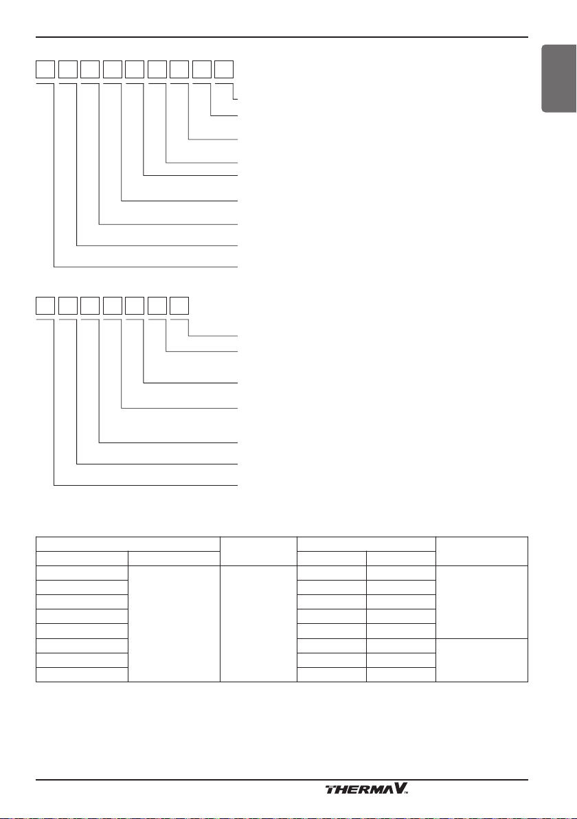
Model Information
Model number nomenclature
Factory Model Name
A H N W 1 6 6 0 6 B 0
Series Number
Function
B: DHW tank inegrated with Buffer tank
D: DHW tank integrated
Heater Capacity
06 : 6 kW
Heater Electrical ratings
6 : 1 phase 220-240 V AC 50 Hz
Heating Capacity
16 : 16 kW
Model Type
W : Inverter Heat Pump H : Heat Pump
Classification
N : Indoor Unit
Air-to-Water Heat Pump for R410A
A HUW 0 9 6 A 3
12 Air-to-Water Heat Pump
Series number
Function
A : General heating heat pump
Electrical ratings
6 : 1 phase 220-240 V AC 50 Hz 8 : 3 phase 380-415 V AC 50 Hz
Heating Capacity
09 : 9 kW 12 : 12 kW
14 : 14 kW 16 : 16 kW
Model Type
W : Inverter Heat Pump
Classification
U : Outdoor Unit
Air-to-Water Heat Pump for R410A
General Information
Buyer Model Name
H N161 6 T N B 0
H U09 1 U4 3
Series number
Platform (Chassis code)
B : DHW tank integrated
Classification
N : Indoor unit of Split type
T : DHW tank integrated
Heater capacity
6 : 6 kW Heater
Heater electrical ratings
1 : 1Ø, 220-240 V, 50 Hz
Heating capacity
Ex ) 16 kW : ‘16’
Classification
N : Indoor unit
H : Air to water Heat Pump
Series number
U3 : U3 Chassis
U4 : U4 Chassis
Classification
U : Outdoor unit of Split type
Electrical ratings
1 : 1Ø, 220-240 V AC 50 Hz
3 : 3Ø, 380-415 V AC 50 Hz
Heating capacity
Ex ) 9 kW : ‘09’
Classification
U : Outdoor unit
H : Air to water Heat Pump
ENGLISH
Model name and related information
Model Name
Outdoor Unit Indoor Unit Heating(kW)*1Cooling(kW)
Built-In Electric
Heater(kW)
AHUW146A2
AHUW096A3 9.0 9.0
AHUW126A3 12.0 10.4
AHUW146A3 14.0 11.0
AHUW166A3 16.0 12.0
AHNW16606B0
1Φ 4(2+2)
3Φ 6(2+2+2)
AHUW128A3 12.0 10.4
AHUW168A3 16.0 12.0
*1 : tested under Eurovent Heating condition
(water temperature 30 °C ’ 35 °C at outdoor ambient temperature 7 °C / 6 °C)
*2 : tested under Eurovent Cooling condition
(water temperature 23 °C ’ 18 °C at outdoor ambient temperature 35 °C / 24 °C)
Capacity
*2
14.0 11.0
Installation Manual 13
Power Source
220-240 V ~ 50 Hz
380-415 V ~ 50 HzAHUW148A3 14.0 11.0
General Information
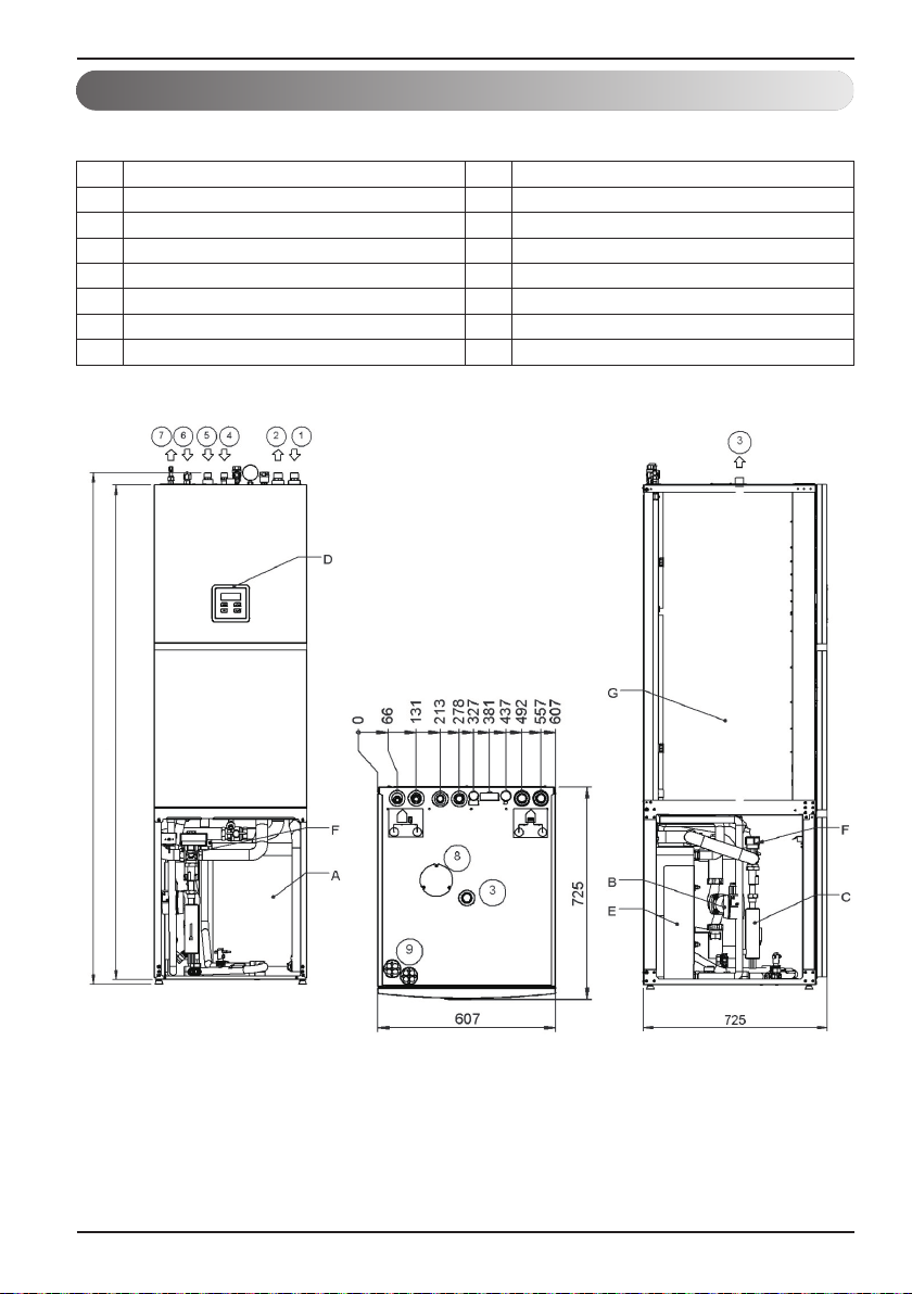
Parts and Dimensions
Indoor unit
1 Heating/Cooling Inlet A Buffer tank
2 Heating/Cooling Outlet B Circulating pump
3 Warm sanitary water C Electric flow heater
4 DHW - circulation D TT3000 Controller
5 Cold sanitary water - supply E Condenser
6 Gas pipe 5/8‘‘– refrigerant F 3 Way Valve
7 Liquid pipe 3/8‘‘– refrigerant G DHW tank
8 Mg. Anode
(unit:mm)
2 045
1 978
14 Air-to-Water Heat Pump
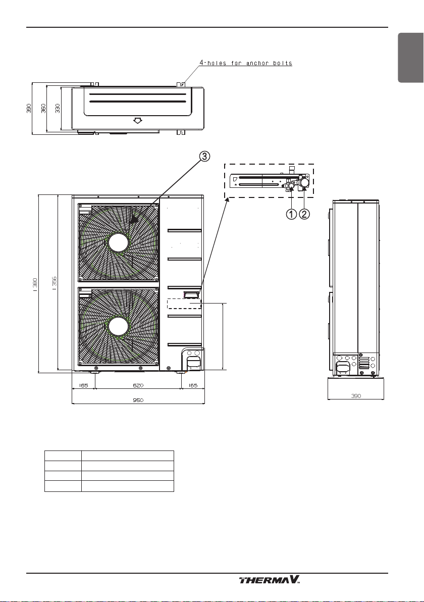
General Information
Outdoor unit(External)
ENGLISH
Product Heating
Capacity :
12 kW,14 kW,16 kW
(unit:mm)
Supporter
Description
No Name
1
Liquid-side Service Valve
2
Gas-side Service Valve
3
Air discharge Grill
490
Installation Manual 15
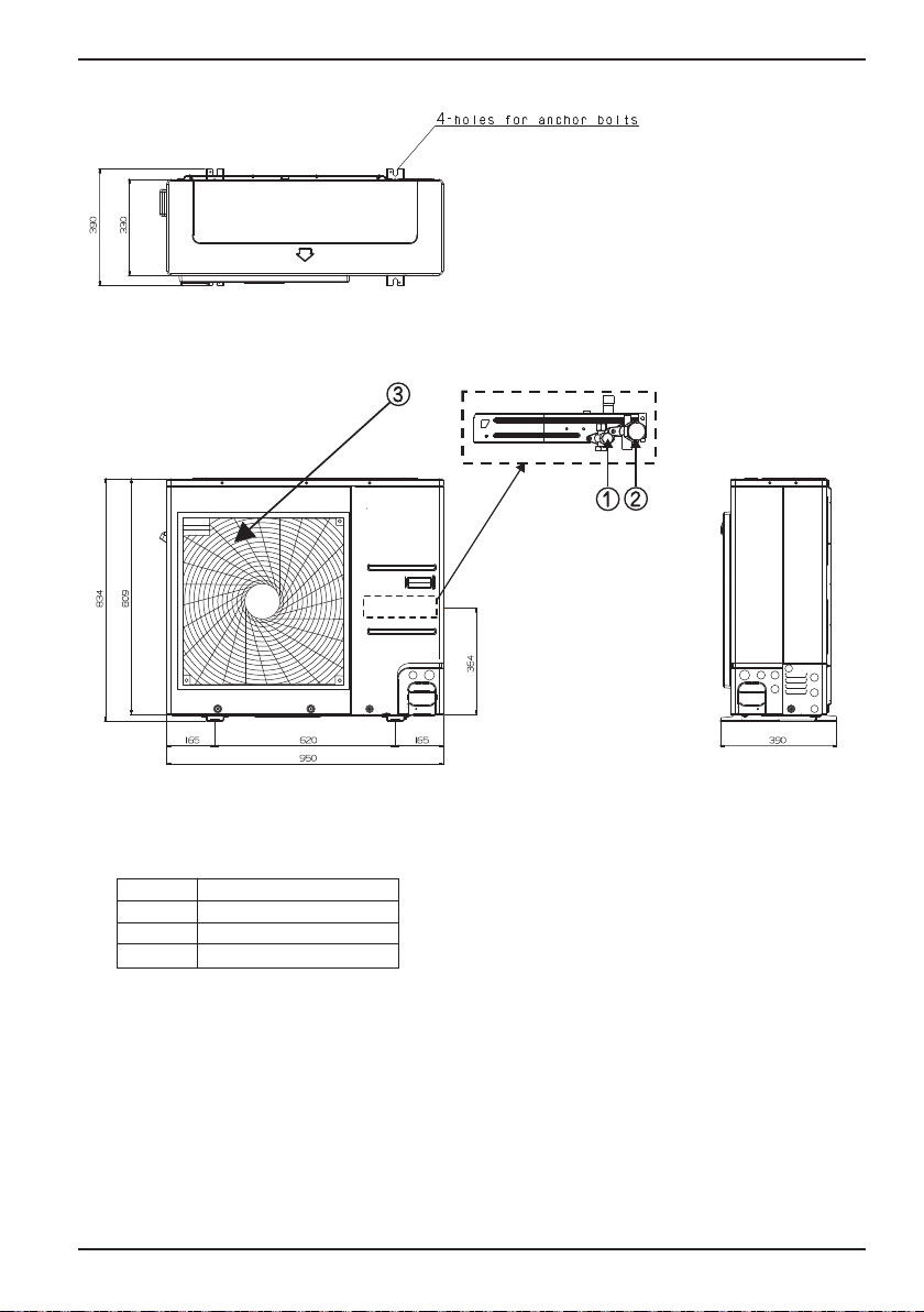
General Information
Product Heating
Capacity : 9 kW
(unit:mm)
Supporter
Description
No Name
1
Liquid-side Service Valve
2
Gas-side Service Valve
3
Air discharge Grill
16 Air-to-Water Heat Pump

Installation of Outdoor Unit
300
Fence or
obstacles
700
300
600
Sunroof
ENGLISH
Installation of Outdoor Unit
The outdoor unit of is installed outside to exchange heat with ambient air. Therefore, it
is important to properly secure the outdoor unit against harsh environmental conditions and
mechanical injuries. This chapter provides instructions to install the outdoor unit, make a route to
connect with the indoor, and precautionary measures to follow if installed around seaside.
Conditions where Outdoor Unit is Installed
• If a sunroof is built over the unit to prevent direct sunlight or rain exposure, make sure that heat
radiation from the heat exchanger is not restricted.
• Ensure that the spaces indicated by arrows around front, back and side of the unit.
• Do not place animals and plants in the path of the warm air.
• Consider weight of the outdoor unit into account and select a place where noise and vibration are
minimum.
• Select a place such that the warm air and noise from the outdoor unit do not disturb neighbors.
Minimum service space (unit:mm)
Installation Manual 17
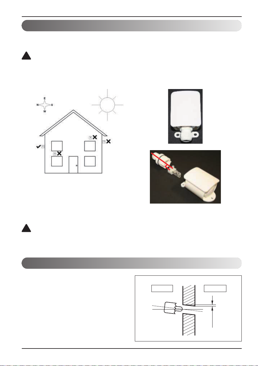
Installation of Outdoor Unit
Temperature sensor for external temperature.
The direction of connecting cables.
Set up and connection of the external sensor
For controlling heating according to the external temperature, it is necessary to install the external
temperature sensor.
CAUTION
!
The sensor must be set up in a shady spot.
The sensor must not be set up above a window or door. It must be located away from heat
sources.
For measuring external temperature, the sensor type PT 1000 is used.
T Temperature sensor for external temperature.
CAUTION
!
The external sensor must be connected and should be watertight to prevent water penetration.
Drill a Hole in the Wall
• For drilling a hole into the wall to connect a pipe
to connect pipe between the indoor unit and the
outdoor unit, please follow the below
instructions.
- Drill the piping hole with a Ø 70 mm hole core
drill.
- Piping hole should be slightly tilted to the
outdoor side to prevent raindrops from
entering indoors.
18 Air-to-Water Heat Pump
Indoor Outdoor
Wall
5~7 mm
Installation of Outdoor Unit
Sea wind Sea wind
Sea wind
Windbreak
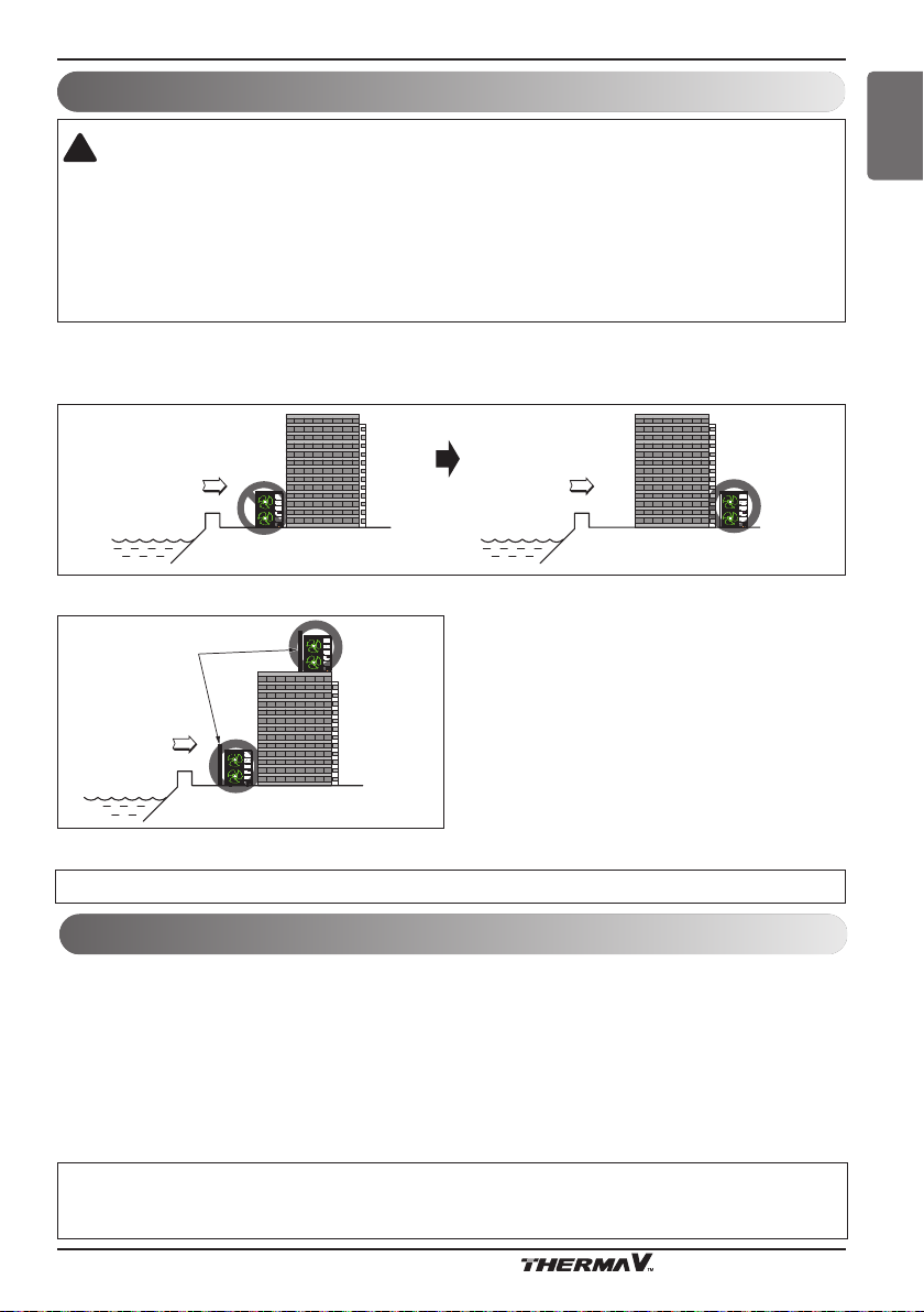
Installation at Seaside
CAUTION
!
1. Air conditioners should not be installed in areas where corrosive gases, such as acid or alkaline gas, are
produced.
2. Do not install the product where it could be exposed to sea breezes directly. It can result in corrosion on
the product. Corrosion, particularly on the condenser and evaporator fins, could cause product malfunction
or inefficient performance.
3. If outdoor unit is installed close to the seaside, it should avoid direct exposure to the sea breezes.
Otherwise it needs additional anticorrosion treatment on the heat exchanger.
ENGLISH
Selecting the location(Outdoor Unit)
1) If the outdoor unit is to be installed close to the seaside, direct exposure to the sea breezes should be
avoided. Install the outdoor unit on the opposite side of the direction of the sea breeze.
2) In case, to install the outdoor unit on the seaside, put up a windbreak not to be exposed to the sea wind.
• It should be strong enough like concrete to prevent
the sea wind from the sea.
• The height and width should be more than 150 % of
the outdoor unit.
• It should be kept more than 700 mm of space
between outdoor unit and the windbreak for easy
air flow.
.
3) Select a well-drained place.
Periodic ( more than once/a year ) clean the impurities settled on the heat exchanger by using water.
Seasonal wind and cautions in winter
• Sufficient measures are required in a frozen area or chilly climates to facilitate efficient operation of the product.
• Take preemptive measures in case there is a seasonal wind or snow in winter.
• Install a suction and discharge duct not to let in snow or rain.
• Install the outdoor unit such that it does not come in contact with snow directly. If snow piles up and freezes on the air
suction hole, the system may malfunction. If it is installed in a snowy area, attach the hood to the system.
• Install the outdoor unit at the installation console higher by 500 mm than the average snowfall (annual average snowfall)
if it is installed at the area with heavy snowfall.
• Where snow is accumulated on the upper part of the Outdoor Unit by more than 100 mm, always remove the snow for
efficient operation.
1. The height of H frame must be more than 2 times the snowfall and its width shall not exceed the width of the
product. (If width of the frame is wider than that of the product, snow may accumulate)
2. Don't install the suction hole and discharge hole of the Outdoor Unit facing the seasonal wind.
Installation Manual 19
Installation of Indoor Unit
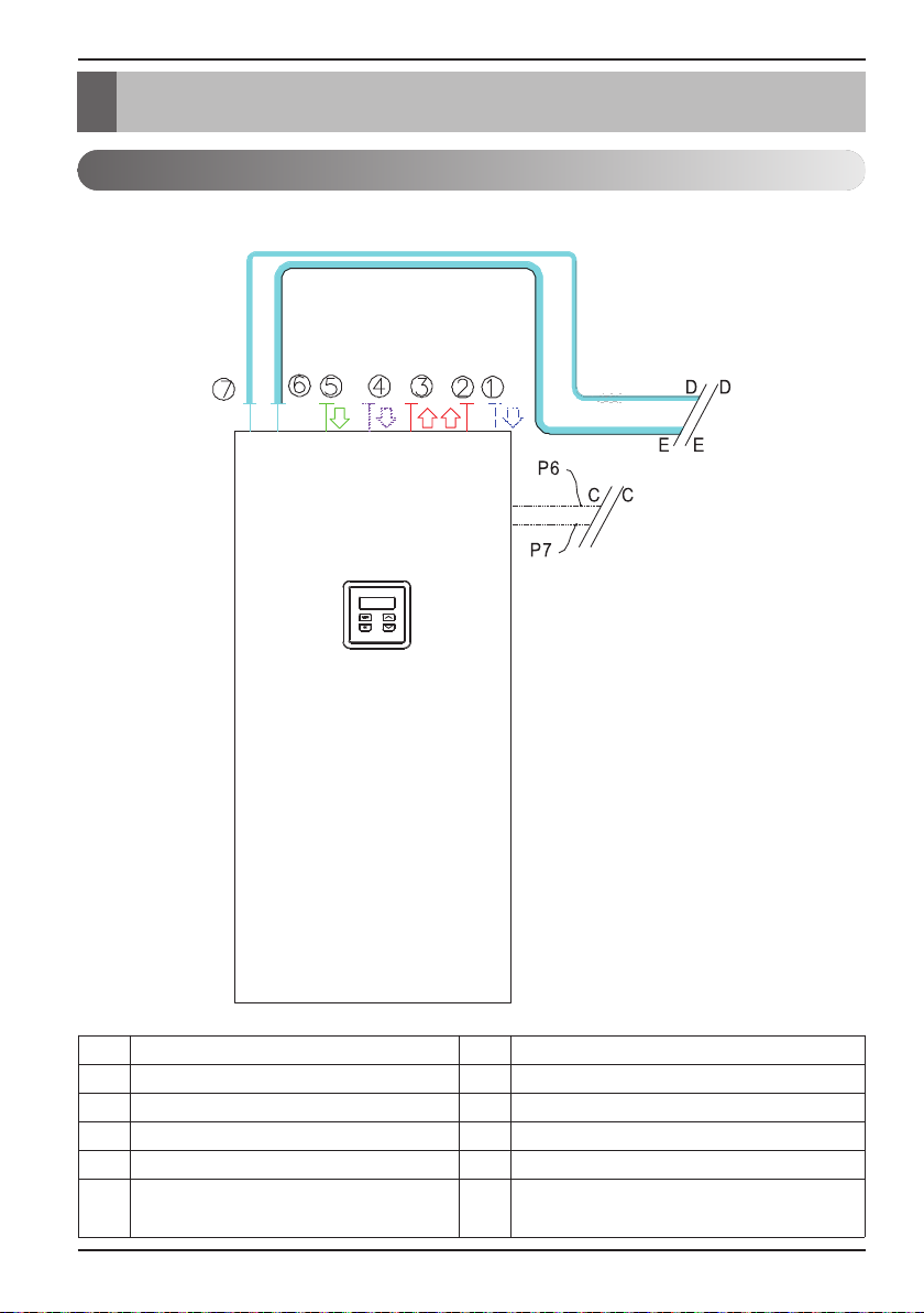
Installation of Indoor Unit
General
The device is installed according to capacity
1 Heating/Cooling Inlet 3 DHW – outlet
2 Heating/Cooling Outlet 4 DHW – circulation
C Electrical and communication connection 5 DHW – inlet
E Connection to outdoor unit 6 Gas pipe 5/8‘‘– refrigerant
D Connection to outdoor unit 7 Liquid pipe 3/8‘‘– refrigerant
P6 Power supply cable P7
20 Air-to-Water Heat Pump
Communication cable - connection between
outdoor and indoor unit
Installation of Indoor Unit
Location of the device
ENGLISH
NOTICE
• It is obligatory to consider the minimal clearance from obstacles for ensuring unobstructed access
for maintenance and service.
• The location of the device has to be accessible by manual transport devices to ensure
undisturbed delivery of replacement parts and equipment for maintenance and servicing.
The operator is charged costs connected with hiring special equipment for installing the device,
servicing and maintenance separately, these costs are not subjected to warranty.
• When you install a device into the building, ensure that you build in a water drain in case of
spillage.
Minimal clearance from the device
CAUTION
!
The device must not be installed under pipelines because there is a possibility of condensate
forming. Ingress of water condensate can cause disturbances in the operation.
NOTICE
The installation location of the indoor unit must be dry and in the temperature range between
+10 °C and 40 °C.
Installation Manual 21
 Loading...