

Page 1

1 | P a g e
AHU Conversion Kit Application Guide
Page 2

2 | P a g e
Proprietary Data Notice
This document, as well as all reports, illustrations, data, information, and other materials are the property of LG
Electronics U.S.A., Inc., and are disclosed by LG Electronics U.S.A., Inc., only in confidence.
Note: Legal Disclaimer: All material provided herein is for
informational or educational purposes only. It is not
intended to be a substitute for professional advice. Please
consult with your engineer or design professionals for
application to your system.
For continual product development, LG Electronics U.S.A., Inc.,
reserves the right to change specifications without notice.
For more technical materials such as submittals, engineering manuals, and catalogs, visit www.lghvac.com.
This document, as well as all reports, illustrations, data, information, and other materials are the property of LG Electronics U.S.A., Inc.
©LG Electronics U.S.A., Inc.
VRF-WP-AH-001-US1018
Due to our policy of continuous product innovation, some specifications may change without notification
©LG Electronics U.S.A., Inc., Englewood Cliffs, NJ. All rights reserved. “LG” is a registered trademark of LG Corp.
Page 3

3 | P a g e
Contents
Proprietary Data Notice .....................................................................................................................2
Why use LG's AHU Conversion Kit? .....................................................................................................6
Energy Saving: LG vs. the Rest .................................................................................................................. 6
3rd Party Support ...................................................................................................................................... 7
Large Piping Distance ................................................................................................................................ 9
Definitions ....................................................................................................................................... 10
Components and Features: EEV Kits.................................................................................................. 11
PRLK048A0 .............................................................................................................................................. 11
PRLK096A0 .............................................................................................................................................. 12
PRLK396A0 .............................................................................................................................................. 13
PRLK594A0 .............................................................................................................................................. 14
Outdoor Unit + EEV Kit Combinations .................................................................................................... 15
Recommended 3rd Party Coil Volume ..................................................................................................... 16
Components and Features: Communication Kits ............................................................................... 17
PAHCMR000 ............................................................................................................................................ 17
PAHCMS000 ............................................................................................................................................ 19
Communication Kit Features .................................................................................................................. 21
DIP Switch: Communication Kits ....................................................................................................... 22
DIP Switch Settings – PAHCMR000 ......................................................................................................... 22
DIP Switch Applications with Thermostats – PAHCMR000 ..................................................................... 25
DIP Switch Settings – PAHCMS000 ......................................................................................................... 27
DIP Switch Application with Thermostats – PAHCMS000 ....................................................................... 29
Comm Kit Combinations ................................................................................................................... 31
Combination Options .............................................................................................................................. 31
EEV Kit Combinations ....................................................................................................................... 32
1:1 Combination ...................................................................................................................................... 32
1:2 Combination ...................................................................................................................................... 32
PRLK048/096A0 + PRLK396/594A0 Combination – Not Possible ........................................................... 33
PRLK594A0 + PRLK594A0 Combination – Not Possible .......................................................................... 34
PRLK396A0 + PRLK594A0 Combination – Not Possible .......................................................................... 34
VRF-WP-AH-001-US1018
Due to our policy of continuous product innovation, some specifications may change without notification
©LG Electronics U.S.A., Inc., Englewood Cliffs, NJ. All rights reserved. “LG” is a registered trademark of LG Corp.
Page 4

4 | P a g e
EEV + IDU Combination – Not Possible ................................................................................................... 35
EEV Kit Combination Ratio ...................................................................................................................... 35
Application Cases for Communication Kits ........................................................................................ 36
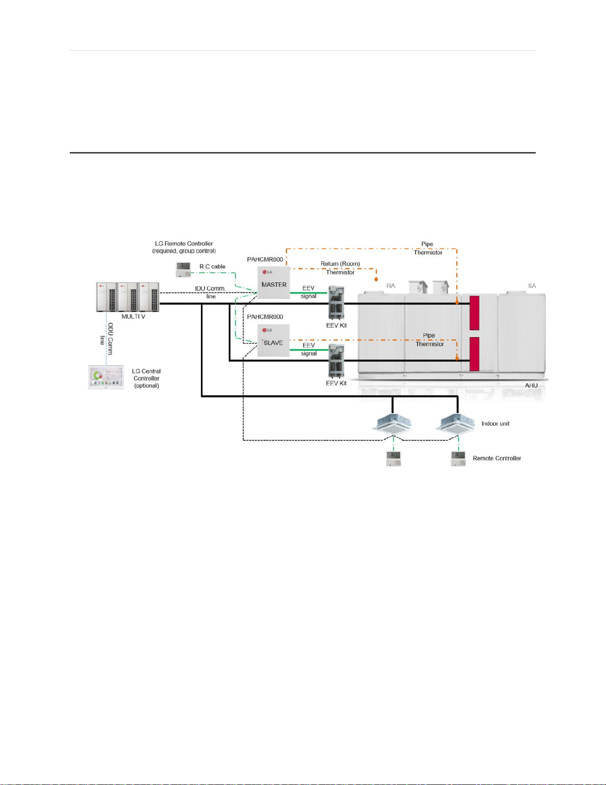
Return Air Control – 1-ODU System + 1 AHU (1 coil) + Controls ............................................................ 36
Return Air Control – 1-ODU System + 1 AHU (2 coil) + Controls ............................................................ 37
Return Air Control – 1-ODU System + 1 AHU (1 coil) + IDU + Controls .................................................. 38
Return Air Control – 1-ODU System + 1 AHU (2 coil) + IDU + Controls .................................................. 39
Return Air Control – 1-ODU System + Multiple AHU’s + Controls .......................................................... 40
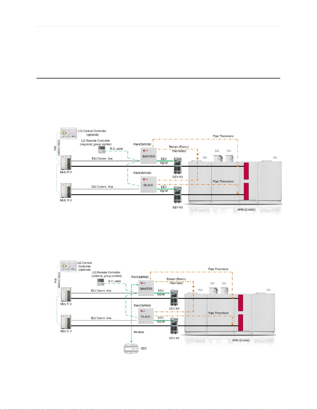
Return Air Control – 2-ODU System + 1 AHU (2 coils) + Controls ........................................................... 42
Supply Air Control – 1-ODU System + 1 AHU (1 coils) + Controls ........................................................... 43
Supply Air Control – 1-ODU System + 1 AHU (2 coils) + Controls ........................................................... 44
Supply Air Control – 1-ODU System + Multiple AHU’s ............................................................................ 45
Supply Air Control – 1-ODU System + 1 AHU (1 coil) + IDU’s .................................................................. 46
Supply Air Control – 1-ODU System + 1 AHU (2 coils) + IDU’s ................................................................ 47
Supply Air Control – 2-ODU System + 1 AHU (2 coils) ............................................................................ 48
Supply Air Control – 1-ODU System + 1 AHU (2 coils) + I/O Module + DDC Control .............................. 49
Example AHU Kit for Large AHU ........................................................................................................ 51
Components Required ............................................................................................................................ 51
Selecting in LATS HVAC ........................................................................................................................... 51
Application Types .................................................................................................................................... 55
Application Examples .............................................................................................................................. 57
Office Building ..................................................................................................................................... 57
AHU Conversion Kit for Small AHU.................................................................................................... 58
Components Required ............................................................................................................................ 58
Selecting in LATS HVAC ........................................................................................................................... 58
Application Types .................................................................................................................................... 62
Application Examples .............................................................................................................................. 63
Restaurant ........................................................................................................................................... 63
Elementary/High School ..................................................................................................................... 64
Coil Design Parameters .................................................................................................................... 65
AHU Module – Design Tips (Do’s) ........................................................................................................... 65
VRF-WP-AH-001-US1018
Due to our policy of continuous product innovation, some specifications may change without notification
©LG Electronics U.S.A., Inc., Englewood Cliffs, NJ. All rights reserved. “LG” is a registered trademark of LG Corp.
Page 5

5 | P a g e
AHU Module – Design Tips (Dont’s) ........................................................................................................ 66
AHU Module DX Coil Sizing Parameters – Cooling .................................................................................. 66
AHU Module DX Coil Sizing Parameters – Heating ................................................................................. 67
Circuit Diagram ................................................................................................................................ 68
Supply Air Communication Kit - PAHCMS000 ......................................................................................... 68
Return Air Communication Kit - PAHCMR000 ........................................................................................ 69
VRF-WP-AH-001-US1018
Due to our policy of continuous product innovation, some specifications may change without notification
©LG Electronics U.S.A., Inc., Englewood Cliffs, NJ. All rights reserved. “LG” is a registered trademark of LG Corp.
Page 6
6 | P a g e
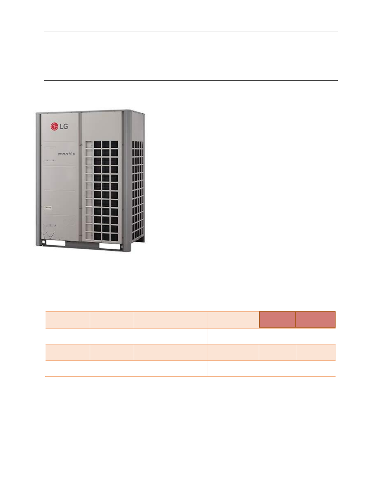
Brand
Series
Model #
Capacity
EER
IEER
LG
Multi V5
ARUM121BTE5
10 tons
Carrier
Gemini
38AUQA12A0B5-0A0A0
10 tons
11
12
Trane
Precedent
YSC120ED
10 tons
9.5
10.97
York
Predator
XP120
10 tons
11
12.4
Information taken from Carrier’s Product Page: http://www.carrierenterprise.com/carrier-10-ton-heat-pump-condensing-unit-with-puron-refrigerant-38auqa12a0b5-0a0a0
Information taken from Trane’s Product Page: https://www.trane.com/commercial/north-america/us/en/products-systems/equipment/unitary/rooftop-systems/precedent-3-to-10-tons.html
Information taken from York’s Product Page: http://www.york.com/for-your-workplace/packaged-and-split-dx-systems/packaged-heat-pumps/xp-predator
LG's AHU Conversion Kit can offer energy savi ngs over
conventional condensing units used with DX split system s. It
allows connection of an LG Multi V inverter co mpressor
condensing u nits to any third party AHU .
Compared to other convent ional condensin g units, LG's Multi
V5 unit has a higher EE R rating and almost twice the IEER
rating as the c ompetitors below.
1
1
2 3
2
3
24.6
12.5
Why use LG's AHU Conversion Kit?
Energy Saving: LG vs. the Rest
VRF-WP-AH-001-US1018
Due to our policy of continuous product innovation, some specifications may change without notification
©LG Electronics U.S.A., Inc., Englewood Cliffs, NJ. All rights reserved. “LG” is a registered trademark of LG Corp.
Page 7
7 | P a g e
Versatile: Allo ws for any air handling unit to
connect with L G's outdoor units
Combination with 3rd Party AHU
Comm. Kit
PAHCMR000
PAHCMS000
EEV Kit
PRLK048A0
PRLK096A0
PRLK396A0
PRLK594A0
3rd Party Support
VRF-WP-AH-001-US1018
Due to our policy of continuous product innovation, some specifications may change without notification
©LG Electronics U.S.A., Inc., Englewood Cliffs, NJ. All rights reserved. “LG” is a registered trademark of LG Corp.
Page 8

8 | P a g e
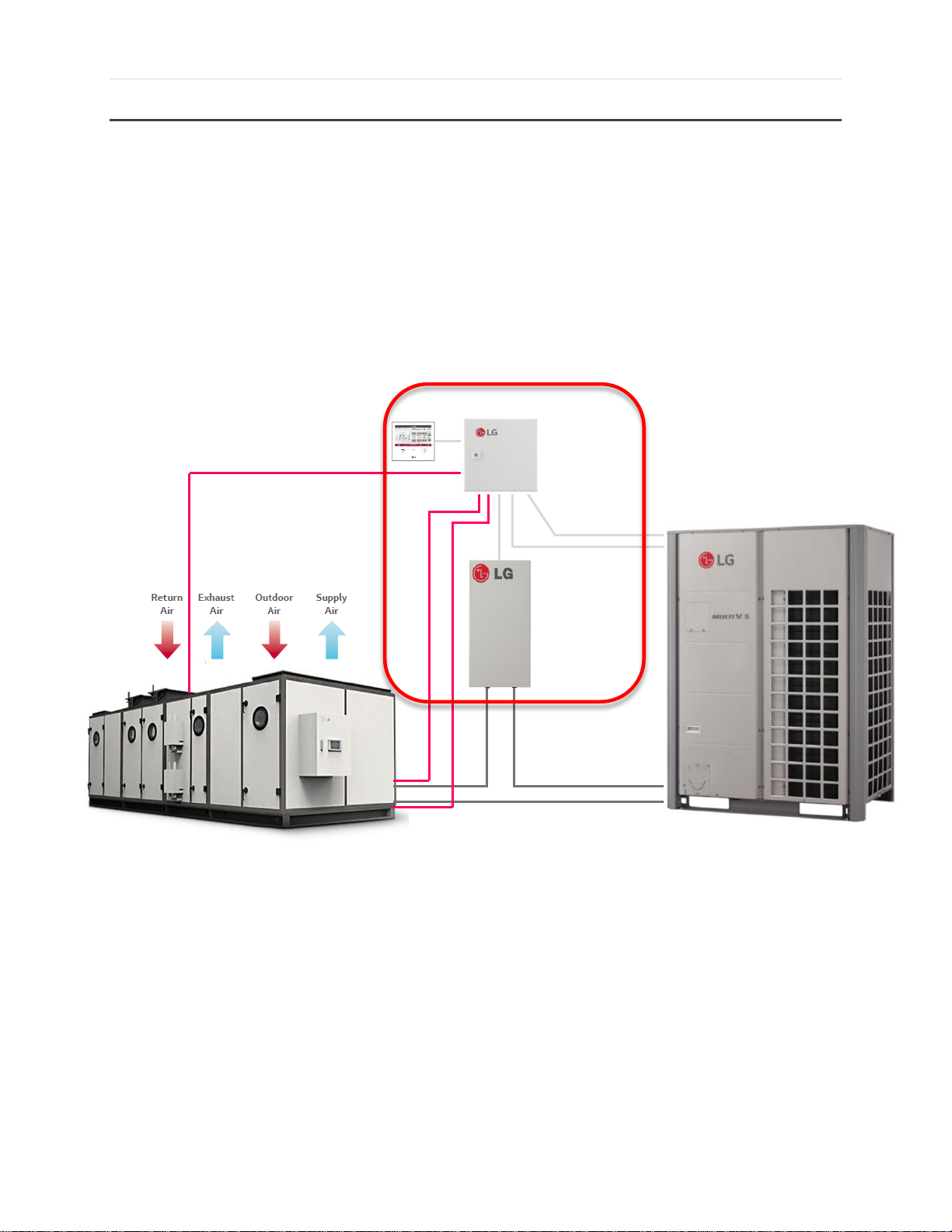
The AHU Conversion Kit also allows com munication
between the AHU and LG's VRF Systems.
AHU Conversion Kit
Refrigerant pipe
Refrigerant pipe
OA Duct
LG Wired Controller
LG VM3 Controller
LG VM3 Controller
VRF-WP-AH-001-US1018
Due to our policy of continuous product innovation, some specifications may change without notification
©LG Electronics U.S.A., Inc., Englewood Cliffs, NJ. All rights reserved. “LG” is a registered trademark of LG Corp.
Page 9
9 | P a g e
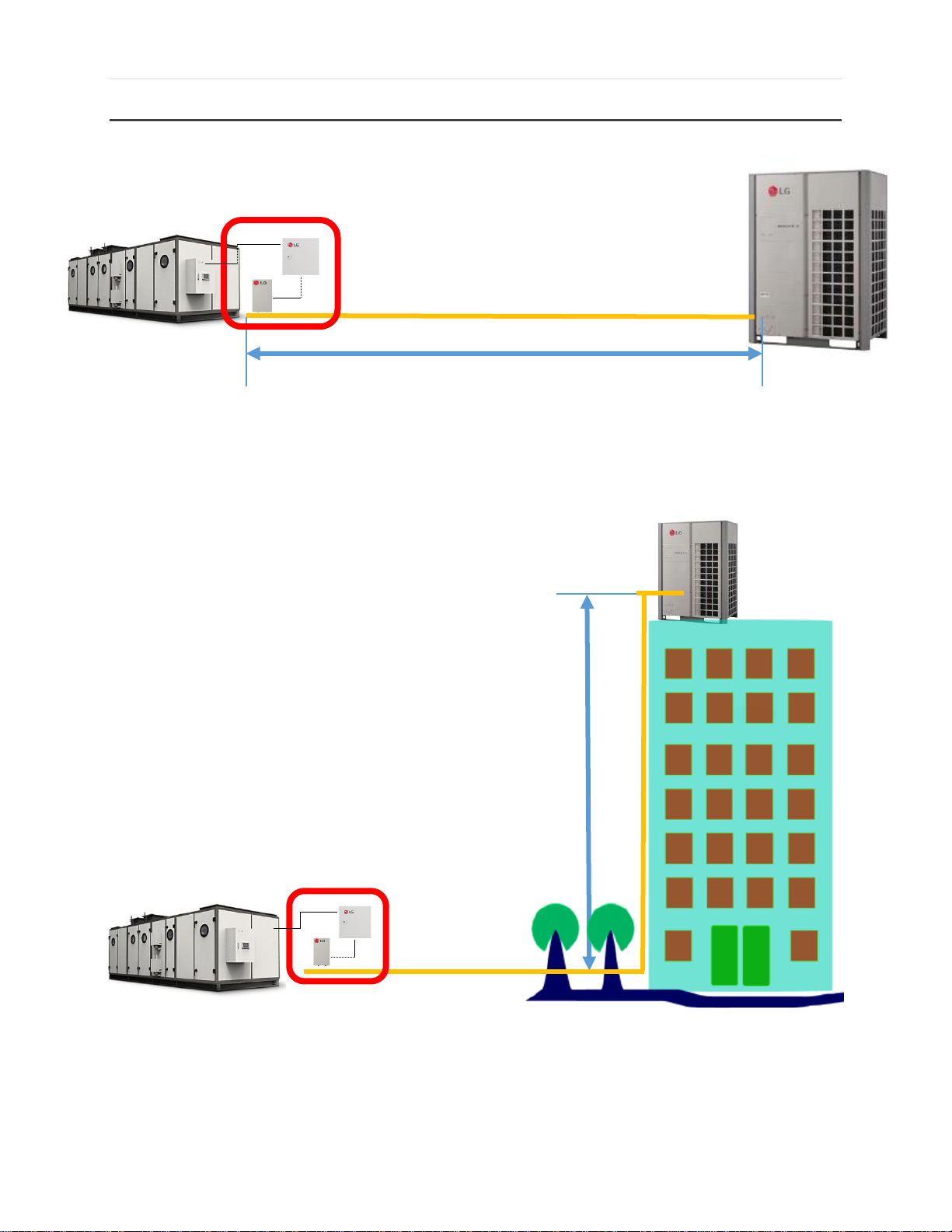
Or… vertically piped as far as 360 fee t.
Allows for the Outdoor Unit to be
horizontally piped as far as 656 actual feet
away from the AHU
360 feet
656 feet
AHU Conversion Kit
AHU Conversion Kit
Large Piping Distance
VRF-WP-AH-001-US1018
Due to our policy of continuous product innovation, some specifications may change without notification
©LG Electronics U.S.A., Inc., Englewood Cliffs, NJ. All rights reserved. “LG” is a registered trademark of LG Corp.
Page 10

10 | P a g e
Definitions
EEV Kit - Models PRLK048A0, PRLK096A, PRLK396A0 and PRLK594A0
Communication Kit (Return Air) - Model PAHCMR000
Communication Kit (Supply Air) - Model PAHCMS000
AHU Conversion Kit - Consists of an EEV Kit and a Communication Kit
VRF-WP-AH-001-US1018
Due to our policy of continuous product innovation, some specifications may change without notification
©LG Electronics U.S.A., Inc., Englewood Cliffs, NJ. All rights reserved. “LG” is a registered trademark of LG Corp.
Page 11

11 | P a g e
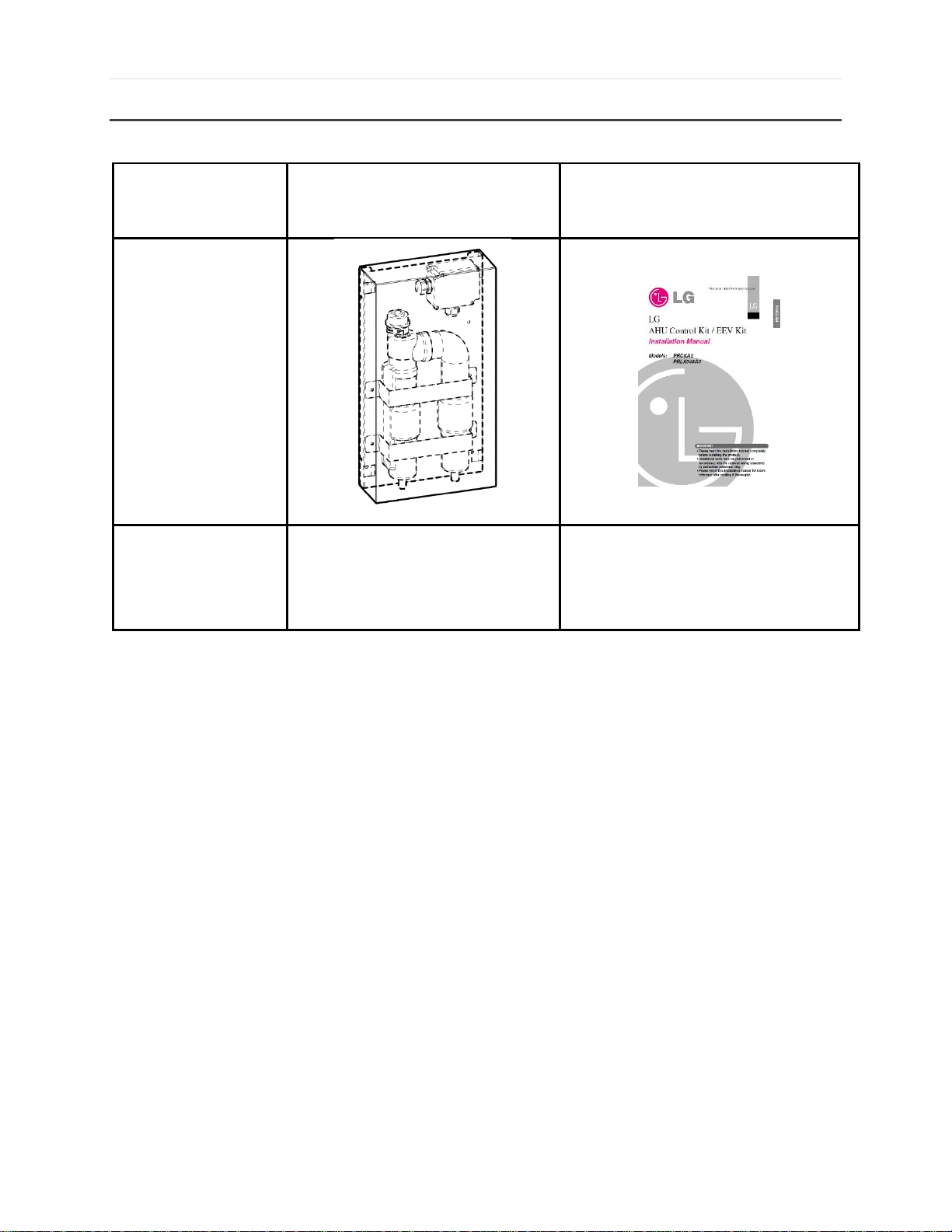
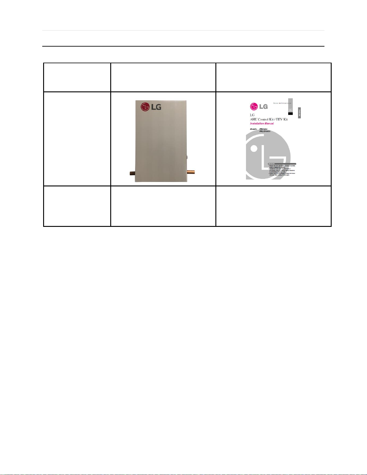
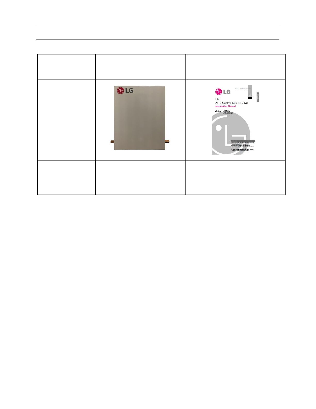
Components:
EEV Kit
Installation Manual
Shape:
Quantity (EA):
1
1
Components and Features: EEV Kits
PRLK048A0
Standard Features:
VRF-WP-AH-001-US1018
Figure 1. PRLK048A0 EEV Kit Contents
Max Ton Capacity: 8 Tons
Btu Capacity: 12 – 96 kBtu/h
System Compatibility: Heat Pump or Heat Recovery
Controls refrigerant flow between Multi V air or water source units and a 3rd party AHU
Minimum coil entering air temperature in heating mode is 41°F
Maximum distance between EEV and Comm. kit is 32 feet
Maximum of (1) EEV kit can be connected to Comm. kit
Designed for indoor installations (field supplied water‐proof enclosure must be used
when installing outdoors)
Due to our policy of continuous product innovation, some specifications may change without notification
©LG Electronics U.S.A., Inc., Englewood Cliffs, NJ. All rights reserved. “LG” is a registered trademark of LG Corp.
Page 12
12 | P a g e
Components:
EEV Kit
Installation Manual
Shape:
Quantity (EA):
1
1
PRLK096A0
Standard Features:
Max Ton Capacity: 16 Tons
Btu Capacity: 115 – 192 kBtu/h
System Compatibility: Heat Pump only
Controls refrigerant flow between Multi V air or water source units and a 3rd party air
handling unit.
Minimum coil entering air temperature in heating mode is 41°F
Maximum distance between EEV and Comm. kit is 32 feet
Maximum of (1) EEV kit can be connected to Comm. kit
Designed for indoor installations (field supplied water‐proof enclosure must be used
when installing outdoors)
Figure 2. PRLK096A0 EEV Kit Contents
VRF-WP-AH-001-US1018
Due to our policy of continuous product innovation, some specifications may change without notification
©LG Electronics U.S.A., Inc., Englewood Cliffs, NJ. All rights reserved. “LG” is a registered trademark of LG Corp.
Page 13
13 | P a g e
Components:
EEV Kit
Installation Manual
Shape:
Quantity (EA):
1
1
PRLK396A0
Figure 3. PRLK396A0 EEV Kit Contents
Standard Features:
Max Ton Capacity: 32 Tons
Btu Capacity: 216 – 384 kBtu/h
System Compatibility: Heat Pump only
Controls refrigerant flow between Multi V air or water source units and a 3rd party air
handling unit
Minimum coil entering air temperature in heating mode is 41°F
Maximum distance between EEV and Comm. kit is 32 feet
Maximum of (1) EEV kit can be connected to Comm. kit
Designed for indoor installations (field supplied water‐proof enclosure must be used
when installing outdoors)
VRF-WP-AH-001-US1018
Due to our policy of continuous product innovation, some specifications may change without notification
©LG Electronics U.S.A., Inc., Englewood Cliffs, NJ. All rights reserved. “LG” is a registered trademark of LG Corp.
Page 14
14 | P a g e
Components:
EEV Kit
Installation Manual
Shape:
Quantity (EA):
1
1
PRLK594A0
Figure 4. PRLK594A0 EEV Kit Contents
Standard Features:
Max Ton Capacity: 48 Tons
Btu Capacity: 408 - 576 kBtu/h
System Compatibility: Heat Pump only with PAHCMS000 (requires EEV module)
Controls refrigerant flow between Multi V air or water source units and a 3rd party air
handling unit
Minimum coil entering air temperature in heating mode is 41°F
Maximum distance between EEV and Comm. kit is 32 feet
Maximum of (1) EEV kit can be connected to Comm. kit
Designed for indoor installations (field supplied water‐proof enclosure must be used
when installing outdoors)
VRF-WP-AH-001-US1018
Due to our policy of continuous product innovation, some specifications may change without notification
©LG Electronics U.S.A., Inc., Englewood Cliffs, NJ. All rights reserved. “LG” is a registered trademark of LG Corp.
Page 15

15 | P a g e
EEV Kit
EEV Kit
MULTI V
Outdoor Unit + EEV Kit Combinations
1 Multi V + multiple EEV Kits
Multiple Multi V’s + multiple EEV Kits
Single Split does not require expansion valves
Basic rule: 1 DX coil required 1 Expansion Valve
VRF-WP-AH-001-US1018
Due to our policy of continuous product innovation, some specifications may change without notification
©LG Electronics U.S.A., Inc., Englewood Cliffs, NJ. All rights reserved. “LG” is a registered trademark of LG Corp.
Page 16
16 | P a g e
EEV Model
Capacity
(kBTU/h)
Recommended 3rd Party Coil Volume
MIN (in.3)
MAX (in.3)
PRLK048A0
12
67.1
234.9
15
85.4
299.0
18
109.8
384.4
24
134.3
469.9
28
164.8
576.7
36
189.2
662.1
42
207.5
726.2
48
244.1
854.3
54
250.2
875.7
76
329.5
1,153.3
96
384.4
1,345.6
PRLK096A0
115
445.5
1,559.2
134
518.7
1,815.5
153
567.5
1,986.3
172
640.7
2,242.6
192
683.5
2,392.1
PRLK396A0
216
768.9
2,691.1
240
854.3
2,990.2
264
939.8
3,289.2
288
1,025.2
3,588.2
312
1,110.6
3,887.2
336
1,196.1
4,186.2
360
1,281.5
4,485.2
384
1,366.9
4,784.3
PRLK594A0
408
1,452.4
5,083.3
432
1,543.9
5,403.6
456
1,623.2
5,681.3
480
1,708.7
5,980.3
504
1,800.2
6,300.7
528
1,879.5
6,578.4
552
1,971.1
6,898.7
576
2,050.4
7,176.4
Recommended 3rd Party Coil Volume
Table 1. Recommended 3rd Party Coil Volume
VRF-WP-AH-001-US1018
Due to our policy of continuous product innovation, some specifications may change without notification
©LG Electronics U.S.A., Inc., Englewood Cliffs, NJ. All rights reserved. “LG” is a registered trademark of LG Corp.
Page 17
17 | P a g e
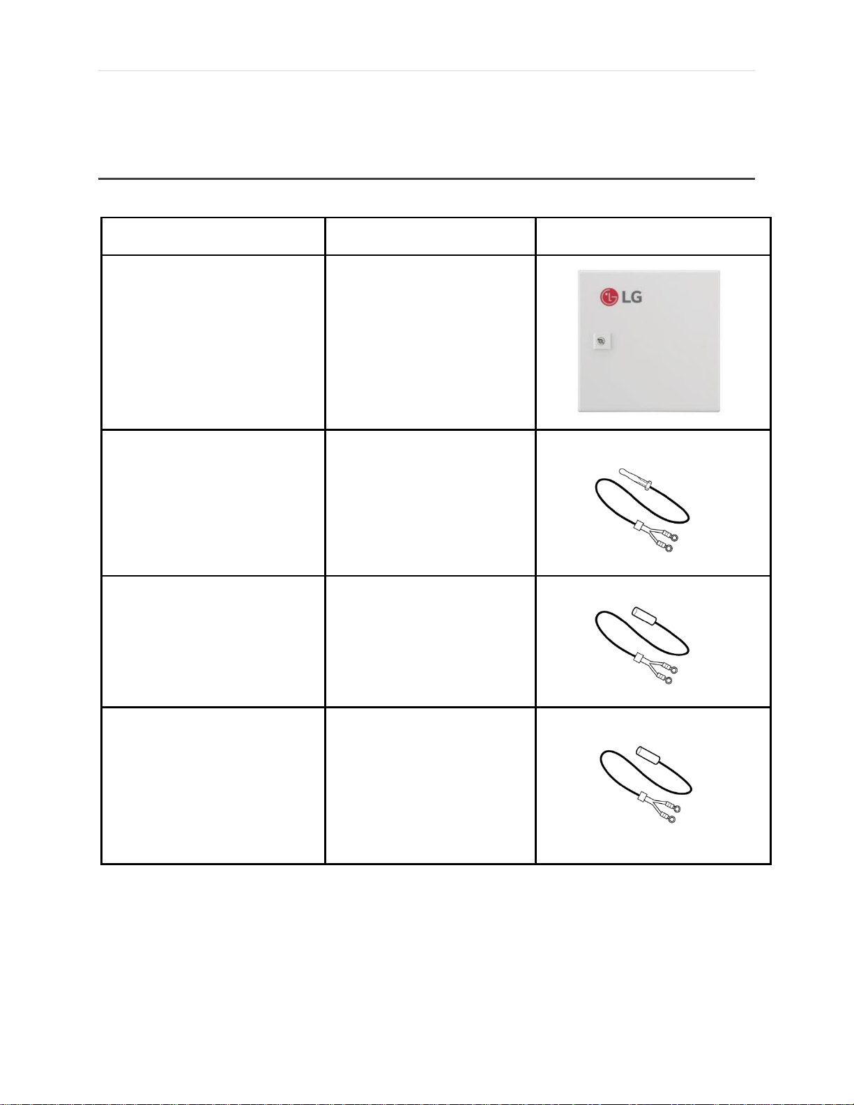
Part
Quantity
Image
Communication Kit - Return Air
One (1)
Return Air (Room) Thermistor
One (1)
Pipe Out Thermistor
One (1)
Pipe In Thermistor
One (1)
Components and Features: Communication Kits
PAHCMR000
VRF-WP-AH-001-US1018
©LG Electronics U.S.A., Inc., Englewood Cliffs, NJ. All rights reserved. “LG” is a registered trademark of LG Corp.
Due to our policy of continuous product innovation, some specifications may change without notification
Page 18

18 | P a g e
Bracket
One (1)
Controller Assembly (Comm. PCB)
One (1)
Figure 5. PAHCMR000 Contents
Standard Features:
Function: Allows communication between third-party air handling units and LG air
source and water source units
Can connect with multiple AHU’s with indoor units
Control Options: LG Wired Controller (required for LG controls), LG Central Controller,
3rd Party AHU Controller
System Compatibility: Heat Recovery, Heat Pump
AHU Coil Capacities 12 – 384 kBtu/h for Multi V and 5-85 kBtu/h for Single Zone (41°F
minimum entering air temp)
3 Thermistors (Pipe in, pipe out, and return air. 16.4 ft. length each)
AHU Fan Control H/M/L
EEV Control
Designed for indoor installation (field-supplied waterproof enclosure required for
outdoor installation)
Can control 3 speed or single speed 3rd party fan motor (requires relays or motor
starter)
Requires 208-230 VAC, 1 phase power
VRF-WP-AH-001-US1018
Due to our policy of continuous product innovation, some specifications may change without notification
©LG Electronics U.S.A., Inc., Englewood Cliffs, NJ. All rights reserved. “LG” is a registered trademark of LG Corp.
Page 19

19 | P a g e
Part
Quantity
Image
Communication Kit - Supply Air
One (1)
Return Air (Room) Thermistor
One (1)
Pipe Out Thermistor
One (1)
Pipe In Thermistor
One (1)
PAHCMS000
VRF-WP-AH-001-US1018
©LG Electronics U.S.A., Inc., Englewood Cliffs, NJ. All rights reserved. “LG” is a registered trademark of LG Corp.
Due to our policy of continuous product innovation, some specifications may change without notification
Page 20

20 | P a g e
Bracket
One (1)
Harness, Multi
One (1)
Controller Assembly (Comm. PCB
and Main PCB)
One (1) Each
Standard Features:
Function: Allows communication between third-party air handling units and LG air
source and water source units
Can connect with one AHU (one DX Coil) and cannot connect with indoor units
Control Options: LG Wired Controller (required for LG Controls), LG Central Controller,
3rd Party AHU Controller
VRF-WP-AH-001-US1018
System Compatibility: Heat Pump
AHU Coil Capacities 12 – 594 kBtu/h for Multi V and 5 – 85 kBtu/h for Single Zone (41°F
minimum entering air temp)
3 Thermistors (Pipe in, pipe out, and return air. 16.4 ft. length each)
Due to our policy of continuous product innovation, some specifications may change without notification
©LG Electronics U.S.A., Inc., Englewood Cliffs, NJ. All rights reserved. “LG” is a registered trademark of LG Corp.
Figure 6. PAHCMS000 Contents
Page 21

21 | P a g e
DDC (3rd party)
Direct Control / Monitoring through
Dry Contact for Modbus
Dry Contact for Thermostat
Additional dry contacts are not required
EEV Kit
EEV Kit
EEV Kit
EEV Kit
EEV Control
Designed for indoor installation (field-supplied waterproof enclosure required for
outdoor installation)
Requires 208-230 VAC, 1 phase power
Communication Kit Features
Dry contact function is embedded in the communication kits
Modbus Communication is possible without applying extra devices
AI/DI/DO or Modbus Communication
Multiple DX coil installation is possible for discharge air control
VRF-WP-AH-001-US1018
Due to our policy of continuous product innovation, some specifications may change without notification
©LG Electronics U.S.A., Inc., Englewood Cliffs, NJ. All rights reserved. “LG” is a registered trademark of LG Corp.
Page 22
22 | P a g e
S/W name
No
Item
Setting
Note
SW1
1
ODU Type
On
Single Comm.
Using Single Split outdoor unit
Off
MULTI V Comm.
Using MULTI V outdoor unit
2
Control Type
On
Communication
Controlled by DDC through Modbus and LG centralized
controller
Off
Contact signal
Controlled by DDC through Contact signal (AI, DI)
LG Centralized controller can only monitor status
3
DO Type
On
Fan Speed
DO1 : High, DO2 : Middle, DO3 : Low
Off
Status
DO1 : On/Off, DO2 : Defrost, DO3 : Alarm
4
Fan Speed
(TH. On/Off)
On
Fixed
Fan Speed doesn’t change when TH. On/Off
(Cooling/Heating)
Off
Change
Fan Speed change to LOW when Th. Off in Cooling Mode
Fan Speed change to STOP when Th. Off in Heating
Mode
SW2
1
Reserved - -
-
2
Reserved - -
-
3/4
UI Setting
Off/Off
UI Setting #1
UI1 : Operation On/Off, UI2 : Heating/Cooling
UI3 : Forced Thermo On/Off, UI4 : Target air
temperature
Off/On
UI Setting #2
UI1 : Operation On/Off, UI2 : Cooling only/Off
UI3 : Heating only/Off, UI4 : Forced Thermo On and Off
On/Off
Reserved
-
On/On
Reserved
-
SW3
1
Master/Slave
On
Slave mode
Please see “9.3 Multiple module installation guide” in
the Installation Manual for more detail
Off
Master mode
Master mode is default for single AHU Controller
installation.
Please see “9.3 Multiple module installation guide” in
the Installation Manual for more detail
2/3
Off/Off
Heat Pump
Cooling or Heating operation mode is available
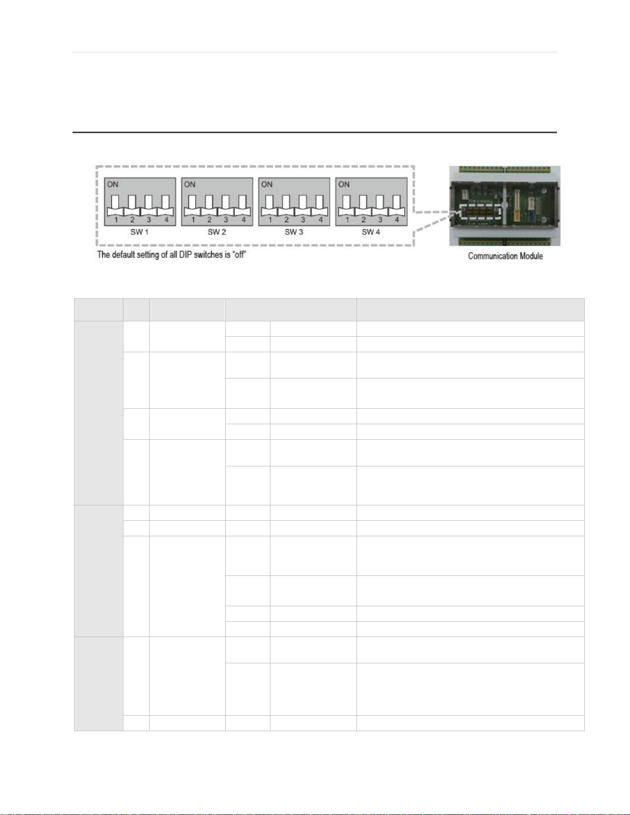
DIP Switch: Communication Kits
DIP Switch Settings – PAHCMR000
Figure 7. DIP Switch – PAHCMR000
VRF-WP-AH-001-US1018
©LG Electronics U.S.A., Inc., Englewood Cliffs, NJ. All rights reserved. “LG” is a registered trademark of LG Corp.
Due to our policy of continuous product innovation, some specifications may change without notification
Page 23

23 | P a g e
Operation
Mode Setting
Off/On
Heating Only
Operation mode is Heating only (Heating / Fan)
On/Off
Cooling Only
Operation mode is Cooling only (Cooling / Fan)
On/On
Reserved
-
4
Reserved - -
-
SW4
1-4
Capacity
Index
Setting
-
-
According to ODU Type, you can setup the capacity
index of MULTI V or Single Split
Table 2. Table of SW1 – SW4
NOTE: When coil entering air temperature is lower than 41oF, the following strategies can be used:
Preheat entering air with an ERV or heating coil
Mixed outdoor air with return air to raise the coil entering temperature
Add a gas furnace or electric heating section to the AHU to provide heat in lieu of the DX
coil
VRF-WP-AH-001-US1018
Due to our policy of continuous product innovation, some specifications may change without notification
©LG Electronics U.S.A., Inc., Englewood Cliffs, NJ. All rights reserved. “LG” is a registered trademark of LG Corp.
Page 24

24 | P a g e
Switch
Number
SW4 DIP
switches
Capacity (kBTU/h)
MULTI V
Single
Zone
1
12
5
2
15
7
3
18
9
4
24
12
5
28
15
6
36
18
7
42
24
8
48
30
9
54
36
10
76
42
11
96
48
12
115
60
13
134
70
14
153
85
15
172
Reserved
16
192
Reserved
Set DIP switch SW4 as appropriate for the capacity of your air handling unit.
VRF-WP-AH-001-US1018
Due to our policy of continuous product innovation, some specifications may change without notification
©LG Electronics U.S.A., Inc., Englewood Cliffs, NJ. All rights reserved. “LG” is a registered trademark of LG Corp.
Table 3. Capacity Index
Page 25
25 | P a g e
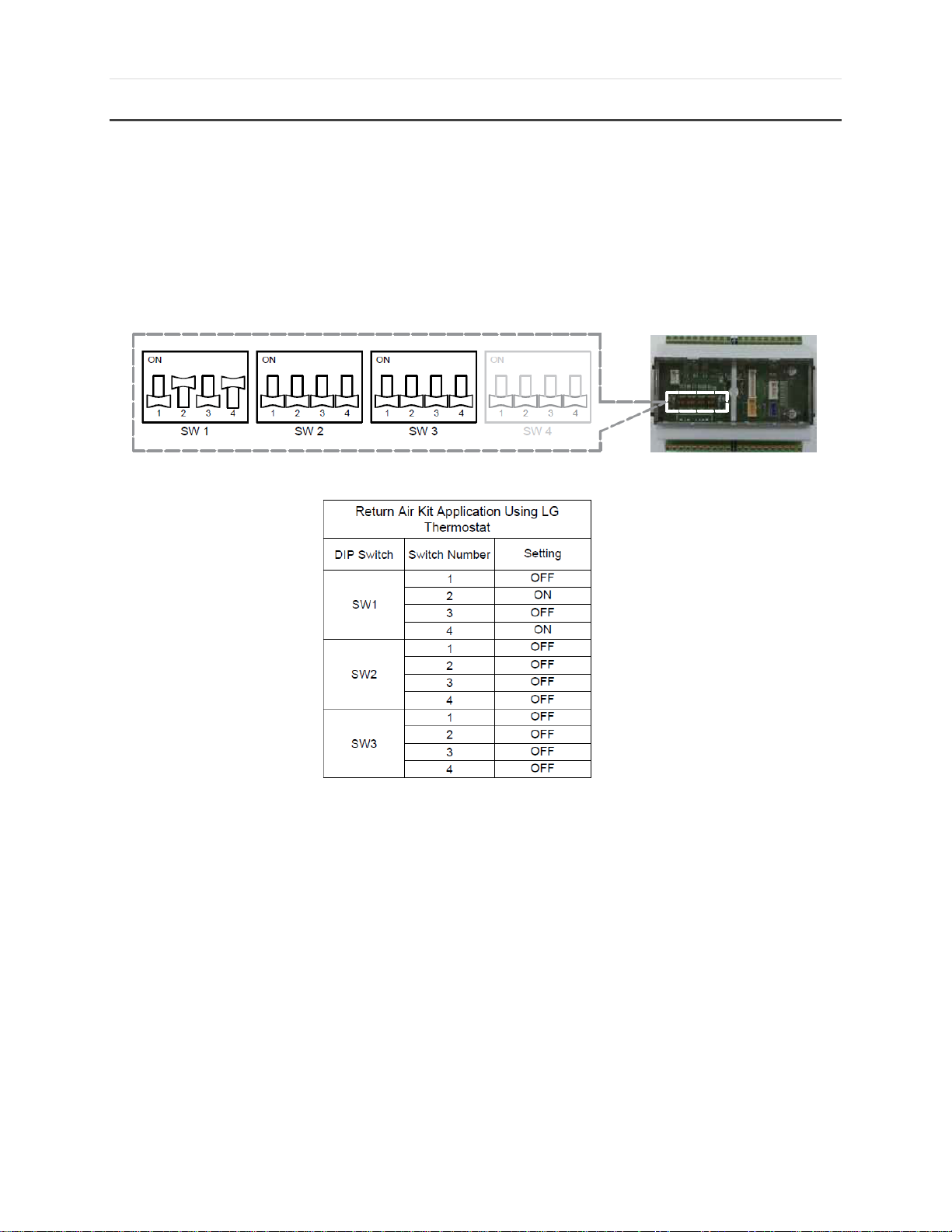
DIP Switch Applications with Thermostats – PAHCMR000
The figure below shows the DIP switch settings of the return air comm. kit when the LG controls is used.
When the LG controls method is used, an LG wired controller is required and LG central controller is
optional.
Figure 8. Return Air Kit DIP Switch Application Using LG Thermostat
VRF-WP-AH-001-US1018
Due to our policy of continuous product innovation, some specifications may change without notification
©LG Electronics U.S.A., Inc., Englewood Cliffs, NJ. All rights reserved. “LG” is a registered trademark of LG Corp.
Page 26
26 | P a g e
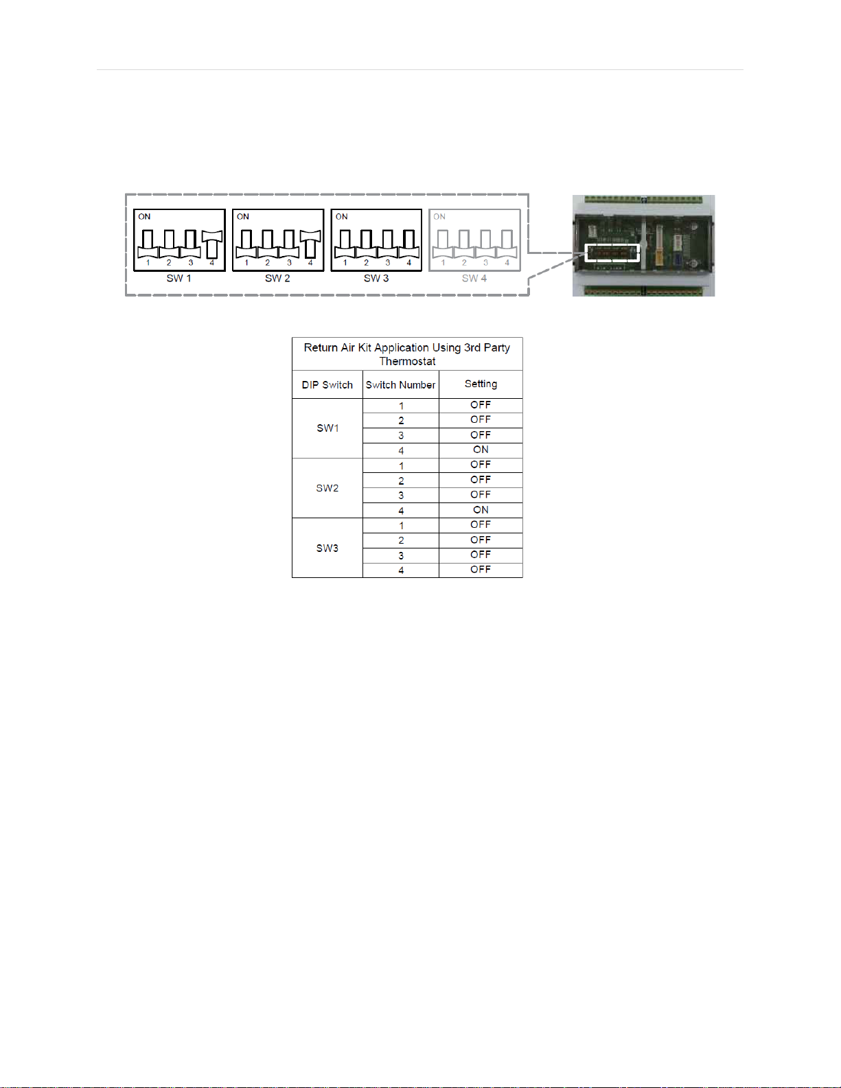
The figure below shows the DIP switch settings for the return air comm. kit when a 3rd party thermostat is
used. When a 3rd party thermostat is used, LG wired controller and LG central controllers are optional.
Figure 9. Return Air Kit DIP Switch Application Using 3rd Party Thermostat
VRF-WP-AH-001-US1018
Due to our policy of continuous product innovation, some specifications may change without notification
©LG Electronics U.S.A., Inc., Englewood Cliffs, NJ. All rights reserved. “LG” is a registered trademark of LG Corp.
Page 27

27 | P a g e
S/W name
No
Item
Setting
Note
SW1
1
Control Type
On
Communication
Controlled by DDC through Modbus or LG
centralized controller
Off
Contact Signal
Controlled by DDC through Contact signal AI and DI
LG Centralized controller can only monitor status
2
Discharge Temp.
Control Type
On
Stand alone
Discharge temp. control by LG controller using own
discharge temp. sensor
Off
Manual by DDC
Discharge temp. control by DDC using field supplied
discharge temp. sensor
3
Defrost
Operation Type
On
Normal
In case of multiple outdoor units, Defrost operation
can be operated simultaneously
Off
Sequential
Start up
In case of multiple outdoor units, the outdoor unit
is sequentially started at intervals of 10 minutes
4
Central
Communication
Type
On
LG Central Comm
Modbus Communication
Off
-
Not Used
SW2
1
ODU Capacity
Control
(1)
On
ODU Capacity Setting #2
ODU capacity control #2
Off
ODU Capacity Setting #1
ODU capacity control #1
2
Reserved - -
-
3
Reserved - -
-
4
Reserved
-
-
-
SW3
1
Reserved - -
-
2
Reserved
-
-
-
3
Reserved
-
-
-
4
Reserved - -
-
SW4
1
Reserved - -
-
2
Reserved - -
-
3
Reserved - -
-
4
Reserved - -
-
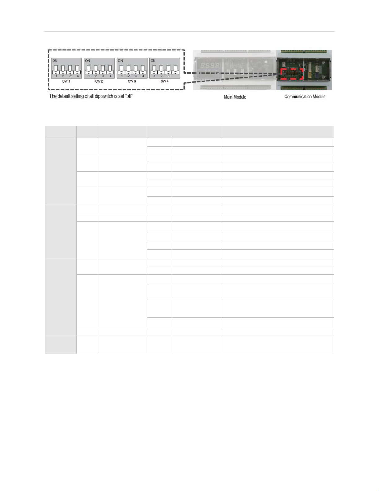
DIP Switch Settings – PAHCMS000
Figure 10. Main Module DIP Switches
Notes: (1) Refer to the Installation Manual for ODU Capacity Controls
VRF-WP-AH-001-US1018
Due to our policy of continuous product innovation, some specifications may change without notification
©LG Electronics U.S.A., Inc., Englewood Cliffs, NJ. All rights reserved. “LG” is a registered trademark of LG Corp.
Table 4. Main Module DIP Switch Settings
Page 28
28 | P a g e
S/W name
No
Item
Setting
Note
SW1
1
ODU Type
On
Single Comm
Using Single Split outdoor unit
Off
Multi V Comm
Using Multi V outdoor unit
2
Control Type
On
Communication
Controlled by Modbus between modules
Off
Contact signal
Not used
3
DO Type
On
Fan Speed
Not used
Off
Status
Not used
4
Fan Speed
(TH. On/Off)
On
Fixed
Not used
Off
Change
Not used
SW2
1
Reserved - -
-
2
Reserved - -
-
3/4
UI Setting
(1)
Off/Off
UI Setting #1
Not used
Off/On
UI Setting #2
Not used
On/Off
-
-
On/On
-
-
SW3
1
Master/Slave
On
Slave mode
Not used
Off
Master mode
Master is default
2/3
Operation mode
setting
Off/Off
Heat Pump
Cooling or Heating operation mode is available
Off/On
Heating Only
Operation mode is Heating only
(Heating/Ventilation)
On/Off
Cooling Only
Operation mode is Cooling only
(Cooling/Ventilation)
On/On
Reserved
4
Reserved - -
-
SW4
1-4
Capacity Index
Setting
-
-
According to ODU Type, you can setup the
capacity index of Multi V or Single Split
Figure 11. Communications Module DIP Switches
Notes: (1) Refer to the Installation Manual for UI settings
VRF-WP-AH-001-US1018
©LG Electronics U.S.A., Inc., Englewood Cliffs, NJ. All rights reserved. “LG” is a registered trademark of LG Corp.
Due to our policy of continuous product innovation, some specifications may change without notification
Table 5. Communications Module DIP Switch Settings
Page 29
29 | P a g e
Note: Outdoor unit central control address must be set to “01”
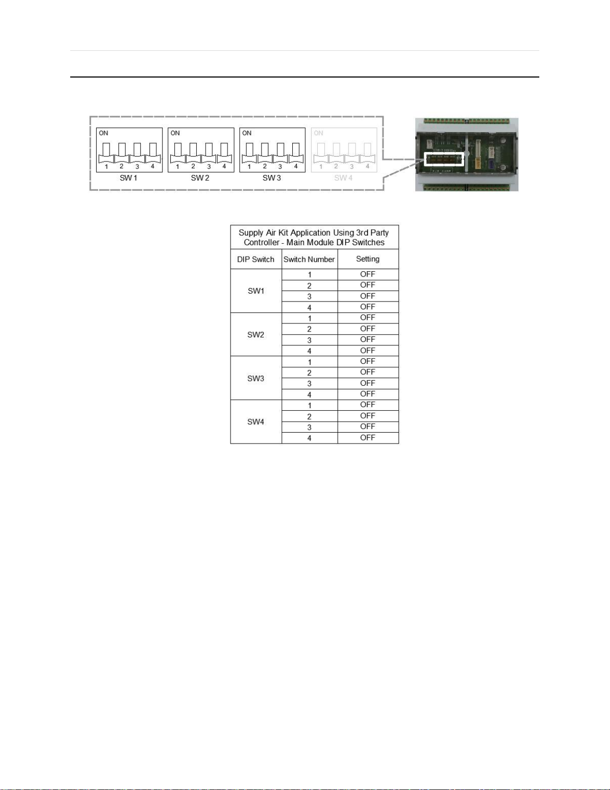
DIP Switch Application with Thermostats – PAHCMS000
Figure 12. Supply Air Kit Application Using 3rd Party Controller (Main Module)
VRF-WP-AH-001-US1018
Due to our policy of continuous product innovation, some specifications may change without notification
©LG Electronics U.S.A., Inc., Englewood Cliffs, NJ. All rights reserved. “LG” is a registered trademark of LG Corp.
Page 30

30 | P a g e
Note: Outdoor unit central control address must be set to “01”
Figure 13. Supply Air Kit Application Using 3
VRF-WP-AH-001-US1018
Due to our policy of continuous product innovation, some specifications may change without notification
©LG Electronics U.S.A., Inc., Englewood Cliffs, NJ. All rights reserved. “LG” is a registered trademark of LG Corp.
rd
Party Controller (Comm. Module)
Page 31

31 | P a g e
Model
Single Split
Capacity Index
kBtu/h
9
12
18
24
36
42
Communication Kit
PAHCMR000
O O O O O O PAHCMS000
X X O O X
X
Model
Multi V
Multi V Water
5
IV
III S IV
II
Mini
Communication
Kit
PAHCMR000
O O O O O O O
PAHCMS000
O O O O O O X
Comm Kit Combinations
Combination Options
Table 6. Compatibility with Outdoor Units
Table 6 shows the compatibilities of the communication kits with different outdoor units. The return air
communication kit (PAHCMR000) is compatible with Multi V 5, IV, III, S, Multi V Water IV, II and Mini. The
supply air communication kit (PAHCMS000) is compatible with Multi V 5, IV, III, S, Multi V Water IV and II.
The supply air communication kit is not compatible with Multi V Water Mini. The table also presents the
compatibilities of the communication kits with Single Split models of different capacities.
Figure 14. Communication Kit Combination
VRF-WP-AH-001-US1018
Due to our policy of continuous product innovation, some specifications may change without notification
©LG Electronics U.S.A., Inc., Englewood Cliffs, NJ. All rights reserved. “LG” is a registered trademark of LG Corp.
Page 32

32 | P a g e
1:1 Combination
EEV Kit Combinations
1:2 Combination
VRF-WP-AH-001-US1018
Due to our policy of continuous product innovation, some specifications may change without notification
©LG Electronics U.S.A., Inc., Englewood Cliffs, NJ. All rights reserved. “LG” is a registered trademark of LG Corp.
Page 33

33 | P a g e
PRLK048/096A0 + PRLK396/594A0 Combination – Not Possible
PRLK048/096A0 + PRLK396/594A0 combination is not allowed
o PRLK048A0 + PRLK396A0
o PALK048A0 + PRLK594A0
o PRLK096A0 + PALK396A0
o PRLK096A0 + PRLK594A0
VRF-WP-AH-001-US1018
Due to our policy of continuous product innovation, some specifications may change without notification
©LG Electronics U.S.A., Inc., Englewood Cliffs, NJ. All rights reserved. “LG” is a registered trademark of LG Corp.
Page 34

34 | P a g e
PRLK594A0 + PRLK594A0 Combination – Not Possible
PRLK594A0 + PRLK594A0 combination is not allowed
PRLK396A0 + PRLK594A0 Combination – Not Possible
PRLK396A0 + PRLK594A0 combination is not allowed
VRF-WP-AH-001-US1018
Due to our policy of continuous product innovation, some specifications may change without notification
©LG Electronics U.S.A., Inc., Englewood Cliffs, NJ. All rights reserved. “LG” is a registered trademark of LG Corp.
Page 35

35 | P a g e
Combination
Total
AHU
Indoor units
Expansion kit type
Pair
(1 ODU to 1 AHU)
90 - 105%
-105% - EEV kit
Multiple
(1 ODU to multiple AHUs)
90 - 110%
-110% - EEV kit
Multiple (1
ODU to multiple AHUs +
indoor units)
50 - 110%
-50%
50 - 110%
EEV kit
50 - 130%
-30%
50 – 130%
EEV kit
EEV + IDU Combination – Not Possible
PRLK396/594A0 + Indoor Unit combination is not allowed
EEV Kit Combination Ratio
• Heat pump system
Note: 1. Combination ratio (%) = Sum of total capacity index / Outdoor unit rated cooling capacity
2. A DX coil capacity should be less than or equal to 100% of the outdoor unit capacity
Table 7. EEV Kit Combination Ratio for Heat Pump System
VRF-WP-AH-001-US1018
Due to our policy of continuous product innovation, some specifications may change without notification
©LG Electronics U.S.A., Inc., Englewood Cliffs, NJ. All rights reserved. “LG” is a registered trademark of LG Corp.
Page 36

36 | P a g e
Application Cases for Communication Kits
Return Air Control – 1-ODU System + 1 AHU (1 coil) + Controls
*
LG thermostats with AHU conversion kit can only do single setpoint
LG thermostats with AHU conversion kit cannot do auto switchover mode
1. 1-ODU System + 1 AHU (1 coil) + LG Control
1 ODU can be connected with multiple EEV kits
EEV kit should be connected with communication kit 1:1
2. 1-ODU System + 1 AHU (1 coil) + DDC (Modbus)
1 ODU can be connected with multiple EEV kits
EEV kit should be connected with communication kit 1:1
LG Remote Controller and LG Central Controller are optional
VRF-WP-AH-001-US1018
Due to our policy of continuous product innovation, some specifications may change without notification
©LG Electronics U.S.A., Inc., Englewood Cliffs, NJ. All rights reserved. “LG” is a registered trademark of LG Corp.
Page 37

37 | P a g e
Return Air Control – 1-ODU System + 1 AHU (2 coil) + Controls
*
LG thermostats with AHU conversion kit can only do single setpoint
LG thermostats with AHU conversion kit cannot do auto switchover mode
1. 1-ODU System + 1 AHU (2 coils) + LG Control
1 ODU can be connected with multiple EEV kits
1 Communication kit & 1 EEV kit are necessary for each coil
Group control of coils is needed normally
2. 1-ODU System + 1 AHU (2 coils) + DDC (Modbus)
1 ODU can be connected with multiple EEV kits
1 communication kit & 1 EEV kit are necessary for each coil
Group control of coils is need normally
VRF-WP-AH-001-US1018
Due to our policy of continuous product innovation, some specifications may change without notification
©LG Electronics U.S.A., Inc., Englewood Cliffs, NJ. All rights reserved. “LG” is a registered trademark of LG Corp.
Page 38

38 | P a g e
Return Air Control – 1-ODU System + 1 AHU (1 coil) + IDU + Controls
*LG thermostats with AHU conversion kit can only do single setpoint
LG thermostats with AHU conversion kit cannot do auto switchover mode
1. 1-ODU System + 1 AHU (1 coil) + Indoor Units + LG Control
1 ODU can be connected with multiple EEV kits
EEV kit can be used with other indoor units
1 communication kit & 1 EEV kit are necessary for each coil
2. 1-ODU System + 1 AHU (1 coil) + Indoor Units + DDC (Modbus)
VRF-WP-AH-001-US1018
Due to our policy of continuous product innovation, some specifications may change without notification
©LG Electronics U.S.A., Inc., Englewood Cliffs, NJ. All rights reserved. “LG” is a registered trademark of LG Corp.
Page 39
39 | P a g e
1 ODU can be connected with multiple EEV kits
EEV kit can be used with other indoor units
1 communication kit & 1 EEV kit are necessary for each coil
Return Air Control – 1-ODU System + 1 AHU (2 coil) + IDU + Controls
*
LG thermostats with AHU conversion kit can only do single setpoint
LG thermostats with AHU conversion kit cannot do auto switchover mode
1. 1-ODU System + 1 AHU (2 coils) + Indoor Units + LG Control
1 ODU can be connected with multiple EEV kits
EEV kit can be used with other indoor units
1 communication kit & 1 EEV kit are necessary for each coil
VRF-WP-AH-001-US1018
Due to our policy of continuous product innovation, some specifications may change without notification
©LG Electronics U.S.A., Inc., Englewood Cliffs, NJ. All rights reserved. “LG” is a registered trademark of LG Corp.
Page 40

40 | P a g e
2. 1-ODU System + 1 AHU (2 coils) + Indoor Units + DDC (Modbus)
1 ODU can be connected with multiple EEV kits
EEV kit can be used with other indoor units
1 communication kit & 1 EEV kit are necessary for each coil
Return Air Control – 1-ODU System + Multiple AHU’s + Controls
*
LG thermostats with AHU conversion kit can only do single setpoint
LG thermostats with AHU conversion kit cannot do auto switchover mode
1. 1-ODU System + Multiple AHU’s + LG Control
VRF-WP-AH-001-US1018
Due to our policy of continuous product innovation, some specifications may change without notification
©LG Electronics U.S.A., Inc., Englewood Cliffs, NJ. All rights reserved. “LG” is a registered trademark of LG Corp.
Page 41

41 | P a g e
1 ODU can be connected with multiple EEV kits
EEV kits can be used with other indoor units
1 communication kit & 1 EEV kit are necessary for each coil
2. 1-ODU System + Multiple AHU’s + DDC (Contact)
1 ODU can be connected with multiple EEV kits
EEV kits can be used with other indoor units
1 communication kit & 1 EEV kit are necessary for each coil
LG Remote Controller and LG Central Controller can be used for monitoring only
3. 1-ODU System + Multiple AHU’s + DDC (Modbus)
1 ODU can be connected with multiple EEV kits
VRF-WP-AH-001-US1018
Due to our policy of continuous product innovation, some specifications may change without notification
©LG Electronics U.S.A., Inc., Englewood Cliffs, NJ. All rights reserved. “LG” is a registered trademark of LG Corp.
Page 42
42 | P a g e
EEV kits can be used with other indoor units
1 communication kit & 1 EEV kit are necessary for each coil
Return Air Control – 2-ODU System + 1 AHU (2 coils) + Controls
*LG thermostats with AHU conversion kit can only do single setpoint
LG thermostats with AHU conversion kit cannot do auto switchover mode
1. 2-ODU System + 1 AHU (2 coils) + LG Control
1 ODU can be connected with multiple EEV kits
1 communication kit & 1 EEV kit are necessary for each coil
2. 2-ODU System + 1 AHU (2 coils) + DDC (Modbus)
1 ODU can be connected with multiple EEV kits
VRF-WP-AH-001-US1018
Due to our policy of continuous product innovation, some specifications may change without notification
©LG Electronics U.S.A., Inc., Englewood Cliffs, NJ. All rights reserved. “LG” is a registered trademark of LG Corp.
Page 43

43 | P a g e
1 communication kit & 1 EEV kit are necessary for each coil
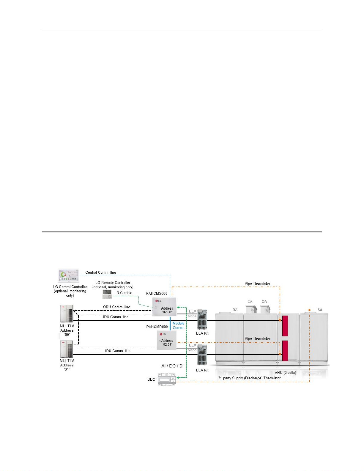
Supply Air Control – 1-ODU System + 1 AHU (1 coils) + Controls
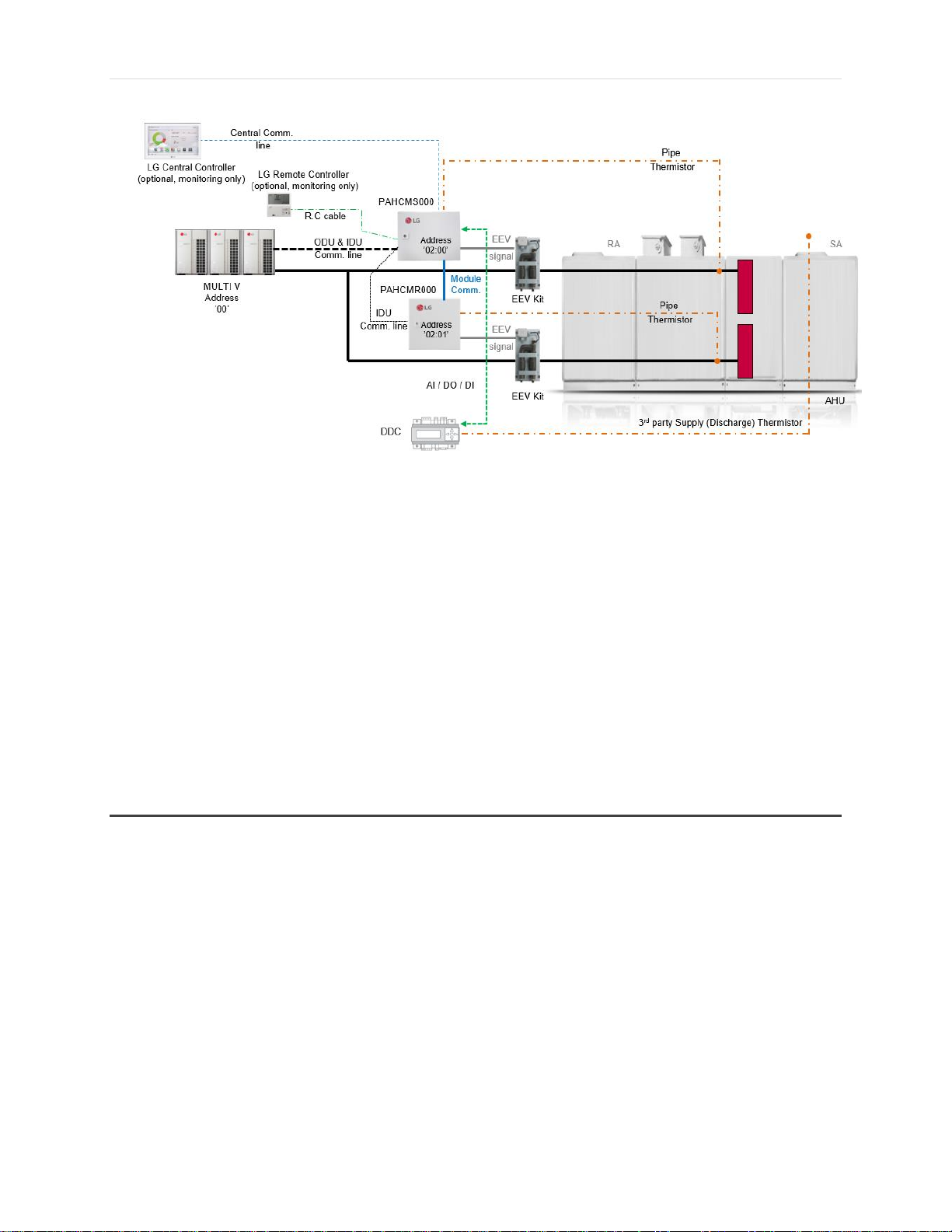
1. 1-ODU System + 1 AHU (1 coil) + DDC (Contact)
DDC controls ODU capacity through the communication kit to meet required
discharge air temperature
rd
3
party discharge thermistor is required to feedback ODU capacity to the
communication kit
LG Central Controller is connected directly to the communication kit, not to ODU
Multi V ODU and communication kit (right side module) address should match for
capacity control and can only be set as “00”, “01”, “02”, “03”
LG Remote Controller and LG Central Controller can be used for monitoring only
LG Central Control address must match Communication Kit (left side module) address
which can be set using communication kit Tact buttons
2. 1-ODU System + 1 AHU (1 coil) + DDC (Modbus)
VRF-WP-AH-001-US1018
Due to our policy of continuous product innovation, some specifications may change without notification
©LG Electronics U.S.A., Inc., Englewood Cliffs, NJ. All rights reserved. “LG” is a registered trademark of LG Corp.
Page 44

44 | P a g e
With Modbus control, discharge air can be controlled in 2 methods
1) ODU Capacity Control (3rd party discharge thermistor is required)
a) DDC controls ODU capacity through communication kit to meet
required discharge air temperature
b) 3rd party discharge thermistor is required to feedback ODU capacity to
communication kit
LG Central Controller is connected directly to the communication kit, not to ODU
Multi V and communication kit address should be kept as “00” (default “00”)
Multi V ODU and communication kit (right side module) address should match for
capacity control and can only be set as “00”, “01”, “02”, “03”
LG Central Control address must match Communication Kit (left side module) address
which can be set using communication kit Tact buttons
Supply Air Control – 1-ODU System + 1 AHU (2 coils) + Controls
1. 1-ODU System + 1 AHU (2 coils) + DDC (Contact)
VRF-WP-AH-001-US1018
Due to our policy of continuous product innovation, some specifications may change without notification
©LG Electronics U.S.A., Inc., Englewood Cliffs, NJ. All rights reserved. “LG” is a registered trademark of LG Corp.
Page 45
45 | P a g e
LG Central Controller is connected directly to communication kit (PAHCMS000), not to
ODU
EEV kits should be connected with communication kits 1:1
Additional PAHCMR000 can be connected to expand the number of DX coil. Maximum
of 3 return air communication kits can be used for 1 supply air communication kit –
maximum applicable DX coil for 1 ODU system is 4
LG Remote Controller and LG Central Controller can be used for monitoring only
Multi V ODU and communication kit (right side module) address should match for
capacity control and can only be set as “00”, “01”, “02”, “03”
LG Central Control address must match Communication Kit (left side module) address
which can be set using communication kit Tact buttons
Supply Air Control – 1-ODU System + Multiple AHU’s
VRF-WP-AH-001-US1018
Due to our policy of continuous product innovation, some specifications may change without notification
©LG Electronics U.S.A., Inc., Englewood Cliffs, NJ. All rights reserved. “LG” is a registered trademark of LG Corp.
Page 46

46 | P a g e
For supply air control, single connection without another IDU or AHU is recommended
: Supply air temperature control kit adjusts pressure (or AHU coil
temperature) so 2 AHU’s have the same coil temperature
It is not possible to have different coil temperatures
Supply Air Control – 1-ODU System + 1 AHU (1 coil) + IDU’s
For supply air control, single connection without another IDU or AHU is recommended
VRF-WP-AH-001-US1018
Due to our policy of continuous product innovation, some specifications may change without notification
©LG Electronics U.S.A., Inc., Englewood Cliffs, NJ. All rights reserved. “LG” is a registered trademark of LG Corp.
Page 47

47 | P a g e
: Supply air temperature control kit adjusts pressure (or AHU coil
temperature)
IDU capacity could be changed when supply air control kit controls AHU
Supply Air Control – 1-ODU System + 1 AHU (2 coils) + IDU’s
For supply air control, single connection without another IDU or AHU is recommended
VRF-WP-AH-001-US1018
Due to our policy of continuous product innovation, some specifications may change without notification
©LG Electronics U.S.A., Inc., Englewood Cliffs, NJ. All rights reserved. “LG” is a registered trademark of LG Corp.
Page 48
48 | P a g e
: Supply air temperature control kit adjusts pressure (or AHU coil
temperature)
IDU capacity could be changed when supply air control kit controls AHU
Supply Air Control – 2-ODU System + 1 AHU (2 coils)
1. 2-ODU System + 1 AHU (2 coils) + DDC (Contact)
LG Central Controller is connected directly to the communication kit (PAHCMS000),
not to ODU
EEV kits should be connected with communication kits 1:1
VRF-WP-AH-001-US1018
Due to our policy of continuous product innovation, some specifications may change without notification
©LG Electronics U.S.A., Inc., Englewood Cliffs, NJ. All rights reserved. “LG” is a registered trademark of LG Corp.
Page 49

49 | P a g e
Additional PAHCMR000 can be connected to expand the number of DX coil. Maximum
of 3 return air communication kits can be used for 1 supply air communication kit –
maximum applicable DX coil for 1 ODU system is 4
LG remote controller and LG central controller can be used for monitoring only
Multi V ODU and communication kit (right side module) address should match for
capacity control and can only be set as “00”, “01”, “02”, “03”
LG Central Control address must match Communication Kit (left side module) address
which can be set using communication kit Tact buttons
Supply Air Control – 1-ODU System + 1 AHU (2 coils) + I/O Module + DDC
Control
I/O Modules (PRVC2 and PWFCKN000) have capacity control feature built-in
VRF-WP-AH-001-US1018
Due to our policy of continuous product innovation, some specifications may change without notification
©LG Electronics U.S.A., Inc., Englewood Cliffs, NJ. All rights reserved. “LG” is a registered trademark of LG Corp.
Page 50

50 | P a g e
LG Central controller can be connected to ODU
VRF-WP-AH-001-US1018
Due to our policy of continuous product innovation, some specifications may change without notification
©LG Electronics U.S.A., Inc., Englewood Cliffs, NJ. All rights reserved. “LG” is a registered trademark of LG Corp.
Page 51

51 | P a g e
Example AHU Kit for Large AHU
Components Required
LG Wired Controller
PAHCMS000 Communication Kit (Supply Air)
EEV Kit
Multi V ODU
3rd Party AHU
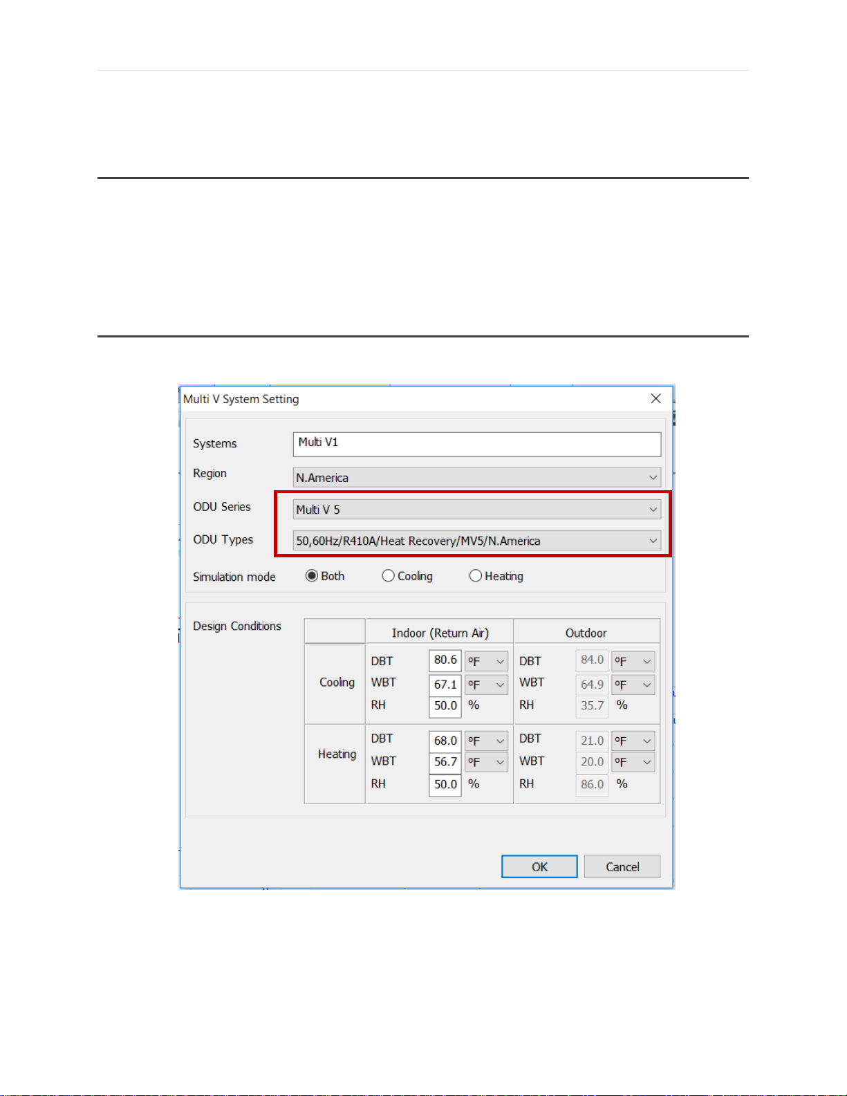
Selecting in LATS HVAC
When creating your LATS HVAC project, make sure to choose a Multi V Outdoor Unit. Note that
PAHCMS000 Units are only compatible with Heat Pump systems.
VRF-WP-AH-001-US1018
Due to our policy of continuous product innovation, some specifications may change without notification
©LG Electronics U.S.A., Inc., Englewood Cliffs, NJ. All rights reserved. “LG” is a registered trademark of LG Corp.
Page 52

52 | P a g e
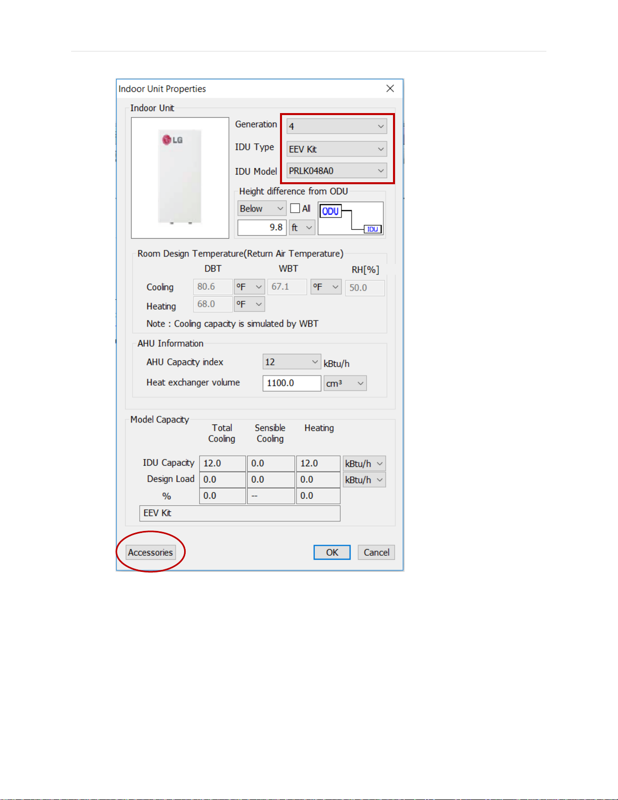
When selecting an indoor
Unit, choose “EEV Kit” under
IDU Type.
PRLK048A0, PRLK096A0,
PRLK396A0 and PRLK594A0
are available EEV kit choices
After selecting the EEV Kit, click on
“Accessories” to add the Comm. Kit
and thermostat
VRF-WP-AH-001-US1018
Due to our policy of continuous product innovation, some specifications may change without notification
©LG Electronics U.S.A., Inc., Englewood Cliffs, NJ. All rights reserved. “LG” is a registered trademark of LG Corp.
Page 53

53 | P a g e
Choose the PAHCMS000 as the
communication kit and one of the
LG wired controllers, then click
“Add” and “Ok”. Note that the
thermostat is used for displaying
error codes only when DDC by
contact signal is used
VRF-WP-AH-001-US1018
Due to our policy of continuous product innovation, some specifications may change without notification
©LG Electronics U.S.A., Inc., Englewood Cliffs, NJ. All rights reserved. “LG” is a registered trademark of LG Corp.
Page 54

54 | P a g e
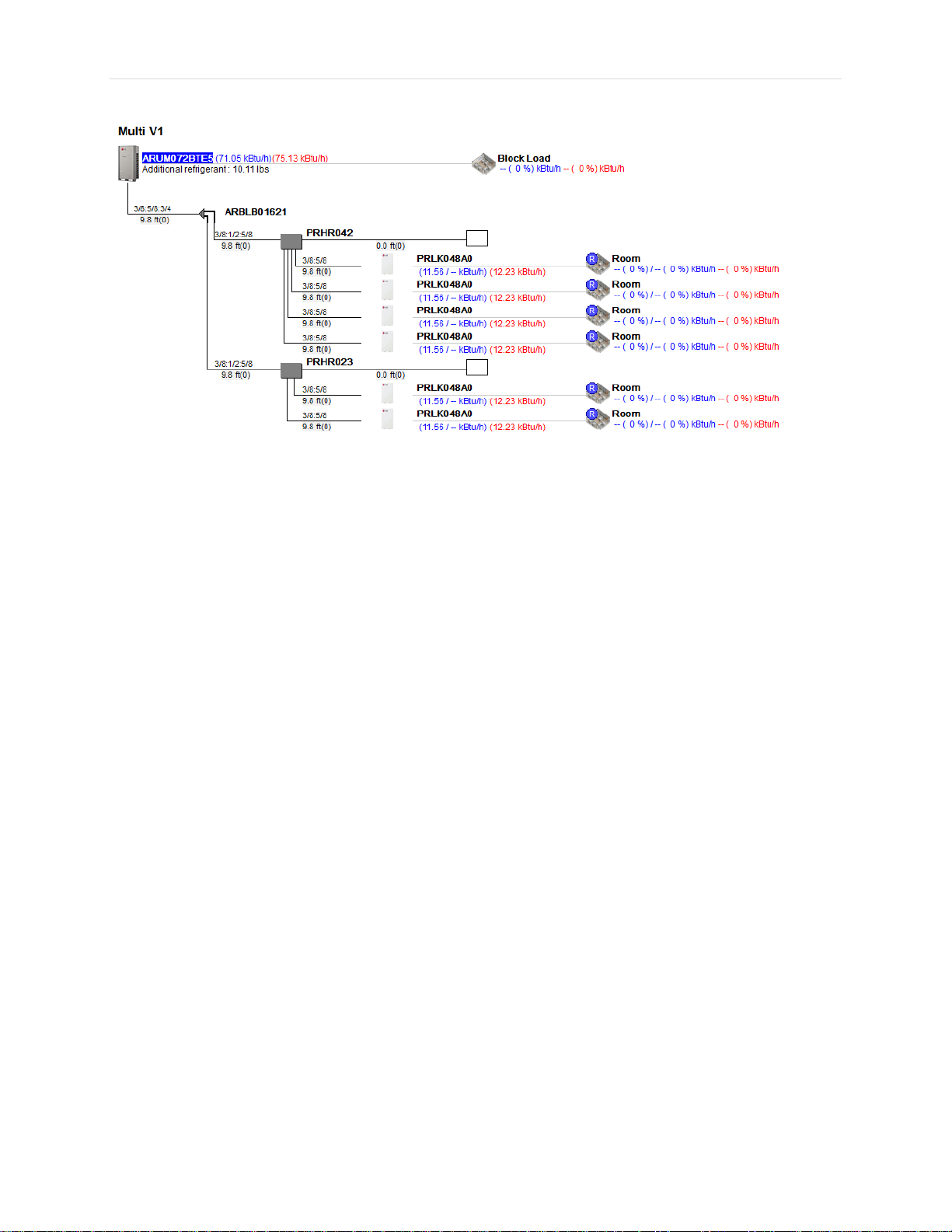
Here’s an example of a Large AHU system in LATS HVAC. The combination ratios in Table 6 should be
followed when designing with the AHU kits.
VRF-WP-AH-001-US1018
Due to our policy of continuous product innovation, some specifications may change without notification
©LG Electronics U.S.A., Inc., Englewood Cliffs, NJ. All rights reserved. “LG” is a registered trademark of LG Corp.
Page 55
55 | P a g e
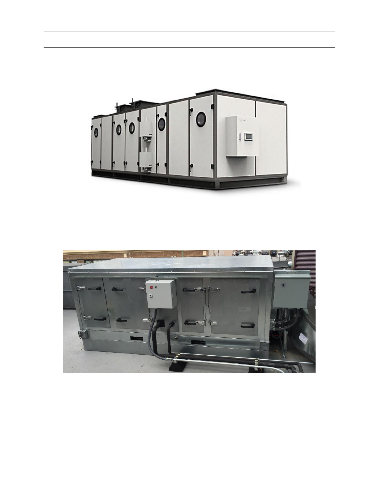
Application Types
Figure 15. VAV/Central Station Air Handler
Figure 16. Rooftop Air Handler
VRF-WP-AH-001-US1018
Due to our policy of continuous product innovation, some specifications may change without notification
©LG Electronics U.S.A., Inc., Englewood Cliffs, NJ. All rights reserved. “LG” is a registered trademark of LG Corp.
Page 56

56 | P a g e
Figure 17. Custom Air Handler
VRF-WP-AH-001-US1018
Due to our policy of continuous product innovation, some specifications may change without notification
©LG Electronics U.S.A., Inc., Englewood Cliffs, NJ. All rights reserved. “LG” is a registered trademark of LG Corp.
Page 57
57 | P a g e
Outdoor Unit
Indoor Units
Controller
MV-V Water IV HP
(64 Tons)
33,000 CFM AHU x 1
3rd Party BMS
• PAHCMS000 Comm. Kit for outside air pre‐conditioning to meet
specific discharge air temperature.
• MV‐Water IV units mounted, piped, and wired at AHU
manufacturer.
Application Examples
Office Building
VRF-WP-AH-001-US1018
Due to our policy of continuous product innovation, some specifications may change without notification
©LG Electronics U.S.A., Inc., Englewood Cliffs, NJ. All rights reserved. “LG” is a registered trademark of LG Corp.
Page 58
58 | P a g e
AHU Conversion Kit for Small AHU
Components Required
PAHCMR000 Communication Kit (Return Air)
EEV Kit
Multi V ODU
LG wired controller
3rd Party AHU
Selecting in LATS HVAC
When creating your LATS-HVAC project, make sure to choose a Multi V Outdoor Unit. Note that both
PAHCMR000 and PAHCMS000 units are compatible with both Heat Recovery and Heat Pump systems.
VRF-WP-AH-001-US1018
Due to our policy of continuous product innovation, some specifications may change without notification
©LG Electronics U.S.A., Inc., Englewood Cliffs, NJ. All rights reserved. “LG” is a registered trademark of LG Corp.
Page 59
59 | P a g e
After selecting the EEV Kit, click on
“Accessories” to add the Comm. Kit
and thermostat
When selecting an indoor
Unit, choose “EEV Kit” under
IDU Type.
For Heat Recovery systems,
only PRLK48A0 can be used.
VRF-WP-AH-001-US1018
Due to our policy of continuous product innovation, some specifications may change without notification
©LG Electronics U.S.A., Inc., Englewood Cliffs, NJ. All rights reserved. “LG” is a registered trademark of LG Corp.
Page 60

60 | P a g e
Choose the PAHCMR000 as the
communication kit and one of the LG
wired controllers, then click “Add” and
“Ok”.
VRF-WP-AH-001-US1018
Due to our policy of continuous product innovation, some specifications may change without notification
©LG Electronics U.S.A., Inc., Englewood Cliffs, NJ. All rights reserved. “LG” is a registered trademark of LG Corp.
Page 61
61 | P a g e
Here’s an example of a Small AHU system in LATS-HVAC. The combination ratio should follow the
rules in the combination ratio table (Table 6).
VRF-WP-AH-001-US1018
Due to our policy of continuous product innovation, some specifications may change without notification
©LG Electronics U.S.A., Inc., Englewood Cliffs, NJ. All rights reserved. “LG” is a registered trademark of LG Corp.
Page 62

62 | P a g e
Application Types
Figure 18. High Filtration
VRF-WP-AH-001-US1018
Due to our policy of continuous product innovation, some specifications may change without notification
©LG Electronics U.S.A., Inc., Englewood Cliffs, NJ. All rights reserved. “LG” is a registered trademark of LG Corp.
Figure 19. Large Gym Area
Page 63
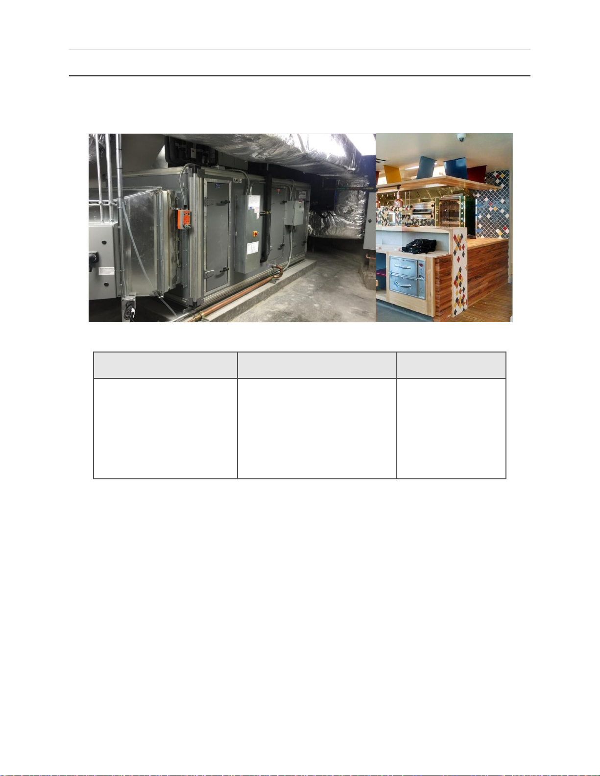
63 | P a g e
Outdoor Unit
Indoor Units
Controller
MV 5 HR
(28 Tons)
3700 CFM AHU x 1
Ducted x 9
High Wall x 3
AC Smart IV
• PAHCMR000 Comm. Kit for outside air pre‐conditioning.
• Standard LG IDU used for space conditioning.
• AC Smart Central Controller schedules LG systems. 3
rd
Party BMS controls
AHU fan speed.
Application Examples
Restaurant
VRF-WP-AH-001-US1018
Due to our policy of continuous product innovation, some specifications may change without notification
©LG Electronics U.S.A., Inc., Englewood Cliffs, NJ. All rights reserved. “LG” is a registered trademark of LG Corp.
Page 64
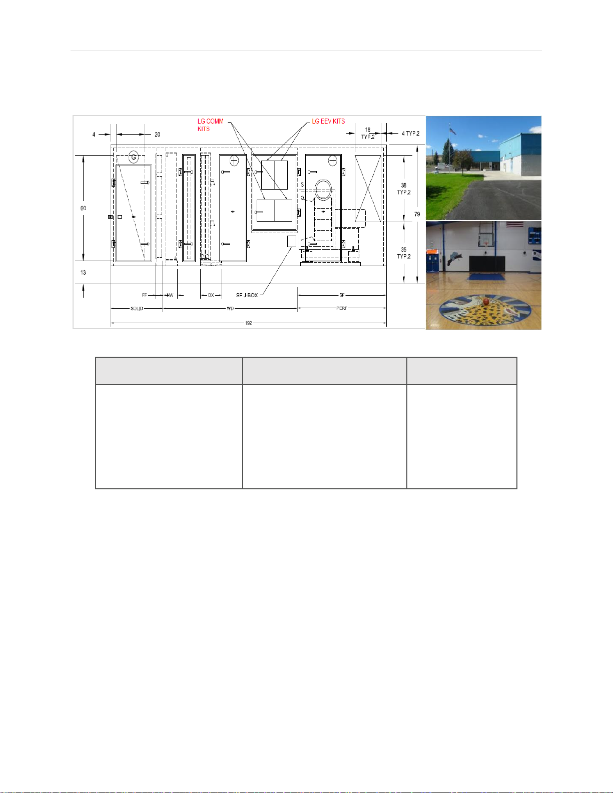
64 | P a g e
Outdoor Unit
Indoor Units
Controller
MV Water IV HR
MV Water IV HP
MV 5 Air HR
(128 Tons)
Ducted x 21
High-Wall x 1
12,000 CFM AHU x 1
BMS &
3rd Party Thermostat
• VRF equipment replacing WSHP to reduce site maintenance costs
and reduce classroom noise.
• PAHCMR000 Comm. Kit applied to Gym/Multipurpose Space AHU.
• LG AHU Kits installed and piped at AHU factory.
Elementary/High School
VRF-WP-AH-001-US1018
Due to our policy of continuous product innovation, some specifications may change without notification
©LG Electronics U.S.A., Inc., Englewood Cliffs, NJ. All rights reserved. “LG” is a registered trademark of LG Corp.
Page 65

65 | P a g e
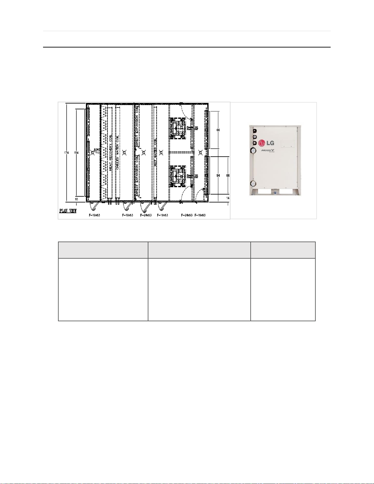
Coil Design Parameters
AHU Module – Design Tips (Do’s)
Minimum coil entering temperature is 41°F for heating mode.
AHU coil sizing parameters
• Cooling Mode
◦ Suction (evap) temperature for coil sizing is 41 - 43°F
◦ Condensing (liquid) temperature for coil sizing is 110°F
• Heating Mode
◦ Hot gas temperature at AHU coil is 113°F (range is 104 - 122°F)
◦ Recommended coil tube sizes are 3/8” or 1/2"
◦ Refrigerant pressure drop is 7.25 psi to 14.5 psi
◦ Coil volume data is needed from coil manufacturer to calculate refrigerant trim
charge amount
◦ Coils larger than 42 tons should be divided into multiple circuits to allow
connection of EEV kit
◦ Heat recovery systems are limited to 8 ton maximum coil size (can only tie 2
HRU ports together)
Pipe sizing rules are same rules as the connected ODU (see ODU Engineering Manual or
updated LATS version)
Maximum recommended combination ratio is 100%
Comm Kits and EEV Kits are not weather proof and must be protected from rai, snow,
etc.
VRF-WP-AH-001-US1018
Due to our policy of continuous product innovation, some specifications may change without notification
©LG Electronics U.S.A., Inc., Englewood Cliffs, NJ. All rights reserved. “LG” is a registered trademark of LG Corp.
Page 66
66 | P a g e
AHU Module – Design Tips (Dont’s)
Do not design AHU coil
• Rows, fins per inch, coil area, coil velocity are determined by coil manufacturer or
specifying engineer
Do not directly connect AHU fan motor (load) to AHU Comm Kit
• Fan motor control center (relays or starter) is required
Do not exceed outdoor design temperature limits for outdoor units
• 14°F minimum outdoor temperature for simultaneous operation of Multi V 5
• 60°F maximum on heating mode
Avoid using (1) cooling coil and (1) heating coil for reheat in same AHU (control setup is
very complicated)
Do not exceed air velocity of 550 FPM (feet per minute) to avoid blow off of condensate
water into airstream
AHU Module DX Coil Sizing Parameters – Cooling
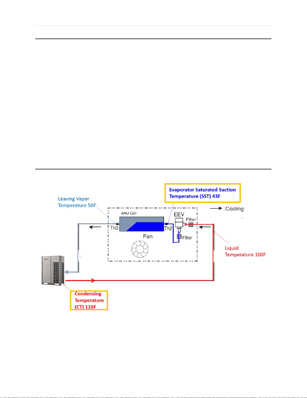
Superheat (Cooling Mode) = Th3 (pipe out temperature) – Th2 (pipe in temperature) = 7F
VRF-WP-AH-001-US1018
Due to our policy of continuous product innovation, some specifications may change without notification
©LG Electronics U.S.A., Inc., Englewood Cliffs, NJ. All rights reserved. “LG” is a registered trademark of LG Corp.
Page 67

67 | P a g e
AHU Module DX Coil Sizing Parameters – Heating
Subcooling (Heating mode) = SCT – Leaving Liquid Temperature (Th2) = 9F
VRF-WP-AH-001-US1018
Due to our policy of continuous product innovation, some specifications may change without notification
©LG Electronics U.S.A., Inc., Englewood Cliffs, NJ. All rights reserved. “LG” is a registered trademark of LG Corp.
Page 68

68 | P a g e
Circuit Diagram
Supply Air Communication Kit - PAHCMS000
VRF-WP-AH-001-US1018
Due to our policy of continuous product innovation, some specifications may change without notification
©LG Electronics U.S.A., Inc., Englewood Cliffs, NJ. All rights reserved. “LG” is a registered trademark of LG Corp.
Page 69

69 | P a g e
Return Air Communication Kit - PAHCMR000
VRF-WP-AH-001-US1018
Due to our policy of continuous product innovation, some specifications may change without notification
©LG Electronics U.S.A., Inc., Englewood Cliffs, NJ. All rights reserved. “LG” is a registered trademark of LG Corp.
 Loading...