

LG ACHH060LBAB Owner’s Manual

INSTALLATION &
OWNER’S MANUAL
www.lg.com
Please read this installation manual completely before installing the product.
Installation work must be performed in accordance with the national wiring standards by authorized
personnel only.
Please retain this installation manual for future reference after reading it thoroughly.
Please read this manual carefully before operating your set and retain it
for future reference.
[Representative] LG Electronics Inc. EU Representative : LG Electronics European Shared Service
Center B.V. Krijgsman 1, 1186 DM Amstelveen, The Netherlands
[Manufacturer] LG Electronics Inc. Changwon 2nd factory 84, Wanam-ro, Seongsan-gu,
Changwon-si, Gyeongsangnam-do, KOREA
Air Cooled Liquid Chilling Package
ACHH Series
Original instruction
AIR
CONDITIONER
MFL67262615
Rev.01_120320
Copyright © 2018 - 2020 LG Electronics Inc. All Rights Reserved.
SVENSKA
ENGLISH
ITALIANO
NORSK
ESPAÑOL
DANSK
FRANÇAIS
DEUTSCH
ΕΛΛΗΝΙΚΆ
ČEŠTINA
NEDERLANDS
POLSKI
LIMBA ROMÂNĂ
TIPS FOR SAVING ENERGY
2
ENGLISH
TIPS FOR SAVING ENERGY
Here are some tips that will help you minimize the power consumption when you use the air
conditioner. You can use your air conditioner more efficiently by referring to the instructions
below:
• Do not cool excessively indoors. This may be harmful for your health and may consume more
electricity.
• Block sunlight with blinds or curtains while you are operating the air conditioner.
• Keep doors or windows closed tightly while you are operating the air conditioner.
• Adjust the direction of the air flow vertically or horizontally to circulate indoor air.
• Speed up the fan to cool or warm indoor air quickly, in a short period of time.
• Open windows regularly for ventilation as the indoor air quality may deteriorate if the air conditioner is used for many hours.
• Clean the air filter once every 2 weeks. Dust and impurities collected in the air filter may block the
air flow or weaken the cooling / dehumidifying functions.
ENGLISH Disposal of your old appliance
1. This crossed-out wheeled bin symbol indicates that waste electrical and electronic products
(WEEE) should be disposed of separately from the municipal waste stream.
2. Old electrical products can contain hazardous substances so correct disposal of your old appli-
ance will help prevent potential negative consequences for the environment and human health.
Your old appliance may contain reusable parts that could be used to repair other products, and
other valuable materials that can be recycled to conserve limited resources.
3. You can take your appliance either to the shop where you purchased the product, or contact your
local government waste office for details of your nearest authorised WEEE collection point. For
the most up to date information for your country please see www.lg.com/global/recycling
For your records
Staple your receipt to this page in case you need it to prove the date of purchase or for warranty
purposes. Write the model number and the serial number here:
Model number :
Serial number :
You can find them on a label on the side of each unit.
Dealer’s name :
Date of purchase :

IMPORTANT SAFETY INSTRUCTIONS
3
IMPORTANT SAFETY INSTRUCTIONS
READ ALL INSTRUCTIONS BEFORE USING THE APPLIANCE.
Always comply with the following precautions to avoid dangerous
situations and ensure peak performance of your product.
WARNING
!
It can result in serious injury or death when the directions are
ignored.
CAUTION
!
It can result in minor injury or product damage when the
directions are ignored.
WARNING
!
• Installation or repairs made by unqualified persons can result in
hazards to you and others.
• Installation of all field wiring and components MUST conform with
local building codes or, in the absence of local codes, with the
National Electrical Code 70 and the National Building Construction and
Safety Code or Canadian Electrical Code and National Building Code of
Canada.
• The information contained in the manual is intended for use by a
qualified service technician familiar with safety procedures and
equipped with the proper tools and test instruments.
• Failure to carefully read and follow all instructions in this manual can
result in equipment malfunction, property damage, personal injury
and/or death.
ENGLISH
Installation
• Installation is to be performed by qualified personnel who are familiar
with local codes and regulations.
- There is risk of fire, electric shock, explosion, or injury.
• Always install a dedicated circuit and breaker.
- Improper wiring or installation may cause fire or electric shock.
• For re-installation of the installed product, always contact a dealer or
an Authorized Service Center.
- There is risk of fire, electric shock, explosion, or injury.

IMPORTANT SAFETY INSTRUCTIONS
4
ENGLISH
• Do not install, remove, or re-install the unit by yourself (customer).
- There is risk of fire, electric shock, explosion, or injury.
• Prepare for strong wind or earthquake and install the unit at the
specified place.
- Improper installation may cause the unit to topple and result in injury.
• When installing and moving the Product to another site, do not charge
it with a different refrigerant from the refrigerant specified on the unit.
- If a different refrigerant or air is mixed with the original refrigerant,
the refrigerant cycle may malfunction and the unit may be damaged.
• Securely install the cover of control box and the panel.
- If the cover and panel are not installed securely, dust or water may
enter the outdoor unit and fire or electric shock may result.
• If the Product is installed in a small room, measures must be taken to
prevent the refrigerant concentration from exceeding the safety limit
when the refrigerant leaks.
- Consult the dealer regarding the appropriate measures to prevent
the safety limit from being exceeded. Should the refrigerant leak and
cause the safety limit to be exceeded, hazards due to lack of oxygen
in the room could result.
• Use the correctly rated breaker or fuse.
- There is risk of fire or electric shock.
• Have all electric work done by a licensed electrician according to
regulations and the instructions given in this manual and always use a
special circuit.
- If the power source capacity is inadequate or electric work is
performed improperly, electric shock or fire may result.
• There must be no obstruction above the unit.
- It would deflect discharge air downward where it could be re-
circulated back to the inlet of the condenser coil. The condenser fans
are propeller type and will not operate with ductwork on the fan
outlet.
• When transporting the product, use the forklift or spreader bar in
accordance with the manual.
- Arbitrarily moving the product can cause product damage or injury.
• When moving the product using the forklift, check the weight of the
chiller, size and length of the fork to select the appropriate equipment.
- It can cause damage or injury.

IMPORTANT SAFETY INSTRUCTIONS
5
ENGLISH
• When hanging the product on the hoist to move the chiller, make sure
that the load of the product is evenly distributed and leveled during
the move.
- It can cause damage or injury.
• When moving the product using the spreader bar, make sure to select
the spreader bar with material and size to sufficiently support the
strength spreader bar.
- Using inappropriate spreader bar can cause the product to fall and
cause injury due to the strength or size.
• Always ground the product.
- There is risk of fire or electric shock.
• Do not store or use flammable gas or combustibles near the Product.
- There is risk of fire or failure of product.
• Do not reconstruct to change the settings of the protection devices.
- If the pressure switch, thermal switch, or other protection device is
shorted and operated forcibly, or parts other than those specified by
LGE are used, fire or explosion may result.
• Ventilate before operating Product when gas leaked out.
- It may cause explosion, fire, and burn.
• Use a vacuum pump or Inert (nitrogen) gas when doing leakage test
or air purge. Do not compress air or Oxygen and Do not use
Flammable gases. Otherwise, it may cause fire or explosion.
- There is the risk of death, injury, fire or explosion.
Use
• Do not damage or use an unspecified POWER CABLE.
- There is risk of fire, electric shock, explosion, or injury.
• Use a dedicated outlet for this appliance.
- There is risk of fire or electrical shock.
• Be cautious that water could not enter the Product.
- There is risk of fire, electric shock, or product damage.
• Do not touch the power switch with wet hands.
- There is risk of fire, electric shock, explosion, or injury.
• When installing and moving the Product to another site, do not charge
it with a different refrigerant from the refrigerant specified on the unit.
- If a different refrigerant or air is mixed with the original refrigerant,
the refrigerant cycle may malfunction and the unit may be damaged.

IMPORTANT SAFETY INSTRUCTIONS
6
ENGLISH
• When the product is soaked (flooded or submerged), contact an
Authorized Service Center.
- There is risk of fire or electric shock.
• Be cautious not to touch the sharp edges and coil.
- It may cause injury.
• Take care to ensure that nobody could step on or fall onto the outdoor
unit.
- This could result in personal injury and product damage.
• Do not open the inlet grille of the product during operation.
(Do not touch the electrostatic filter, if the unit is so equipped.)
- There is risk of physical injury, electric shock, or product failure.
• Be careful during valve checkout about hot gas line
- It may become hot enough to cause injury.
• Electric shock hazard. Can cause severe injury or death. Even when
power to the panel is off, output board could be connected to high
voltage.
• Electric shock hazard. Turn off all power before doing any service.
• Turn the main power off in case of installation or service.
CAUTION
!
Installation
• Always check for gas (refrigerant) leakage after installation or repair of
product.
- Low refrigerant levels may cause failure of product.
• Do not install the product where the noise or hot air from the outdoor
unit could damage the neighborhoods.
- It may cause a problem for your neighbors.
• Keep level even when installing the product.
- To avoid vibration or water leakage.
• Do not install the unit where combustible gas may leak.
- If the gas leaks and accumulates around the unit, an explosion may
result.
• Do not install the product where it is exposed to sea wind (salt spray)
directly.
- It may cause corrosion on the product. Corrosion, particularly on the
condenser and evaporator fins, could cause product malfunction or
inefficient operation.

IMPORTANT SAFETY INSTRUCTIONS
7
ENGLISH
• When installing the unit in a hospital, communication station, or
similar place, provide sufficient protection against noise.
- The inverter equipment, private power generator, high-frequency
medical equipment, or radio communication equipment may cause
the Product to operate erroneously, or fail to operate. On the other
hand, the Product may affect such equipment by creating noise that
disturbs medical treatment or image broadcasting.
• Use power cables of sufficient current carrying capacity and rating.
- Cables that are too small may leak, generate heat, and cause a fire.
• Do not use the product for special purposes, such as preserving
foods, works of art, etc. It is a consumer Product, not a precision
refrigeration system.
- There is risk of damage or loss of property.
• Keep the unit away from children. The heat exchanger is very sharp.
- It can cause the injury, such as cutting the finger. Also the damaged
fin may result in degradation of capacity.
• The operator must provide protection against water circuit freezing on
all Product units.
- To prevent damage from freezing water.
• If anyone other than a licensed Professional installs, repairs, or alters
LG Electronics Air Conditioning Products, the warranty is voided.
- All costs associated with repair are then the full responsibility of the
owner.
• Do not install the unit in potentially explosive atmospheres.
Use
• Do not use the Product in special environments.
- Oil, steam, sulfuric smoke, etc. can significantly reduce the
performance of the Product or damage its parts.
• Make the connections securely so that the outside force of the cable
may not be applied to the terminals.
- Inadequate connection and fastening may generate heat and cause a
fire.
• Be sure the installation area does not deteriorate with age.
- If the base collapses, the Product could fall with it, causing property
damage, product failure, or personal injury.
• Install and insulate the drain hose to ensure that water is drained
away properly based on the installation manual.
- A bad connection may cause water leakage.

IMPORTANT SAFETY INSTRUCTIONS
8
ENGLISH
• Be very careful about product transportation.
- Do not touch the heat exchanger fins. Doing so may cut your fingers.
- When transporting the outdoor unit, suspending it at the specified
positions on the unit base. Also support the outdoor unit at four
points so that it cannot slip sideways.
• Safely dispose of the packing materials.
- Packing materials, such as nails and other metal or wooden parts,
may cause stabs or other injuries.
- Tear apart and throw away plastic packaging bags so that children
may not play with them. If children play with a plastic bag which was
not torn apart, they face the risk of suffocation.
• Turn on the power at least 6 hours before starting operation.
- Starting operation immediately after turning on the main power
switch can result in severe damage to internal parts. Keep the power
switch turned on during the operational season.
• Do not touch any of the refrigerant piping during and after operation.
- It can cause a burn or frostbite.
• Do not operate the Product with the panels or guards removed.
- Rotating, hot, or high-voltage parts can cause injuries.
• Do not directly turn off the main power switch after stopping
operation.
- Wait at least 5 minutes before turning off the main power switch.
Otherwise it may result in water leakage or other problems.
• When re-running the product after keep product long time in a low
temperature conditions, touch function may not work temporarily.
- Wait for a time. After time, product work normally.
• Do not insert hands or other objects through the air inlet or outlet
while the Product is plugged in.
- There are sharp and moving parts that could cause personal injury.
• Field wiring must be installed according to unit wiring diagram.
- It may cause serious electrical damage can occur.
• Do not use an automotive grade antifreeze. Industrial grade glycols
must be used. Automotive antifreeze contains inhibitors which will
cause plating on the copper tubes within the Product evaporator. The
type and handling of glycol used must be consistent with local codes.
• Electrical power must be applied to the compressor crankcase heaters
6 hours before starting unit to drive off refrigerant from the oil.

IMPORTANT SAFETY INSTRUCTIONS
9
ENGLISH
• Any changes to these parameters must be determined and
implemented by qualified personnel with a thorough understanding of
how these parameters affect the operation of the unit. Negligent or
improper adjustment of these controls can result in damage to the
unit or personal injury.
• Service on this equipment is to be performed by qualified refrigeration
personnel familiar with equipment operation, maintenance, correct
servicing procedures, and the safety hazards inherent in this work.
Causes for repeated tripping of equipment protection controls must
be investigated and corrected.
• Anyone servicing this equipment shall comply with the requirements
set forth by the EPA in regards to refrigerant reclamation and venting.
• This appliance is not intended for use by persons (including children)
with reduced physical, sensory or mental capabilities or lack of
experience and knowledge, unless they have been given supervision
or instruction concerning use of the appliance by a person responsible
for their safety.
Children should be supervised to ensure that they do not play with the
appliance.
• This appliance can be used by children aged from 8 years and above
and persons with reduced physical, sensory or mental capabilities or
lack of experience and knowledge if they have been given supervision
or instruction concerning use of the appliance in a safe way and
understand the hazards involved. Children shall not play with the
appliance. Cleaning and user maintenance shall not be made by
children without supervision.

TABLE OF CONTENTS
10
ENGLISH
TABLE OF CONTENTS
2 TIPS FOR SAVING ENERGY
3 IMPORTANT SAFETY INSTRUCTIONS
11 PRODUCT INTRODUCTION
11 General information
21 CONTROL
21 Control panel configuration
25 Freezer address setting
26 Logging in to HMI
27 Introduction to HMI menu
42 Introduction to schedule menu
50 Introduction to record menu
52 View setting menu
70 FROM INSTALLATION TO TEST RUN
71 INSTALLATION
71 Selecting installation location
78 Transportation method and precaution
80 Installing chiller
83 Snow protection
84 Water pipe connection
90 Electric specification
91 Electric work
95 How to set control box address (Set cycle PCB address)
97 How to install HMI indoors
99 Unit Combination
100 How to set the main controller address
101 TEST RUN/ADDITIONAL FUNCTION
101 Test run
103 Additional function
105 SELF DIAGNOSIS FUNCTION
107 HEAT SOURCE WATER MANAGEMENT
107 Heat source water management
108 Heat source water quality management standard table
109 Water pipe side strainer
110 Actions for problems in the test operation
110 Plate type heat exchanger maintenance
111 Daily inspection management
113 TROUBLESHOOTING
123 APPENDIX

PRODUCT INTRODUCTION
PRODUCT INTRODUCTION
General information
Product information
Inverter Scroll Chiller of LG Electronics provides cold water for cooling air conditioning system
using AHU or FCU etc. Air Cooled R410A Refrigerant Scroll Chiller ACHH Series designed for outdoors is a single unit product of modular type composed of scroll compressor, air cooled condenser, electronic expansion valve, evaporator and LG HMI (Human Machine Interface).
ACHH Series is composed of 2 inverter compressor to form independent refrigerant cycle and
one unit module can configure up to maximum of 3 refrigerantcycles and interlock of 5 modules
by using AC Smart controller and up to 10 modules by using ACP.
ACHH Series applies the inverter technology to the compressor and condenser fan motor for not
only high load but also highly efficient operation in all operating areas.
HMI controller of ACHH Series has the LG’s unique control logic to monitor all parameters controlling the operation. These parameters can be controlled to improve the operational efficiency
to continuously supply cold water by optimizing to the environment.
Each refrigerant cycle includes the check valve, electronic expansion valve, strainer and refrigerant charge valve. Evaporator connected to the cold water uses the plate type heat exchanger and
the condenser uses the air cooled fin and tube heat exchanger.
Inverter Scroll Chiller is a commercial/industrial product.
11
ENGLISH
ENGLISH
PRODUCT INTRODUCTION
12
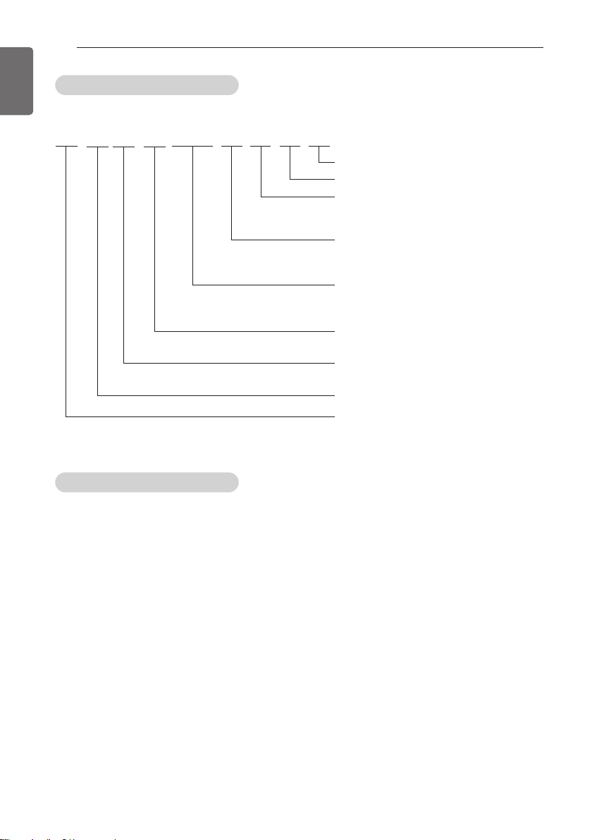
Model naming convention
ACHH020 LB AB
Development number
Communication method : A = Modbus
Model type : A = Module model
Power
specification :
Cooling capacity (RT) : 060 = 60 RT
Compressor type :
H = Scroll(High pressure type)
Cooled type : A = Air cooled C/O
Product type : C = Chiller
Area of production Refrigerant :
A = South Korea R410A
B = Independent model
C = Slave model
L = 380~415 V/50,60 Hz/3 Ø
H = 460 V/60 Hz/3 Ø
040 = 40 RT
020 = 20 RT
H = Air cooled H/P
Airborne Noise Emission
The A-weighted sound power of this product is 93 dB.
** The noise level can vary depending on the site.
The figures quoted are emission level and are not necessarily safe working levels. Whilst there is
a correlation between the emission and exposure levels, this cannot be used reliably to determine whether or not further precautions are required. Factor that influence the actual level of
exposure of the workforce include the characteristics of the work room and the other sources of
noise, i.e. the number of equipment and other adjacent processes and the length of time for
which an operator exposed to the noise. Also, the permissible exposure level can vary from country to country. This information, however, will enable the user of the equipment to make a better
evaluation of the hazard and risk.
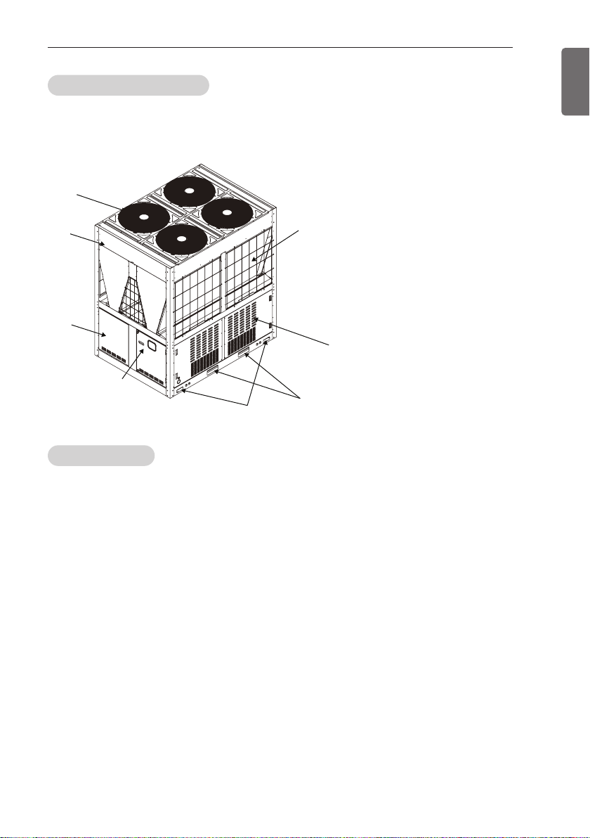
Product configuration
This chiller model is configured as shown below.
1
PRODUCT INTRODUCTION
13
ENGLISH
5
4
3
6
2
8
7
Legend
1. Fan motor
2. Fin & tube heat exchanger
3. Main Controller box
4. Sub Controller box
5. Condenser cover
6. Rope support
7. Forklift groove
8. Side cover
Cooling cycle
ACHH Series uses the high pressure type scroll compressor, and the suction gas part is separated from the high pressure discharge part and the motor is installed on the low pressure gas part.
Space for motor and storage for refrigerant is secured in the low pressure gas part to increase
the reliability for the liquid compression.
Because the sucked refrigerant gas cools the motor and flows to the compressor, separate cooling device to cool the compressor is not required. Inside the system, oil to lubricate the compressor is mixed with the refrigerant to discharge both the oil and refrigerant during the operation.
Because the oil discharged from the compressor can reduce the heat transfer efficiency when
thick layer is built up on the inner walls of the condenser and evaporator, device to prevent the
refrigerant and oil to be discharged together is added to prevent this issue.
This lubrication system ensures longer life for the compressor, improves the sealing of the compression space and provides low noise operation.
As the air cooled fin and tube type heat exchanger, the condenser is composed of heat exchanger in V shape, and the electronic expansion valve is used for efficient control in all load conditions.
The controller used in the chiller is exclusively for LG and monitors various sensors installed on
the product to protect the product.
For continuous supply of cold and hot water, the product is equipped with maximum continuous
operational function and also provides precision control to supply accurate target amount of cold
and hot water.
But the protective devices will immediately stop the product when the product reaches abnormal
condition or area limit.
In case of an issue, the controller of the chiller will provide helpful diagnostic message to the
administrator.
PRODUCT INTRODUCTION
14
ENGLISH
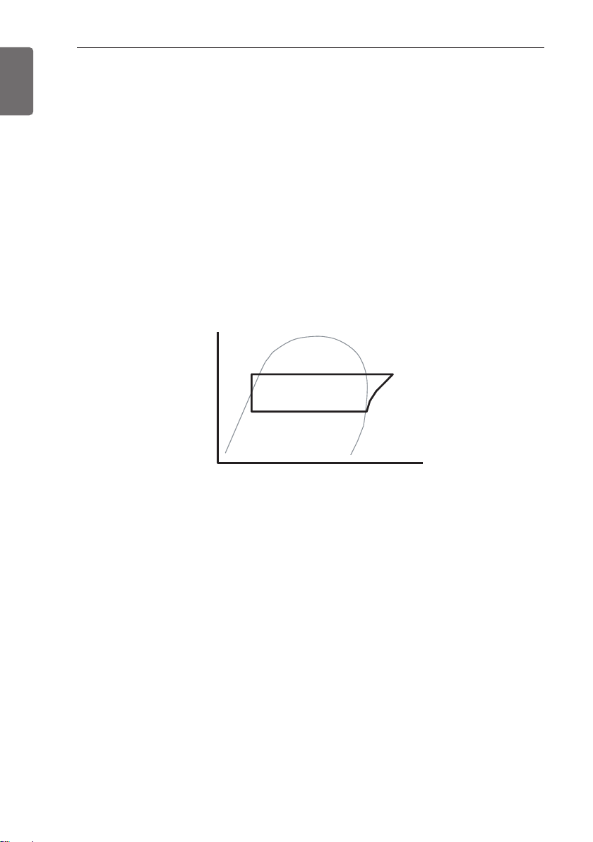
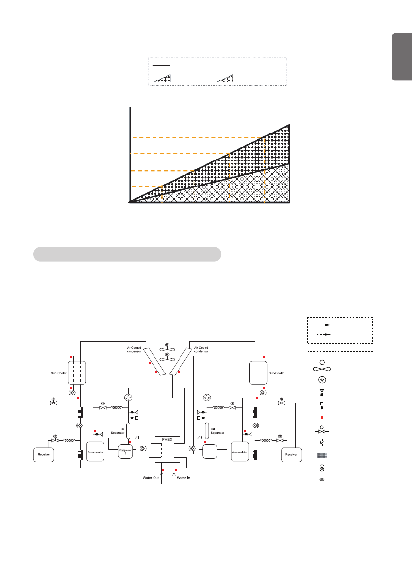
Description of cooling cycle
The cooling cycle of ACHH Series can be described using the following Pressure – Enthalpy
chart.
①,②,③,④ and ⑤ in the following chart shows the conditions of the refrigerant. The refrigerant
comes into the compressor motor and cools the motor, and becomes overheated and moves to
the suction inlet of the compressor. The oil inside the compressor seals the gap between the
compressor scrolls and provides lubrication for the bearing to help the compression of the refrigerant. During this time, the refrigerant is compressed and is discharged to the air cooled condenser. (②) The compressed refrigerant passes through the air cooled condenser and exchanges
the heat with the outdoor air. The condensed refrigerant then passes the condenser to be overcooled. (② → ③ → ④). The refrigerant that passed through the condenser expands in the electronic expansion valve to flow to the evaporator. (④ → ⑤). The refrigerant is evaporated in the
plate type heat exchanger, the evaporator. (⑤ → ①) Liquid refrigerant of low temperature pressure passes through the evaporator to cool the water flowing into the evaporator and the refrigerant itself receives the heat to evaporate to gas condition. (①) The refrigerant continues to change
the phase and continuously repeats the cooling cycle. For heating, the refrigerant flows in the
reverse direction to provide hot water.
Pressure
ں
ڻ
ڹ
ڼ
ڸ
Enthalpy
Lubrication system
Oil is efficiently separated inside the scroll compressor and even when the cycle operates, most
of the oil remains inside the scroll compressor. Only part of the oil will be mixed with the refrigerant to be circulated within the cycle.
Partial load operation
Each cooling cycle operates independently and 1 cooling cycle is composed of 2 inverter com-
pressor as shown below.
2 Inverter compressors increase the RPM after staring to operate to gradually increase the cool-
ing capacity.
The user can operate the product smoothly at optimal condition by setting the cooling capacity
based on the linear control of LG Chiller Controller and the product has efficient partial load performance at any load.
Load (%)
Cooling capacity
Capacity (%)
Inverter
compressor 1
Capacity (%)
100 %
75 %
50 %
25 %
0 %
25 % 50 % 75 % 100 %
Cooling capacityStatic speed compressor 1
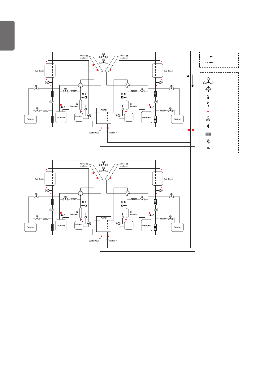
Cycle configuration and sensor location
This chiller model is configured as shown below.
1 UNIT
PRODUCT INTRODUCTION
Inverter
compressor 2
Load (%)
15
ENGLISH
Compressor
2
Cooling
Heating
M
Fan motor
4 way valve
Pressure sensor
Pressure switch
Temperature sensor
S
Solenoid valve
Check valve
Strainer
Electonic expantion
Valve
Expansion valve
ENGLISH
M
S
Cooling
Heating
Fan motor
4 way valve
Pressure sensor
Pressure switch
Solenoid valve
Check valve
Strainer
Electonic expantion
Valve
Expansion valve
Temperature sensor
Compressor
2
Compressor
2
PRODUCT INTRODUCTION
16
2 UNIT
Compressor
2
Compressor
2
Compressor
2
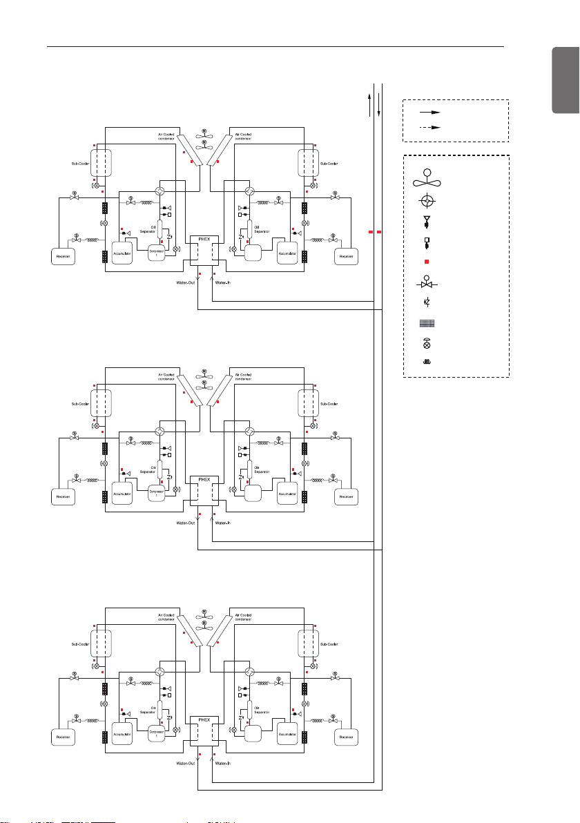
3 UNIT
PRODUCT INTRODUCTION
Cooling
Heating
M
Fan motor
4 way valve
Pressure sensor
Pressure switch
Temperature sensor
S
Solenoid valve
Check valve
Strainer
Electonic expantion
Valve
Expansion valve
17
ENGLISH
ENGLISH
PRODUCT INTRODUCTION
18
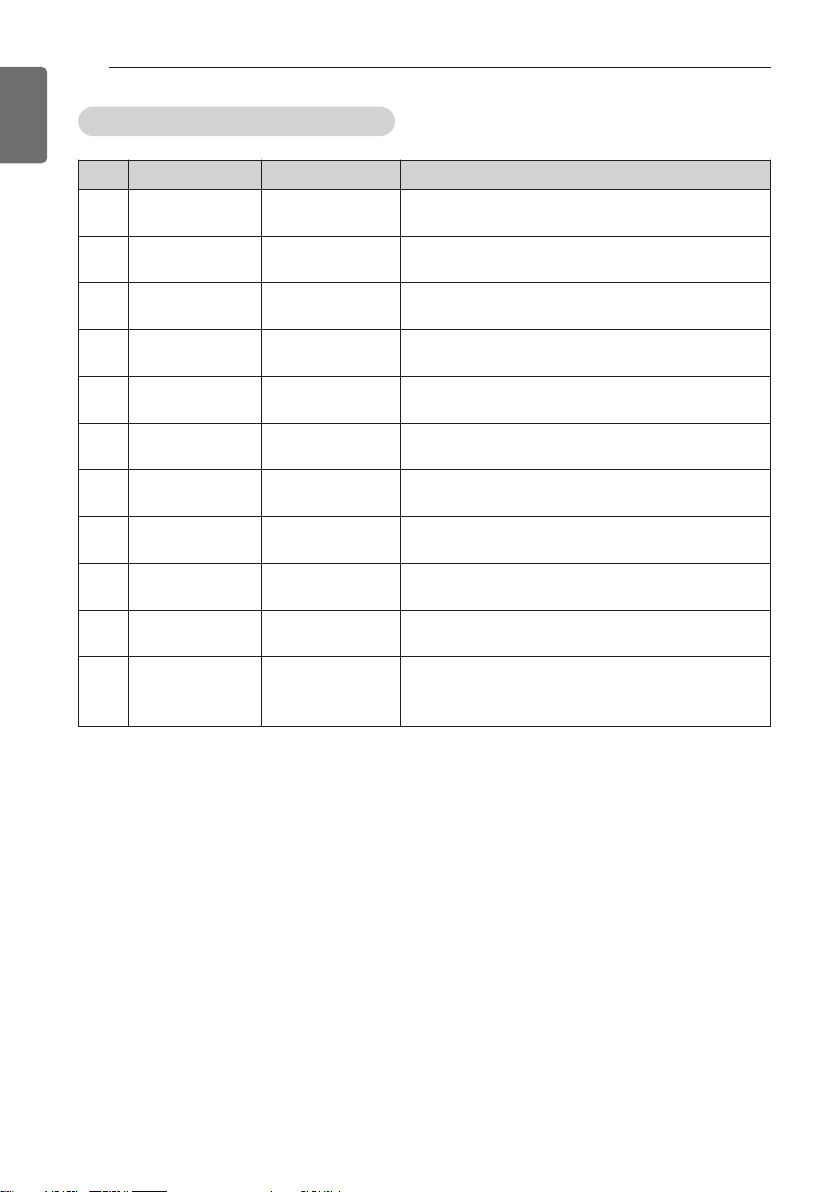
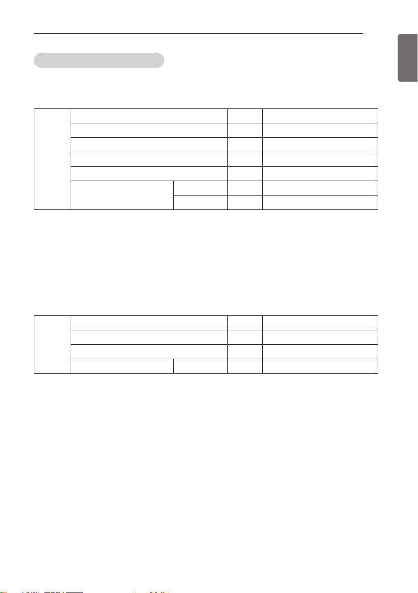
List of safety device and setting
No. Safety device Setting Function
High pressure
1
switch
2 Fuse
Compressor cir-
3
cuit breaker
Fan motor circuit
4
breaker
Discharge tem-
5
perature sensor
High pressure
6
sensor
Low pressure
7
sensor
Water pipe tem-
8
perature sensor
Reverse phase
9
detector
Liquid compres-
10
sor prevention
Compressor ratio
11
limit
3.8 MPa
250 V 5 A (Main)
250 V 15 A (INV)
35 A Measures and stops over-current per compressor
7 A Measures and stops over-current per motor
110 °C Stops compressor in stages
3 801 KPa
0.22 MPa
Off : 3 °C Prevent evaporator from freezing
-
-
9
Stops operation of the module when the pressure
is above the setting
Disconnects current when it exceeds the normal
value
Starts protective operation control to reduce the
cycle pressure
Starts protective operation control to raise the
cycle pressure
Compares the current of each phase and stops
when it is in reverse phase
Discharge over-heating level goes up to prevent
liquid compression
Compressor frequency is reduced when operating
at high compression ratio to prevent the internal
parts within the compressor from being damaged
PRODUCT INTRODUCTION
Operation range and limit
The following table shows the operation range of the product. Do not operate the product
exceeding the following operation range.
H/P
Voltage V 342~457
Cold water inlet temperature °C 8 or above
Operation
range
(1) Product performance range at rated condition is 20-100 %.
- Cooling rate condition: Outdoor temperature 35 °C, Water inlet temp. 12 °C. Water Outlet
temp. 7 °C
- Heating rate condition: Outdoor temperature 7 °C, Water inlet temp. 40 °C. Water Outlet
temp. 45 °C
(2) When running heating operating with outdoor temperature is less than 7 °C, Inlet water tem-
perature must be at least 20 °C.
C/O
Operation
range
(1) Product performance range at rated condition is 20-100 %.
- Cooling rate condition: Outdoor temperature 35 °C, Water inlet temp. 12 °C. Water Outlet
temp. 7 °C
Cold water outlet temperature °C 4 ~ 20
Heat water inlet temperature °C 25 ~ 52
Heat water outlet temperature °C 30 ~ 55
Outdoor temperature
Voltage V 342~457
Cold water inlet temperature °C 8 or above
Cold water outlet temperature °C 4 ~ 20
Outdoor temperature Cooling °C -15 ~ 48
Cooling °C -15 ~ 48
Heating °C -30 ~ 35
19
ENGLISH
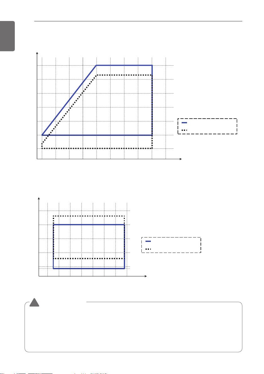
PRODUCT INTRODUCTION
Outdoor temperature
Water temperature
Outlet water temperature
Inlet water temperature
-20 °C -10 °C 0 °C 10 °C 20 °C 30 °C 40 °C 50 °C
10 °C
15 °C
20 °C
25 °C
5 °C
4 °C
48 °C
8 °C
-15°C-20°C-25°C-30°C -5°C 5°C 15°C 25°C 35°C 45°C Outdoor temperature
40°C
45°C
50°C
55°C
35°C
25°C
30°C
Water temperature
42°C
52°C
26°C
Outlet water temperature
Inlet water temperature
20
ENGLISH
Operation range of heating mode
Operation range of cooling mode
CAUTION
!
When running cooling operation with outdoor temperature is less than -10 °C, depending on
inlet temperature, the product does not operate normally, or can take a long time for running.
In this case, Please running operation After raising the inlet temperature by circulating load
water.
Please add antifreeze when operating at ambient temperature less than 5 °C. (There is a risk
of freeze.)
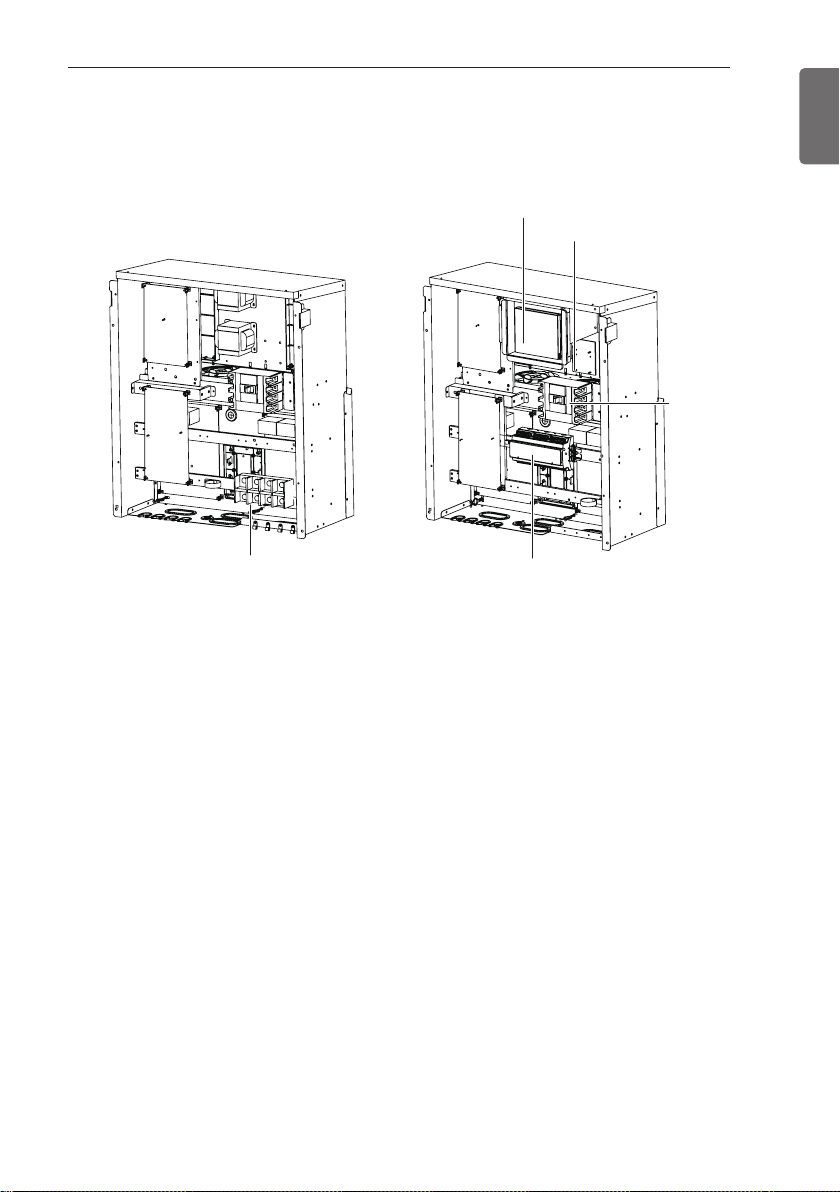
CONTROL
Control panel configuration
HMI
Power supply
CONTROL
MCCB
21
ENGLISH
Terminal block
Sub Control Box Main Control Box
<Inside control panel>
• HMI (Human Machine Interface)
This is for basic product setting and command, and shows the information of product and each
cycle.
• Main controller
This controls the input/output port and the communication with each cycle.
• Power supply
This supplies the power to the HMI.
• MCCB (Molded Case Circuit Breaker)
This shuts off the overcurrent.
• Terminal block
This is the terminal block that receives the main power externally.
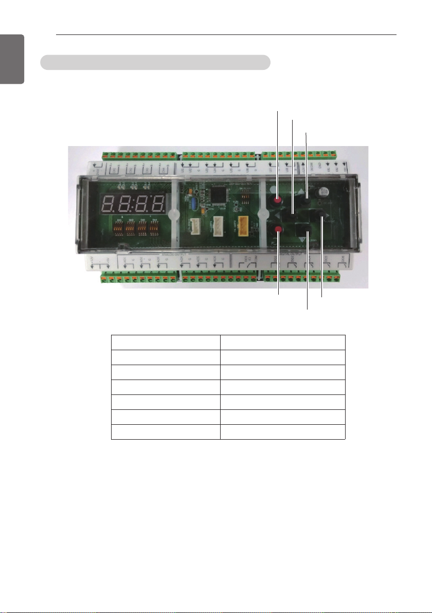
Main controller
ENGLISH
CONTROL
22
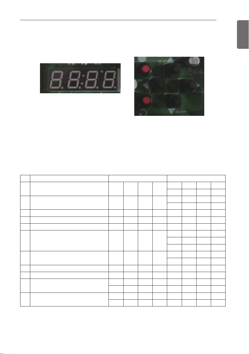
Chiller controller rotary, DIP switch setting
Switch location
SW_COMF
SW_LEFT
SW_UP
SW_BACK
Name Description
SW_RIGHT Changes the setting.
SW_UP Moves the screen.
SW_LEFT Changes the setting.
SW_DOWN Moves the screen.
SW_COMF Sets the selected function.
SW_BACK Moves to the previous step.
Chiller Controller includes the buttons described above so that the following functions are available for setting without HMI.
SW_RIGHT
SW_DOWN
CONTROL
Option Setting
Press SW_COMF Button to move to O Level Setting Screen.
<Screen>
<Button>
Press Up or Down (▲▼) Button to go to a desired function.
If the desired function shows, press SW_COMF Button.
Then, the Screen moves to 1 Level Setting.
Press Left or Right (◀▶) Buttons to go to a desired function. And Press SW_COMF Button to
set the function.
To go to the previous, press SW_BACK Button.
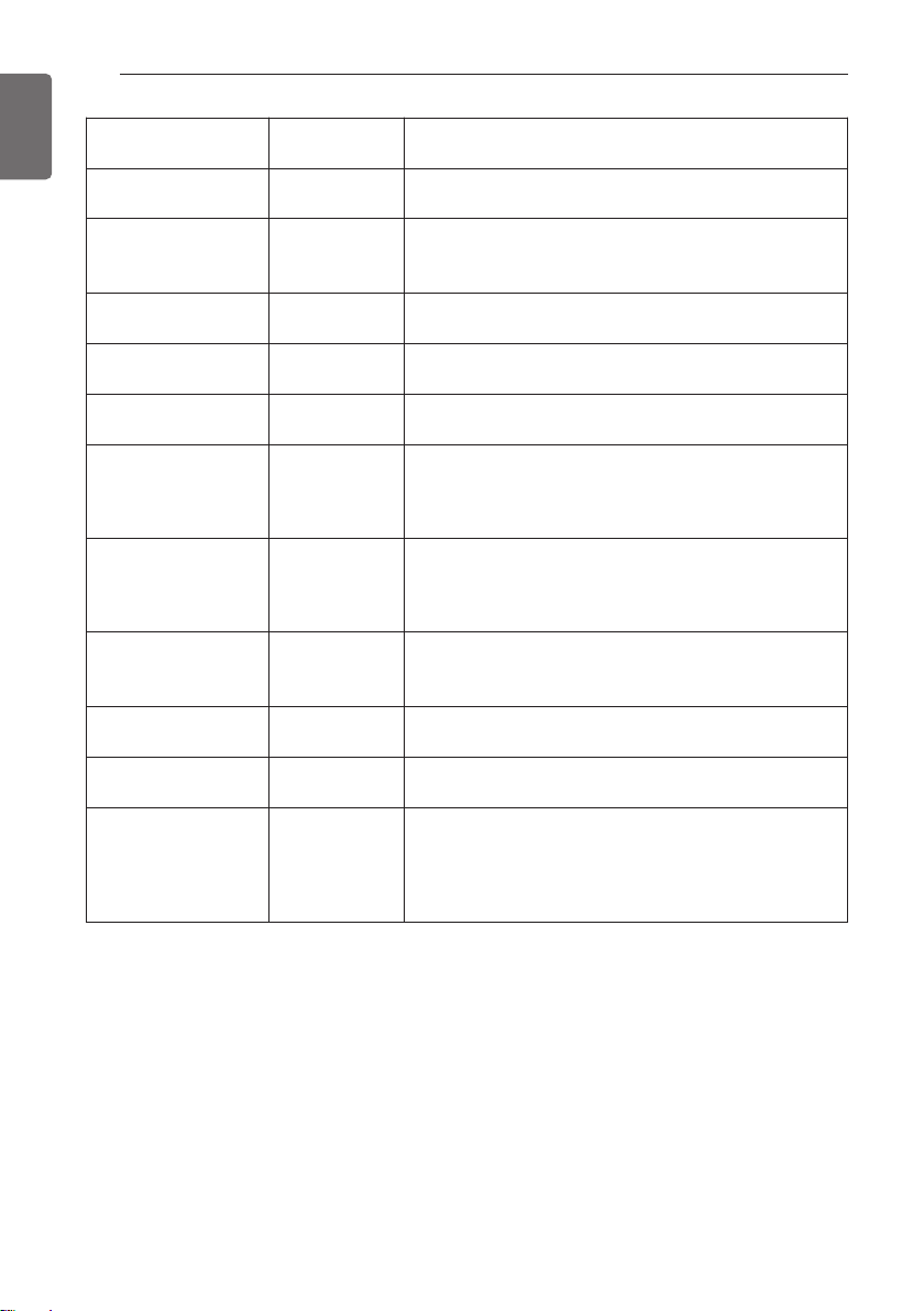
Description Screen Displays(0 Level) Screen Displays(1 Level)
1 Start/Stop O P E R
2 Cooling/Heating C Y C L
3 Cooling setpoint temperature C - T E 7
4 Heating setpoint temperature H - T E 4 5
5 Load outflow Temperature
6 Control Mode S Y S 1
7 Remote Mode S Y S 2
8 Central Control Address A D D R 1
9 Maximum Operation Frequency H I - R 1 1 0
10 Capacity of product
11 Version
HP4 0
CO4 0
10
SV10
RUN
STOP
HEAT
COOL
LOC
DIST
SCHE
CONT
BUS
23
ENGLISH
ENGLISH
CONTROL
24
Description
Start/Stop RUN /STOP
Cooling/Heating HEAT/COOL
Cooling setpoint tem-
perature
Heating setpoint tem-
perature
Load outflow water
Temperature
Control Mode LOC/DIST/SCHE
Remote Mode CONT/BUS
Central Control
Address
Maximum Operation
Frequency
Capacity of product -
Version -
Screen Display
(1 Level)
110
Detail Description
Set RUN to operate the product and STOP to stop the
operation.
Sets the product’s Cooling/Heating Operation Mode.
COOL selects Cooling Mode and HEAT selects Heating Mode.
7 Sets Cooling Target Temperature. (4 °C~ 20 °C)
45 Sets Heating Target Temperature.(30 °C~ 55 °C)
-
1
Shows the temperature value of Load outflow water.
(Specified in 0 Level)
Set’s the product’s Control Mode. In LOC, the product
control is available with HMI and Chiller Controller.
DIST refers Remote Control Mode. In SCHE, the product is controlled following the schedule set at HMI.
Sets how to set in Remote Mode. CONT enables the
product’s operation mode by simple switch contacts.
BUS enables the control on the entire product through
communication from other communication devices.
The product address can be set for communication
with other communication devices. The address can
be set by selecting values from 1-247.
Sets the Maximum Operation Frequency.(70 Hz~130
Hz)
Shows the current Capacity of product.
(Specifies in 0 Level)
Shows the program information of Chiller Controller
installed in the current product as Version. Version
information is subjected to change for improvement of
the product performance or the quality improvement.
(Specifies in 0 Level)
CONTROL
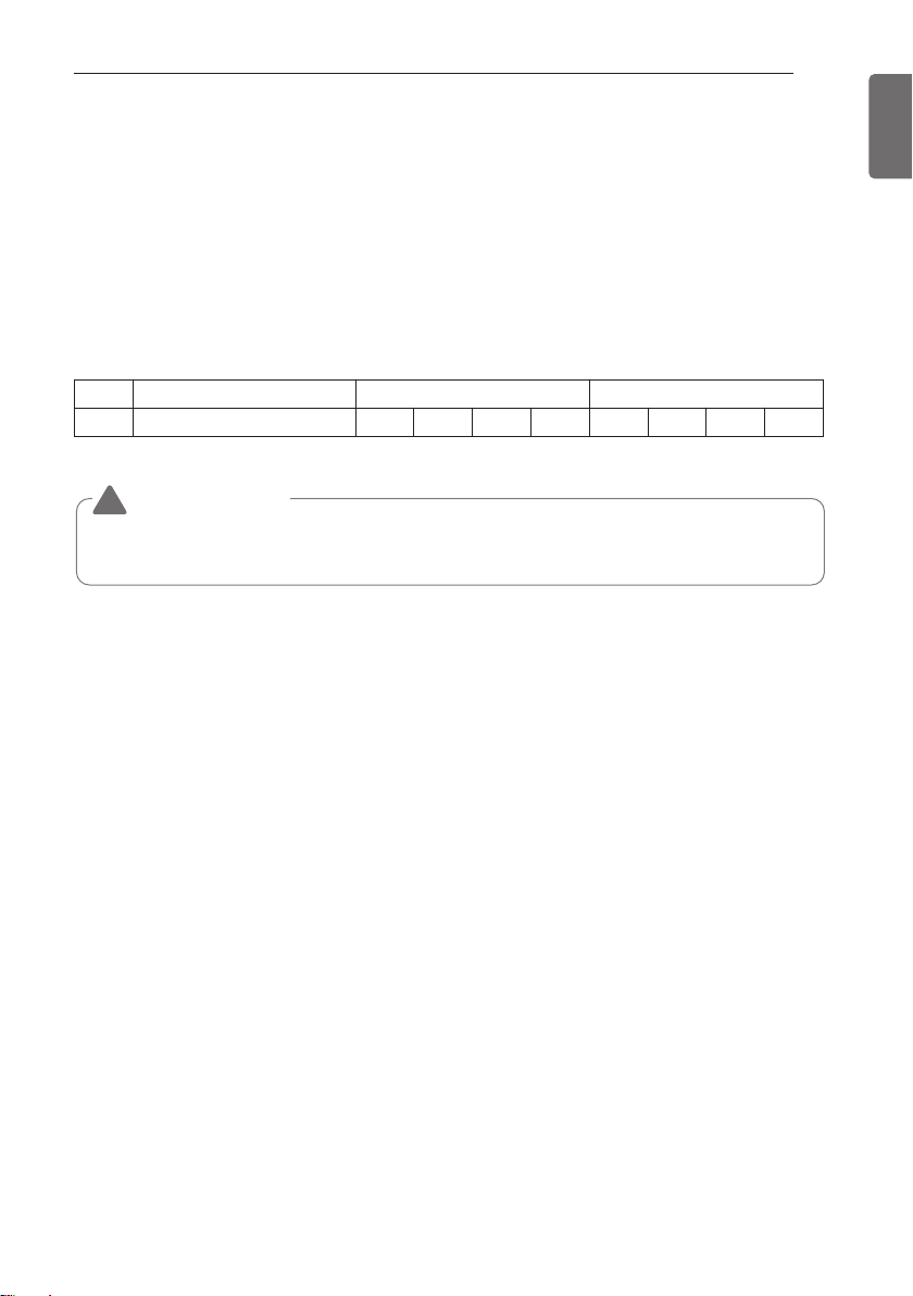
Freezer address setting
Address setting of product should be set from HMI and Main Controller and if 2 addresses doesn’t match each other, HMI communication error will occur.
• Main Controller address setting
Press down direction and right direction button (▼▶) at the same time.
When FN01 appears, press SW_CONF button.
Select desired address using left and right button (◀▶) and address will be set if press
SW_CONF button. If you don’t want, please press SW_CONF button.
Description Screen Displays(0 Lever) Screen Displays(1 Lever)
1 Chiller Address F N 0 2 1
CAUTION
!
• If Main Controller address doesn’t match HMI address, Error will occur. (please refer to control>freezer interlocking control about HMI address setting)
25
ENGLISH
CONTROL
26
ENGLISH
Logging in to HMI
This chapter will explain about the composition of each screen in HMI, detail functions, and operation methods. When power is applied to HMI, HMI automatically operates. When HMI starts,
Home screen appears.
CAUTION
!
When HMI is installed indoors, the guaranteed communication distance is 500 m.
- Guaranteed communication distance of HMI: 500 m
(But, when connected indoor, the end resistance (100-200 Ω) must be installed at the terminal connected to HMI for smooth communication. In this case, if the installation location of
the Unit is different from that of HMI, the maximum permitted connection distance of the
communication cable between the two locations is displayed.)
CONTROL
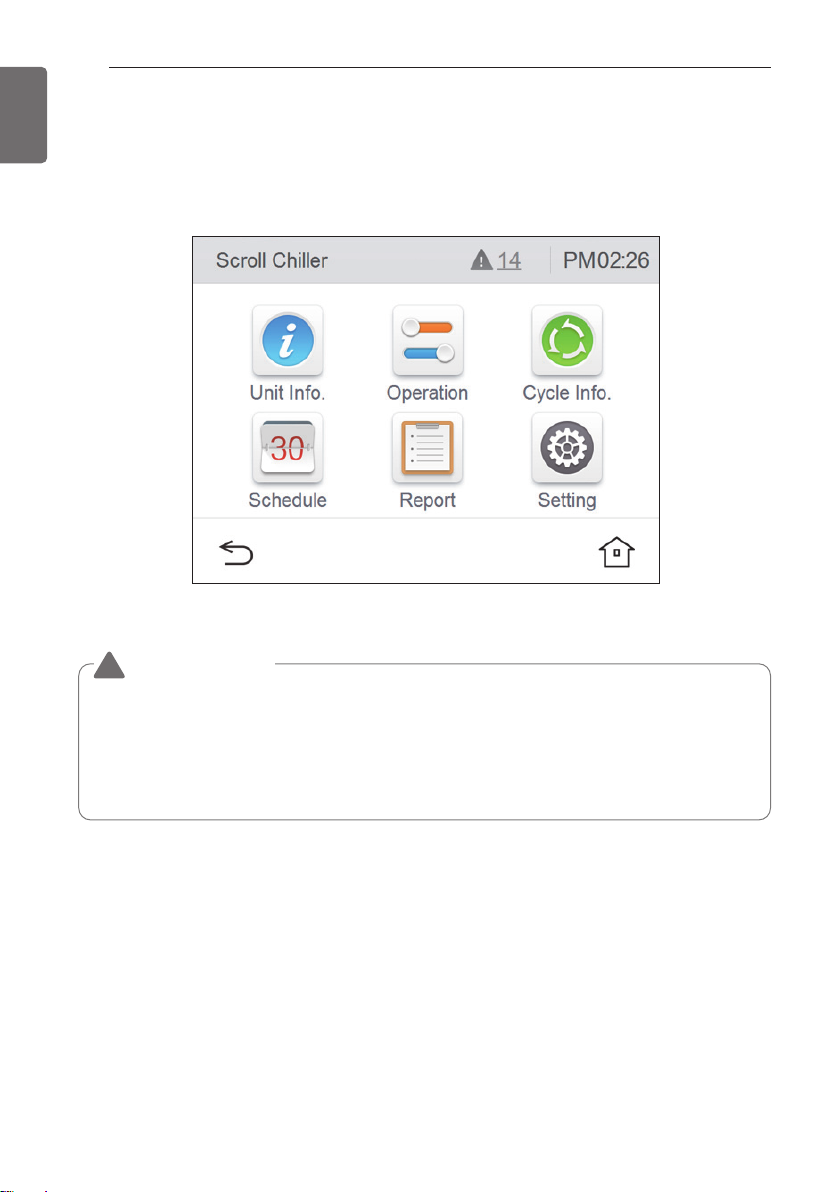
Introduction to HMI menu
This chapter describes the HMI menus to know to operate the product and how the screen is
configured.
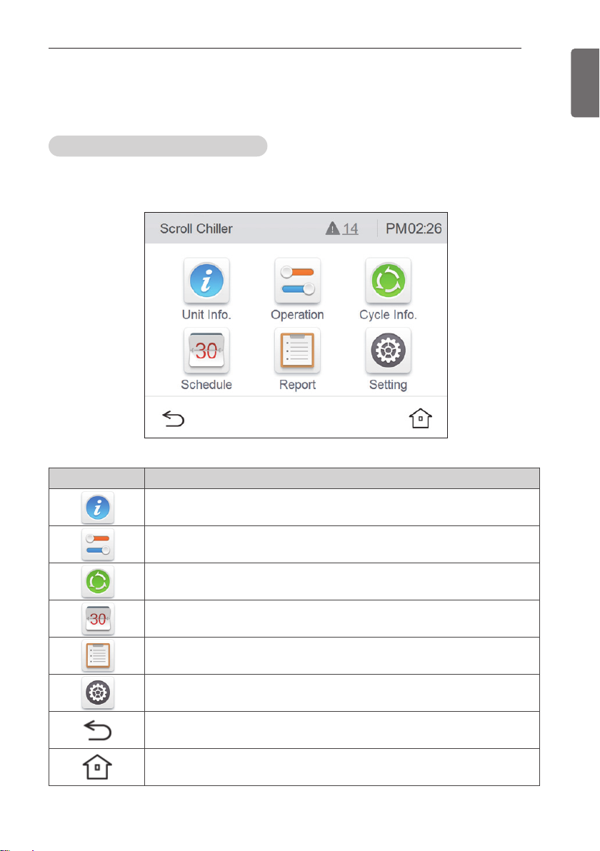
HMI main screen configuration
After logging in to HMI, the system view screen that shows the common information of the
product is displayed as shown below.
27
ENGLISH
Icon Description
You can see the load water temperature, pump/flow amount status, and system information.
It sets the Start/Stop, Set Temperature, Operation Mode (Only for Heatpump
Model), control mode, max. operation frequency, and demand control ratio are set.
It checks the individual cycle’s operation information.
It checks the set schedule.
It checks the occurred error history.
It sets the installer setting, screen setting, and system setting.
It returns to the previous menu.
Home screen appears.
CONTROL
28
ENGLISH
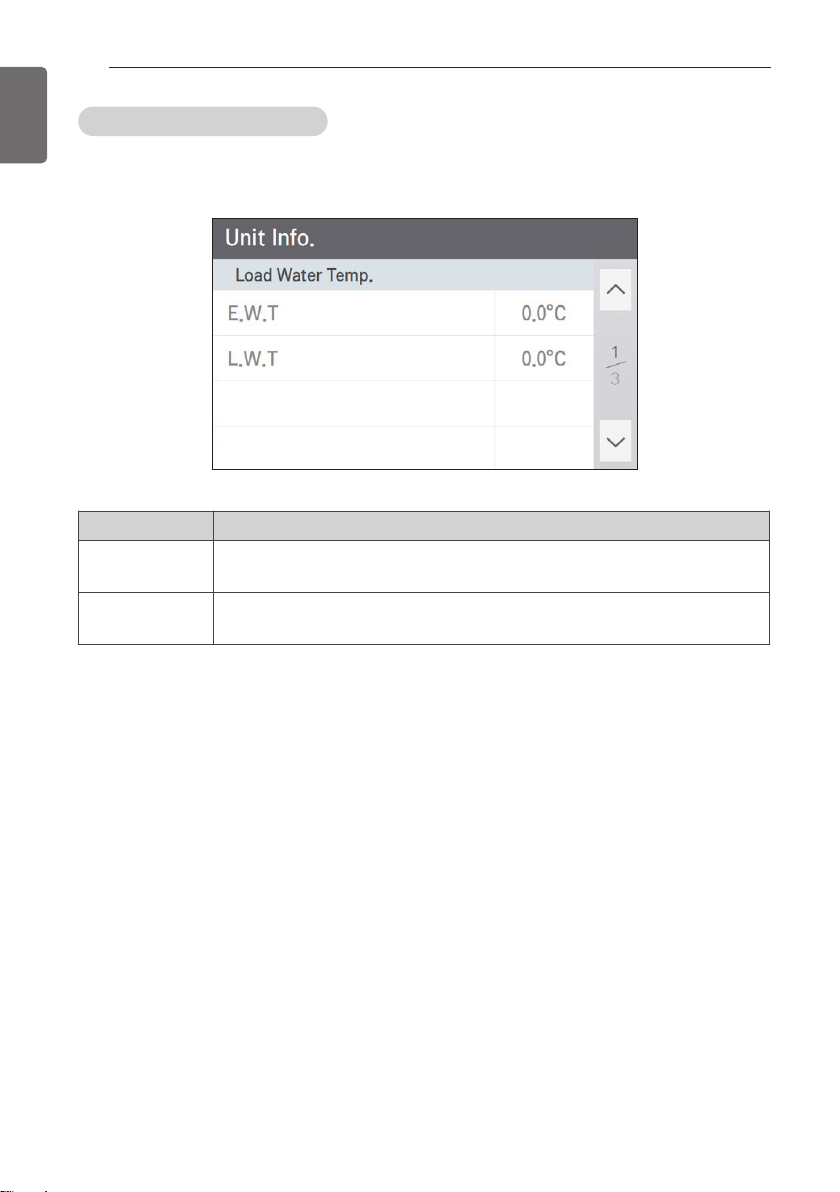
View chiller information
Chiller information is composed of the load water temperature, pump/flow amount status, and
system information.
• Load water temperature screen
Icon Description
E.W.T It shows the common load entering water temperature value.
L.W.T It shows the common load leaving water temperature value.
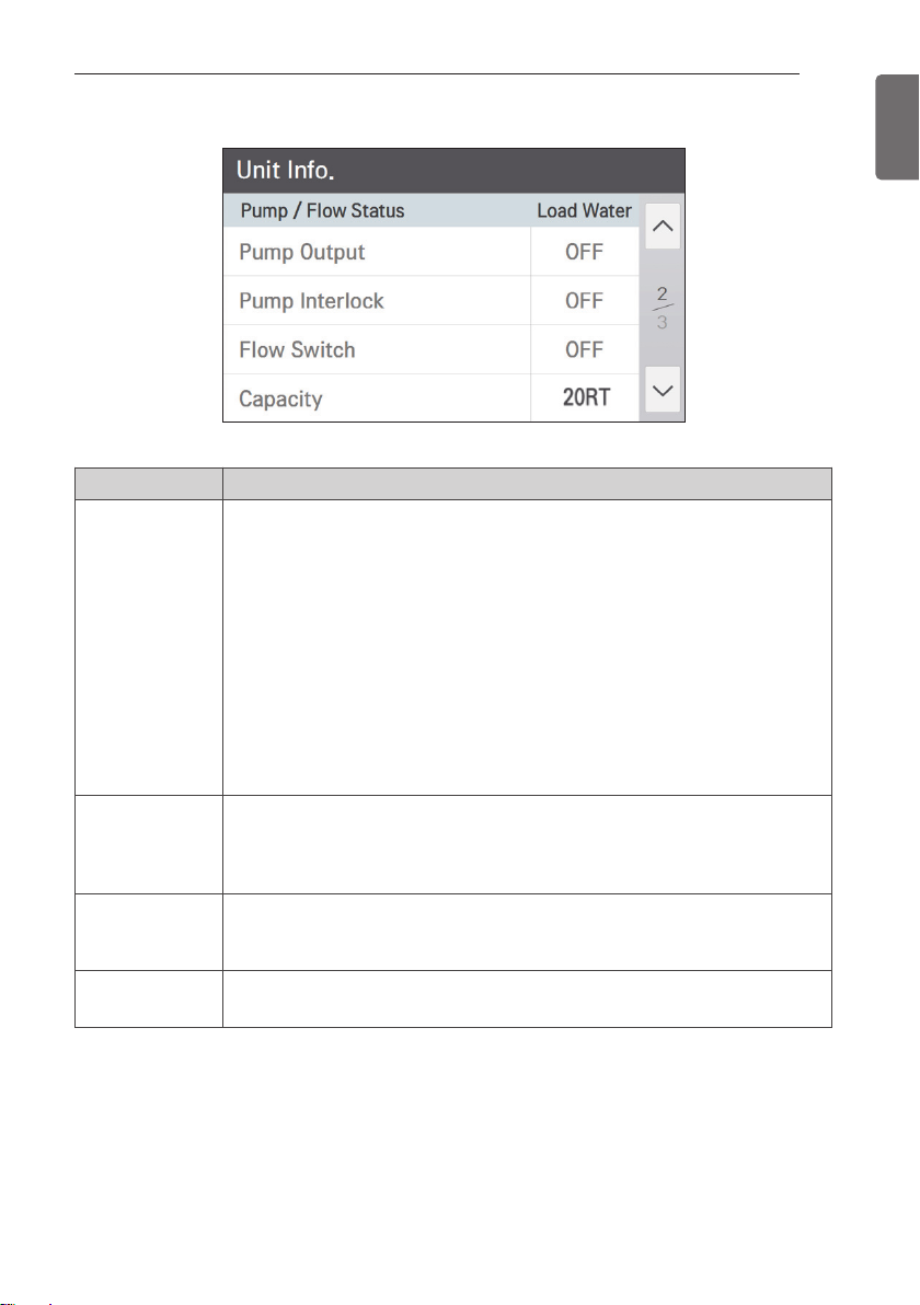
• Pump/flow amount status screen
Icon Description
If it is in operation, it always maintains ON, and when the product operation is
stopped, the freeze and burst mode is applied, and the freeze and burst prevention
mode operates as follows.
According to the outdoor air temperature condition, the load water pump repeats
operation ON and OFF.
Pump Output
Outdoor air temperature < 1 °C → always “ON”
1 °C ≤ outdoor air temperature < 5 °C → 2 min. operation and 18 min. stop
Outdoor air temperature ≥ 5 °C → operation “OFF”
The freeze and burst prevention mode is possible when the pump is connected, and
to interface with the pump, Pump Output connect shall be connected, and to check
whether the pump operates, Pump Interlock connector shall be connected.
(For the connector connection method, refer to the connection diagram.)
CONTROL
29
ENGLISH
It receives the status of the load water pump output through the external signal con-
Pump Interlock
Flow Switch
Capacity It shows the capacity of the device.
tact point of the pump.
(When the product is in operation, the pump output shall maintain “ON” state, and
otherwise, alarm will occur.)
It shows the current load water’s flow amount switch status value.
(When the product is in operation, the pump output shall maintain “ON” state, and
otherwise, alarm will occur.)
CONTROL
30
ENGLISH
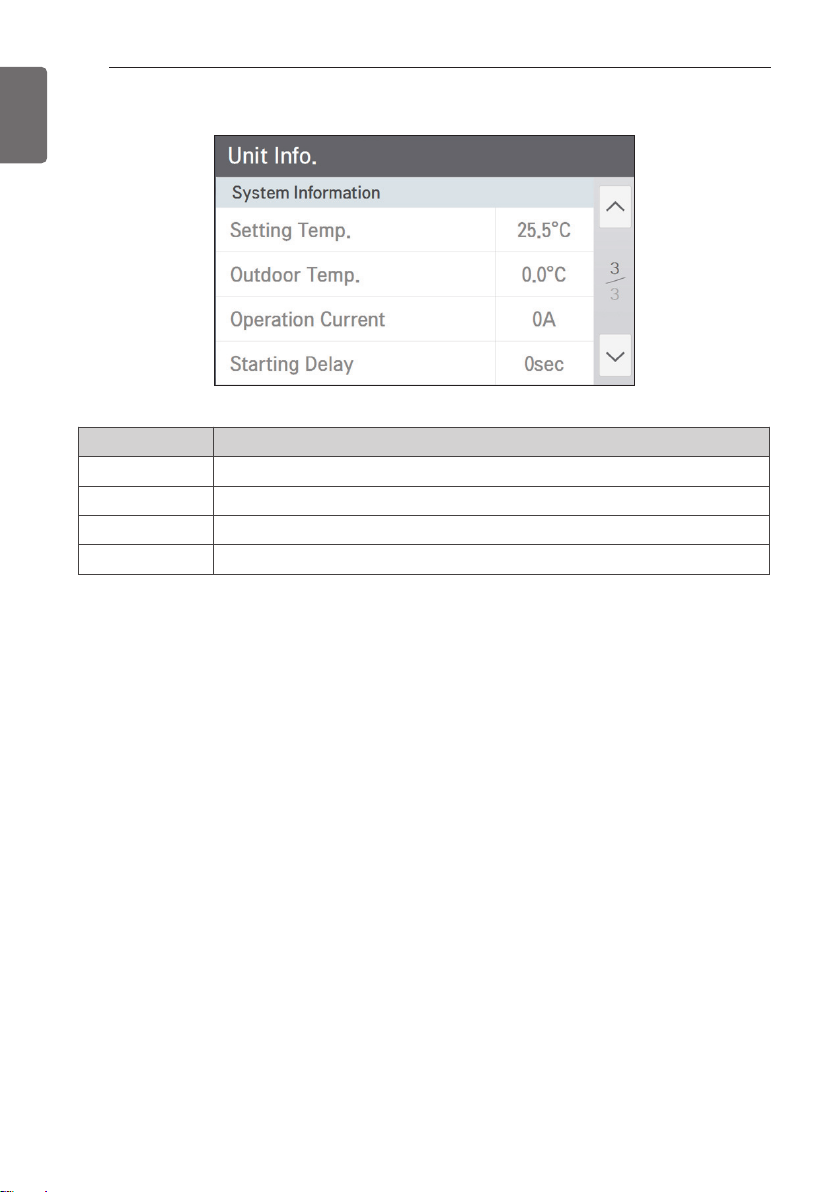
• System information screen
Icon Description
Setting Temp. It shows the set temperature for the current operation mode.
Outdoor Temp. It shows the current outdoor air temperature value.
Operation Current It shows the operation compressor’s overall operation current value.
Starting Delay It shows the time of the standby state before starting the product.
 Loading...